EP0895615B1 - Verfahren und vorrichtung zum schleifen von konzentrisch zylindrischen bereichen von werkstücken - Google Patents
Verfahren und vorrichtung zum schleifen von konzentrisch zylindrischen bereichen von werkstücken Download PDFInfo
- Publication number
- EP0895615B1 EP0895615B1 EP97919519A EP97919519A EP0895615B1 EP 0895615 B1 EP0895615 B1 EP 0895615B1 EP 97919519 A EP97919519 A EP 97919519A EP 97919519 A EP97919519 A EP 97919519A EP 0895615 B1 EP0895615 B1 EP 0895615B1
- Authority
- EP
- European Patent Office
- Prior art keywords
- workpiece
- grinding
- wheelfeed
- region
- eccentricity
- Prior art date
- Legal status (The legal status is an assumption and is not a legal conclusion. Google has not performed a legal analysis and makes no representation as to the accuracy of the status listed.)
- Expired - Lifetime
Links
Images


Classifications
-
- G—PHYSICS
- G05—CONTROLLING; REGULATING
- G05B—CONTROL OR REGULATING SYSTEMS IN GENERAL; FUNCTIONAL ELEMENTS OF SUCH SYSTEMS; MONITORING OR TESTING ARRANGEMENTS FOR SUCH SYSTEMS OR ELEMENTS
- G05B19/00—Program-control systems
- G05B19/02—Program-control systems electric
- G05B19/18—Numerical control [NC], i.e. automatically operating machines, in particular machine tools, e.g. in a manufacturing environment, so as to execute positioning, movement or co-ordinated operations by means of program data in numerical form
- G05B19/416—Numerical control [NC], i.e. automatically operating machines, in particular machine tools, e.g. in a manufacturing environment, so as to execute positioning, movement or co-ordinated operations by means of program data in numerical form characterised by control of velocity, acceleration or deceleration
- G05B19/4166—Controlling feed or in-feed
-
- G—PHYSICS
- G05—CONTROLLING; REGULATING
- G05B—CONTROL OR REGULATING SYSTEMS IN GENERAL; FUNCTIONAL ELEMENTS OF SUCH SYSTEMS; MONITORING OR TESTING ARRANGEMENTS FOR SUCH SYSTEMS OR ELEMENTS
- G05B2219/00—Program-control systems
- G05B2219/30—Nc systems
- G05B2219/33—Director till display
- G05B2219/33078—Error table, interpolate between two stored values to correct error
-
- G—PHYSICS
- G05—CONTROLLING; REGULATING
- G05B—CONTROL OR REGULATING SYSTEMS IN GENERAL; FUNCTIONAL ELEMENTS OF SUCH SYSTEMS; MONITORING OR TESTING ARRANGEMENTS FOR SUCH SYSTEMS OR ELEMENTS
- G05B2219/00—Program-control systems
- G05B2219/30—Nc systems
- G05B2219/37—Measurements
- G05B2219/37308—Measure workpiece relieved from stress, redrawn, disengaged tool
-
- G—PHYSICS
- G05—CONTROLLING; REGULATING
- G05B—CONTROL OR REGULATING SYSTEMS IN GENERAL; FUNCTIONAL ELEMENTS OF SUCH SYSTEMS; MONITORING OR TESTING ARRANGEMENTS FOR SUCH SYSTEMS OR ELEMENTS
- G05B2219/00—Program-control systems
- G05B2219/30—Nc systems
- G05B2219/37—Measurements
- G05B2219/37339—Eccentricity, cylindricity, circularity
-
- G—PHYSICS
- G05—CONTROLLING; REGULATING
- G05B—CONTROL OR REGULATING SYSTEMS IN GENERAL; FUNCTIONAL ELEMENTS OF SUCH SYSTEMS; MONITORING OR TESTING ARRANGEMENTS FOR SUCH SYSTEMS OR ELEMENTS
- G05B2219/00—Program-control systems
- G05B2219/30—Nc systems
- G05B2219/37—Measurements
- G05B2219/37576—Post-process, measure worpiece after machining, use results for new or same
-
- G—PHYSICS
- G05—CONTROLLING; REGULATING
- G05B—CONTROL OR REGULATING SYSTEMS IN GENERAL; FUNCTIONAL ELEMENTS OF SUCH SYSTEMS; MONITORING OR TESTING ARRANGEMENTS FOR SUCH SYSTEMS OR ELEMENTS
- G05B2219/00—Program-control systems
- G05B2219/30—Nc systems
- G05B2219/41—Servomotor, servo controller till figures
- G05B2219/41427—Feedforward of position
-
- G—PHYSICS
- G05—CONTROLLING; REGULATING
- G05B—CONTROL OR REGULATING SYSTEMS IN GENERAL; FUNCTIONAL ELEMENTS OF SUCH SYSTEMS; MONITORING OR TESTING ARRANGEMENTS FOR SUCH SYSTEMS OR ELEMENTS
- G05B2219/00—Program-control systems
- G05B2219/30—Nc systems
- G05B2219/49—Nc machine tool, till multiple
- G05B2219/49184—Compensation for bending of workpiece, flexible workpiece
-
- G—PHYSICS
- G05—CONTROLLING; REGULATING
- G05B—CONTROL OR REGULATING SYSTEMS IN GENERAL; FUNCTIONAL ELEMENTS OF SUCH SYSTEMS; MONITORING OR TESTING ARRANGEMENTS FOR SUCH SYSTEMS OR ELEMENTS
- G05B2219/00—Program-control systems
- G05B2219/30—Nc systems
- G05B2219/50—Machine tool, machine tool null till machine tool work handling
- G05B2219/50059—Record profile error, used for next machining pass
Definitions
- This invention concerns the grinding of cylindrical sections of workpieces which should be concentric in rotation, such as the journal bearing regions of a crankshaft.
- a workpiece is rotated about its primary axis and the or each cylindrical section of the crankshaft is ground in a conventional way by moving a grinding wheel into a grinding position so as to remove material from the workpiece and produce a cylindrical region thereon.
- EP-A1-0282776 there is disclosed a honing process in which honing stones on an arbor are pressed outwardly against an internal surface of a workpiece. While the stones are still lightly pressing against the surface, after preliminary honing, a measurement procedure is carried out which is processed by a computer, and the latter then causes the normal reciprocating honing stroke to be altered.
- Such a known process is not suitable for compensating for unwanted eccentricity introduced in an externally ground cylindrical region.
- the speed at which a honing stone operates against a workpiece is of a whole order of magnitude lower than that of a present-day external grinding machine.
- a method of setting up a computer controlled grinding machine having a grinding wheel for concentrically grinding an external cylindrical region of a workpiece comprises the steps of loading a programme containing data about the workpiece, loading a programme containing wheelfeed instructions, running the wheelfeed programme instructions so as to grind the workpiece region, disengaging the grinding wheel, measuring any unwanted eccentricity introduced into the region by the grinding process together with the angular position thereof, and adjusting the wheelfeed programme instructions or control signals to form corrected wheelfeed programme instructions or control signals, so that during subsequent grinding of the said region, or of similar regions of similar workpieces, the wheelfeed is controlled to produce a complementary eccentricity so as to compensate for the measured unwanted eccentricity.
- the measuring of the workpiece region occurs after it has been stress relieved, which may be achieved merely by disengaging the grinding wheel, but may involve removing the workpiece from the grinding machine.
- the setting up process measurements may be performed on a concentric cylindrical region approximately midway along the said axial length of the workpiece, and proportionately reduced corrections are applied to the wheelfeed programme instructions or control signals for similar regions to be ground which are displaced from the mid position towards the supported ends of the workpiece.
- the method involves the steps of cylindrically grinding all of the cylindrical surfaces of a workpiece which are to be concentric with the primary workpiece axis without introducing any compensation for unwanted eccentricity introduced by the grinding process forces, thereafter making measurements on the workpiece to determine any unwanted eccentricity and the angular position thereof about the primary workpiece axis of rotation for each of the ground regions, and separately adjusting each of the wheelfeed programme instructions or control signals to be used to control the wheelfeed during the subsequent grinding of the or another such workpiece, at each of the corresponding said regions thereof, so as to compensate individually for any process-induced eccentricity in each said region.
- a further check on the reground workpiece may be made, and second order corrections may be made to the wheelfeed programme instructions or control signals, before grinding further workpieces.
- Measurements may be made subsequent to each further workpiece grinding to determine whether the corrections made from earlier measurements sufficiently compensate for any unwanted process induced eccentricity, and further corrections may be made to the wheelfeed programme instructions or control signals as required. The process may be repeated until the measurements made on a test workpiece indicate that the unwanted eccentricity of each ground region is within desired limits. Thereafter the grinding machine wheelfeed may be controlled to grind further workpieces in accordance with the finally modified set of wheelfeed programme instructions or control signals.
- each stage may be preferable at each stage to grind a number of workpieces which together form a sample, and to perform eccentricity measurements on the workpieces in each sample, and thereby determine the extent of any unwanted eccentricity both in terms of angular position and radial extent for each region of each workpiece in each sample, and to determine the mean unwanted eccentricity and mean angular position of such eccentricity for each sample, for use as the basis for the correction to the wheelfeed programme instructions or control signals.
- the invention also lies in a method of grinding concentric cylindrical regions of similar workpieces comprising the steps of setting up modified wheelfeed programme instructions or control signals in any of the aforesaid ways, and thereafter grinding cylindrical surfaces of workpieces similar to that used in the setting up process, using the modified wheelfeed programme instructions or control signals derived from the setting up procedure to control the wheelfeed drive during each grinding.
- the invention thus allows the known software controlled crankpin following facility incorporated into computer controlled grinding machines to permit a grinding wheel to follow the relatively large eccentric movement of a crankpin during grinding as the crankshaft rotates, to be utilised, albeit acting at a smaller scale, to compensate for said unwanted eccentricity introduced into cylindrically ground surfaces of a workpiece which should be concentric as a consequence of grinding process forces exerted as such surfaces are ground, which unwanted eccentricity tends to appear after the workpiece is stress relieved.
- the invention thus in effect provides for eccentrically grinding regions of workpieces which are to have concentric cylindrical surfaces relative to the workpiece primary axis rather than concentrically grinding such regions, the degree of eccentricity being such that when a ground workpiece is stress relieved after grinding, the regions in fact will be concentric relative to the primary axis of the workpiece.
- the invention is of particular application to the grinding of journal bearing regions on crankshafts, but it is to be understood that the invention is equally applicable to the grinding of any cylindrical concentric workpiece section so as to remove eccentricity which the grinding process can introduce into the workpiece, and which becomes evident as the latter becomes unstressed.
- the grinding process performed by the machine will reduce any unwanted eccentricity introduced by grinding process forces into what should be a concentric workpiece region, by grinding each such region so as to be complementarily eccentric to any eccentricity which would be introduced by the grinding process forces.
- complementary is meant equal in magnitude but opposite in sense (direction).
- the wheelfeed drive includes two modes, a first mode for normal advance and withdrawal, and a second mode in which very small but very precise adjustments can be made to the instantaneous wheel position so that during grinding, with the grinding wheel in contact with the workpiece and surface grinding being performed, the grinding wheel can be urged backwards and forwards by very small amounts in synchronism and appropriate phase with the rotation of the workpiece, using corrected wheelfeed programme instructions or control signals as aforesaid, so as to compensate for any eccentricity which would otherwise arise in the grinding of the workpiece region due to forces arising during the grinding process.
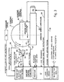
- Figure 1 shows a grinding machine 10 having a grinding wheel 12 driven by a motor 14 and mounted on a wheelhead 16 for movement towards and away from a workpiece 18 along a linear track 20 under the control of the wheelfeed drive motor 22.
- the workpiece 18 is mounted on a carriage 70 itself slidable on a slideway 32 and driven thereby to position the workpiece relative to the wheel, via a drive 74.
- the workpiece is mounted between centres in a tailstock 24 and a headstock 26 (themselves mounted on the carriage 70).
- the headstock houses a motor (not shown) for rotating the workpiece 18 via a chuck 28.
- the workpiece shown is a crankshaft of an internal combustion engine and includes offset crankpins 30 (which are eccentric to the main crankshaft axis), and cylindrical bearing regions 31, which are to be ground to size, each bearing region constituting a cylindrical workpiece region for grinding which should be concentric with the workpiece axis.
- a computer 32 loaded with workpiece data and operating programmes controls the operation of the machine and inter alia moves the wheelhead 16 towards and away from the workpiece 18 as the workpiece rotates, so as to maintain contact between the wheel and the journal bearing region being ground.
- Some data can be entered via the keyboard 33.
- Data/results/process steps can be displayed on the screen 35.
- a gauge, generally designated 34, is carried by the wheel head assembly for gauging the diameter of the regions being ground. This can be done while the workpiece is rotated slowly, and preferably without the grinding wheel in contact, after grinding.
- the gauge is shown in its parked, non-operating position in Figure 1. During gauging it is advanced so that the fingers of the gauge (described in more detail with reference to Figure 2) are first located on the opposite side of the workpiece from the wheel 12, so that they can be lowered and moved back towards the wheel so as to be located above and below the workpiece, and then moved towards the latter until they touch it at diametrically opposite regions for gauging.
- the gauge was designed to allow the gauging of crankpins as they are ground, and Figure 2 shows how the fingers 36 and 38 can engage a journal bearing region 31.
- the dotted outlines 40, 42 show the extreme positions of the pin relative to the wheel 12 as the pin is rotated around the axis of the crankshaft, and describes a vertical path as seen by the wheel 12.
- Pneumatic drives 44, 46 and 48 produce relative movement between the gauge assembly and the wheelhead 16, between the gauge assembly and the workpiece, and between the two fingers 36 and 38.
- a sensor 50 determines the spacing between the fingers 36, 38 and provides a spacing signal for the computer 32, from which the diameter of the workpiece region between the fingers can be computed.
- the sensor can also provide a signal indicative of the linear oscillatory movement of the gauge finger 38 caused by any eccentricity in the ground region, by locking the two fingers 36, 38 so as to just lightly clamp the workpiece therebetween, and rotating the latter slowly and observing any movement of 38, relative to sensor 50.
- Figure 3 shows diagrammatically the grinding wheel 12, the wheelhead 16, the slide 20 and a different type of gauge from that shown in Figures 1 and 2.
- This engages a journal bearing workpiece region 31 by means of two fixed converging fingers 52, 54 with a sensor 55 for determining the distance between the converging fingers at which the fingers make contact with the workpiece.
- the computer 32 receives the gauging signals along line 56 and can compute therefrom the diameter of the workpiece region and delivers inter alia a position signal to the wheelhead drive via lines 58 + 59. Not shown are the signal paths from the computer 32 to the other drives for moving the gauge into and out of engagement and controlling the speed of rotation of the crankshaft.
- this type of gauge can also be used to determine any eccentricity in the rotating workpiece region, by urging the gauge fingers 52, 54 into contact as shown and converting any in line movement of the gauge assembly 60, due to eccentricity, into an appropriate electrical signal using a transducer such as 57.
- Wheel position signals from transducer encoder 41 are passed to the computer 32 via line 43.
- the feed will be stopped in response to signals derived from the wheel position and/or the in-process gauge 34 in a diameter measuring mode, and sampled by the machine control computer 32.
- the instantaneous size of the region 31 being ground can be continuously sampled by the machine control computer.
- the controlling computer If one or two or more consecutive samples of region 31 size, are found to be at or below the target size, the controlling computer immediately stops the grinding feed and initiates a feed dwell.
- This dwell measured as N workpiece turns, permits the region being ground to achieve good geometric roundness and a stable size. This procedure gives an optimum response to fast grinding feeds commensurate with fast manufacturing times.
- the controlling computer stores a number of consecutive samples of size measured at different angular positions relative to the gauge fingers so that it can calculate an average value of the workpiece region diameter.
- the average diameter value may be calculated, and this value used to calculate the feed distance to achieve the desired final size of the region.
- the controlling computer then initiates an incremental feed to final size.
- the gauge having completed its work, can be retracted, with the object of minimising manufacturing time. Because the feed to final size is not being controlled by gauge, it does not have to be slow but can be optimised to eliminate the build-up of machining vibrations and/or minimise machining time.
- the grinding wheel can be retracted, initially at a slow rate so as not to leave any grinding wheel breakaway mark, and then at a faster rate to minimise manufacturing time.
- machining may be achieved without such in process gauging, simply by controlling the wheelfeed and gauging components off-line, and correcting for process induced eccentricity in accordance with the present invention and for wheel wear by appropriate adjustment as the grinding of a batch of workpieces progresses.
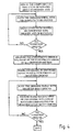
- Figure 4 illustrates the steps of a method of grinding one component having a number of cylindrical surfaces which are to be ground concentric to the primary axis of the component. The same process is followed for each component to be ground.
Landscapes
- Engineering & Computer Science (AREA)
- Human Computer Interaction (AREA)
- Manufacturing & Machinery (AREA)
- Physics & Mathematics (AREA)
- General Physics & Mathematics (AREA)
- Automation & Control Theory (AREA)
- Grinding Of Cylindrical And Plane Surfaces (AREA)
- Constituent Portions Of Griding Lathes, Driving, Sensing And Control (AREA)
- Electrical Discharge Machining, Electrochemical Machining, And Combined Machining (AREA)
Claims (12)
- Verfahren zum Einrichten einer rechnergesteuerten Schleifmaschine, mit einer Schleifscheibe (12) zum konzentrischen Schleifen eines externen zylindrischen Bereiches (31) eines Werkstückes, dadurch gekennzeichnet, dass ein Daten über das Werkstück enthaltendes Programm und ein Instruktionen über den Scheibenvorschub enthaltendes Programm geladen wird, die Instruktionen des Scheibenvorschubprogramms so abgearbeitet werden, dass der Werkstückbereich geschliffen wird, die Schleifscheibe (12) außer Eingriff gebracht wird, jede unerwünschte Exzentrizität, die durch den Schleifvorgang zusammen mit deren Winkelposition in den Bereich eingeführt wird, gemessen wird (34), und die Schleifscheibenvorschubprogramm-Instruktionen oder Steuersignale so eingestellt werden, dass korrigierte Schleifscheibenvorschubprogramm-Instruktionen oder Steuersignale gebildet werden, derart, dass während des nachfolgenden Schleifvorganges dieses Bereiches oder ähnlicher Bereiche ähnlicher Werkstücke der Schleifscheibenvorschub so gesteuert wird, dass eine komplementäre Exzentrizität erzeugt wird, damit die gemessene unerwünschte Exzentrizität kompensiert wird.
- Verfahren nach Anspruch 1, dadurch gekennzeichnet, dass das Messen des Werkstückbereiches (31) vorgenommen wird, nachdem das Werkstück entlastet worden ist.
- Verfahren nach Anspruch 1 oder 2 für ein längliches Werkstück, das eine Vielzahl solcher Bereiche (31) enthält, die an in axialer Richtung voneinander beabstandeten Positionen geschliffen werden sollen, und das an entgegengesetzten Enden (24, 26) abgestützt ist, dadurch gekennzeichnet, dass die Messungen, die den Einrichtprozess betreffen, an einem konzentrischen zylindrischen Bereich etwa in der Mitte der axialen Länge des Werkstückes vorgenommen werden, und proportional reduzierte Korrekturen den Schleifscheibenvorschubprogramm-Instruktionen oder Steuersignalen aufgegeben werden, die für ähnliche zu schleifende Bereiche (31) verwendet werden, und die aus der Mittenposition gegen das eine oder das andere der abgestützten Enden des Werkstückes verschoben werden.
- Verfahren nach Anspruch 1 oder 2 für ein längliches Werkstück, das an entgegengesetzten Enden (24, 26) abgestützt wird, bei dem eine unerwünschte Exzentrizität, die durch die beim Schleifvorgang auftretenden Kräfte entsteht, im Ausmaß längs der axialen Länge, gemessen in bezug auf die abgestützten Enden, variieren kann, derart, dass Bereiche (31) zur Mitte des Werkstückes hin ein größeres Maß an Kompensation der Exzentrizität während des Schleifens im Vergleich zu den den Enden benachbarten Bereichen erforderlich macht, dadurch gekennzeichnet, dass ferner alle zylindrischen Oberflächen eines Werkstückes, die mit der primären Werkstückachse konzentrisch verlaufen sollen, zylindrisch geschliffen werden, ohne dass eine Kompensation einer unerwünschten, durch die beim Schleifvorgang auftretenden Kräfte eingeführten Exzentrizität durchgeführt wird, dass anschließend Messungen an dem Werkstück vorgenommen werden, um jede unerwünschte Exzentrizität sowie deren Winkelposition um die primäre Werkstückachse der Rotation für jeden der geschliffenen Bereiche festzustellen, und dass alle Schleifscheibenvorschubprogramm-Instruktionen oder Steuersignale getrennt eingestellt werden, um korrigierte Schleifscheibenvorschubprogramm-Instruktionen oder Steuersignale zu bilden, die zur Steuerung des Schleifscheibenvorschubs während des nachfolgenden Schleifens des oder eines anderen ähnlichen Werkstückes an jedem der entsprechenden Bereiche verwendet werden, so dass individuell jede der durch den Bearbeitungsvorgang entstandenen Exzentrizitäten in jedem Bereich kompensiert wird.
- Verfahren nach einem der Ansprüche 1 - 4, dadurch gekennzeichnet, dass nach dem Durchführen des Einrichtvorganges und nachdem das ursprüngliche Werkstück unter Verwendung der korrigierten Schleifscheibenvorschubprogramm-Instruktionen oder Steuersignale nachgeschliffen worden ist, ein weiterer Messvorgang (34) des nachgeschliffenen Werkstückes vorgenommen wird, und dass Korrekturen zweiter Ordnung an den Schleifscheibenvorschubprogramm-Instruktionen oder Steuersignalen vorgenommen werden, bevor weitere Werkstücke geschliffen werden.
- Verfahren nach einem der Ansprüche 1 - 5, dadurch gekennzeichnet, dass nach dem Einstellen der Schleifscheibenvorschubprogramm-Instruktionen oder Steuersignale der Schleifscheibenvorschub-Antrieb (22) anschließend mit Hilfe der korrigierten Schleifscheibenvorschubprogramm-Instruktionen oder Steuersignale so gesteuert wird, dass Werkstücke ähnlich dem während des Einrichtens benutzten geschliffen werden.
- Verfahren nach einem der Ansprüche 1 - 5, dadurch gekennzeichnet, dass anstelle des Herstellens nur eines Werkstückes (31), an dem Messungen während des Einrichtens vorgenommen werden, in jeder Stufe eine Mehrzahl von Werkstücken geschliffen werden, die miteinander ein Muster bilden, und Exzentrizitätsmessungen an allen Werkstücken in jedem Muster vorgenommen werden, wodurch das Ausmaß unerwünschter Exzentrizität sowohl in bezug auf die Winkelposition als auch die radiale Erstreckung für jeden Bereich eines jeden Werkstückes in jedem Muster festgestellt wird, und die mittlere unerwünschte Exzentrizität sowie die mittlere Winkelposition einer solchen Exzentrizität für jedes Muster zur Verwendung als Basis für die korrigierten Schleifscheibenvorschubprogramm-lnstruktionen oder Steuersignale bestimmt wird.
- Verfahren zum Schleifen von konzentrischen zylindrischen Bereichen (31) ähnlicher Werkstücke, dadurch gekennzeichnet, dass eine rechnergesteuerte Schleifmaschine nach einem Verfahren entsprechend einem der Ansprüche 1 - 7 eingerichtet wird, und dass anschließend zylindrische Bereiche (31) von Werkstücken ähnlich denen, die bei dem Einrichtvorgang verwendet werden, geschliffen werden, indem die korrigierten Schleifscheibenvorschubprogramm-Instruktionen oder Steuersignale verwendet werden, die aus dem Einricht-Vorgang abgeleitet werden, um den Schleifscheibenvorschub-Antrieb (22) während eines jeden Schleifvorganges. zu steuern.
- Verfahren nach einem der Ansprüche 1 - 8, dadurch gekennzeichnet, dass in verkleinertem Maßstab ein durch Software gesteuerter Kurbelzapfen entsprechend einer Ausrüstung, die in eine rechnergesteuerte Schleifmaschine eingebaut ist, verwendet wird, wodurch ermöglicht wird, dass eine Schleifscheibe der relativ großen exzentrischen Bewegung eines Kurbelzapfens während des Schleifens bei rotierender Kurbelwelle folgt, um die unerwünschte Exzentrizität zu kompensieren, die in die zylindrisch geschliffenen Oberflächen der Kurbelwelle als Folge von auf dem Schleifvorgang beruhenden Kräften eingeführt wird, die beim Schleifen solcher Flächen ausgeübt werden, und die auftreten, nachdem das Werkstück entlastet worden ist.
- Verfahren nach Anspruch 8, bei dem der Schleifscheibenvorschub-Antrieb (22) zwei Betriebsarten umfasst, nämlich eine erste Betriebsart für normalen Vorschub und Zurückziehen, und eine zweite Betriebsart, in der sehr kleine, jedoch präzise Einstellungen auf die augenblickliche Schleifscheibenposition durchgeführt werden, so dass während des Schleifens und während die Scheibe (12) in Kontakt mit dem Werkstück steht und ein Oberflächenschleifen durchgeführt wird, die Scheibe um sehr kleine Beträge synchron und in entsprechender Phase mit der Drehung des Werkstückes nach rückwärts und vorwäts bewegt werden kann, indem die korrigierten Schleifscheibenvorschubprogramm-lnstruktionen oder Steuersignale verwendet werden, um jede Exzentrizität zu kompensieren, die sonst bei dem Schleifvorgang des Werkstückbereiches aufgrund von Kräften, die während des Schleifvorganges entstehen, auftreten würden.
- Rechnergesteuerte Schleifmaschine zur Durchführung des Verfahrens zum Schleifen nach einem der Ansprüche 1 - 10, gekennzeichnet durch eine Schleifscheibe (12), eine Antriebsvorrichtung (14) zum Rotieren der Schleifscheibe, eine Schleifscheibenvorschub- Antriebsvorrichtung (22) zum präzisen Vorschieben und Zurückziehen der Schleifscheibe (12) auf einen externen zylindrischen Bereich (31) eines Werkstückes zu und von ihm weg, einen Rechner (32) zur Steuerung der Schleifscheibenvorschub-Antriebsvorrichtung, die eine erste Speichervorrichtung zur Speicherung programmierbarer Schleifscheibenvorschub-Instruktionen aufweist, durch die die Position der Schleifscheibe (12) in jedem Augenblick während eines Schleifvorganges gesteuert werden kann, ein Programm, das in den Rechner (32) geladen wird, um den Vorschub und das Zurückziehen sowie das Positionieren der Schleifscheibe zu steuem, eine Messvorrichtung (34), die mit dem Rechner verbunden ist, um die unerwünschte Exzentrizität und deren Winkelposition zu messen, während die Schleifscheibe außer Eingriff steht, und eine zweite Speichervorrichtung zur Speicherung von Korrektursignalen, die aus der Messvorrichtung zur Einstellung der ursprünglichen Schleifscheibenvorschub-Instruktionen während des Schleifens der Bereiche (31) abgeleitet werden, oder zur Speicherung der korrigierten Schleifscheibenvorschubprogramm-lnstruktionen oder Steuersignale, so dass eine komplementäre Exzentrizität in diesem Bereich (31) erzeugt wird.
- Maschine nach Anspruch 11, die programmiert einen Schleifvorgang durchführt, der unerwünschte Exzentrizitäten reduziert, die durch die während des Schleifvorganges auftretenden Kräfte in einen konzentrischen zylindrischen WerkstückBereich (31) eingeführt werden, indem jeder dieser Bereiche so geschliffen wird, als ob er komplementär exzentrisch zu einer Exzentrizität ist, die durch die beim Schleifvorgang auftretenden Kräfte eingeführt wird.
Priority Applications (1)
| Application Number | Priority Date | Filing Date | Title |
|---|---|---|---|
| EP99119668A EP0974883B1 (de) | 1996-04-23 | 1997-04-22 | Verfahren und Vorrichtung zum konzentrischen Schleifen von zylindrischen Werkstückbereichen |
Applications Claiming Priority (3)
| Application Number | Priority Date | Filing Date | Title |
|---|---|---|---|
| GBGB9608352.2A GB9608352D0 (en) | 1996-04-23 | 1996-04-23 | Workpiece grinding method and apparatus |
| GB9608352 | 1996-04-23 | ||
| PCT/GB1997/001110 WO1997040434A1 (en) | 1996-04-23 | 1997-04-22 | Methods and apparatus for grinding concentric cylindrical workpiece regions |
Related Child Applications (1)
| Application Number | Title | Priority Date | Filing Date |
|---|---|---|---|
| EP99119668A Division EP0974883B1 (de) | 1996-04-23 | 1997-04-22 | Verfahren und Vorrichtung zum konzentrischen Schleifen von zylindrischen Werkstückbereichen |
Publications (2)
| Publication Number | Publication Date |
|---|---|
| EP0895615A1 EP0895615A1 (de) | 1999-02-10 |
| EP0895615B1 true EP0895615B1 (de) | 2001-10-17 |
Family
ID=10792484
Family Applications (2)
| Application Number | Title | Priority Date | Filing Date |
|---|---|---|---|
| EP97919519A Expired - Lifetime EP0895615B1 (de) | 1996-04-23 | 1997-04-22 | Verfahren und vorrichtung zum schleifen von konzentrisch zylindrischen bereichen von werkstücken |
| EP99119668A Expired - Lifetime EP0974883B1 (de) | 1996-04-23 | 1997-04-22 | Verfahren und Vorrichtung zum konzentrischen Schleifen von zylindrischen Werkstückbereichen |
Family Applications After (1)
| Application Number | Title | Priority Date | Filing Date |
|---|---|---|---|
| EP99119668A Expired - Lifetime EP0974883B1 (de) | 1996-04-23 | 1997-04-22 | Verfahren und Vorrichtung zum konzentrischen Schleifen von zylindrischen Werkstückbereichen |
Country Status (6)
| Country | Link |
|---|---|
| EP (2) | EP0895615B1 (de) |
| AU (1) | AU2395997A (de) |
| DE (2) | DE69707438T2 (de) |
| ES (2) | ES2166076T3 (de) |
| GB (2) | GB9608352D0 (de) |
| WO (1) | WO1997040434A1 (de) |
Families Citing this family (10)
| Publication number | Priority date | Publication date | Assignee | Title |
|---|---|---|---|---|
| IT1279641B1 (it) | 1995-10-03 | 1997-12-16 | Marposs Spa | Apparecchio per il controllo del diametro di perni di biella in moto orbitale |
| GB9608351D0 (en) * | 1996-04-23 | 1996-06-26 | Western Atlas Uk Ltd | Composite component grinding method and apparatus |
| GB2318074B (en) * | 1996-04-23 | 1999-07-28 | Unova Uk Ltd | Method and apparatus for grinding composite workpieces |
| GB2317130B (en) * | 1996-09-13 | 1999-01-06 | Western Atlas Uk Ltd | Improvements in and relating to workpiece grinding |
| JP4487387B2 (ja) | 1999-06-25 | 2010-06-23 | 株式会社ジェイテクト | 真円度測定装置 |
| GB9928825D0 (en) * | 1999-12-06 | 2000-02-02 | Unova Uk Ltd | Improvements in and relating to grinding |
| IT1321211B1 (it) | 2000-03-06 | 2003-12-31 | Marposs Spa | Apparecchiatura e metodo per il controllo di perni . |
| DE102010035147B4 (de) | 2010-08-23 | 2016-07-28 | Jenoptik Industrial Metrology Germany Gmbh | Meßvorrichtung |
| GB201108845D0 (en) * | 2011-05-26 | 2011-07-06 | Cinetic Landis Ltd | Machine tools and methods of operating thereof |
| DE102012018580B4 (de) | 2012-09-20 | 2015-06-11 | Jenoptik Industrial Metrology Germany Gmbh | Messvorrichtung und Messverfahren zur Inprozess-Messung an Prüflingen während eines Bearbeitungsvorganges an einer Bearbeitungsmaschine, insbesondere einer Schleifmaschine |
Family Cites Families (7)
| Publication number | Priority date | Publication date | Assignee | Title |
|---|---|---|---|---|
| JPS5244668B2 (de) * | 1973-09-08 | 1977-11-09 | ||
| DE2918249A1 (de) * | 1979-05-05 | 1980-11-06 | Goetze Ag | Maschine zum vorzugsweise spanenden umfangsbearbeiten von unrunden werkstuecken, insbesondere kolbenringen |
| JPS58192750A (ja) * | 1982-05-03 | 1983-11-10 | Toyoda Mach Works Ltd | 研削盤 |
| DE3702594C3 (de) * | 1987-01-29 | 1995-04-06 | Fortuna Werke Maschf Ag | Verfahren und Vorrichtung zum Schleifen von Nocken an Nockenwellen |
| DE3707326A1 (de) * | 1987-03-07 | 1988-09-15 | Gehring Gmbh Maschf | Honverfahren |
| JPH01147608A (ja) * | 1987-12-02 | 1989-06-09 | Toshiba Mach Co Ltd | 位置決め誤差補正方式 |
| US5419222A (en) * | 1992-10-08 | 1995-05-30 | The United States Of America As Represented By The United States Department Of Energy | Method for measuring the contour of a machined part |
-
1996
- 1996-04-23 GB GBGB9608352.2A patent/GB9608352D0/en active Pending
-
1997
- 1997-04-22 GB GB9708198A patent/GB2312387B/en not_active Expired - Fee Related
- 1997-04-22 EP EP97919519A patent/EP0895615B1/de not_active Expired - Lifetime
- 1997-04-22 ES ES97919519T patent/ES2166076T3/es not_active Expired - Lifetime
- 1997-04-22 WO PCT/GB1997/001110 patent/WO1997040434A1/en not_active Ceased
- 1997-04-22 DE DE69707438T patent/DE69707438T2/de not_active Expired - Fee Related
- 1997-04-22 DE DE1997615464 patent/DE69715464T2/de not_active Expired - Fee Related
- 1997-04-22 AU AU23959/97A patent/AU2395997A/en not_active Abandoned
- 1997-04-22 EP EP99119668A patent/EP0974883B1/de not_active Expired - Lifetime
- 1997-04-22 ES ES99119668T patent/ES2184377T3/es not_active Expired - Lifetime
Also Published As
| Publication number | Publication date |
|---|---|
| GB2312387A (en) | 1997-10-29 |
| EP0974883B1 (de) | 2002-09-11 |
| GB9708198D0 (en) | 1997-06-11 |
| DE69707438D1 (de) | 2001-11-22 |
| AU2395997A (en) | 1997-11-12 |
| ES2184377T3 (es) | 2003-04-01 |
| ES2166076T3 (es) | 2002-04-01 |
| EP0974883A1 (de) | 2000-01-26 |
| GB2312387B (en) | 1999-07-28 |
| DE69715464D1 (de) | 2002-10-17 |
| WO1997040434A1 (en) | 1997-10-30 |
| DE69707438T2 (de) | 2002-05-29 |
| EP0895615A1 (de) | 1999-02-10 |
| GB9608352D0 (en) | 1996-06-26 |
| DE69715464T2 (de) | 2003-01-09 |
Similar Documents
| Publication | Publication Date | Title |
|---|---|---|
| US6411861B1 (en) | Method and apparatus for grinding composite workpieces | |
| EP1193028B1 (de) | Messverfahren für Werkstückteil und Bearbeitungsverfahren | |
| US5251405A (en) | Method for circumferential grinding of radially non-circular workpieces | |
| US6038489A (en) | Machine tools | |
| US5103596A (en) | Method and apparatus for controlling cylinder grinding machines | |
| EP0895615B1 (de) | Verfahren und vorrichtung zum schleifen von konzentrisch zylindrischen bereichen von werkstücken | |
| US5919081A (en) | Method and apparatus for computer numerically controlled pin grinder gauge | |
| EP1736278B1 (de) | Schleifverfahren | |
| US4831787A (en) | Honing process | |
| EP0950214B1 (de) | Verfahren zur steuerung einer werkzeugmaschine | |
| GB2318074A (en) | Compensating for grinding inaccuracies | |
| EP0791873B1 (de) | Schleifverfahren und -vorrichtung für zylindrische Werkstücke | |
| DE69704165T2 (de) | Verbesserungen in/oder bezüglich werkstückschleifen | |
| JP2542084B2 (ja) | 研削砥石の研削面修正方法 | |
| KR940008088B1 (ko) | 수치 제어 공작 기계 및 그 연삭 동작 제어 방법 | |
| JPH11282519A (ja) | 研削盤用数値制御装置および研削方法 | |
| JPH05162068A (ja) | 内面研削におけるリトラクション量調整方法 | |
| GB2351685A (en) | Workrest control in a multi-wheel grinding machine | |
| JP2000033547A (ja) | Cnc研削盤による研削方法 | |
| JPH04136658U (ja) | 研削装置 |
Legal Events
| Date | Code | Title | Description |
|---|---|---|---|
| PUAI | Public reference made under article 153(3) epc to a published international application that has entered the european phase |
Free format text: ORIGINAL CODE: 0009012 |
|
| 17P | Request for examination filed |
Effective date: 19980921 |
|
| AK | Designated contracting states |
Kind code of ref document: A1 Designated state(s): DE ES FR IT |
|
| 17Q | First examination report despatched |
Effective date: 19990817 |
|
| GRAG | Despatch of communication of intention to grant |
Free format text: ORIGINAL CODE: EPIDOS AGRA |
|
| GRAG | Despatch of communication of intention to grant |
Free format text: ORIGINAL CODE: EPIDOS AGRA |
|
| GRAH | Despatch of communication of intention to grant a patent |
Free format text: ORIGINAL CODE: EPIDOS IGRA |
|
| GRAH | Despatch of communication of intention to grant a patent |
Free format text: ORIGINAL CODE: EPIDOS IGRA |
|
| ITF | It: translation for a ep patent filed | ||
| GRAA | (expected) grant |
Free format text: ORIGINAL CODE: 0009210 |
|
| AK | Designated contracting states |
Kind code of ref document: B1 Designated state(s): DE ES FR IT |
|
| REF | Corresponds to: |
Ref document number: 69707438 Country of ref document: DE Date of ref document: 20011122 |
|
| ET | Fr: translation filed | ||
| REG | Reference to a national code |
Ref country code: ES Ref legal event code: FG2A Ref document number: 2166076 Country of ref document: ES Kind code of ref document: T3 |
|
| PLBE | No opposition filed within time limit |
Free format text: ORIGINAL CODE: 0009261 |
|
| STAA | Information on the status of an ep patent application or granted ep patent |
Free format text: STATUS: NO OPPOSITION FILED WITHIN TIME LIMIT |
|
| 26N | No opposition filed | ||
| REG | Reference to a national code |
Ref country code: FR Ref legal event code: TP |
|
| PGFP | Annual fee paid to national office [announced via postgrant information from national office to epo] |
Ref country code: FR Payment date: 20080313 Year of fee payment: 12 Ref country code: ES Payment date: 20080418 Year of fee payment: 12 Ref country code: DE Payment date: 20080320 Year of fee payment: 12 |
|
| PGFP | Annual fee paid to national office [announced via postgrant information from national office to epo] |
Ref country code: IT Payment date: 20080331 Year of fee payment: 12 |
|
| REG | Reference to a national code |
Ref country code: FR Ref legal event code: CD |
|
| REG | Reference to a national code |
Ref country code: FR Ref legal event code: ST Effective date: 20091231 |
|
| PG25 | Lapsed in a contracting state [announced via postgrant information from national office to epo] |
Ref country code: DE Free format text: LAPSE BECAUSE OF NON-PAYMENT OF DUE FEES Effective date: 20091103 |
|
| PG25 | Lapsed in a contracting state [announced via postgrant information from national office to epo] |
Ref country code: FR Free format text: LAPSE BECAUSE OF NON-PAYMENT OF DUE FEES Effective date: 20091222 |
|
| REG | Reference to a national code |
Ref country code: ES Ref legal event code: FD2A Effective date: 20090423 |
|
| PG25 | Lapsed in a contracting state [announced via postgrant information from national office to epo] |
Ref country code: ES Free format text: LAPSE BECAUSE OF NON-PAYMENT OF DUE FEES Effective date: 20090423 |
|
| PG25 | Lapsed in a contracting state [announced via postgrant information from national office to epo] |
Ref country code: IT Free format text: LAPSE BECAUSE OF NON-PAYMENT OF DUE FEES Effective date: 20090422 |