EP0894871B1 - Apparatus for drying sugar cubes - Google Patents
Apparatus for drying sugar cubes Download PDFInfo
- Publication number
- EP0894871B1 EP0894871B1 EP98201721A EP98201721A EP0894871B1 EP 0894871 B1 EP0894871 B1 EP 0894871B1 EP 98201721 A EP98201721 A EP 98201721A EP 98201721 A EP98201721 A EP 98201721A EP 0894871 B1 EP0894871 B1 EP 0894871B1
- Authority
- EP
- European Patent Office
- Prior art keywords
- sugar cubes
- microwave
- producing
- microwave cavity
- drying
- Prior art date
- Legal status (The legal status is an assumption and is not a legal conclusion. Google has not performed a legal analysis and makes no representation as to the accuracy of the status listed.)
- Expired - Lifetime
Links
- 238000001035 drying Methods 0.000 title claims description 33
- 238000010438 heat treatment Methods 0.000 claims description 20
- 230000003750 conditioning effect Effects 0.000 claims description 8
- 238000001816 cooling Methods 0.000 claims description 6
- 230000008878 coupling Effects 0.000 claims description 3
- 238000010168 coupling process Methods 0.000 claims description 3
- 238000005859 coupling reaction Methods 0.000 claims description 3
- 238000007599 discharging Methods 0.000 claims description 2
- 229920002994 synthetic fiber Polymers 0.000 claims description 2
- XLYOFNOQVPJJNP-UHFFFAOYSA-N water Substances O XLYOFNOQVPJJNP-UHFFFAOYSA-N 0.000 description 4
- 230000008901 benefit Effects 0.000 description 3
- 238000009826 distribution Methods 0.000 description 3
- 238000004806 packaging method and process Methods 0.000 description 3
- 230000015556 catabolic process Effects 0.000 description 2
- 238000007602 hot air drying Methods 0.000 description 2
- 238000007603 infrared drying Methods 0.000 description 2
- 230000009471 action Effects 0.000 description 1
- 238000009833 condensation Methods 0.000 description 1
- 230000005494 condensation Effects 0.000 description 1
- 238000010276 construction Methods 0.000 description 1
- 230000009849 deactivation Effects 0.000 description 1
- 230000006872 improvement Effects 0.000 description 1
- 239000000203 mixture Substances 0.000 description 1
- 230000001681 protective effect Effects 0.000 description 1
- 230000008439 repair process Effects 0.000 description 1
- 238000009827 uniform distribution Methods 0.000 description 1
Images


Classifications
-
- C—CHEMISTRY; METALLURGY
- C13—SUGAR INDUSTRY
- C13B—PRODUCTION OF SUCROSE; APPARATUS SPECIALLY ADAPTED THEREFOR
- C13B40/00—Drying sugar
- C13B40/007—Drying sugar in compacted form, e.g. cubes
Definitions
- the present invention relates to an apparatus for drying sugar cubes as described in the preamble of claim 1.
- Such an apparatus is known from DE-C- 924.860.
- the present invention provides a device for drying sugar cubes containing a heating apparatus for heating and dehumidifying the sugar cubes, a conditioning apparatus for cooling off and possibly further dehumidifying the sugar cubes and a conveying apparatus for conveying the sugar cubes through the heating apparatus and the conditioning apparatus, in which the heating apparatus comprises a multimode microwave cavity and a number of microwave heads which are connected to the microwave cavity by their own wave-guide. Because drying the sugar cubes takes place by microwave energy generated by the microwave heads, compared to the known drying devices a homogenous heating of the whole sugar cube takes place in which most of the humidity in the sugar cube is released, thus saving between 30% and 50% of the energy.
- the length of the drying route can be reduced to approximately 15% compared to hot air and infrared drying.
- the microwave cavity is a multimode microwave cavity, that is that a number of microwave heads are provided, for instance up to 30 or more, it is possible to adjust the generated energy in an optimum manner to the sugar cubes in the microwave cavity.
- a further advantage of the multimode microwave cavity is that the distribution of field intensity over the width and length of the cavity can be very even, so that as a consequence all the cubes are supplied with the same amount of energy, as a result of which all the cubes have a same even temperature and humidity content at the end of the microwave cavity.
- each wave-guide is provided at the location of the microwave cavity with slots for coupling microwave energy in the microwave cavity, the field intensity can be optimally distributed in the microwave cavity, because of the size, the angle of canting and the mutual positioning of the grooves.
- each microwave head has a defined capacity, so that the field intensity in the microwave cavity can be varied accordingly.
- a further embodiment of the invention according to the invention contains a sensor for detecting the number of rows of sugar cubes conveyed by the conveying apparatus into the microwave cavity, a field intensity meter for measuring the field intensity in the microwave cavity and a velocity meter for measuring the conveying velocity of the sugar cubes, as a result of which an exact adjustment and control of the drying process is obtained.
- a humidity sensor placed in the microwave cavity can further improve this control.
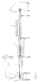
- FIG 1 a device for producing and drying sugar cubes is schematically shown in side view, which device is made in a usual line layout.
- Sugar and water are supplied in the usual way to a press 1, in which the sugar and the water are mixed and in which the sugar cubes are pressed into the correct shape, size and weight. From the press the sugar cubes are conveyed via a conveying apparatus 2 to the heating apparatus 3.
- the heating apparatus 3 contains a multimode microwave cavity 19 (figure 2) and a number of microwave heads 10 (figure 3).
- the conveying apparatus 2 conveys the wet sugar cubes 13 through the microwave cavity 19, where the sugar cubes 13 are heated by microwave energy to a temperature of approximately 75°C and most of the humidity in the sugar cubes 13 is released. Because of this the sugar cubes 13 get enough latent energy to arrive at the desired final humidity content in a conditioning apparatus 4 (figure 1).
- a conditioning apparatus 4 (figure 1).
- the press 1, the conveying apparatus 2 and the packaging apparatus 5 are electrically driven in the known manner, the drives being adapted to one another.
- the conveying apparatus 2 is preferably a conveyor belt made of synthetic material, the dielectric characteristics of which being such, that the conveyor belt takes up as little energy as possible.
- the heating apparatus 3 contains a number of microwave heads 10 which are connected to the microwave cavity by their own wave-guide 17 (figure 3).
- the wave-guides are placed horizontally, transverse to the direction of conveyance, with the microwave heads at the ends of the wave-guides.
- the microwave heads can be placed directly under the stream of sugar cubes, the microwave heads being connected with vertical wave-guides to the microwave cavity.
- This last alternative embodiment provides a more compact construction form and a good heating of the sugar cubes, which is almost independent of the height of the sugar cubes.
- the number of microwave heads is five, although in practise up to thirty or more heads can be used.
- the microwave heads are, for instance, are standard industrial heads with a capacity of 1.2 kW, for example.
- Each wave-guide 17 is provided at the location of the microwave cavity with slots 18 for coupling the microwave energy in the microwave cavity.
- the size, position and mutual positioning of the slots 18 can be chosen to obtain a desired field intensity distribution in the microwave cavity.
- each microwave head has a defined capacity, or an independent capacity adjustment in order to further distribute the field intensity as desired.
- the action of the inventive drying device is improved with regard to the known devices, namely in startup and stop situations.
- the microwave cavity will slowly be filled with sugar cubes.
- An adjustment of this kind can be controlled by the sensor 12 at a known conveying velocity.
- a stop situation for instance when there is a breakdown, the energy supply to the microwave heads can be switched off immediately, as a result of which heating does not take place either.
- the microwave cavity then cools off immediately. Problems such as caramelization or discolouring do not therefore occur and repairs can be speedily carried out.
- the microwave cavity 19 there are means, for example one or more ventilators 14, for extracting from the microwave cavity air in which humidity is included which is already leaving the sugar cubes 13.
- the conveyor belt is provided with air passages.
- a sensor 12 detects the number of rows of sugar cubes conveyed by the conveyor belt 2 into the microwave cavity, a field intensity meter 16 measures the field intensity in the microwave cavity 19 and, together with the velocity of the conveyor belt 2 measured by the velocity meter, the microwave heads are switched on or off so as to obtain a field intensity distribution desirable under the detected circumstances.
- the advantage of a multimode microwave cavity having suchlike adjustment, compared to using one large microwave source, is that an exact control of the drying process is obtained.
- a further improvement of the control of the drying process can be obtained by including a humidity sensor in the microwave cavity.
- a further advantage of a multimode microwave cavity is that there is a uniform distribution of the field intensity over the width and length of the microwave cavity, which results in the supply to all sugar cubes of the same quantity of energy, so that at the end of the microwave cavity all the sugar cubes have an equal temperature and an equal humidity content. As a consequence, all the sugar cubes will eventually have the same residual humidity content and the same hardness, which is important for packaging and further storage of the sugar cubes.
- the latter is provided with protective devices 15.
- the sugar cubes After the sugar cubes have passed through the microwave cavity, they are conveyed by the conveyor belt to and through the conditioning apparatus, where the sugar cubes are cooled by means of cooling means for generating air circulation. In addition, this air ensures the discharge of the humidity which may be leaving the sugar cubes. In that way the sugar cubes obtain the desired final humidity content and the desired hardness.
- this air is heated.
- This heated air can be led to the microwave cavity of the heating apparatus by means of tubes.
- the thermal energy of this air is then used for additional heating of the sugar cubes, this heated air also discharging humidity released in the microwave cavity and preventing condensation in the microwave cavity.
Landscapes
- Chemical & Material Sciences (AREA)
- Life Sciences & Earth Sciences (AREA)
- Biochemistry (AREA)
- Organic Chemistry (AREA)
- Drying Of Solid Materials (AREA)
Description
- The present invention relates to an apparatus for drying sugar cubes as described in the preamble of claim 1. Such an apparatus is known from DE-C- 924.860.
- When producing sugar cubes, a mixture of sugar and water is pressed to the desired shape, size and weight in a press. Usually, the water content amounts to approximately 1.2% this being reduced to about 0.4% by drying in a drying device. During drying the cubes not only achieve the desired final humidity content but also the required hardness so that they can be packed in boxes. Known drying devices are hot air or infrared drying devices. Suchlike devices frequently have a high energy expenditure and are large in size; drying lines of 40 metres are no exception. If a breakdown occurs in such a known drying device, the latter will only cool down slowly after the drying device has been deactivated. As a result, not only do problems such as caramelization or discolouring of the sugar cubes arise, but in addition to that it takes longer before the failure can be put right.
- It is an object of the invention to provide an apparatus for drying sugar cubes with a lower energy expenditure, in which the apparatus is also more compact and in which furthermore after deactivation, a faster cooling down of the apparatus can be realized.
- For this purpose the present invention provides a device for drying sugar cubes containing a heating apparatus for heating and dehumidifying the sugar cubes, a conditioning apparatus for cooling off and possibly further dehumidifying the sugar cubes and a conveying apparatus for conveying the sugar cubes through the heating apparatus and the conditioning apparatus, in which the heating apparatus comprises a multimode microwave cavity and a number of microwave heads which are connected to the microwave cavity by their own wave-guide. Because drying the sugar cubes takes place by microwave energy generated by the microwave heads, compared to the known drying devices a homogenous heating of the whole sugar cube takes place in which most of the humidity in the sugar cube is released, thus saving between 30% and 50% of the energy. In addition, the length of the drying route can be reduced to approximately 15% compared to hot air and infrared drying. Especially because the microwave cavity is a multimode microwave cavity, that is that a number of microwave heads are provided, for instance up to 30 or more, it is possible to adjust the generated energy in an optimum manner to the sugar cubes in the microwave cavity. A further advantage of the multimode microwave cavity is that the distribution of field intensity over the width and length of the cavity can be very even, so that as a consequence all the cubes are supplied with the same amount of energy, as a result of which all the cubes have a same even temperature and humidity content at the end of the microwave cavity.
- If each wave-guide is provided at the location of the microwave cavity with slots for coupling microwave energy in the microwave cavity, the field intensity can be optimally distributed in the microwave cavity, because of the size, the angle of canting and the mutual positioning of the grooves.
- In an embodiment of the apparatus according to the invention each microwave head has a defined capacity, so that the field intensity in the microwave cavity can be varied accordingly.
- A further embodiment of the invention according to the invention contains a sensor for detecting the number of rows of sugar cubes conveyed by the conveying apparatus into the microwave cavity, a field intensity meter for measuring the field intensity in the microwave cavity and a velocity meter for measuring the conveying velocity of the sugar cubes, as a result of which an exact adjustment and control of the drying process is obtained. A humidity sensor placed in the microwave cavity can further improve this control.
- Some embodiments of a device according to the invention will, by way of example, be described on the basis of the drawing, in which
- figure 1 shows a schematic side view of a device for producing and drying sugar cubes,
- figure 2 shows a schematic side view of the heating apparatus according to the invention, and
- figure 3 shows a schematic top view of the heating apparatus shown in figure 2.
-
- In figure 1 a device for producing and drying sugar cubes is schematically shown in side view, which device is made in a usual line layout. Sugar and water are supplied in the usual way to a press 1, in which the sugar and the water are mixed and in which the sugar cubes are pressed into the correct shape, size and weight. From the press the sugar cubes are conveyed via a conveying
apparatus 2 to theheating apparatus 3. - The
heating apparatus 3 contains a multimode microwave cavity 19 (figure 2) and a number of microwave heads 10 (figure 3). The conveyingapparatus 2 conveys thewet sugar cubes 13 through themicrowave cavity 19, where thesugar cubes 13 are heated by microwave energy to a temperature of approximately 75°C and most of the humidity in thesugar cubes 13 is released. Because of this thesugar cubes 13 get enough latent energy to arrive at the desired final humidity content in a conditioning apparatus 4 (figure 1). After the sugar cubes have been conveyed through the conditioning apparatus 4, they are conveyed to ausual packaging apparatus 5 by the conveyingapparatus 2, where the sugar cubes are packed in boxes or the like. The press 1, theconveying apparatus 2 and thepackaging apparatus 5 are electrically driven in the known manner, the drives being adapted to one another. - In order that as little microwave energy as possible is lost in the microwave cavity, the conveying
apparatus 2 is preferably a conveyor belt made of synthetic material, the dielectric characteristics of which being such, that the conveyor belt takes up as little energy as possible. - The
heating apparatus 3 contains a number ofmicrowave heads 10 which are connected to the microwave cavity by their own wave-guide 17 (figure 3). In the embodiment shown in the figures, the wave-guides are placed horizontally, transverse to the direction of conveyance, with the microwave heads at the ends of the wave-guides. Alternatively, the microwave heads can be placed directly under the stream of sugar cubes, the microwave heads being connected with vertical wave-guides to the microwave cavity. This last alternative embodiment provides a more compact construction form and a good heating of the sugar cubes, which is almost independent of the height of the sugar cubes. In addition, in the exemplary embodiment shown in the figures, the number of microwave heads is five, although in practise up to thirty or more heads can be used. The microwave heads are, for instance, are standard industrial heads with a capacity of 1.2 kW, for example. - Each wave-
guide 17 is provided at the location of the microwave cavity withslots 18 for coupling the microwave energy in the microwave cavity. The size, position and mutual positioning of theslots 18 can be chosen to obtain a desired field intensity distribution in the microwave cavity. Furthermore, each microwave head has a defined capacity, or an independent capacity adjustment in order to further distribute the field intensity as desired. - Because the microwave heads are independently adjustable, the action of the inventive drying device is improved with regard to the known devices, namely in startup and stop situations. When starting up the inventive device, the microwave cavity will slowly be filled with sugar cubes. In order to obtain a uniform drying process, in accordance with this several microwave heads are switched on upon starting up or more capacity is generated by the microwave heads. An adjustment of this kind can be controlled by the
sensor 12 at a known conveying velocity. In a stop situation, for instance when there is a breakdown, the energy supply to the microwave heads can be switched off immediately, as a result of which heating does not take place either. The microwave cavity then cools off immediately. Problems such as caramelization or discolouring do not therefore occur and repairs can be speedily carried out. - In the
microwave cavity 19 there are means, for example one ormore ventilators 14, for extracting from the microwave cavity air in which humidity is included which is already leaving thesugar cubes 13. In order to improve air circulation, the conveyor belt is provided with air passages. - A
sensor 12 detects the number of rows of sugar cubes conveyed by theconveyor belt 2 into the microwave cavity, afield intensity meter 16 measures the field intensity in themicrowave cavity 19 and, together with the velocity of theconveyor belt 2 measured by the velocity meter, the microwave heads are switched on or off so as to obtain a field intensity distribution desirable under the detected circumstances. The advantage of a multimode microwave cavity having suchlike adjustment, compared to using one large microwave source, is that an exact control of the drying process is obtained. A further improvement of the control of the drying process can be obtained by including a humidity sensor in the microwave cavity. - A further advantage of a multimode microwave cavity is that there is a uniform distribution of the field intensity over the width and length of the microwave cavity, which results in the supply to all sugar cubes of the same quantity of energy, so that at the end of the microwave cavity all the sugar cubes have an equal temperature and an equal humidity content. As a consequence, all the sugar cubes will eventually have the same residual humidity content and the same hardness, which is important for packaging and further storage of the sugar cubes.
- In order to prevent undesired microwave energy from leaving the
heating apparatus 3, the latter is provided withprotective devices 15. - After the sugar cubes have passed through the microwave cavity, they are conveyed by the conveyor belt to and through the conditioning apparatus, where the sugar cubes are cooled by means of cooling means for generating air circulation. In addition, this air ensures the discharge of the humidity which may be leaving the sugar cubes. In that way the sugar cubes obtain the desired final humidity content and the desired hardness.
- Given that the microwave heads are cooled by air, this air is heated. This heated air can be led to the microwave cavity of the heating apparatus by means of tubes. The thermal energy of this air is then used for additional heating of the sugar cubes, this heated air also discharging humidity released in the microwave cavity and preventing condensation in the microwave cavity.
- With the drying device according to the invention a drying process which is 85% faster in comparison to known drying devices is obtained, with an energy saving of 30 to 50%. Moreover, the floor surface required by the device is considerably reduced.
Claims (10)
- Apparatus for producing and drying sugar cubes to the desired final humidity content comprising:a press for producing the sugar cubes;a heating apparatus (3) for heating and dehumidifying a plurality of sugar cubes, said heating apparatus being placed downstream of said press;a conditioning apparatus (4) for cooling said plurality of sugar cubes;a conveying apparatus (2) for conveying said sugar cubes from said press and through said heating apparatus and said conditioning apparatus, characterized in that said heating apparatus (3) includes a multimode microwave cavity (19) and a plurality of microwave heads (10), each of said microwave heads connected to said same microwave cavity by its own wave-guide (17), each microwave head being independable adjustable.
- Apparatus for producing and drying sugar cubes according to claim 1, in which each wave-guide (17) is provided at the location of the microwave cavity with slots (18) for coupling microwave energy in the microwave cavity.
- Apparatus for producing and drying sugar cubes according to claim 1 or 2, in which each microwave head has a defined capacity.
- Apparatus for producing and drying sugar cubes according to claim 1, 2 or 3, in which the microwave cavity (19) contains means (14) for discharging air and moisture out of there.
- Apparatus for producing and drying sugar cubes according to any one of the preceding claims, in which the device is provided with a sensor (12) for detecting the number of rows of sugar cubes conveyed by the conveying apparatus into the microwave cavity (19), a field intensity meter (16) for measuring the field intensity in the microwave cavity and a velocity meter for measuring the conveying velocity of the sugar cubes.
- Apparatus for producing and drying sugar cubes according to any one of the preceding claims, in which the microwave cavity (19) is provided with a humidity sensor.
- Apparatus for producing and drying sugar cubes according to any one of the preceding claims, in which the conditioning apparatus (4) is provided with cooling means for cooling the sugar cubes by means of air circulation.
- Apparatus for producing and drying sugar cubes according to any one of the preceding claims, in which the conveying apparatus (2) is a conveying belt made of synthetic material which absorbs almost no microwave energy.
- Apparatus for producing and drying sugar cubes according to claim 8, in which the conveyor belt (2) is provided with air passages.
- Apparatus according to any one of the preceding claims, wherein the microwave heads (10) are placed directly under the stream of sugar cubes, the microwave heads (10) being connected with vertical waveguides to the microwave cavity.
Priority Applications (1)
| Application Number | Priority Date | Filing Date | Title |
|---|---|---|---|
| DK98201721T DK0894871T3 (en) | 1997-06-03 | 1998-05-26 | Device for drying sugar cubes |
Applications Claiming Priority (2)
| Application Number | Priority Date | Filing Date | Title |
|---|---|---|---|
| NL1006216 | 1997-06-03 | ||
| NL1006216A NL1006216C2 (en) | 1997-06-03 | 1997-06-03 | Device for drying sugar cubes. |
Publications (2)
| Publication Number | Publication Date |
|---|---|
| EP0894871A1 EP0894871A1 (en) | 1999-02-03 |
| EP0894871B1 true EP0894871B1 (en) | 2004-08-18 |
Family
ID=19765088
Family Applications (1)
| Application Number | Title | Priority Date | Filing Date |
|---|---|---|---|
| EP98201721A Expired - Lifetime EP0894871B1 (en) | 1997-06-03 | 1998-05-26 | Apparatus for drying sugar cubes |
Country Status (6)
| Country | Link |
|---|---|
| EP (1) | EP0894871B1 (en) |
| DE (1) | DE69825688T2 (en) |
| DK (1) | DK0894871T3 (en) |
| ES (1) | ES2227765T3 (en) |
| NL (1) | NL1006216C2 (en) |
| TR (1) | TR199800989A2 (en) |
Cited By (2)
| Publication number | Priority date | Publication date | Assignee | Title |
|---|---|---|---|---|
| EP2481820A1 (en) | 2011-01-28 | 2012-08-01 | CFS Weert B.V. | Apparatus for drying sugar cubes with microwave radiation |
| EP2497838A1 (en) | 2011-03-11 | 2012-09-12 | GEA CFS Weert B.V. | Apparatus for producing sugar cubes |
Family Cites Families (4)
| Publication number | Priority date | Publication date | Assignee | Title |
|---|---|---|---|---|
| DE924860C (en) * | 1952-12-31 | 1955-03-07 | Rudolf Carl Bremer | Method and device for drying sugar in body form by means of high frequency |
| US4294624A (en) * | 1980-03-14 | 1981-10-13 | Veltman Preston Leonard | Drying co-mingled carbohydrate solution and recycled product by dielectric heating |
| NL8001629A (en) * | 1980-03-19 | 1981-10-16 | Stork Bepak Bv | METHOD AND APPARATUS FOR TRANSPORTING BLOCKS FROM A FORMING MACHINE FOR CONDITIONING |
| JPS6259000A (en) * | 1985-09-06 | 1987-03-14 | 株式会社 石野製作所 | Production of cube sugar |
-
1997
- 1997-06-03 NL NL1006216A patent/NL1006216C2/en not_active IP Right Cessation
-
1998
- 1998-05-26 DE DE1998625688 patent/DE69825688T2/en not_active Expired - Lifetime
- 1998-05-26 DK DK98201721T patent/DK0894871T3/en active
- 1998-05-26 ES ES98201721T patent/ES2227765T3/en not_active Expired - Lifetime
- 1998-05-26 EP EP98201721A patent/EP0894871B1/en not_active Expired - Lifetime
- 1998-06-02 TR TR1998/00989A patent/TR199800989A2/en unknown
Non-Patent Citations (1)
| Title |
|---|
| KOHLRAUSH F.: "Praktische Physik, Vol. 2", 1985, B.G. TEUBNER, STUTTGART, GART * |
Cited By (3)
| Publication number | Priority date | Publication date | Assignee | Title |
|---|---|---|---|---|
| EP2481820A1 (en) | 2011-01-28 | 2012-08-01 | CFS Weert B.V. | Apparatus for drying sugar cubes with microwave radiation |
| EP2497838A1 (en) | 2011-03-11 | 2012-09-12 | GEA CFS Weert B.V. | Apparatus for producing sugar cubes |
| WO2012123083A1 (en) | 2011-03-11 | 2012-09-20 | Gea Cfs Weert B.V. | Apparatus for producing sugar cubes |
Also Published As
| Publication number | Publication date |
|---|---|
| TR199800989A2 (en) | 1998-12-21 |
| EP0894871A1 (en) | 1999-02-03 |
| ES2227765T3 (en) | 2005-04-01 |
| DK0894871T3 (en) | 2004-12-20 |
| DE69825688T2 (en) | 2005-08-18 |
| DE69825688D1 (en) | 2004-09-23 |
| NL1006216C2 (en) | 1998-12-04 |
Similar Documents
| Publication | Publication Date | Title |
|---|---|---|
| JPH0612918Y2 (en) | Cardboard heating equipment | |
| KR19990044686A (en) | Wood drying apparatus and method | |
| EP1143814B1 (en) | Apparatus for gas treatment of products | |
| US11435141B2 (en) | Radiant conveyor drying system and method | |
| PT1358385E (en) | METHOD FOR CONTROLLING THE DRYING OF A CONTINUOUS SHEET MATERIAL | |
| US4270280A (en) | Rice drying machine | |
| FI110626B (en) | Method and apparatus for pre-drying fiber-based pulp tape | |
| US20070130787A1 (en) | Veneer dryer | |
| ES2063026T3 (en) | APPARATUS FOR COOLING AND / OR DRYING BULK PRODUCTS. | |
| EP0894871A1 (en) | Apparatus for drying sugar cubes | |
| US5233766A (en) | Vertical grain dryer | |
| EP2573261B1 (en) | Drying arrangement and method for drying a moving web | |
| US4369536A (en) | Apparatus for use in heat setting a lasted shoe upper | |
| US3257733A (en) | Drying apparatus and method | |
| GB2199644A (en) | Dryer | |
| US3600820A (en) | Automatic control for grain driers | |
| US525572A (en) | Michael andrae | |
| RU2084084C1 (en) | Plant for microwave treatment of insulating materials | |
| SU1003762A3 (en) | Apparatus for drying pressed sugar | |
| KR100620244B1 (en) | Far infrared dryer | |
| WO1995012794A1 (en) | Method and apparatus for drying | |
| KR102850816B1 (en) | Device for producing Kimchi chips | |
| RU2587569C2 (en) | Apparatus for drying sugar cubes with microwave radiation | |
| EP0937949A2 (en) | Tempering, chilling and freezing room arrangement | |
| SU1670313A1 (en) | Continuous grain drier |
Legal Events
| Date | Code | Title | Description |
|---|---|---|---|
| PUAI | Public reference made under article 153(3) epc to a published international application that has entered the european phase |
Free format text: ORIGINAL CODE: 0009012 |
|
| AK | Designated contracting states |
Kind code of ref document: A1 Designated state(s): BE DE DK ES FR GB IT NL SE |
|
| AX | Request for extension of the european patent |
Free format text: AL;LT;LV;MK;RO;SI |
|
| AKX | Designation fees paid |
Free format text: BE DE DK ES FR GB IT NL SE |
|
| 17P | Request for examination filed |
Effective date: 19981019 |
|
| RAP1 | Party data changed (applicant data changed or rights of an application transferred) |
Owner name: AQUARIUS GROUP B.V. |
|
| 17Q | First examination report despatched |
Effective date: 20020704 |
|
| GRAP | Despatch of communication of intention to grant a patent |
Free format text: ORIGINAL CODE: EPIDOSNIGR1 |
|
| GRAS | Grant fee paid |
Free format text: ORIGINAL CODE: EPIDOSNIGR3 |
|
| GRAA | (expected) grant |
Free format text: ORIGINAL CODE: 0009210 |
|
| AK | Designated contracting states |
Kind code of ref document: B1 Designated state(s): BE DE DK ES FR GB IT NL SE |
|
| REG | Reference to a national code |
Ref country code: GB Ref legal event code: FG4D |
|
| REF | Corresponds to: |
Ref document number: 69825688 Country of ref document: DE Date of ref document: 20040923 Kind code of ref document: P |
|
| RAP2 | Party data changed (patent owner data changed or rights of a patent transferred) |
Owner name: CFS WEERT B.V. |
|
| REG | Reference to a national code |
Ref country code: SE Ref legal event code: TRGR |
|
| NLT2 | Nl: modifications (of names), taken from the european patent patent bulletin |
Owner name: CFS WEERT B.V. |
|
| REG | Reference to a national code |
Ref country code: DK Ref legal event code: T3 |
|
| REG | Reference to a national code |
Ref country code: ES Ref legal event code: FG2A Ref document number: 2227765 Country of ref document: ES Kind code of ref document: T3 |
|
| PG25 | Lapsed in a contracting state [announced via postgrant information from national office to epo] |
Ref country code: IT Free format text: LAPSE BECAUSE OF NON-PAYMENT OF DUE FEES Effective date: 20050526 Ref country code: GB Free format text: LAPSE BECAUSE OF NON-PAYMENT OF DUE FEES Effective date: 20050526 |
|
| PLBE | No opposition filed within time limit |
Free format text: ORIGINAL CODE: 0009261 |
|
| STAA | Information on the status of an ep patent application or granted ep patent |
Free format text: STATUS: NO OPPOSITION FILED WITHIN TIME LIMIT |
|
| ET | Fr: translation filed | ||
| 26N | No opposition filed |
Effective date: 20050519 |
|
| GBPC | Gb: european patent ceased through non-payment of renewal fee |
Effective date: 20050526 |
|
| PGFP | Annual fee paid to national office [announced via postgrant information from national office to epo] |
Ref country code: DK Payment date: 20090526 Year of fee payment: 12 |
|
| PGFP | Annual fee paid to national office [announced via postgrant information from national office to epo] |
Ref country code: SE Payment date: 20090525 Year of fee payment: 12 |
|
| REG | Reference to a national code |
Ref country code: DK Ref legal event code: EBP |
|
| EUG | Se: european patent has lapsed | ||
| PG25 | Lapsed in a contracting state [announced via postgrant information from national office to epo] |
Ref country code: SE Free format text: LAPSE BECAUSE OF NON-PAYMENT OF DUE FEES Effective date: 20100527 |
|
| PG25 | Lapsed in a contracting state [announced via postgrant information from national office to epo] |
Ref country code: DK Free format text: LAPSE BECAUSE OF NON-PAYMENT OF DUE FEES Effective date: 20100531 |
|
| PGFP | Annual fee paid to national office [announced via postgrant information from national office to epo] |
Ref country code: ES Payment date: 20140521 Year of fee payment: 17 |
|
| REG | Reference to a national code |
Ref country code: FR Ref legal event code: PLFP Year of fee payment: 19 |
|
| REG | Reference to a national code |
Ref country code: ES Ref legal event code: FD2A Effective date: 20160629 |
|
| PG25 | Lapsed in a contracting state [announced via postgrant information from national office to epo] |
Ref country code: ES Free format text: LAPSE BECAUSE OF NON-PAYMENT OF DUE FEES Effective date: 20150527 |
|
| REG | Reference to a national code |
Ref country code: FR Ref legal event code: PLFP Year of fee payment: 20 |
|
| PGFP | Annual fee paid to national office [announced via postgrant information from national office to epo] |
Ref country code: NL Payment date: 20170522 Year of fee payment: 20 |
|
| PGFP | Annual fee paid to national office [announced via postgrant information from national office to epo] |
Ref country code: FR Payment date: 20170522 Year of fee payment: 20 Ref country code: DE Payment date: 20170522 Year of fee payment: 20 |
|
| PGFP | Annual fee paid to national office [announced via postgrant information from national office to epo] |
Ref country code: BE Payment date: 20170522 Year of fee payment: 20 |
|
| REG | Reference to a national code |
Ref country code: DE Ref legal event code: R071 Ref document number: 69825688 Country of ref document: DE |
|
| REG | Reference to a national code |
Ref country code: NL Ref legal event code: MK Effective date: 20180525 |
|
| REG | Reference to a national code |
Ref country code: BE Ref legal event code: MK Effective date: 20180526 |