EP0894518A2 - Driving means for cleaning and shifting devices in filter presses - Google Patents
Driving means for cleaning and shifting devices in filter presses Download PDFInfo
- Publication number
- EP0894518A2 EP0894518A2 EP98113291A EP98113291A EP0894518A2 EP 0894518 A2 EP0894518 A2 EP 0894518A2 EP 98113291 A EP98113291 A EP 98113291A EP 98113291 A EP98113291 A EP 98113291A EP 0894518 A2 EP0894518 A2 EP 0894518A2
- Authority
- EP
- European Patent Office
- Prior art keywords
- belt
- toothed
- drive
- drive according
- filter
- Prior art date
- Legal status (The legal status is an assumption and is not a legal conclusion. Google has not performed a legal analysis and makes no representation as to the accuracy of the status listed.)
- Granted
Links
Images


Classifications
-
- B—PERFORMING OPERATIONS; TRANSPORTING
- B01—PHYSICAL OR CHEMICAL PROCESSES OR APPARATUS IN GENERAL
- B01D—SEPARATION
- B01D25/00—Filters formed by clamping together several filtering elements or parts of such elements
- B01D25/12—Filter presses, i.e. of the plate or plate and frame type
- B01D25/172—Plate spreading means
-
- B—PERFORMING OPERATIONS; TRANSPORTING
- B01—PHYSICAL OR CHEMICAL PROCESSES OR APPARATUS IN GENERAL
- B01D—SEPARATION
- B01D25/00—Filters formed by clamping together several filtering elements or parts of such elements
- B01D25/32—Removal of the filter cakes
- B01D25/38—Removal of the filter cakes by moving parts, e.g. scrapers, contacting stationary filter elements sprayers
- B01D25/386—Nozzles
Definitions
- the invention relates to a drive for the cleaning and / or filter plate displacement device on filter presses according to the preamble of claim 1.
- DE 30 43 821 C2 shows a filter press with a cleaning trolley.
- the only figure shows the filter press with a head support on which the filter plates hang.
- the filter plate suspensions used for this are with the filter plate screwed and hung on the horizontal support by means of rollers.
- the cleaning trolley which can be moved back and forth on the head carrier carries both Washing device as well as a unit for moving the filter plates.
- DE 18 10 112 C2 shows a filter press with resting on side rails Filter plates.
- the shifting device provided with rollers, on the other hand, opens Guide rods above the filter plate package. Can be used to transport the filter plates different designs of the transport elements, the filter plates each grab on their top side. The carriage of the displacement device sits based on it Roll up directly on guide rods.
- DE 28 23 501 C1 shows in Figure 4 the transport device for the washing device.
- the car shown runs on a support located above the filter plates Roll.
- a chain or, for example, can also be carried on the carrier a rack or similar be arranged in which a directly driven by a motor Engages drive element.
- a filter press with two different drive systems for moving the Sliding device on horizontal beams and for the independent separation of the Filter plates show Figures 1 and 6 of DE 39 24 938 C1.
- the longitudinal movement of the The slide device is slid via a drive on drive rollers acts.
- the rollers themselves rest on horizontal rails.
- To postpone the A plate with a pawl and a star wheel are used for filter plates.
- the The chain runs over two gears, and the pawls on the chain each engage in the filter plate released by a star wheel, while the next through the star wheel is held back.
- the object of the present invention is to provide a drive for cleaning and / or Filter plate shifting devices so that an improved transmission of the Drive power is achieved with smooth running and low pollution.
- the measures according to the invention increase the area for transmitting the Traction through which the drive power can be transferred from the drive to the guides.
- Timing belts - are subject to a much gentler mode of operation than with State of the art.
- toothed pulleys come in Connection with a toothed belt to be used, the teeth of which mesh. Because of the use of an infinite toothed belt reduces the degree of contamination because the Toothed lock washers are almost completely covered.
- the drive according to the invention can also be used Use filter plate transport devices or combinations of both.
- the toothed disks have a guide for the Timing belt.
- the guide consists of a groove in the peripheral surface of the toothed lock washer in which the web of the toothed belt engages.
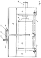
- FIG. 1 shows a filter press in a longitudinal side view with a support structure 10, which sits on side stands 12, 14. That depends on the stands 12, 14 several filter plates and between the top plate 16 and the end plate 18th tightened filter plate package 20.
- the filter plates of the piston-cylinder unit 26 are an exemplary embodiment tied together. The cleaning of the filter cloths takes place in certain cycles or at Need instead.
- a cleaning device 28 which cleans dry or wet can be used, which rests on the upper flange of one of the supports 30, 32 and which the lower tie rod 22 is guided and supported.
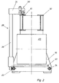
- the washing device shown for example in Figure 2 has an upper cross member 34 on which the drive 36 sits on the right and the vertical guide 38 for the left Wash bar 40 is attached.
- the wash bar rises and falls in each open one Filter chamber, where water remains under high pressure from the nozzles of the wash bar of the filter cake from the filter cloths.
- the one intended for transporting the cleaning device along the carrier 30 Drive 36 transmits its drive power via a gear to the sprocket or Toothed washer 42.
- This toothed washer 42 which is directly coupled to the drive, in turn drives another toothed pulley 44, a toothed belt 46 being used as the drive means is coming.
- the infinite toothed belt wraps around the two toothed pulleys 42, 44, the Engage teeth 48 of toothed pulleys 42, 44 between teeth 50 of toothed belt 46.
- the stability of the toothed belt 46 is increased by embedded reinforcing wires 52.
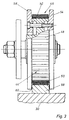
- the entire drive unit which in this case moves the cleaning device 28, is held at the end of the cross member 34 in a carriage 53.
- the tooth lock washers are on attached to this sled by bolts and nuts.
- the toothed disc 44 is on on both long sides with discs 54, 56, which are also referred to as flanged wheels become. These disks 54, 56 protrude beyond the diameter of the toothed disks 42, 44 addition, so that there is a guide bar 58 between them in its lower region take up.
- the guide bar itself centers the toothed washer by contact of the disc flanks 60 on the long sides of the guide bar 58.
- toothed belt itself and the entire drive unit have its own side guide.
- tooth lock washers 42, 44 laterally with the disks 54, 56, also called flanged disks, and additionally spanned by a U-shaped bracket 62. Since the entire drive from Centering and guiding the bracket can be done separately Design the timing belt design more precisely or the guidance of the entire slide run more robust.
- the carrier (s) can also have U-shaped profiles open at the top carry. These profiles can, if they are made of metal, with a be elastic pad to avoid increased noise.
- FIG. 5 shows a further variant of the invention, in which the drive on one first sled sits.
- the gear connected to the drive wraps around you Timing belt in contact with the pulleys of a second slide. Due to the Belt length is a tension pulley 66 between the two pulleys of the second Arranged sled. The number of elements wrapped in the toothed belt increases the area for transmission of drive power (traction).
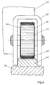
- FIG. 6 shows an embodiment of the toothed disks 42, 44 which consists of a Flange wheel with guidance on both sides.
- a larger dimensioned guide pulley 70 is provided, with its Is guided on the inside of the carrier 30 or on a support 72 on the carrier.
- a plastic is used for the support.
- the plastic is connected with the metallic carrier through an adhesive.
- the plastic pad is in the present case is rectangular. It surrounds the wearer on its top and lateral contact surface.
- FIG. 7 shows a special guidance of the toothed belt 46 on the toothed wheels 42, 44
- gear wheels have a groove 74 in their peripheral surface.
- the Web 76 of the toothed belt 46 guided.
- the toothed belt 46 engages.
- the toothed belt 46 has a profile on its tread 78 80.
Landscapes
- Chemical & Material Sciences (AREA)
- Chemical Kinetics & Catalysis (AREA)
- Devices For Conveying Motion By Means Of Endless Flexible Members (AREA)
- Filtration Of Liquid (AREA)
- Feeding Of Articles By Means Other Than Belts Or Rollers (AREA)
- Vehicle Body Suspensions (AREA)
- Filtering Of Dispersed Particles In Gases (AREA)
- Supporting Of Heads In Record-Carrier Devices (AREA)
Abstract
Description
Die Erfindung betrifft einen Antrieb für die Reingigungs- und/oder Filterplattenverschiebevorrichtung an Filterpressen entsprechend dem Oberbegriff des Patentanspruchs 1.The invention relates to a drive for the cleaning and / or filter plate displacement device on filter presses according to the preamble of claim 1.
Aus der DE 30 43 821 C2 geht eine Filterpresse mit einem Reinigungswagen hervor. Die
einzige Figur zeigt dabei die Filterpresse mit einem Kopfträger an dem die Filterplatten
hängen. Die dazu verwendeten Filterplattenaufhängungen sind mit der Filterplatte
verschraubt und am horizontalen Träger mittels Rollen aufgehängt. Der Reinigungswagen
der auf dem Kopfträger vor- und rückwärts beweglich ist, trägt sowohl die
Wascheinrichtung wie auch eine Einheit zum Verschieben der Filterplatten.
Die DE 18 10 112 C2 zeigt eine Filterpresse mit auf Seitenholmen aufliegenden Filterplatten. Die mit Rollen versehene Verschiebevorrichtung dagegen fährt auf Führungsstangen oberhalb des Filterplattenpakets. Zum Transport der Filterplatten können verschiedenartig gestaltete Ausführungen der Transportelemente die Filterplatten jeweils an ihrer oberen Seite greifen. Der Schlitten der Verschiebevorrichtung sitzt anhand seiner Rollen direkt auf Führungsstangen auf.DE 18 10 112 C2 shows a filter press with resting on side rails Filter plates. The shifting device provided with rollers, on the other hand, opens Guide rods above the filter plate package. Can be used to transport the filter plates different designs of the transport elements, the filter plates each grab on their top side. The carriage of the displacement device sits based on it Roll up directly on guide rods.
Die DE 28 23 501 C1 zeigt in Figur 4 die Transporteinrichtung für die Waschvorrichtung.
Der dargestellte Wagen läuft auf einem über den Filterplatten befindlichen Träger auf
Rollen. Auf dem Träger kann, wie beispielsweise ausgeführt wird, auch eine Kette oder
eine Zahnstange o.ä. angeordnet sein, in die ein von einem Motor direkt angetriebenes
Antriebselement eingreift.
Eine Filterpresse mit zwei unterschiedlichen Antriebssystemen für die Bewegung der Verschiebevorrrichtung auf Horizontalträgern und für die eigenständige Vereinzelung der Filterplatten zeigen die Figuren 1 und 6 der DE 39 24 938 C1. Die Längsbewegung des Schlittens der Verschiebevorrichtung geschieht über einen Antrieb, der auf Antriebsrollen einwirkt. Die Rollen selbst liegen auf horizontalen Schienen auf. Zur Verschiebung der Filterplatten werden eine mit Klinken versehene Kette und ein Sternrad eingesetzt. Die Kette läuft über zwei Zahnräder um, dabei greifen die Klinken an der Kette jeweils in die von einem Sternrad freigegebene Filterplatte, wogegen die nächste durch das Sternrad zurückgehalten wird. A filter press with two different drive systems for moving the Sliding device on horizontal beams and for the independent separation of the Filter plates show Figures 1 and 6 of DE 39 24 938 C1. The longitudinal movement of the The slide device is slid via a drive on drive rollers acts. The rollers themselves rest on horizontal rails. To postpone the A plate with a pawl and a star wheel are used for filter plates. The The chain runs over two gears, and the pawls on the chain each engage in the filter plate released by a star wheel, while the next through the star wheel is held back.
Aufgabe der vorliegenden Erfindung ist es, einen Antrieb für Reinigungs- und/oder Filterplattenverschiebevorrichtungen so zu gestalten, daß eine verbesserte Übertragung der Antriebsleistung bei hoher Laufruhe und geringer Verschmutzung erreicht wird.The object of the present invention is to provide a drive for cleaning and / or Filter plate shifting devices so that an improved transmission of the Drive power is achieved with smooth running and low pollution.
Diese Aufgabe ist erfindungsgemäß durch die kennzeichnenden Merkmale des Anspruch 1 gelöst.This object is achieved by the characterizing features of claim 1 solved.
Durch die erfindungsgemäßen Maßnahmen vergrößert sich die Fläche zur Übertragung der Traktion über die sich die Antriebsleistung vom Antrieb auf die Führungen übertragen läßt.The measures according to the invention increase the area for transmitting the Traction through which the drive power can be transferred from the drive to the guides.
Sowohl der Antrieb wie auch das Übertragungsmittel - im speziellen Erfindungsfall der Zahnriemen - unterliegen hierbei einer wesentlich schonenderen Betriebsweise als beim Stand der Technik.Both the drive and the transmission medium - in the special case of invention Timing belts - are subject to a much gentler mode of operation than with State of the art.
In der Weiterbildung der Erfindung nach den Unteransprüchen kommen Zahnscheiben in Verbindung mit einem Zahnriemen zum Einsatz, deren Zähne ineinandergreifen. Aufgrund der Verwendung eines unendlichen Zahnriemens sinkt der Verschmutzungsgrad, da die Zahnscheiben nahezu vollständig abgedeckt sind.In the development of the invention according to the dependent claims, toothed pulleys come in Connection with a toothed belt to be used, the teeth of which mesh. Because of the use of an infinite toothed belt reduces the degree of contamination because the Toothed lock washers are almost completely covered.
Die Verwendung einer schienen- oder leistenartigen Auflage auf dem Träger gibt die Möglichkeit, daß der Zahnriemen auf einem nichtmetallischen Trägermaterial abrollt, wobei die Haftung und auch die Laufruhe wesentlich beeinflußt werden können.The use of a rail or strip-like support on the carrier gives the Possibility that the toothed belt rolls on a non-metallic carrier material, wherein liability and smoothness can be significantly influenced.
Obwohl die Darstellung des Ausführungsbeispiels gem. Figur 1 einen Transportschlitten für eine Waschvorrichtung zeigt, läßt sich der erfindungsgemäße Antrieb auch bei Filterplattentransportvorrichtungen oder Kombinationen aus beidem verwenden.Although the representation of the embodiment according to 1 shows a transport carriage for shows a washing device, the drive according to the invention can also be used Use filter plate transport devices or combinations of both.
In einer erfindungsgemäßen Weiterbildung weisen die Zahnscheiben eine Führung für den Zahnriemen auf. Die Führung besteht aus einer Nut in der Umfangsfläche der Zahnscheiben in die der Steg des Zahnriemens eingreift.In a further development according to the invention, the toothed disks have a guide for the Timing belt. The guide consists of a groove in the peripheral surface of the toothed lock washer in which the web of the toothed belt engages.
Nachfolgend wird ein Ausführungsbeispiel der Erfindung anhand der Zeichnungen näher erläutert:An exemplary embodiment of the invention is described in more detail below with reference to the drawings explains:
Es zeigen:
- Figur 1
- Eine schematische Darstellung einer Filterpresse mit Waschvorrichtung in der Seitenansicht
- Figur 2
- Vertikaler Schnitt der Filterpresse mit Waschvorrichtung
- Figur 3
- Zahnriemenführung mit Aufbruch
- Figur 4
- Zahnriemenführung mit Bügel
- Figur 5
- Seitenansicht des Antriebs
- Figur 6
- Zahnriemenführung auf Kunststoffprofil
- Figur 7
- Zahnscheibe mit Führungsnut
- Figure 1
- A schematic representation of a filter press with washing device in a side view
- Figure 2
- Vertical section of the filter press with washing device
- Figure 3
- Timing belt guide with opening
- Figure 4
- Timing belt guide with bracket
- Figure 5
- Side view of the drive
- Figure 6
- Toothed belt guide on plastic profile
- Figure 7
- Toothed lock washer with guide groove
Die Figur 1 zeigt eine Filterpresse in Längsseitenansicht mit einer Trägerkonstruktion 10,
die auf seitlichen Ständern 12, 14 aufsitzt. Zwischen den Ständern 12, 14 hängt das aus
mehreren Filterplatten bestehende und zwischen der Kopfplatte 16 und der Endplatte 18
zusammengespannte Filterplattenpaket 20. Zur Fixierung und Stabilisierung des gesamten
Filterpressenrahmens verbinden zwei Zugstangen 22, 24 die Ständer 12, 14. Im
Ausführungsbeispiel sind die Filterplatten von der Kolbenzylindereinheit 26
zusammengespannt. Die Reinigung der Filtertücher findet in bestimmten Zyklen oder bei
Bedarf statt. Dazu kommt eine Reinigungsvorrichtung 28 die trocken oder naß reinigen
kann zum Einsatz, die auf dem oberen Flansch einer der Träger 30, 32 aufliegt und die an
der unteren Zugstange 22 geführt und gestützt ist.FIG. 1 shows a filter press in a longitudinal side view with a
Die in Figur 2 beispielsweise dargestellte Waschvorrichtung weist einen oberen Querträger
34 auf, an dem rechts der Antrieb 36 sitzt und links die senkrechte Führung 38 für den
Waschbalken 40 befestigt ist. Der Waschbalken hebt und senkt sich in jeder geöffneten
Filterkammer, wobei Wasser unter hohem Druck aus den Düsen des Waschbalkens Reste
des Filterkuchens von den Filtertüchern abspritzt.The washing device shown for example in Figure 2 has an
Der für den Transport der Reinigungsvorrichtung entlang dem Träger 30 vorgesehene
Antrieb 36 überträgt seine Antriebsleistung über ein Getriebe auf die Zahnrolle bzw.
Zahnscheibe 42. Diese direkt mit dem Antrieb gekoppelte Zahnscheibe 42 wiederum treibt
eine weitere Zahnscheibe 44 an, wobei als Antriebsmittel ein Zahnriemen 46 zum Einsatz
kommt. Der unendliche Zahnriemen umschlingt die beiden Zahnscheiben 42, 44, wobei die
Zähne 48 der Zahnscheiben 42, 44 zwischen die Zähne 50 des Zahnriemens 46 eingreifen.
Die Stabilität des Zahnriemens 46 wird erhöht durch eingelagerte Armierungsdrähte 52. The one intended for transporting the cleaning device along the
Die gesamte, in diesem Fall die Reinigungsvorrichtung 28 bewegende Antriebseinheit, ist
am Ende des Querträgers 34 in einem Schlitten 53 gehalten. Die Zahnscheiben sind an
diesem Schlitten durch Bolzen und Muttern befestigt. In Figur 3 ist die Zahnscheibe 44 an
beiden Längsseiten mit Scheiben 54, 56 belegt, die auch als Spurkranzrollen bezeichnet
werden. Diese Scheiben 54, 56 ragen über den Durchmesser der Zahnscheiben 42, 44
hinaus, so daß sie in ihrem unteren Bereich eine Führungsleiste 58 zwischen sich
aufnehmen. Die Führungsleiste selbst zentriert demnach die Zahnscheibe durch Anliegen
der Scheibenflanken 60 an den Längsseiten der Führungsleiste 58. Aufgrund der
Vervielfachung der Traktionspunkte, herbeigeführt über die Führung des Zahnriemens über
zwei Zahnscheiben 42, 44 auf der Führungsleiste 58, erhöht sich der Wirkungsgrad des
Antriebs erheblich. Ein weiterer Vorteil liegt in der Verwendung des unendlichen
Zahnriemens 46, der beide Zahnscheiben 42, 44 umschlingt und damit die ansonsten
schnell verschmutzenden Verzahnungen bei bloßer Ritzelverwendung vermeidet.The entire drive unit, which in this case moves the
Nachdem die Zahnscheiben 42, 44 direkt auf dem mehr oder weniger elastischen
Zahnriemen aufliegen bzw. abrollen, ist damit auch eine geräuscharme Betriebsweise
verbunden.After the
Aus Figur 4 geht eine Ausführungsform hervor, bei der der Zahnriemen selbst und die
gesamte Antriebseinheit eine eigene Seitenführung aufweisen. Dazu sind die Zahnscheiben
42, 44 seitlich mit den Scheiben 54, 56, auch Bordscheiben genannt, belegt und
zusätzlich von einem U-förmigen Bügel 62 überspannt. Da der gesamte Antrieb hierbei vom
Bügel zentriert und geführt wird, läßt sich die getrennt bewerkstelligte
Zahnriemenausführung exakter auslegen bzw. die Führung des gesamten Schlittens
robuster ausführen.4 shows an embodiment in which the toothed belt itself and the
entire drive unit have its own side guide. In addition there are the
Anstatt des Bügels kann/können der/die Träger auch U-förmige nach oben offene Profile tragen. Diese Profile können wiederum, sofern sie aus Metall bestehen, mit einer elastischen Auflage versehen sein, um erhöhte Geräuscherzeugung zu vermeiden.Instead of the bracket, the carrier (s) can also have U-shaped profiles open at the top carry. These profiles can, if they are made of metal, with a be elastic pad to avoid increased noise.
Aus Figur 5 geht eine weitere Variante der Erfindung hervor, bei der der Antrieb an einem
ersten Schlitten sitzt. Das mit dem Antrieb verbundene Zahnrad umschlingt einen
Zahnriemen, der mit den Scheiben eines zweiten Schlittens in Kontakt steht. Aufgrund der
Länge des Riemens ist eine Spannrolle 66 zwischen den beiden Scheiben des zweiten
Schlittens angeordnet. Die Anzahl der vom Zahnriemen umschlungenen Elemente
vergrößert die Fläche zur Übertragung der Antriebsleistung (Traktion). FIG. 5 shows a further variant of the invention, in which the drive on one
first sled sits. The gear connected to the drive wraps around you
Timing belt in contact with the pulleys of a second slide. Due to the
Belt length is a
Aus Figur 6 geht eine Ausführungsform der Zahnscheiben 42, 44 hervor, die aus einer
Spurkranzrolle mit beidseitiger Führung besteht. Zusätzlich dazu ist an einer Seite des
Zahnriemens 46 eine größer dimensionierte Führungsscheibe 70 vorgesehen, die mit ihrer
Innenseite am Träger 30 oder an einer Auflage 72 auf dem Träger geführt ist. Als Material
für die Auflage kommt hierbei ein Kunststoff zum Einsatz. Verbunden wird der Kunststoff
mit dem metallischen Träger durch einen Klebstoff. Die Auflage aus Kunststoff ist im
vorliegenden Fall rechtwinklig geformt. Sie umgibt den Träger auf seiner oberen und
seitlichen Anlagefläche.FIG. 6 shows an embodiment of the
Figur 7 zeigt eine besondere Führung des Zahnriemens 46 an den Zahnrädern 42, 44. Die
Zahnräder haben in diesem Fall eine Nut 74 in deren Umfangsfläche. In dieser Nut wird der
Steg 76 des Zahnriemens 46 geführt. In die beidseitige Verzahnung neben der Nut 74
greift der Zahnriemen 46 ein. Der Zahnriemen 46 hat auf seiner Lauffläche 78 ein Profil
80.FIG. 7 shows a special guidance of the
Claims (9)
dadurch gekennzeichnet, daß der Antrieb (36) mit einer ersten Scheibe (42) und über einen unendlichen Riemen (46) mit mindestens einer weiteren Scheibe (44) so verbunden ist, daß der Riemen (46) direkt auf einem Träger (30, 32) oder einer mit dem Träger verbundenen Auflage (58, 72) abrollt.Drive for a cleaning and / or filter plate shifting device mounted on a horizontal support (30, 32) on filter presses with filter plates suspended on horizontally arranged supports (30, 32), which lie tightly against one another during the filtering process as a filter plate package (20) and separated after the filtering process will,
characterized in that the drive (36) is connected to a first pulley (42) and via an infinite belt (46) to at least one further pulley (44) in such a way that the belt (46) directly on a carrier (30, 32 ) or a support (58, 72) connected to the carrier.
dadurch gekennzeichnet, daß der unendliche Riemen (46) ein Zahnriemen ist.Drive according to claim 1,
characterized in that the infinite belt (46) is a toothed belt.
dadurch gekennzeichnet, daß die Scheiben (42, 44) mit einer Außenverzahnung (48) versehen sind, in die die Zähne (50) des Zahnriemens (46) eingreifen und der Zahnriemen (46) von ein- oder beidseitig über diese Zahnscheiben (42,44) überstehenden Scheiben (54, 56) begrenzt ist.Drive according to claim 1,
characterized in that the pulleys (42, 44) are provided with external toothing (48) into which the teeth (50) of the toothed belt (46) engage and the toothed belt (46) from one or both sides via these toothed pulleys (42, 44) projecting washers (54, 56) is limited.
dadurch gekennzeichnet, daß der Zahnriemen (46) auf einer auf den Träger (30, 32) aufgesetzten Führungsleiste (58) aufliegt, der mindestens einseitig eine als Anschlag dienende Scheibe (54) zugeordnet ist.Drive according to claim 1 or 2,
characterized in that the toothed belt (46) rests on a guide bar (58) which is placed on the carrier (30, 32) and to which a pulley (54) serving as a stop is assigned at least on one side.
dadurch gekennzeichnet, daß die Zahnscheiben (42, 44) ein U-förmiger Bügel (62) umgreift, dessen Schenkelenden beidseitig an den Längsseiten der Führungsleiste (58) geführt sind.Drive according to one of claims 1-3,
characterized in that the toothed disks (42, 44) surround a U-shaped bracket (62), the leg ends of which are guided on both sides on the longitudinal sides of the guide strip (58).
dadurch gekennzeichnet, daß die Führungsleiste (58) aus einem nichtmetallischen Material besteht. Drive according to claim 4,
characterized in that the guide bar (58) is made of a non-metallic material.
dadurch gekennzeichnet, daß die Scheiben (42, 44) auf ihrer Umfangsfläche eine Führung für den Riemen (46) aufweisen.Drive according to one of claims 1-6,
characterized in that the pulleys (42, 44) have a guide for the belt (46) on their peripheral surface.
dadurch gekennzeichnet, daß die Scheiben (42, 44) eine zentrische Nut (74) aufweisen, in der der Steg (76) des Zahnriemens (46) geführt ist.Drive according to claim 7,
characterized in that the disks (42, 44) have a central groove (74) in which the web (76) of the toothed belt (46) is guided.
dadurch gekennzeichnet, daß die Scheiben (42, 44) beidseitig von der Nut eine Verzahnung aufweisen.Drive according to claim 8,
characterized in that the washers (42, 44) have teeth on both sides of the groove.
Applications Claiming Priority (2)
| Application Number | Priority Date | Filing Date | Title |
|---|---|---|---|
| DE19733486A DE19733486C1 (en) | 1997-08-01 | 1997-08-01 | Drive for filter press cleaning and/or filter plate displacement device |
| DE19733486 | 1997-08-01 |
Publications (3)
| Publication Number | Publication Date |
|---|---|
| EP0894518A2 true EP0894518A2 (en) | 1999-02-03 |
| EP0894518A3 EP0894518A3 (en) | 1999-12-15 |
| EP0894518B1 EP0894518B1 (en) | 2004-03-24 |
Family
ID=7837814
Family Applications (1)
| Application Number | Title | Priority Date | Filing Date |
|---|---|---|---|
| EP98113291A Expired - Lifetime EP0894518B1 (en) | 1997-08-01 | 1998-07-16 | Driving means for cleaning and shifting devices in filter presses |
Country Status (6)
| Country | Link |
|---|---|
| EP (1) | EP0894518B1 (en) |
| AT (1) | ATE262367T1 (en) |
| CZ (1) | CZ287819B6 (en) |
| DE (2) | DE19733486C1 (en) |
| ES (1) | ES2213858T3 (en) |
| SK (1) | SK282941B6 (en) |
Citations (3)
| Publication number | Priority date | Publication date | Assignee | Title |
|---|---|---|---|---|
| FR2287258A1 (en) * | 1974-10-08 | 1976-05-07 | Von Roll Ag | Filter cake scrape-off device - for plate filter presses |
| EP0247445A1 (en) * | 1986-05-24 | 1987-12-02 | Karl Häcker | Washing apparatus for filter cloths |
| WO1988003832A1 (en) * | 1986-11-28 | 1988-06-02 | Envirotech Corporation | Apparatus for shifting filter plates in a filter press |
Family Cites Families (3)
| Publication number | Priority date | Publication date | Assignee | Title |
|---|---|---|---|---|
| DE2823501C2 (en) * | 1978-05-30 | 1985-04-18 | Eberhard Hoesch & Söhne GmbH & Co, 5160 Düren | Plate filter press with control device for moving the plate shifting device and any filter cloth washing car |
| DE3043821C2 (en) * | 1980-11-20 | 1983-10-20 | Passavant-Werke AG & Co KG, 6209 Aarbergen | Plate filter press with a cleaning trolley |
| DE3924938C1 (en) * | 1989-07-27 | 1991-01-03 | Erich Netzsch Gmbh & Co Holding Kg, 8672 Selb, De | Filter paper-removing device in filter press - comprises conveyance in which supports travel longitudinally, drive mechanism, restraining means, positioning means and stopping means |
-
1997
- 1997-08-01 DE DE19733486A patent/DE19733486C1/en not_active Expired - Fee Related
-
1998
- 1998-07-15 CZ CZ19982230A patent/CZ287819B6/en not_active IP Right Cessation
- 1998-07-16 ES ES98113291T patent/ES2213858T3/en not_active Expired - Lifetime
- 1998-07-16 AT AT98113291T patent/ATE262367T1/en not_active IP Right Cessation
- 1998-07-16 EP EP98113291A patent/EP0894518B1/en not_active Expired - Lifetime
- 1998-07-16 DE DE59811040T patent/DE59811040D1/en not_active Expired - Fee Related
- 1998-07-17 SK SK982-98A patent/SK282941B6/en unknown
Patent Citations (3)
| Publication number | Priority date | Publication date | Assignee | Title |
|---|---|---|---|---|
| FR2287258A1 (en) * | 1974-10-08 | 1976-05-07 | Von Roll Ag | Filter cake scrape-off device - for plate filter presses |
| EP0247445A1 (en) * | 1986-05-24 | 1987-12-02 | Karl Häcker | Washing apparatus for filter cloths |
| WO1988003832A1 (en) * | 1986-11-28 | 1988-06-02 | Envirotech Corporation | Apparatus for shifting filter plates in a filter press |
Also Published As
| Publication number | Publication date |
|---|---|
| DE19733486C1 (en) | 1998-09-24 |
| EP0894518A3 (en) | 1999-12-15 |
| ATE262367T1 (en) | 2004-04-15 |
| ES2213858T3 (en) | 2004-09-01 |
| CZ223098A3 (en) | 1999-03-17 |
| SK98298A3 (en) | 1999-02-11 |
| DE59811040D1 (en) | 2004-04-29 |
| CZ287819B6 (en) | 2001-02-14 |
| EP0894518B1 (en) | 2004-03-24 |
| SK282941B6 (en) | 2003-01-09 |
Similar Documents
| Publication | Publication Date | Title |
|---|---|---|
| DE1925284B2 (en) | CLUTCH CHAIN FOR TENSION CLUTCHES IN TENSION FRAMES | |
| DE69010515T2 (en) | Conveyor belt with self-propelled load carriers. | |
| CH630267A5 (en) | PROCESSING DEVICE FOR THE FILTER PLATES OF A FILTER PRESS, BASED ON TWO HORIZONTAL GUIDE CARRIERS. | |
| EP0718020A1 (en) | Filter press for filtering suspensions | |
| EP0541850B1 (en) | Curvilinear plate conveyor | |
| DE2050503C3 (en) | Belt filter for liquids | |
| DE2613149B2 (en) | Device for cleaning conveyor belts | |
| DE4243038A1 (en) | Horizontal band filter | |
| EP0894518B1 (en) | Driving means for cleaning and shifting devices in filter presses | |
| DE3439647C2 (en) | Drive trolley of an electric overhead conveyor with automatic gearbox | |
| DE3413528A1 (en) | Device for conveying freight on lorries | |
| DE102008055482B4 (en) | Method and device for the continuous application of edge profile strips on a conveyor belt of a conveyor system | |
| DE1965312C3 (en) | Drive for conveyor chains with load carriers | |
| DE3634135A1 (en) | DEVICE FOR LOADING AND UNLOADING LOADED GOODS | |
| WO2004024528A1 (en) | Self-propelling cable car and drive for a cable | |
| DE2853952A1 (en) | PLATE FILTER PRESS WITH VERTICALLY ALIGNED FILTER ELEMENTS AND FILTER CLOTH TRANSPORT | |
| DE4121516A1 (en) | CONVEYING SYSTEM WITH A SUPPORT RAIL WITH RUNNINGS FOR DRIVED VEHICLE SUPPORT WHEELS | |
| DE3643662C1 (en) | Lifting and lowering station for a rail piece | |
| DE3222989A1 (en) | PLATE FILTER | |
| DE3307488C2 (en) | Drive device for a monorail overhead conveyor in conveyor systems | |
| DE3502227C2 (en) | ||
| DE2021258A1 (en) | Apparatus for drying clothes | |
| DE3131594C2 (en) | Kluppenkettenbahn | |
| DE1217857B (en) | Steep conveyor | |
| DE903188C (en) | Device for driving conveyor belts or conveyor belt sections |
Legal Events
| Date | Code | Title | Description |
|---|---|---|---|
| PUAI | Public reference made under article 153(3) epc to a published international application that has entered the european phase |
Free format text: ORIGINAL CODE: 0009012 |
|
| AK | Designated contracting states |
Kind code of ref document: A2 Designated state(s): AT DE ES FR GB IT |
|
| AX | Request for extension of the european patent |
Free format text: AL;LT;LV;MK;RO;SI |
|
| PUAL | Search report despatched |
Free format text: ORIGINAL CODE: 0009013 |
|
| AK | Designated contracting states |
Kind code of ref document: A3 Designated state(s): AT BE CH CY DE DK ES FI FR GB GR IE IT LI LU MC NL PT SE |
|
| AX | Request for extension of the european patent |
Free format text: AL;LT;LV;MK;RO;SI |
|
| 17P | Request for examination filed |
Effective date: 19991208 |
|
| AKX | Designation fees paid |
Free format text: AT DE ES FR GB IT |
|
| 17Q | First examination report despatched |
Effective date: 20020927 |
|
| GRAP | Despatch of communication of intention to grant a patent |
Free format text: ORIGINAL CODE: EPIDOSNIGR1 |
|
| GRAS | Grant fee paid |
Free format text: ORIGINAL CODE: EPIDOSNIGR3 |
|
| GRAA | (expected) grant |
Free format text: ORIGINAL CODE: 0009210 |
|
| AK | Designated contracting states |
Kind code of ref document: B1 Designated state(s): AT DE ES FR GB IT |
|
| REG | Reference to a national code |
Ref country code: GB Ref legal event code: FG4D Free format text: NOT ENGLISH |
|
| REF | Corresponds to: |
Ref document number: 59811040 Country of ref document: DE Date of ref document: 20040429 Kind code of ref document: P |
|
| GBT | Gb: translation of ep patent filed (gb section 77(6)(a)/1977) |
Effective date: 20040423 |
|
| PGFP | Annual fee paid to national office [announced via postgrant information from national office to epo] |
Ref country code: GB Payment date: 20040621 Year of fee payment: 7 |
|
| PGFP | Annual fee paid to national office [announced via postgrant information from national office to epo] |
Ref country code: ES Payment date: 20040707 Year of fee payment: 7 |
|
| PGFP | Annual fee paid to national office [announced via postgrant information from national office to epo] |
Ref country code: FR Payment date: 20040721 Year of fee payment: 7 Ref country code: AT Payment date: 20040721 Year of fee payment: 7 |
|
| PGFP | Annual fee paid to national office [announced via postgrant information from national office to epo] |
Ref country code: DE Payment date: 20040809 Year of fee payment: 7 |
|
| REG | Reference to a national code |
Ref country code: ES Ref legal event code: FG2A Ref document number: 2213858 Country of ref document: ES Kind code of ref document: T3 |
|
| ET | Fr: translation filed | ||
| PLBE | No opposition filed within time limit |
Free format text: ORIGINAL CODE: 0009261 |
|
| STAA | Information on the status of an ep patent application or granted ep patent |
Free format text: STATUS: NO OPPOSITION FILED WITHIN TIME LIMIT |
|
| 26N | No opposition filed |
Effective date: 20041228 |
|
| PG25 | Lapsed in a contracting state [announced via postgrant information from national office to epo] |
Ref country code: IT Free format text: LAPSE BECAUSE OF NON-PAYMENT OF DUE FEES;WARNING: LAPSES OF ITALIAN PATENTS WITH EFFECTIVE DATE BEFORE 2007 MAY HAVE OCCURRED AT ANY TIME BEFORE 2007. THE CORRECT EFFECTIVE DATE MAY BE DIFFERENT FROM THE ONE RECORDED. Effective date: 20050716 Ref country code: GB Free format text: LAPSE BECAUSE OF NON-PAYMENT OF DUE FEES Effective date: 20050716 Ref country code: AT Free format text: LAPSE BECAUSE OF NON-PAYMENT OF DUE FEES Effective date: 20050716 |
|
| PG25 | Lapsed in a contracting state [announced via postgrant information from national office to epo] |
Ref country code: ES Free format text: LAPSE BECAUSE OF NON-PAYMENT OF DUE FEES Effective date: 20050718 |
|
| PG25 | Lapsed in a contracting state [announced via postgrant information from national office to epo] |
Ref country code: DE Free format text: LAPSE BECAUSE OF NON-PAYMENT OF DUE FEES Effective date: 20060201 |
|
| GBPC | Gb: european patent ceased through non-payment of renewal fee |
Effective date: 20050716 |
|
| PG25 | Lapsed in a contracting state [announced via postgrant information from national office to epo] |
Ref country code: FR Free format text: LAPSE BECAUSE OF NON-PAYMENT OF DUE FEES Effective date: 20060331 |
|
| REG | Reference to a national code |
Ref country code: FR Ref legal event code: ST Effective date: 20060331 |
|
| REG | Reference to a national code |
Ref country code: ES Ref legal event code: FD2A Effective date: 20050718 |