EP0894450A2 - Cleaning comb with teeth having a predetermined roughness on their outer surface and method of manufacturing a cleaning comb of high mechanical strength - Google Patents
Cleaning comb with teeth having a predetermined roughness on their outer surface and method of manufacturing a cleaning comb of high mechanical strength Download PDFInfo
- Publication number
- EP0894450A2 EP0894450A2 EP98114393A EP98114393A EP0894450A2 EP 0894450 A2 EP0894450 A2 EP 0894450A2 EP 98114393 A EP98114393 A EP 98114393A EP 98114393 A EP98114393 A EP 98114393A EP 0894450 A2 EP0894450 A2 EP 0894450A2
- Authority
- EP
- European Patent Office
- Prior art keywords
- teeth
- tooth
- shell
- comb
- handle
- Prior art date
- Legal status (The legal status is an assumption and is not a legal conclusion. Google has not performed a legal analysis and makes no representation as to the accuracy of the status listed.)
- Granted
Links
Images
Classifications
-
- A—HUMAN NECESSITIES
- A45—HAND OR TRAVELLING ARTICLES
- A45D—HAIRDRESSING OR SHAVING EQUIPMENT; EQUIPMENT FOR COSMETICS OR COSMETIC TREATMENTS, e.g. FOR MANICURING OR PEDICURING
- A45D24/00—Hair combs for care of the hair; Accessories therefor
- A45D24/30—Combs specially adapted for removing dirt or grease
-
- A—HUMAN NECESSITIES
- A61—MEDICAL OR VETERINARY SCIENCE; HYGIENE
- A61B—DIAGNOSIS; SURGERY; IDENTIFICATION
- A61B17/00—Surgical instruments, devices or methods, e.g. tourniquets
- A61B17/50—Instruments, other than pincettes or toothpicks, for removing foreign bodies from the human body
- A61B2017/505—Parasite, e.g. tick, removers
Definitions
- the present invention relates to a cleaning comb with teeth, which in have a roughness on their peripheral surface, and a method for Production of a cleaning comb with high mechanical strength.
- a comb for cleaning the Hair described by lice and nits has teeth with one triangular cross-section.
- the diameter of the teeth decreases from that Fastening ends towards the application ends such that the distance between adjacent teeth near the application ends is larger than in close to the handle.
- the teeth are arranged so that their longitudinal axes are parallel and that they are in two parallel planes, with adjacent teeth alternately belong to one of the two levels. With this arrangement, a Scissors effect achieved to remove the lice and nits from the hair.
- comb has some disadvantages.
- the teeth have a relatively short length which is not guaranteed in every hair type with the tooth tips up to the scalp to get.
- the distances between the tips of the application ends of the teeth are quite large, so the effectiveness against the lice and especially against the nits is significantly reduced.
- the teeth show through their Triangular shape has sharp edges, and therefore have a tendency to absolutely undesirable effect of hurting the surface of the hair.
- the comb includes a variety of teeth made of metal fastened in a handle, at a distance between the teeth of approx. 100 ⁇ m to 120 ⁇ m. Every tooth is close to its End of attachment provided with an elongated channel that each elongated connecting element in the handle corresponds complementarily, whereby it is ensured that the teeth both during the manufacture of the comb and also be kept in parallel during its use.
- the teeth have one Usable length, that is, a part that protrudes outwards from the handle and to Combing the hair can be used of 9 mm or less, and the tips the teeth are hook-shaped to better lice and nits from the To be able to remove hair.
- the short useful length of the teeth is not sufficient to reach the surface of the scalp with the comb.
- this comb has not the desired one Effectiveness for the removal of particles adhering to the hair, such as Example the nits are because the distance between the individual teeth is much too large is and the surface of the teeth is smooth, whereby the majority of nits are not at Comb sticks.
- An object of the present invention is to provide a comb to provide with significantly improved properties for cleaning any Hair types or the like, of firmly adhering particles and in particular of Objects such as nits, which are generally very firmly attached to the hair, without damaging the hair at the same time.
- Another object of the present invention is various Methods to produce cleaning combs that, despite the fact that they have teeth with a relatively large usable length, a high mechanical one Have resistance to deformation.
- Another object of the present invention is teeth for combs to produce, which have a peripheral surface with a roughness, the in particular special properties for the removal of firmly on the hair adhering particles.
- the cleaning comb comprises teeth, which have a roughness on their peripheral surface, which are parallel in one Are arranged level and a distance between them of less than 100 microns exhibit to all foreign items and smaller ones in an efficient manner Remove particles adhering to the hair.
- the teeth have a usable length, that means one out of the handle protruding part, of at least 35 mm to be effective because of shorter teeth cause that the cleaning of hair is far too labor-intensive, especially at thick and abundant hair.
- the teeth have a cross-section without sharp edges, so that is Cross-section circular or oval, and preferably the teeth must be one in have an essentially cylindrical shape so that they have to be combed and cleaned Do not damage hair.
- the teeth are made of one material with a mechanical one Strength equal to or greater than that of steel, and they are preferred from stainless steel manufactured with a diameter of at least 1 mm to the Comb, despite the relatively large usable length, high mechanical strength to lend; with the comb when cleaning the hair of the nits resistance is overcome.
- the teeth of the comb according to the invention have a major novelty a peripheral surface with a fine roughness that has the effect of foreign To remove particles that adhere to the hair, with an essential higher efficiency than that known from the teeth from the prior art is; with the cleaning comb of the present invention, for example, between 30 and 50% more nits are removed than with the prior art Technology known combs is possible.
- any roughness can be used to make the To improve the cleaning effect of the comb are considered preferred roughness with the best cleaning results and / or the lowest manufacturing costs, used those made of fine, the nits, not the hair damaging grooves.
- the grooves can be provided as helical groove with a not too large thread, or as a parallel annular annular grooves with a precisely defined, not too large distance among themselves.
- the teeth on a handle made of aseptic material are preferred attached, such as stainless steel, which is boiled in hot water every day can become without deforming.
- the method includes Manufacturing the cleaning comb involves the steps of a variety of teeth with one to provide a relatively large overall length; a roughness in the peripheral Generate surface of each tooth; the handle away from the handle Sharpen and round off the application end of each tooth; the ones at hand Fastening ends of the teeth side by side on the inside of a first shell a handle at a distance of less than 100 ⁇ m apart position that the effective length of the teeth outside the handle is greater than 30 mm; to position the teeth so slightly shifted against each other that the All of the application ends form a curved edge; each the teeth firmly on said first shell to give the comb a high give mechanical strength; and the handle with a second bowl close.
- the roughness is in a further preferred embodiment with the help created a method that includes the steps: a cutting tool on one To attach tool carrier device, the device having a spring, for a uniform pressure on a straightening roller in a wire straightening and to exercise cutting machine; one tooth of the variety of teeth in the Insert wire straightener; said straightening role together with said cutting device to rotate the tooth, from which a chip in shape a groove is cut out; and at the same time the tooth through the straightening roller table to move forward, eventually creating a screw shape in the groove peripheral surface of the tooth forms; and the steps based on that Placing a tooth in the wire straightening machine for each of the plurality of teeth to repeat.
- the roughness is generated using the steps of: inserting a tooth into a grinding machine; and parallel to cut annular grooves in the peripheral surface of this tooth.
- the teeth While positioning them, can easily offset from each other so that the cleaning ends of the teeth form a curved edge of the comb.
- the teeth are with Welded onto the first shell using a laser.
- the laser beam can from the Be applied outside of the shell, or it can be from the side of the teeth be used, in the latter case, however, only between two neighboring ones Teeth so as not to increase the structure of the teeth during the application of the laser change.
- the handle is closed by the second shell is welded onto the first shell using the laser.
- the teeth are welded with tin, the weld from the side of the Teeth forth is applied.
- the handle after inserting a Plastic adapter between the first and the second shell, with the help of a Contact pressure closed, whereby the intermediate piece made of plastic has the purpose Wear contact pressure.
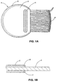
- FIG. 1A shows a comb 1 according to the invention
- the one A plurality of teeth or pins 3 comprises, and two shells or caps 7, 8, one first shell 7 and a second shell 8 (FIG. 1B), which form the handle 2.
- the number of Teeth 3 can be between 10 and 100, and preferably comb 1 comprises 33 individual teeth 3.
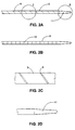
- the teeth 3 consist of two parts. An active or useful part, the ends in a conical rounded tip 11 at its end of use ( Figures 2A and 2D) and which has a substantially cylindrical body which in turn a machined surface with a helical groove 9 ( Figures 2A and 2C) or a plurality of annular (Figure 2B) grooves 10. Of the other part of each tooth 3 is the fastening part which projects into the handle 2 and there on the first shell 7 is attached.
- the teeth 3 are formed from straight, cylindrical elements with a diameter between 1.0 and 1.5 mm, and preferably with a diameter of approx. 1.25 mm with a tolerance of approx. 0.01 mm and a tolerance of straightness of the cylindrical element of 0.02 mm (FIGS. 2A and 2B), whereby the teeth 3 with such a diameter the comb 1 the high mechanical strength lend, which is needed because of the large useful length of the teeth 3.
- the teeth 3 have a roughness in their peripheral surface that preferably from a helical groove 9 (FIG. 2A) or from several parallel ones annular annular grooves 10 (Figure 2B).
- a commercially available wire straightening and cutting machine used in one of the straightening roller aisles Cutting tool on a tool carrier device with a spring for the Constant pressure is applied.
- This cutting tool rotates together with the straightening roller table the straight, cylindrical element and separates a chip from it in the form of a groove 9.
- the groove 9 finally takes the form of a screw 9 in the peripheral surface of the tooth 3.
- the thread of the helical groove 9 (FIG. 2A) is less than 4 mm and preferably less than 2 mm.
- the grooves 10 in the surface can also be done with this grinding machine generated if these are in an arrangement for the appropriate purpose is provided; in this case, the hatching consisting of grooves peripheral surface of parallel circumferential rings 10 at a distance with each other between 0.5 mm and 3 mm and preferably between 1 mm and 2 mm ( Figure 2B).
- both the grooves 9 and the grooves 10 also have a very shallow depth of less than 0.2 mm, and preferably of less than 0.1 mm to do its job of removing strangers Particles, such as lice and / or nits, that adhere to the hair to be cleaned, without damaging the hair at the same time.
- each tooth 3 with a groove 9 or with the grooves 10 in its peripheral surface is brought to a vibration polishing machine, for the final rounding of the conical tip 11 of the end of application Zahns 3, as can be seen in Figures 2A and 2D.
- the length of the cone is approx. 1 to 4 times the diameter of the cylindrical element and corresponds preferably 3 times the diameter of the cylindrical element.
- the cone ends in a hemisphere with a diameter of approximately 0.6 mm ( Figure 2D).
- the teeth 3 prepared in this way are on the inside of the first shell 7 arranged in parallel next to each other with a distance between two adjacent teeth 3 of between 50 ⁇ m and 100 ⁇ m and preferably of approximately 90 ⁇ m.
- the teeth 3 are arranged so that a useful length outside the handle 2, for combing and cleaning, between 30 mm and 50 mm, and preferably from approx. 35 mm is left, measured from the straight edge 12 (FIG. 1A) of the handle 2 and have a total length between 40 mm and 80 mm and preferably of approximately 55 mm, so that the comb 1 has a great effectiveness in relation to any to give the same type of hair to be cleaned.
- the attachment of the teeth 3 on the first shell 7 can be done using a Welding with tin or by laser welding a tooth 3 after others take place, with at least 6 mm between the straight edge 12 of the handle 2 and the start of welding must be left blank.
- the laser beam can be distinguished from both the outside of the first Shell 7, as well as from the side of the teeth 3 are applied.
- each tooth is first 5 at two 6 mm apart points and with one Welded distance of more than 6 mm from the straight edge 12 of the first shell 7, in Correspondence with the respective longitudinal axes of the teeth 3 around them correctly position and to avoid getting them out of their correct position be shifted, and then each tooth 3 with a third point 5 in the middle welded between the two other welding points 5.
- the laser is applied from the teeth 3 side, be the same with two or three laser welding spots 5 in the middle between two adjacent teeth 3 at an equidistant distance from the longitudinal axes of both Teeth 3 welded, but in any case at a distance of more than 6 mm from the straight edge 12 of the first shell 7.
- the second shell 8 placed and the round edges of the two shells 7, 8 are with a plurality of welding spots 5 welded with the help of the laser without Difference whether the teeth from the outside of the first shell 7 or from the side the teeth 3 were welded here.
Abstract
Description
Die vorliegende Erfindung betrifft einen Reinigungskamm mit Zähnen, die in ihrer peripheren Oberfläche eine Rauhigkeit aufweisen, und eine Methode zur Herstellung eines Reinigungskamms mit hoher mechanischer Festigkeit.The present invention relates to a cleaning comb with teeth, which in have a roughness on their peripheral surface, and a method for Production of a cleaning comb with high mechanical strength.
Obwohl vom Stand der Technik verschiedene Arten von Kämmen zur Reinigung von fest an den Haaren anhaftenden Teilchen, insbesondere Kämme für Läuse, bekannt sind, ist das Problem der Entfernung fremder an den Haaren von Menschen oder Tieren anhaftender Stoffe noch nicht gelöst. Das größte Problem von allen ist das der Nissen (daß heißt der Eier, der sich in menschlichen Haaren einnistenden Läuse), weil diese sich am festesten an den Haaren anhaften.Although different types of combs are known from the prior art Cleaning of particles stuck to the hair, especially combs for Lice, known to be the problem of removing strangers from the hair Substances adhering to humans or animals have not yet been removed. The biggest problem of everyone is the nits (that is, the eggs that are in human hair nesting lice) because they stick to the hair most firmly.
In der Patentschrift USA N° 4 612 945 wird ein Kamm zur Reinigung der Haare von Läusen und Nissen beschrieben. Der Kamm weist Zähne mit einem dreiecksförmigen Querschnitt auf. Der Durchmesser der Zähne nimmt von den Befestigungsenden zu den Anwendungsenden hin derart ab, daß der Abstand zwischen benachbarten Zähnen in der Nähe der Anwendungsenden größer ist als in der Nähe des Griffs. Die Zähne sind derart angeordnet, daß ihre Längsachsen parallel sind und, daß sie sich in zwei parallelen Ebenen befinden, wobei benachbarte Zähne abwechselnd zu einer der beiden Ebenen gehören. Mit dieser Anordnung wird ein Schereneffekt erreicht um die Läuse und Nissen aus den Haaren zu entfernen. Dieser Kamm hat jedoch einige Nachteile. Die Zähne haben eine relativ geringe Länge wodurch nicht in jedem Haartyp gewährleistet ist mit den Zahnspitzen bis zur Kopfhaut zu gelangen. Die Abstände zwischen den Spitzen der Anwendungsenden der Zähne sind ziemlich groß, so daß die Wirksamkeit gegen die Läuse und insbesondere gegen die Nissen erheblich vermindert ist. Außerdem weisen die Zähne durch ihre Dreiecksform scharfe Ränder auf, und haben daher die Neigung zu dem absolut unerwünschten Effekt die Oberfläche der Haare zu verletzen.In the patent specification USA No. 4 612 945 a comb for cleaning the Hair described by lice and nits. The comb has teeth with one triangular cross-section. The diameter of the teeth decreases from that Fastening ends towards the application ends such that the distance between adjacent teeth near the application ends is larger than in close to the handle. The teeth are arranged so that their longitudinal axes are parallel and that they are in two parallel planes, with adjacent teeth alternately belong to one of the two levels. With this arrangement, a Scissors effect achieved to remove the lice and nits from the hair. This However, comb has some disadvantages. The teeth have a relatively short length which is not guaranteed in every hair type with the tooth tips up to the scalp to get. The distances between the tips of the application ends of the teeth are quite large, so the effectiveness against the lice and especially against the nits is significantly reduced. In addition, the teeth show through their Triangular shape has sharp edges, and therefore have a tendency to absolutely undesirable effect of hurting the surface of the hair.
In der Patentschrift USA 4 671 303 werden ein Nissenkamm und eine Methode zur Herstellung desselben beschrieben. Der Kamm umfaßt eine Vielzahl von in einem Griff befestigten aus Metall hergestellten Zähnen, mit einem Abstand zwischen den Zähnen von ca. 100 µm bis 120 µm. Jeder Zahn ist in der Nähe seines Befestigungsendes mit einem länglichen Kanal versehen, der einem jeweiligen länglichen Verbindungselement im Griff komplementär entspricht, wodurch sichergestellt wird daß die Zähne sowohl während des Herstellung des Kammes als auch während seines Gebrauchs parallel gehalten werden. Die Zähne haben eine Nutzlänge, daß heißt einen Teil der nach außen aus dem Griff herausragt und zum Kämmen der Haare verwendet werden kann, von 9 mm oder weniger, und die Spitzen der Zähne sind hakenförmig ausgestaltet um besser die Läuse und die Nissen aus den Haaren entfernen zu können. In vielen Fällen ist die geringe Nutzlänge der Zähne nicht ausreichend um mit dem Kamm bis zur Oberfläche der Kopfhaut zu gelangen. Trotz der spezifischen Form der Zahnspitzen, hat dieser Kamm nicht die gewünschte Wirksamkeit für die Entfernung fest an den Haaren anhaftender Teilchen, wie es zum Beispiel die Nissen sind, da der Abstand zwischen den einzelnen Zähnen viel zu groß ist und die Oberfläche der Zähne glatt ist, wodurch die Mehrzahl der Nissen nicht am Kamm hängenbleibt.In the patent US 4,671,303 a nit comb and a Method for producing the same is described. The comb includes a variety of teeth made of metal fastened in a handle, at a distance between the teeth of approx. 100 µm to 120 µm. Every tooth is close to its End of attachment provided with an elongated channel that each elongated connecting element in the handle corresponds complementarily, whereby it is ensured that the teeth both during the manufacture of the comb and also be kept in parallel during its use. The teeth have one Usable length, that is, a part that protrudes outwards from the handle and to Combing the hair can be used of 9 mm or less, and the tips the teeth are hook-shaped to better lice and nits from the To be able to remove hair. In many cases, the short useful length of the teeth is not sufficient to reach the surface of the scalp with the comb. In spite of the specific shape of the tooth tips, this comb has not the desired one Effectiveness for the removal of particles adhering to the hair, such as Example the nits are because the distance between the individual teeth is much too large is and the surface of the teeth is smooth, whereby the majority of nits are not at Comb sticks.
Eine Aufgabe der vorliegenden Erfindung ist es einen Kamm zur Verfügung zu stellen mit wesentlich verbesserten Eigenschaften für die Reinigung jedes beliebigen Haartyps oder ähnlichem, von fest anhaftenden Teilchen und insbesondere von Objekten wie Nissen, die im allgemeinen sehr fest an den Haaren angehaftet sind, ohne gleichzeitig die Haare zu beschädigen.An object of the present invention is to provide a comb to provide with significantly improved properties for cleaning any Hair types or the like, of firmly adhering particles and in particular of Objects such as nits, which are generally very firmly attached to the hair, without damaging the hair at the same time.
Eine weitere Aufgabe der vorliegenden Erfindung ist es verschiedene Methoden zur Herstellung von Reinigungskämmen zu liefern, die, trotz der Tatsache daß sie Zähne mit einer relativ großer Nutzlänge haben, eine hohe mechanische Festigkeit gegen Verformungen aufweisen.Another object of the present invention is various Methods to produce cleaning combs that, despite the fact that they have teeth with a relatively large usable length, a high mechanical one Have resistance to deformation.
Eine weitere Aufgabe der vorliegenden Erfindung ist es Zähne für Kämme herzustellen, die eine periphere Oberfläche mit einer Rauhigkeit aufweisen, die insbesondere spezielle Eigenschaften für die Entfernung von fest an die Haare anhaftenden Teilchen hat.Another object of the present invention is teeth for combs to produce, which have a peripheral surface with a roughness, the in particular special properties for the removal of firmly on the hair adhering particles.
In einer bevorzugten Ausführungsform umfaßt der Reinigungskamm Zähne, die auf ihrer peripheren Oberfläche eine Rauhigkeit aufweisen, die parallel in einer Ebene angeordnet sind und einen Abstand untereinander von weniger als 100 µm aufweisen, um in effizienter Art und Weise alle fremden Elemente und kleineren Teilchen, die an den Haaren anhaften, zu entfernen. In a preferred embodiment, the cleaning comb comprises teeth, which have a roughness on their peripheral surface, which are parallel in one Are arranged level and a distance between them of less than 100 microns exhibit to all foreign items and smaller ones in an efficient manner Remove particles adhering to the hair.
Die Zähne haben eine Nutzlänge, daß heißt einen aus dem Griff herausragenden Teil, von mindestens 35 mm um wirksam zu sein, da kürzere Zähne dazu führen, daß die Reinigung von Haaren viel zu arbeitsaufwendig ist, vor allem bei dichtem und reichlichem Haar.The teeth have a usable length, that means one out of the handle protruding part, of at least 35 mm to be effective because of shorter teeth cause that the cleaning of hair is far too labor-intensive, especially at thick and abundant hair.
Die Zähne haben einen Querschnitt ohne scharfe Kanten, daher ist der Querschnitt kreisförmig oder oval, und bevorzugt müssen die Zähne eine im wesentlichen zylindrische Form haben damit sie die zu kämmenden und zu reinigenden Haare nicht beschädigen.The teeth have a cross-section without sharp edges, so that is Cross-section circular or oval, and preferably the teeth must be one in have an essentially cylindrical shape so that they have to be combed and cleaned Do not damage hair.
Die Zähne werden aus einem Material hergestellt mit einer mechanischen Festigkeit, die gleich oder größer als die von Stahl ist, und bevorzugt werden sie aus rostfreiem Stahl hergestellt mit einem Durchmesser von mindestens 1 mm, um dem Kamm, trotz der relativ großen Nutzlänge, eine hohe mechanische Festigkeit zu verleihen; damit mit dem Kamm beim Reinigen der Haare der von den Nissen geleistete Widerstand überwunden wird.The teeth are made of one material with a mechanical one Strength equal to or greater than that of steel, and they are preferred from stainless steel manufactured with a diameter of at least 1 mm to the Comb, despite the relatively large usable length, high mechanical strength to lend; with the comb when cleaning the hair of the nits resistance is overcome.
Als wesentliche Neuheit haben die Zähne des erfindungsgemäßen Kamms eine periphere Oberfläche mit einer feinen Rauhigkeit, die den Effekt hat fremde Teilchen, die an den Haaren anhaften, zu entfernen, und zwar mit einem wesentlich höheren Wirkungsgrad als es von den Zähnen aus dem Stand der Technik her bekannt ist; mit dem Reinigungskamm der vorliegenden Erfindung können, zum Beispiel, zwischen 30 und 50 % mehr Nissen entfernt werden, als es mit aus dem Stand der Technik bekannten Kämmen möglich ist.The teeth of the comb according to the invention have a major novelty a peripheral surface with a fine roughness that has the effect of foreign To remove particles that adhere to the hair, with an essential higher efficiency than that known from the teeth from the prior art is; with the cleaning comb of the present invention, for example, between 30 and 50% more nits are removed than with the prior art Technology known combs is possible.
Obwohl jede beliebige Rauhigkeit verwendet werden kann, um den Reinigungseffekt des Kammes zu verbessern, werden als bevorzugten Rauhigkeiten mit den besten Reiningungsergebnissen und/oder den geringsten Herstellungskosten, diejenigen verwendet, die aus feinen, die Nissen abschleifenden, nicht die Haare beschädigenden Rillen bestehen. Die Rillen können vorgesehen sein als schraubenförmige Rille mit einem nicht zu großen Gewindegang, oder als parallele ringförmige ringförmige Rillen mit einem genau definierten, nicht zu großen Abstand untereinander.Although any roughness can be used to make the To improve the cleaning effect of the comb are considered preferred roughness with the best cleaning results and / or the lowest manufacturing costs, used those made of fine, the nits, not the hair damaging grooves. The grooves can be provided as helical groove with a not too large thread, or as a parallel annular annular grooves with a precisely defined, not too large distance among themselves.
Bevorzugt werden die Zähne an einem Griff aus aseptischem Material befestigt, wie zum Beispiel rostfreier Stahl, der jeden Tag in heißem Wasser gekocht werden kann ohne sich zu verformen. The teeth on a handle made of aseptic material are preferred attached, such as stainless steel, which is boiled in hot water every day can become without deforming.
In einer bevorzugten Ausführungsform, beinhaltet die Methode zur Herstellung des Reinigungskammes die Schritte eine Vielzahl von Zähnen mit einer relativ großen Gesamtlänge zur Verfügung zu stellen; eine Rauhigkeit in der peripheren Oberfläche jedes Zahnes zu erzeugen; die griffentfernte Spitze an dem Anwendungsende jedes Zahnes anzuspitzen und abzurunden; die griffnahen Befestigungsenden der Zähne nebeneinander auf der Innenseite einer ersten Schale eines Griffs in einem Abstand von weniger als 100 µm voneinander getrennt derart zu positionieren, daß die Nutzlänge der Zähne außerhalb des Griffs größer als 30 mm ist; die Zähne derart leicht gegeneinander verschoben zu positionieren, daß die Gesamtheit der Anwendungsenden einen gekrümmten Rand bilden; jeden einzelnen der Zähne fest auf besagter erster Schale zu befestigen um so dem Kamm eine hohe mechanische Festigkeit zu geben; und den Griff mit einer zweiten Schale zu verschließen.In a preferred embodiment, the method includes Manufacturing the cleaning comb involves the steps of a variety of teeth with one to provide a relatively large overall length; a roughness in the peripheral Generate surface of each tooth; the handle away from the handle Sharpen and round off the application end of each tooth; the ones at hand Fastening ends of the teeth side by side on the inside of a first shell a handle at a distance of less than 100 µm apart position that the effective length of the teeth outside the handle is greater than 30 mm; to position the teeth so slightly shifted against each other that the All of the application ends form a curved edge; each the teeth firmly on said first shell to give the comb a high give mechanical strength; and the handle with a second bowl close.
Die Rauhigkeit wird in einer weiteren bevorzugten Ausführungsform mit Hilfe einer Methode erzeugt, die die Schritte enthält: ein Schneidwerkzeug auf einer Werkzeugträgervorrichtung anzubringen, wobei die Vorrichtung eine Feder aufweist, um einen gleichförmigen Druck auf einen Richtrollengang in einer Drahtricht- und schneidemaschine auszuüben; einen Zahn der Vielzahl von Zähnen in die Drahtrichtmaschine einzubringen; den besagten Richtrollengang gemeinsam mit besagtem Schneidegerät um den Zahn zu drehen, wobei aus diesem ein Span in Form einer Rille herausgetrennt wird; und gleichzeitig den Zahnes durch den Richtrollengang vorwärtszubewegen, wodurch schließlich die Rille eine Schraubenform in der peripheren Oberfläche des Zahnes bildet; und die Schritte, ausgehend von dem Einbringen eines Zahnes in die Drahtrichtmaschine, für jeden der Vielzahl von Zähnen zu wiederholen.The roughness is in a further preferred embodiment with the help created a method that includes the steps: a cutting tool on one To attach tool carrier device, the device having a spring, for a uniform pressure on a straightening roller in a wire straightening and to exercise cutting machine; one tooth of the variety of teeth in the Insert wire straightener; said straightening role together with said cutting device to rotate the tooth, from which a chip in shape a groove is cut out; and at the same time the tooth through the straightening roller table to move forward, eventually creating a screw shape in the groove peripheral surface of the tooth forms; and the steps based on that Placing a tooth in the wire straightening machine for each of the plurality of teeth to repeat.
In einer weiteren bevorzugten Ausführungsform wird die Rauhigkeit erzeugt mit Hilfe der Schritte: einen Zahn in eine Schleifmaschine einzubringen; und parallele ringförmige Rillen in die periphere Oberfläche dieses Zahnes zu schneiden.In a further preferred embodiment, the roughness is generated using the steps of: inserting a tooth into a grinding machine; and parallel to cut annular grooves in the peripheral surface of this tooth.
Um dem Kamm ein für den Verbraucher angenehmeres Anwendungsende zu verleihen, können die Zähne, während des Positionierens derselben, leicht gegeneinander versetzt angeordnet werden, so daß die Reinigungsenden der Zähne des Kammes einen gekrümmten Rand bilden. Around the comb a more comfortable end of use for the consumer To impart, the teeth, while positioning them, can easily offset from each other so that the cleaning ends of the teeth form a curved edge of the comb.
In einer weiteren der bevorzugten Ausführungsformen werden die Zähne mit Hilfe eines Lasers auf die erste Schale geschweißt. Der Laserstrahl kann von der Außenseite der Schale her angewandt werden, oder er kann von der Seite der Zähne angewandt werden, in letzterem Falle jedoch nur zwischen zwei jeweils benachbarten Zähnen, um nicht während der Anwendung des Lasers die Struktur der Zähne zu verändern. In diesen Ausführungsformen wird der Griff dadurch verschlossen, daß die zweite Schale mit Hilfe des Lasers auf die erste Schale geschweißt wird.In another of the preferred embodiments, the teeth are with Welded onto the first shell using a laser. The laser beam can from the Be applied outside of the shell, or it can be from the side of the teeth be used, in the latter case, however, only between two neighboring ones Teeth so as not to increase the structure of the teeth during the application of the laser change. In these embodiments, the handle is closed by the second shell is welded onto the first shell using the laser.
In einer weiteren bevorzugten Ausführungsform der vorliegenden Erfindung werden die Zähne mit Zinn aufgeschweißt, wobei die Schweißung von der Seite der Zähne her angewandt wird. In diesem Fall wird der Griff, nach Einfügen eines Zwischenstücks aus Plastik zwischen der ersten und der zweiten Schale, mit Hilfe eines Anpreßdrucks verschlossen, wobei das Zwischenstück aus Plastik den Zweck hat den Anpreßdruck zu tragen.In a further preferred embodiment of the present invention the teeth are welded with tin, the weld from the side of the Teeth forth is applied. In this case, the handle, after inserting a Plastic adapter between the first and the second shell, with the help of a Contact pressure closed, whereby the intermediate piece made of plastic has the purpose Wear contact pressure.
Die vorgenannten Aufgaben werden mit dem Kamm der vorliegenden Erfindung erfüllt, welcher in den nachfolgenden Abbildungen dargestellt wird, und es zeigen:
- die Figur 1A:
- eine Aufsicht auf den erfindungsgemäßen Kamm von der Seite der ersten Schale;
- die Figur 1B:
- eine Teilseitenansicht des Reinigungskamms in einem Schnitt längs der Linie I-I der Figur 1A;
- die Figur 2A:
- eine Seitenansicht eines Zahns mit einer Rauhigkeit in Form einer schraubenförmigen Rille;
- die Figur 2B:
- eine Seitenansicht eines Zahns mit einer Rauhigkeit in Form paralleler ringförmiger Rillen;
- die Figur 2C:
- eine vergrößerte Sicht des Ausschnitts II der Figur 2A; und
- die Figur 2D:
- eine vergrößerte Sicht des Ausschnitts III der Figur 2A.
- Figure 1A:
- a top view of the comb according to the invention from the side of the first shell;
- FIG. 1B:
- a partial side view of the cleaning comb in a section along the line II of Figure 1A;
- Figure 2A:
- a side view of a tooth with a roughness in the form of a helical groove;
- the figure 2B:
- a side view of a tooth with a roughness in the form of parallel annular grooves;
- the figure 2C:
- an enlarged view of section II of Figure 2A; and
- the figure 2D:
- an enlarged view of section III of Figure 2A.
In der Figur 1A ist ein erfindungsgemäßer Kamm 1 dargestellt, der eine
Vielzahl von Zähnen oder Stiften 3 umfaßt, und zwei Schalen oder Kappen 7, 8, eine
erste Schale 7 und eine zweite Schale 8 (Fig. 1B), die den Griff 2 bilden. Die Anzahl der
Zähne 3 kann zwischen 10 und 100 betragen, und bevorzugt umfaßt der Kamm 1 33
einzelne Zähne 3.FIG. 1A shows a comb 1 according to the invention, the one
A plurality of teeth or pins 3 comprises, and two shells or
Die Zähne 3 bestehen aus zwei Teilen. Ein aktiver oder nützlicher Teil, der
an seinem Anwendungsende in einer konischen abgerundeten Spitze 11 endet
(Figuren 2A und 2D) und der einen im wesentlichen zylindrischen Körper hat, welcher
seinerseits eine mechanisch bearbeiteten Oberfläche mit einer schraubenförmigen Rille
9 (Figuren 2A und 2C) oder mehreren ringförmigen (Figur 2B) Rillen 10 aufweist. Der
andere Teil jedes Zahns 3 ist der Befestigungsteil der in den Griff 2 ragt und dort an der
ersten Schale 7 befestigt ist.The
Die Zähne 3 werden aus geraden, zylindrischen Elementen gebildet mit
einem Durchmesser zwischen 1,0 und 1,5 mm, und bevorzugt mit einem Durchmesser
von ca. 1,25 mm mit einer Toleranz von ca. 0,01 mm, und einer Toleranz der Geradheit
des zylindrischen Elements von 0,02 mm (Figuren 2A und 2B), wodurch die Zähne 3
mit einem solchen Durchmesser dem Kamm 1 die hohe mechanische Festigkeit
verleihen, die wegen der großen Nutzlänge der Zähne 3 benötigt wird.The
Die Zähne 3 weisen in ihrer peripheren Oberfläche eine Rauhigkeit auf, die
bevorzugt aus einer schraubenförmigen Rille 9 (Figur 2A) oder aus mehreren parallelen
ringförmigen ringförmigen Rillen 10 (Figur 2B) besteht.The
Zur Herstellung eines Zahnes wird eine handelsübliche Drahtricht- und schneidemaschine verwendet, in der an einem der Richtrollengänge ein Schneidwerkzeug auf einer Werkzeugträgervorrichtung mit einer Feder für die Ausübung eines konstanten Druckes angebracht wird.A commercially available wire straightening and cutting machine used in one of the straightening roller aisles Cutting tool on a tool carrier device with a spring for the Constant pressure is applied.
Dieses Schneidwerkzeug dreht sich gemeinsam mit dem Richtrollengang um
das gerade, zylindrische Element und trennt aus diesem einen Span in Form einer Rille
9. Durch das Vorwärtsbewegen des geraden, zylindrischen Elements durch den
Richtrollengang, erhält die Rille 9 schließlich die Form einer Schraube 9 in der
peripheren Oberfläche des Zahnes 3. Der Gewindegang der schraubenförmigen Rille 9
(Figur 2A) ist kleiner als 4 mm und bevorzugt kleiner als 2 mm.This cutting tool rotates together with the straightening roller table
the straight, cylindrical element and separates a chip from it in the form of a groove
9. By moving the straight, cylindrical element through the
Straightening roller conveyor, the groove 9 finally takes the form of a screw 9 in the
peripheral surface of the
Bis hierher bleibt das gerade Element mit seiner mit einer
schraubenförmigen Rille versehenen Oberfläche in seiner zylindrischen Form erhalten.
Dieses Element wird nun in eine spitzenlose Schleifmaschine eingebracht, wo die
Spitze 11 mit einem oder mehreren Schnitten geschliffen wird.So far the straight element remains with its one
helical groove provided surface in its cylindrical shape.
This element is now placed in a centerless grinding machine, where the
Die Rillen 10 in der Oberfläche können auch mit dieser Schleifmaschine
erzeugt werden, wenn diese in einer Anordnung für den entsprechenden Zweck
vorgesehen wird; in diesem Fall besteht die aus Rillen bestehende Schraffur der
peripheren Oberfläche aus parallelen Umfangsringen 10 mit einem Abstand
untereinander zwischen 0,5 mm und 3 mm und bevorzugt zwischen 1 mm und 2 mm
(Figur 2B).The
Wie man aus der Figur 2C erkennen kann haben sowohl die Rillen 9 als
auch die Rillen 10 eine sehr geringe Tiefe von weniger als 0,2 mm, und bevorzugt von
weniger als 0,1 mm um ihre Aufgabe zu erfüllen, nämlich die Entfernung von fremden
Teilchen, wie Läuse und/oder Nissen, die an den zu reinigenden Haaren anhaften,
ohne dabei gleichzeitig die Haare zu beschädigen.As can be seen from Figure 2C, both the grooves 9 and
the
Danach wird jeder Zahn 3, der mit einer Rille 9 oder mit den Rillen 10 in
seiner peripheren Oberfläche versehen ist, zu einer Vibrationspoliermaschine gebracht,
für die endgültige Abrundung der konischen Spitze 11 des Anwendungsende des
Zahns 3, wie sie in den Figuren 2A und 2D zu sehen ist. Die Länge des Konus beträgt
ca. das 1- bis 4-fache des Durchmessers des zylindrischen Elements und entspricht
bevorzugt dem 3-fachen des Durchmessers des zylindrischen Elements. Der Konus
endet in einer Halbkugel mit einem Durchmesser von ca. 0,6 mm (Figur 2D).Thereafter, each
Die auf diese Weise vorbereiteten Zähne 3 werden auf der Innenseite der
ersten Schale 7 parallel nebeneinander angeordnet mit einem Abstand zwischen zwei
benachbarten Zähnen 3 von zwischen 50 µm und 100 µm und bevorzugt von ca. 90
µm. Die Zähne 3 werden so angeordnet, daß außerhalb des Griffs 2 eine Nutzlänge,
die zum Kämmen und Reinigen dient, zwischen 30 mm und 50 mm, und bevorzugt von
ca. 35 mm gelassen wird, gemessen von dem geraden Rand 12 (Figur 1A) des Griffs 2
und haben eine Gesamtlänge zwischen 40 mm und 80 mm und bevorzugt von ca. 55
mm, um damit dem Kamm 1 eine große Wirksamkeit in Bezug auf jeden beliebigen mit
demselben zu reinigenden Haartyp zu verleihen.The
Beim Anordnen der Zähne 3 auf der ersten Schale 7 werden dieselben leicht
versetzt gegenüber dem jeweils benachbarten Zahn 3 positioniert, so daß ihre
Anwendungsenden als Gesamtheit einen gekrümmten Rand 6 bilden (Figur 1A).When the
Die Befestigung der Zähne 3 auf der ersten Schale 7 kann mit Hilfe einer
Schweißung mit Zinn oder durch eine Laserschweißung eines Zahnes 3 nach dem
anderen erfolgen, wobei mindestens 6 mm zwischen dem geraden Rand 12 des Griffs
2 und dem Beginn der Schweißung freigelassen werden müssen.The attachment of the
Im Falle, der Verschweißung der Zähne 3 auf der ersten Schale 7 mit dem
Laser, kann der Laserstrahl ohne Unterschied sowohl von der Außenseite der ersten
Schale 7, als auch von der Seite der Zähne 3 angewandt werden. In the case of welding the
Wenn der Laser von der Außenseite der ersten Schale 7 angewandt wird,
wird jeder Zahn zuerst an zwei 6 mm von einander entfernten Punkten 5 und mit einem
Abstand von mehr als 6 mm vom geraden Rand 12 der ersten Schale 7 verschweißt, in
Übereinstimmung mit den jeweiligen Längsachsen der Zähne 3 um dieselben richtig zu
positionieren und um zu vermeiden, daß sie wieder aus ihrer korrekten Position
verschoben werden, und dann wird jeder Zahn 3 mit einem dritten Punkt 5 in der Mitte
zwischen den beiden anderen Schweißpunkten 5 verschweißt.When the laser is applied from the outside of the
Wenn der Laser von der Seite der Zähne 3 angewandt wird, werden
dieselben mit zwei oder drei Laserschweißpunkten 5 in der Mitte zwischen zwei
benachbarten Zähnen 3 in einem äquidistanten Abstand zu den Längsachsen beider
Zähne 3 festgeschweißt, aber in jedem Falle in einem Abstand von mehr als 6 mm vom
geraden Rand 12 der ersten Schale 7.If the laser is applied from the
Nach dem Verschweißen der Zähne 3 auf der ersten Schale 7, wird die
zweite Schale 8 aufgelegt und die runden Ränder der beiden Schalen 7, 8 werden mit
einer Vielzahl von Schweißpunkten 5 mit Hilfe des Lasers verschweißt, ohne
Unterschied ob die Zähne von der Außenseite der ersten Schale 7 oder von der Seite
der Zähne 3 her festgeschweißt wurden.After welding the
In dem Fall in dem die Zähne 3 mit Zinn verschweißt werden, wird die
Schweißung von der Seite der Zähne 3 angewandt. Danach wird der Griff 2
geschlossen, in dem die zweite Schale 8 unter Druck auf die erste Schale 7 gepreßt
wird. In diesem Fall, wird vor der Anwendung des Anpreßdrucks ein in den Figuren
nicht dargestelltes Zwischenstück aus Plastik zwischen beiden Schalen 7, 8 eingefügt,
welche den Anpreßdruck aufnehmen und tragen muß.In the case where the
Es versteht sich, daß die vorstehende detaillierte Beschreibung nur zu Zwecken der beispielhaften Anschauung dient, und daß Änderungen und Abweichungen von derselben möglich sind, ohne sich von dem Geist und Inhalt der vorliegenden Erfindung zu entfernen.It should be understood that the foregoing detailed description is only too For the purposes of example, and that changes and Deviations from the same are possible without departing from the spirit and content of the remove present invention.
Claims (26)
Applications Claiming Priority (2)
| Application Number | Priority Date | Filing Date | Title |
|---|---|---|---|
| US08/904,762 US5873374A (en) | 1997-08-01 | 1997-08-01 | Cleaning comb with needles that are rugged on their peripheral surface and method of manufacturing a high mechanical strength cleaning comb |
| US904762 | 1997-08-01 |
Publications (3)
| Publication Number | Publication Date |
|---|---|
| EP0894450A2 true EP0894450A2 (en) | 1999-02-03 |
| EP0894450A3 EP0894450A3 (en) | 1999-07-07 |
| EP0894450B1 EP0894450B1 (en) | 2003-05-07 |
Family
ID=25419730
Family Applications (1)
| Application Number | Title | Priority Date | Filing Date |
|---|---|---|---|
| EP98114393A Expired - Lifetime EP0894450B1 (en) | 1997-08-01 | 1998-07-31 | Cleaning comb with teeth having a predetermined roughness on their outer surface and method of manufacturing a cleaning comb of high mechanical strength |
Country Status (16)
| Country | Link |
|---|---|
| US (1) | US5873374A (en) |
| EP (1) | EP0894450B1 (en) |
| JP (1) | JP3254424B2 (en) |
| AR (1) | AR013275A1 (en) |
| AT (1) | ATE239402T1 (en) |
| AU (1) | AU709268B2 (en) |
| BR (1) | BR9803731A (en) |
| CA (1) | CA2244552C (en) |
| CO (1) | CO4850556A1 (en) |
| DE (1) | DE59808224D1 (en) |
| DK (1) | DK0894450T3 (en) |
| ES (1) | ES2199392T3 (en) |
| IL (1) | IL125553A (en) |
| PE (1) | PE102999A1 (en) |
| PT (1) | PT894450E (en) |
| UY (1) | UY25117A1 (en) |
Cited By (1)
| Publication number | Priority date | Publication date | Assignee | Title |
|---|---|---|---|---|
| US20210212434A1 (en) * | 2017-07-14 | 2021-07-15 | Lacuna S.A. | Comb for the treatment of pediculosis |
Families Citing this family (15)
| Publication number | Priority date | Publication date | Assignee | Title |
|---|---|---|---|---|
| FR2752332B1 (en) * | 1996-08-12 | 1998-09-11 | Commissariat Energie Atomique | DEVICE FOR PICKING UP WAFERS AND METHOD FOR IMPLEMENTING THE DEVICE |
| US20030229321A1 (en) * | 2002-06-05 | 2003-12-11 | Timothy Simon | Needle with slotted tip |
| AR042223A1 (en) * | 2003-11-27 | 2005-06-15 | Lanne Carlos Alberto | RIGID HAIR FOR HAIR CLEANING, WITH EXTREME MICROTEXTURED TEETH |
| NZ575509A (en) * | 2006-08-23 | 2010-10-29 | Moshe Maor | A lice comb |
| US20090314305A1 (en) * | 2008-06-20 | 2009-12-24 | Frank Bachrach | Lice and nit removal comb |
| WO2010138144A1 (en) * | 2009-05-26 | 2010-12-02 | American Comb Corp. | Lice and nit removal comb with square shaped metal teeth |
| AU2009355520B2 (en) * | 2009-11-23 | 2015-04-02 | Jorge Reinaldo Burchakchi | Comb for treating pediculosis |
| US20160051027A1 (en) * | 2014-08-19 | 2016-02-25 | Pam Skinner | System and method for eliminating lice and nits |
| US9474250B1 (en) * | 2015-05-29 | 2016-10-25 | Jennifer L. Tipton | Animal grooming tool with wave pattern blade teeth |
| US10194738B2 (en) | 2015-11-03 | 2019-02-05 | Patricia E. Steiner | Brush for lice or other parasitic insects |
| USD854244S1 (en) * | 2018-04-27 | 2019-07-16 | Pam Skinner | Lice comb |
| USD923243S1 (en) | 2019-11-15 | 2021-06-22 | Tec Laboratories, Inc. | Lice comb |
| EP3912511A1 (en) | 2020-05-23 | 2021-11-24 | Lars Magnus Holmberg | A comb |
| SE545485C2 (en) * | 2020-05-23 | 2023-09-26 | Lars Magnus Holmberg | Lice comb |
| USD936285S1 (en) | 2020-12-29 | 2021-11-16 | Tec Laboratories, Inc. | Double-sided lice comb with cover |
Citations (2)
| Publication number | Priority date | Publication date | Assignee | Title |
|---|---|---|---|---|
| US4612945A (en) | 1985-02-20 | 1986-09-23 | American Comb Corporation | Comb |
| US4671303A (en) | 1985-03-13 | 1987-06-09 | Albert Saferstein | Nit comb and method of producing same |
Family Cites Families (9)
| Publication number | Priority date | Publication date | Assignee | Title |
|---|---|---|---|---|
| DE339538C (en) * | 1921-07-30 | Fritz Mueckenhaupt | Comb | |
| DE634125C (en) * | 1932-05-13 | 1936-08-17 | Ernst Schlaechter | Comb for cleaning the hair and scalp |
| US2270528A (en) * | 1940-02-06 | 1942-01-20 | Kirschenbaum Samuel | Comb |
| NL63792C (en) * | 1945-11-29 | |||
| GB604963A (en) * | 1945-12-11 | 1948-07-13 | James Maxwell Clark | Improvements in or relating to hair combs |
| US2605773A (en) * | 1950-12-08 | 1952-08-05 | Thomas C | Comb |
| US5318051A (en) * | 1992-01-17 | 1994-06-07 | Sunbelt Precision Products, Inc. | Comb structure and method of making the same |
| US5353817A (en) * | 1992-03-15 | 1994-10-11 | Mepro Epilady Ltd. | Hair grooming device |
| BR7601136U (en) * | 1996-01-16 | 1998-07-14 | Chemotecnica Sintyal S A | Neat remover fine comb |
-
1997
- 1997-08-01 US US08/904,762 patent/US5873374A/en not_active Expired - Lifetime
-
1998
- 1998-07-28 IL IL12555398A patent/IL125553A/en not_active IP Right Cessation
- 1998-07-29 CO CO98043169A patent/CO4850556A1/en unknown
- 1998-07-29 AU AU78561/98A patent/AU709268B2/en not_active Expired
- 1998-07-30 CA CA002244552A patent/CA2244552C/en not_active Expired - Lifetime
- 1998-07-31 ES ES98114393T patent/ES2199392T3/en not_active Expired - Lifetime
- 1998-07-31 AT AT98114393T patent/ATE239402T1/en active IP Right Revival
- 1998-07-31 PE PE1998000687A patent/PE102999A1/en not_active IP Right Cessation
- 1998-07-31 DE DE59808224T patent/DE59808224D1/en not_active Expired - Lifetime
- 1998-07-31 DK DK98114393T patent/DK0894450T3/en active
- 1998-07-31 EP EP98114393A patent/EP0894450B1/en not_active Expired - Lifetime
- 1998-07-31 AR ARP980103816A patent/AR013275A1/en unknown
- 1998-07-31 PT PT98114393T patent/PT894450E/en unknown
- 1998-07-31 UY UY25117A patent/UY25117A1/en not_active IP Right Cessation
- 1998-07-31 BR BR9803731-5A patent/BR9803731A/en not_active IP Right Cessation
- 1998-08-03 JP JP21916298A patent/JP3254424B2/en not_active Expired - Lifetime
Patent Citations (2)
| Publication number | Priority date | Publication date | Assignee | Title |
|---|---|---|---|---|
| US4612945A (en) | 1985-02-20 | 1986-09-23 | American Comb Corporation | Comb |
| US4671303A (en) | 1985-03-13 | 1987-06-09 | Albert Saferstein | Nit comb and method of producing same |
Cited By (1)
| Publication number | Priority date | Publication date | Assignee | Title |
|---|---|---|---|---|
| US20210212434A1 (en) * | 2017-07-14 | 2021-07-15 | Lacuna S.A. | Comb for the treatment of pediculosis |
Also Published As
| Publication number | Publication date |
|---|---|
| UY25117A1 (en) | 1998-08-07 |
| IL125553A0 (en) | 1999-03-12 |
| AR013275A1 (en) | 2000-12-13 |
| PT894450E (en) | 2003-09-30 |
| IL125553A (en) | 2001-11-25 |
| ES2199392T3 (en) | 2004-02-16 |
| DK0894450T3 (en) | 2003-08-25 |
| BR9803731A (en) | 1999-11-16 |
| ATE239402T1 (en) | 2003-05-15 |
| PE102999A1 (en) | 1999-11-05 |
| US5873374A (en) | 1999-02-23 |
| EP0894450A3 (en) | 1999-07-07 |
| JP3254424B2 (en) | 2002-02-04 |
| CA2244552A1 (en) | 1999-02-01 |
| JPH1199013A (en) | 1999-04-13 |
| CA2244552C (en) | 2002-06-25 |
| EP0894450B1 (en) | 2003-05-07 |
| AU7856198A (en) | 1999-02-25 |
| AU709268B2 (en) | 1999-08-26 |
| DE59808224D1 (en) | 2003-06-12 |
| CO4850556A1 (en) | 1999-10-26 |
Similar Documents
| Publication | Publication Date | Title |
|---|---|---|
| EP0894450B1 (en) | Cleaning comb with teeth having a predetermined roughness on their outer surface and method of manufacturing a cleaning comb of high mechanical strength | |
| EP0444436B1 (en) | Treatment of bristles | |
| DE60201927T3 (en) | Device, in particular brush, for applying a product to keratinic fibers | |
| DE602004001252T2 (en) | Brush and device for receiving and applying with such a brush | |
| EP1301103B1 (en) | Treatment element for an appliance for cleaning dental interstices, a method and device for the production thereof | |
| DE3620702A1 (en) | GARNITURE FOR TEXTILE PREPARATION MACHINES, ESPECIALLY KAEMM MACHINES, CARDS OR THE LIKE. | |
| EP3177228B1 (en) | Interdental cleaner and method for producing same | |
| EP1389436A1 (en) | Mascara brush | |
| DE3034164C2 (en) | Setting for gemstones or the like, as well as methods for setting gemstones | |
| EP1318735A1 (en) | Method for producing bristle products | |
| DE69929921T2 (en) | Endodontic instrument | |
| DE19963600B4 (en) | Process for making a mascara brush | |
| DE202016103629U1 (en) | Cosmetic applicator with flocking and bristles | |
| DE102018101085A1 (en) | Rotated brush, method for producing a screwed brush and apparatus for producing a screwed brush | |
| EP3174434B1 (en) | Wire-core applicator having multi-material bristles | |
| DE2714468C2 (en) | Metal strips with spaced apart blades for use in the manufacture of surgical blades and methods of reprocessing | |
| DE69628347T2 (en) | TOOTHBRUSH | |
| DE112018003938T5 (en) | METHOD FOR PRODUCING A SHEET FOR USE IN TONGUE PLAQUE CLEANERS | |
| DE3873935T9 (en) | A knife for a hair clipper. | |
| DE3248256C2 (en) | ||
| DE4441985A1 (en) | Method of manufacturing brushes, esp. toothbrushes | |
| EP1173082B1 (en) | Method for conditioning bristles | |
| DE3506231C2 (en) | Process for the production of roller brushes | |
| DE202004013709U1 (en) | Device to process bristles esp. of toothbrushes consists of rotating plate with ceramic pegs to smooth sharp bristle ends | |
| DE19927708C2 (en) | Brush for cleaning dentures |
Legal Events
| Date | Code | Title | Description |
|---|---|---|---|
| PUAI | Public reference made under article 153(3) epc to a published international application that has entered the european phase |
Free format text: ORIGINAL CODE: 0009012 |
|
| 17P | Request for examination filed |
Effective date: 19981113 |
|
| AK | Designated contracting states |
Kind code of ref document: A2 Designated state(s): AT BE CH DE DK ES FI FR GB GR IE IT LI NL PT SE |
|
| AX | Request for extension of the european patent |
Free format text: AL;LT;LV;MK;RO;SI |
|
| PUAL | Search report despatched |
Free format text: ORIGINAL CODE: 0009013 |
|
| AK | Designated contracting states |
Kind code of ref document: A3 Designated state(s): AT BE CH CY DE DK ES FI FR GB GR IE IT LI LU MC NL PT SE |
|
| AX | Request for extension of the european patent |
Free format text: AL;LT;LV;MK;RO;SI |
|
| AKX | Designation fees paid |
Free format text: AT BE CH DE DK ES FI FR GB GR IE IT LI NL PT SE |
|
| 17Q | First examination report despatched |
Effective date: 20010620 |
|
| GRAH | Despatch of communication of intention to grant a patent |
Free format text: ORIGINAL CODE: EPIDOS IGRA |
|
| GRAH | Despatch of communication of intention to grant a patent |
Free format text: ORIGINAL CODE: EPIDOS IGRA |
|
| GRAA | (expected) grant |
Free format text: ORIGINAL CODE: 0009210 |
|
| AK | Designated contracting states |
Designated state(s): AT BE CH DE DK ES FI FR GB GR IE IT LI NL PT SE |
|
| REG | Reference to a national code |
Ref country code: GB Ref legal event code: FG4D Free format text: NOT ENGLISH |
|
| REG | Reference to a national code |
Ref country code: CH Ref legal event code: EP |
|
| BECA | Be: change of holder's address |
Owner name: *ASSISTANCE S.R.L.AV. CORDOBA 950 - 14TH FLOOR, OF Effective date: 20030507 |
|
| REG | Reference to a national code |
Ref country code: IE Ref legal event code: FG4D Free format text: GERMAN |
|
| REF | Corresponds to: |
Ref document number: 59808224 Country of ref document: DE Date of ref document: 20030612 Kind code of ref document: P |
|
| REG | Reference to a national code |
Ref country code: SE Ref legal event code: TRGR |
|
| REG | Reference to a national code |
Ref country code: CH Ref legal event code: NV Representative=s name: PATENTANWAELTE FELDMANN & PARTNER AG |
|
| REG | Reference to a national code |
Ref country code: DK Ref legal event code: T3 |
|
| GBT | Gb: translation of ep patent filed (gb section 77(6)(a)/1977) | ||
| REG | Reference to a national code |
Ref country code: GR Ref legal event code: EP Ref document number: 20030403052 Country of ref document: GR |
|
| REG | Reference to a national code |
Ref country code: PT Ref legal event code: SC4A Free format text: AVAILABILITY OF NATIONAL TRANSLATION Effective date: 20030806 |
|
| REG | Reference to a national code |
Ref country code: ES Ref legal event code: FG2A Ref document number: 2199392 Country of ref document: ES Kind code of ref document: T3 |
|
| ET | Fr: translation filed | ||
| PLBE | No opposition filed within time limit |
Free format text: ORIGINAL CODE: 0009261 |
|
| STAA | Information on the status of an ep patent application or granted ep patent |
Free format text: STATUS: NO OPPOSITION FILED WITHIN TIME LIMIT |
|
| 26N | No opposition filed |
Effective date: 20040210 |
|
| PGFP | Annual fee paid to national office [announced via postgrant information from national office to epo] |
Ref country code: BE Payment date: 20070806 Year of fee payment: 10 |
|
| PGFP | Annual fee paid to national office [announced via postgrant information from national office to epo] |
Ref country code: GR Payment date: 20070730 Year of fee payment: 10 |
|
| REG | Reference to a national code |
Ref country code: PT Ref legal event code: MM4A Free format text: LAPSE DUE TO NON-PAYMENT OF FEES Effective date: 20090202 |
|
| REG | Reference to a national code |
Ref country code: CH Ref legal event code: PL |
|
| REG | Reference to a national code |
Ref country code: DK Ref legal event code: EBP |
|
| GBPC | Gb: european patent ceased through non-payment of renewal fee |
Effective date: 20080731 |
|
| NLV4 | Nl: lapsed or anulled due to non-payment of the annual fee |
Effective date: 20090201 |
|
| EUG | Se: european patent has lapsed | ||
| REG | Reference to a national code |
Ref country code: IE Ref legal event code: MM4A |
|
| PG25 | Lapsed in a contracting state [announced via postgrant information from national office to epo] |
Ref country code: DE Free format text: LAPSE BECAUSE OF NON-PAYMENT OF DUE FEES Effective date: 20090203 Ref country code: AT Free format text: LAPSE BECAUSE OF NON-PAYMENT OF DUE FEES Effective date: 20080731 |
|
| REG | Reference to a national code |
Ref country code: FR Ref legal event code: ST Effective date: 20090331 |
|
| REG | Reference to a national code |
Ref country code: PT Ref legal event code: NF4A Free format text: RESTITUTIO IN INTEGRUM Effective date: 20090519 |
|
| PG25 | Lapsed in a contracting state [announced via postgrant information from national office to epo] |
Ref country code: PT Free format text: LAPSE BECAUSE OF NON-PAYMENT OF DUE FEES Effective date: 20090202 Ref country code: FI Free format text: LAPSE BECAUSE OF NON-PAYMENT OF DUE FEES Effective date: 20080731 |
|
| REG | Reference to a national code |
Ref country code: GB Ref legal event code: S28 Free format text: APPLICATION FILED |
|
| PG25 | Lapsed in a contracting state [announced via postgrant information from national office to epo] |
Ref country code: LI Free format text: LAPSE BECAUSE OF NON-PAYMENT OF DUE FEES Effective date: 20080731 Ref country code: GR Free format text: LAPSE BECAUSE OF NON-PAYMENT OF DUE FEES Effective date: 20090204 Ref country code: GB Free format text: LAPSE BECAUSE OF NON-PAYMENT OF DUE FEES Effective date: 20080731 Ref country code: CH Free format text: LAPSE BECAUSE OF NON-PAYMENT OF DUE FEES Effective date: 20080731 |
|
| PG25 | Lapsed in a contracting state [announced via postgrant information from national office to epo] |
Ref country code: IE Free format text: LAPSE BECAUSE OF NON-PAYMENT OF DUE FEES Effective date: 20080731 Ref country code: DK Free format text: LAPSE BECAUSE OF NON-PAYMENT OF DUE FEES Effective date: 20080731 |
|
| NLXE | Nl: other communications concerning ep-patents (part 3 heading xe) |
Free format text: A REQUEST FOR RESTORATION TO THE PRIOR STATE (ARTICLE 23 OF THE PATENTS ACT 1995) HAS BEEN FILED ON 20090522 |
|
| PG25 | Lapsed in a contracting state [announced via postgrant information from national office to epo] |
Ref country code: FR Free format text: LAPSE BECAUSE OF NON-PAYMENT OF DUE FEES Effective date: 20080731 |
|
| PGRI | Patent reinstated in contracting state [announced from national office to epo] |
Ref country code: PT Effective date: 20090519 Ref country code: AT Effective date: 20090706 |
|
| REG | Reference to a national code |
Ref country code: IE Ref legal event code: NE4A |
|
| REG | Reference to a national code |
Ref country code: GB Ref legal event code: S28 Free format text: RESTORATION ALLOWED Effective date: 20090820 |
|
| REG | Reference to a national code |
Ref country code: FR Ref legal event code: RN |
|
| REG | Reference to a national code |
Ref country code: FR Ref legal event code: FC |
|
| PGRI | Patent reinstated in contracting state [announced from national office to epo] |
Ref country code: DE Effective date: 20090810 |
|
| REG | Reference to a national code |
Ref country code: IE Ref legal event code: NF4A Effective date: 20091204 |
|
| PGRI | Patent reinstated in contracting state [announced from national office to epo] |
Ref country code: IE Effective date: 20091204 |
|
| PG25 | Lapsed in a contracting state [announced via postgrant information from national office to epo] |
Ref country code: SE Free format text: LAPSE BECAUSE OF NON-PAYMENT OF DUE FEES Effective date: 20080801 Ref country code: BE Free format text: LAPSE BECAUSE OF NON-PAYMENT OF DUE FEES Effective date: 20080731 |
|
| PGRI | Patent reinstated in contracting state [announced from national office to epo] |
Ref country code: FR Effective date: 20100531 |
|
| REG | Reference to a national code |
Ref country code: DK Ref legal event code: EGE |
|
| PGRI | Patent reinstated in contracting state [announced from national office to epo] |
Ref country code: FI Effective date: 20090730 |
|
| REG | Reference to a national code |
Ref country code: CH Ref legal event code: AEN Free format text: DAS PATENT IST AM 04.02.2011 GESTUETZT AUF DAS AM 09.09.2009 EINGEREICHTE WIEDEREINSETZUNGSGESUCH AUF GRUND VON ART. 47 PATG WIEDER IN KRAFT GESETZT WO |
|
| PGRI | Patent reinstated in contracting state [announced from national office to epo] |
Ref country code: CH Effective date: 20110204 |
|
| PGRI | Patent reinstated in contracting state [announced from national office to epo] |
Ref country code: SE Effective date: 20090921 |
|
| REG | Reference to a national code |
Ref country code: FR Ref legal event code: PLFP Year of fee payment: 18 |
|
| REG | Reference to a national code |
Ref country code: NL Ref legal event code: RD2H Effective date: 20100121 |
|
| REG | Reference to a national code |
Ref country code: FR Ref legal event code: PLFP Year of fee payment: 19 |
|
| REG | Reference to a national code |
Ref country code: FR Ref legal event code: PLFP Year of fee payment: 20 |
|
| PGFP | Annual fee paid to national office [announced via postgrant information from national office to epo] |
Ref country code: GB Payment date: 20170619 Year of fee payment: 20 Ref country code: FR Payment date: 20170530 Year of fee payment: 20 Ref country code: IE Payment date: 20170509 Year of fee payment: 20 Ref country code: CH Payment date: 20170612 Year of fee payment: 20 |
|
| PGFP | Annual fee paid to national office [announced via postgrant information from national office to epo] |
Ref country code: PT Payment date: 20170509 Year of fee payment: 20 Ref country code: NL Payment date: 20170630 Year of fee payment: 20 Ref country code: IT Payment date: 20170525 Year of fee payment: 20 |
|
| PGFP | Annual fee paid to national office [announced via postgrant information from national office to epo] |
Ref country code: ES Payment date: 20170803 Year of fee payment: 20 Ref country code: DE Payment date: 20170522 Year of fee payment: 20 Ref country code: FI Payment date: 20170710 Year of fee payment: 20 |
|
| PGFP | Annual fee paid to national office [announced via postgrant information from national office to epo] |
Ref country code: AT Payment date: 20170718 Year of fee payment: 20 Ref country code: SE Payment date: 20170718 Year of fee payment: 20 Ref country code: DK Payment date: 20170718 Year of fee payment: 20 |
|
| REG | Reference to a national code |
Ref country code: DE Ref legal event code: R071 Ref document number: 59808224 Country of ref document: DE |
|
| REG | Reference to a national code |
Ref country code: NL Ref legal event code: MK Effective date: 20180730 |
|
| REG | Reference to a national code |
Ref country code: DK Ref legal event code: EUP Effective date: 20180731 |
|
| REG | Reference to a national code |
Ref country code: CH Ref legal event code: PL |
|
| REG | Reference to a national code |
Ref country code: GB Ref legal event code: PE20 Expiry date: 20180730 Ref country code: IE Ref legal event code: MK9A |
|
| REG | Reference to a national code |
Ref country code: AT Ref legal event code: MK07 Ref document number: 239402 Country of ref document: AT Kind code of ref document: T Effective date: 20180731 |
|
| REG | Reference to a national code |
Ref country code: SE Ref legal event code: EUG |
|
| PG25 | Lapsed in a contracting state [announced via postgrant information from national office to epo] |
Ref country code: IE Free format text: LAPSE BECAUSE OF EXPIRATION OF PROTECTION Effective date: 20180731 Ref country code: PT Free format text: LAPSE BECAUSE OF EXPIRATION OF PROTECTION Effective date: 20180808 |
|
| PG25 | Lapsed in a contracting state [announced via postgrant information from national office to epo] |
Ref country code: GB Free format text: LAPSE BECAUSE OF EXPIRATION OF PROTECTION Effective date: 20180730 |
|
| REG | Reference to a national code |
Ref country code: ES Ref legal event code: FD2A Effective date: 20200803 |
|
| PG25 | Lapsed in a contracting state [announced via postgrant information from national office to epo] |
Ref country code: ES Free format text: LAPSE BECAUSE OF EXPIRATION OF PROTECTION Effective date: 20180801 |