EP0894239B1 - Vorrichtung zur fixierung eines objektes in einem interferometer - Google Patents
Vorrichtung zur fixierung eines objektes in einem interferometer Download PDFInfo
- Publication number
- EP0894239B1 EP0894239B1 EP97920346A EP97920346A EP0894239B1 EP 0894239 B1 EP0894239 B1 EP 0894239B1 EP 97920346 A EP97920346 A EP 97920346A EP 97920346 A EP97920346 A EP 97920346A EP 0894239 B1 EP0894239 B1 EP 0894239B1
- Authority
- EP
- European Patent Office
- Prior art keywords
- fixture
- interferometer
- window
- test
- platform
- Prior art date
- Legal status (The legal status is an assumption and is not a legal conclusion. Google has not performed a legal analysis and makes no representation as to the accuracy of the status listed.)
- Expired - Lifetime
Links
- 238000005259 measurement Methods 0.000 claims abstract description 32
- 230000003287 optical effect Effects 0.000 claims description 16
- 238000000034 method Methods 0.000 claims description 10
- 238000009304 pastoral farming Methods 0.000 abstract description 3
- 230000033001 locomotion Effects 0.000 description 8
- 238000003384 imaging method Methods 0.000 description 3
- 238000005286 illumination Methods 0.000 description 1
- 239000000463 material Substances 0.000 description 1
- 239000011295 pitch Substances 0.000 description 1
Images
Classifications
-
- G—PHYSICS
- G01—MEASURING; TESTING
- G01B—MEASURING LENGTH, THICKNESS OR SIMILAR LINEAR DIMENSIONS; MEASURING ANGLES; MEASURING AREAS; MEASURING IRREGULARITIES OF SURFACES OR CONTOURS
- G01B9/00—Measuring instruments characterised by the use of optical techniques
- G01B9/02—Interferometers
-
- G—PHYSICS
- G01—MEASURING; TESTING
- G01B—MEASURING LENGTH, THICKNESS OR SIMILAR LINEAR DIMENSIONS; MEASURING ANGLES; MEASURING AREAS; MEASURING IRREGULARITIES OF SURFACES OR CONTOURS
- G01B9/00—Measuring instruments characterised by the use of optical techniques
- G01B9/02—Interferometers
- G01B9/02015—Interferometers characterised by the beam path configuration
- G01B9/02022—Interferometers characterised by the beam path configuration contacting one object by grazing incidence
-
- G—PHYSICS
- G01—MEASURING; TESTING
- G01B—MEASURING LENGTH, THICKNESS OR SIMILAR LINEAR DIMENSIONS; MEASURING ANGLES; MEASURING AREAS; MEASURING IRREGULARITIES OF SURFACES OR CONTOURS
- G01B9/00—Measuring instruments characterised by the use of optical techniques
- G01B9/02—Interferometers
- G01B9/02015—Interferometers characterised by the beam path configuration
- G01B9/02017—Interferometers characterised by the beam path configuration with multiple interactions between the target object and light beams, e.g. beam reflections occurring from different locations
- G01B9/02021—Interferometers characterised by the beam path configuration with multiple interactions between the target object and light beams, e.g. beam reflections occurring from different locations contacting different faces of object, e.g. opposite faces
-
- G—PHYSICS
- G01—MEASURING; TESTING
- G01B—MEASURING LENGTH, THICKNESS OR SIMILAR LINEAR DIMENSIONS; MEASURING ANGLES; MEASURING AREAS; MEASURING IRREGULARITIES OF SURFACES OR CONTOURS
- G01B9/00—Measuring instruments characterised by the use of optical techniques
- G01B9/02—Interferometers
- G01B9/02015—Interferometers characterised by the beam path configuration
- G01B9/02027—Two or more interferometric channels or interferometers
-
- G—PHYSICS
- G01—MEASURING; TESTING
- G01B—MEASURING LENGTH, THICKNESS OR SIMILAR LINEAR DIMENSIONS; MEASURING ANGLES; MEASURING AREAS; MEASURING IRREGULARITIES OF SURFACES OR CONTOURS
- G01B9/00—Measuring instruments characterised by the use of optical techniques
- G01B9/02—Interferometers
- G01B9/02049—Interferometers characterised by particular mechanical design details
-
- G—PHYSICS
- G01—MEASURING; TESTING
- G01B—MEASURING LENGTH, THICKNESS OR SIMILAR LINEAR DIMENSIONS; MEASURING ANGLES; MEASURING AREAS; MEASURING IRREGULARITIES OF SURFACES OR CONTOURS
- G01B2290/00—Aspects of interferometers not specifically covered by any group under G01B9/02
- G01B2290/30—Grating as beam-splitter
Definitions
- Interferometers that measure the surface of an object positioned between a pair of diffraction gratings arranged to separate and recombine test and reference beams.
- Interferometers using a pair of diffraction gratings arranged on an optical axis can separate and recombine test and reference beams so that a test beam can be incident on an object surface to measure that surface.
- the arrangement works readily for cylindrical and conical surfaces and can also be applied to other surfaces that depart from cylindrical or conical configurations.
- the object to be measured is positioned between the diffraction gratings so that the test beam is incident on the object surface at a grazing angle; and for object surfaces of revolution, which are most easily measured in such interferometers, the axis of the object surface is positioned on the optical axis of the diffraction gratings.
- An operator of such an interferometer may need to place a succession of similar objects into the same measurement position so that a number of objects can be measured. It is also desirable for objects to be placed quickly and accurately into the measurement position so that measurements can be made as rapidly as possible. This is especially important when interferometers of this type measure an entire surface of an object simultaneously in one brief operation so that the time required for positioning objects for measurement becomes a significant portion of the total time required for a series of measurements.
- Our object-fixturing system applies to an interferometer that has a pair of diffraction gratings arranged to produce and recombine test and reference beams.
- An object to be measured is positioned between the diffraction gratings so that a test beam is incident on a surface of the object and a reference beam passes by the object. This allows an entire surface of the object to be measured by a single interference pattern.
- the fixture has an object-positioning surface that can engage and position an object in a measurement location within the interferometer. Object positioning occurs accurately when the object engages the positioning surface of the fixture and the fixture engages the reference surface of the interferometer. This allows a succession of objects of the same nominal size to be rapidly placed in the same measurement position by repeatedly deploying the fixture.
- a preferred way of accomplishing this is with an object supporting platform arranged movably between the diffraction gratings.
- the object platform has a window that transmits test and reference beams and supports the object for measurement.
- the window platform is mounted on a stage that is movable to adjust the tilt of a plane in which the stage moves in X and Y directions. This movement allows an object positioned on the movable platform to be brought accurately into alignment with the optical axis of the diffraction gratings, by observing the interference patterns. Once a fixture-positioned object is properly aligned with the optical axis, then a succession of similar objects can be placed in the same position by reusing the fixture.
- the window platform can provide the reference surface for the fixture, and the fixture can provide a positioning surface for the object while both the object and the fixture are supported on the window platform. Objects that cannot stand freely without support are clamped in the measurement position. This can be done by a clamping window that is vertically adjustable and can be lowered to engage the top of a supported object.
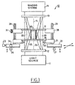
- Figure 1 is a schematic side view of a diffraction grating interferometer provided with the inventive object-fixturing system.
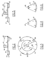
- Figure 2 is a schematic side view of a window platform, positioning fixture, and object arranged according to the invention.
- Figure 3 is a schematic plan view of the window platform, object, and positioning fixture of FIG. 2.
- Figure 4 is a schematic bottom view of the positioning fixture of FIG. 2.
- Figure 5 is a schematic side view, similar to the view of FIG. 2, showing a conical object and a corresponding positioning fixture arranged relative to a window platform.
- Figure 6 is a schematic bottom view of the positioning fixture of FIG. 5.
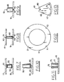
- Figures 7 and 8 are schematic side views of a pair of windows arranged for clamping objects between them in ways similar to the arrangement shown in FIG. 1.
- Figures 9-11 schematically show support windows arranged for holding different objects for measurement.
- Figure 12 schematically shows a window platform having two different fixture-locating regions.
- Figure 13 schematically shows a positioning fixture having a key that fits the two recesses of the window platform of FIG. 12.
- FIG. 1 An object-measuring interferometer 10 of the type used with our fixture system is systematically shown in FIG. 1.
- a source 11 of preferably monochromatic, collimated light is directed through a pair of diffraction gratings 12 and 13 arranged on an optical axis 15 shown as a broken line.
- each diffraction grating 12 and 13 is formed with concentric circular lines that diffract transmitted light into a reference beam 20 and a test beam 25.
- the reference beam 20 is a zero order beam that passes aside of an object 30 to be measured
- the test beam 25 is preferably a first order beam that is incident on a surface of object 30 at a grazing incidence angle.
- Test beam 25 reflects off the surface of object 30 and is recombined with reference beam 20 at diffraction grating 13. This produces an interference pattern that is viewed by imaging system 14 so that the surface of object 30 can be measured.
- Object 30 is supported between gratings 12 and 13 on a window 16 that transmits the reference and test beams.
- Window 16 is supported by window platform 21 that is preferably movable, for reasons explained below.
- Platform 21 includes an adjustable aperture 32 that is preferably an iris device for adjusting the diameter of the light transmitted through grating 12.
- Window platform 21 is mounted on a stage 22 that permits the desired movement.
- Schematically illustrated movement devices 23-27 provide movement in X and Y directions and tilt adjustment of a plane in which the X and Y motions occur.
- Movement controllers 23-27 can be micrometer-type manual devices or motor driven and computer controlled.
- a clamping window 17 is sometimes used to engage an upper portion of object 30. This is important for measuring objects 30 that are unstable or are unable for some reason to stand reliably upright. Clamping can also be used for objects oriented in a horizontal or other non-vertical position. Window 17 is supported on a clamping platform 28 that is adjustable vertically on guide rods 29 and can be held in an elevated position by set screw 31. Many other variations are possible for movement of clamping platform 28. The basic requirement is to elevate platform 28 while changing objects 30, and lower platform 28 so that clamping window 17 engages a positioned object 30 for measurement. The weight of window 17 is normally sufficient for clamping, although other clamping force can be applied. Window 17 also transmits the test and reference beams to upper diffraction grating 13.
- FIGS. 2-4 A fixture 40 for positioning object 30 on window 16 in alignment with optical axis 15 is shown in FIGS. 2-4.
- a circular periphery of window platform 21 forms a reference surface 41 that fixture 40 engages with a surface 42.
- Fixture 40 can be slid on and off window platform 21 to bring its surface 42 into and out of engagement with reference surface 41 and the periphery of window platform 21.
- Fixture 40 also has a positioning surface or edge 43 that engages object 30.
- a cylindrical or conical surface of object 30 can engage positioning surface 43 of fixture 40 along two lines or four points, but many other alternatives are possible.
- Fixture 40 can be a single piece of material, as schematically illustrated, or can be an assembly of several parts. It can also have many shapes and can engage objects with positioning surfaces, edges, or points having different configurations. It can also engage an interferometer reference surface in a variety of ways, including lines, points, and keys. Many different forms can be substituted for the simple circular reference surface 41 illustrated for window platform 21, and the shape adopted for an interferometer reference surface will affect the shape of fixture 40 and its engagement surface 42 that moves into contact with a reference surface.
- Objects 30 can be somewhat barrel shaped or have surfaces of other configurations that depart from cylindrical or conical. Such variations can be accommodated by different shaped positioning surfaces 43 on fixtures 40.
- a single interferometer can have a variety of fixtures 40 of different dimensions and configurations for positioning different shaped objects. An example of this is illustrated in FIGS. 5 and 6 where a fixture 45 has a conical shaped positioning surface 46 for engaging and positioning the correspondingly conical surface of an object 50 supported on window platform 21.
- FIG. 7 schematically shows a clamping arrangement for an object 55 that does not stand stably upright.
- Object 55 has rounded ends so that it needs to be positioned upright as well as aligned with the optical axis of the interferometer.
- a fixture 45 such as illustrated in FIG. 6, can have a positioning surface 46 shaped to engage object 55 and hold it in an accurately upright position on window 16 where object 55 is positioned on supporting pad 56. Then, upper window 17 is lowered into clamping engagement with the upper end of object 55, which is engaged by a clamping pad 57 on the underside of clamping window 17.
- FIG. 8 Another example of an object 60 that benefits from clamping is schematically shown in FIG. 8.
- Object 60 has end projections 61 that are lodged in holes or recesses 62 formed in supporting window 16 and clamping window 17.
- a fixture 40 or 45 can aid in positioning object 60 so that projections 61 fit quickly and reliably into receiving openings 62.
- FIG. 9 schematically shows an object 65 that has end projections 64 but also stands stably upright.
- Objects 65 can be positioned on window 16 by inserting an end projection 64 into a hole or recess 63 in window 16.
- FIGS. 7-9 illustrate the possibility of using different windows in platforms 21 and 28 and giving windows and fixtures different configurations for accommodating differently shaped objects.
- Supporting window 16 can also be provided with a magnet 66 for holding an object 70, and a magnet 66 can be arranged in many ways at or above the upper surface of window 16.
- magnet 66 is mounted on a small universal joint or ball joint 67 that is frictionally stiff enough to hold a position into which it is adjusted. This allows object 70 to be positioned accurately on magnet 66 and adjusted to an upright position by joint 67.
- object 70 can be measured as supported by magnet 66 or can be clamped in place by an upper window 17 such as illustrated in FIGS. 7 and 8.
- a fixture 45 such as illustrated in FIG. 6 can be used for engaging a conical surface of object 70 for such positioning.
- Magnet 66 whether mounted on joint 67 or on the surface of window 16, provides holding power and movement resistance so that fixturing of objects into a measurement position is quick and reliable. Objects supported on a magnet are less likely to be dislodged from a measurement position by withdrawal of a positioning fixture or a finger of an operator.
- FIG. 11 schematically illustrates the fact that an object 75 can have an internal surface 76 to be measured, instead of, or in addition to, an external surface 77.
- the positioning of object 75 on window 16, with the aid of fixture 40, is done in the same way regardless of whether an inside or outside surface is being measured.
- FIGS. 12 and 13 schematically illustrate locating notches or recesses 71 and 72 formed in the reference surface periphery 41 of window platform 21. These are engaged by projections or keys 73 extending from the engagement surface 42 of fixture 40. This allows two positions for fixture 40 on window platform 21, to accommodate right-handed and left-handed operators of the interferometer. Although object positioning might differ slightly between the two positions of fixture 40, if the same position is used repeatedly, objects of the same size will be consistently positioned.
- FIG. 13 also illustrates a magnet 80 arranged on fixture 40 adjacent positioning surface 43 for magnetically engaging an object to be positioned.
- magnet 80 saves an operator from holding an object against fixture positioning surface 43 by finger pressure.
- An object held by magnet 80 against positioning surface 43 can be moved into a measurement position by fixture 40 and then clamped by upper window 70 before fixture 40 is withdrawn.
- magnet 80 can be movable within fixture 40, as indicated by the double-headed arrow, to apply and then withdraw magnetic holding power.
- An object can be positioned while magnet 80 is adjacent positioning surface 43, and then magnet 80 can be withdrawn from positioning surface 43 so that fixture 40 can be removed from the interferometer without moving the positioned object.
- Many other possible uses for magnets can involve window receivers for objects and fixtures for positioning objects.
- a fixture 40 having a positioning surface 43 that fits or is compatible with the objects to be positioned would be selected for use, and the first object would be positioned on window 16. This would be done by moving fixture 40 into engagement with a reference surface while holding the object against positioning surface 43, either magnetically or by finger pressure. If a fixture of proper dimensions has been selected, this should place the object near the center of window platform 21 and near optical axis 15 of interferometer 10. If the object needs to be clamped in position, window clamp 17 would be lowered to engage a top of the object. If the object has end projections or otherwise benefits from a special receiver on window 16, this is preselected by mounting a suitable window on platform 21 and possibly another suitable window on clamping platform 28 in interferometer 10.
- stage 22 is adjusted to align the object with optical axis 15. This can be done by manually moving adjustment devices 23-27 while observing a pattern of fringes produced by imaging system 14. It can also be done by computer control of motor-driven adjustment devices that are responsive to computer analysis of an interferogram formed in imaging system 14. Adjustable aperture 32 may also be set at this time to exclude any unnecessary illumination transmitted through diffraction grating 12.
- the same fixture that was previously used is then redeployed for positioning a second object for a second measurement. Since similar objects in a measurement series have the same nominal size, reuse of the fixture brings the second object accurately to the same position that the first one occupied, without requiring any readjustment of stage 22. The second object is then quickly measured and removed, and the process is repeated until all the objects in the sequence have been measured. Fixture positioning of subsequent objects for measurement proceeds quickly after the first object is brought into adjusted alignment with the optical axis of the interferometer. Repeated use of the same positioning fixture ensures that each subsequent object in a series occupies the same position as the first one.
- any adjustments in window 16 or 17 are predetermined, a proper fixture is selected, the initial object is positioned and properly aligned, and then subsequent objects are accurately brought to the same position by reusing the same fixture.
- interferometer 10 can complete a measurement of a properly positioned object in a few seconds, our fixturing system appreciably speeds up the process of measuring a sequence of objects of the same size. It also does this with simple and inexpensive components that do not interfere with the mechanical or optical operation of the interferometer.
Landscapes
- Physics & Mathematics (AREA)
- General Physics & Mathematics (AREA)
- Instruments For Measurement Of Length By Optical Means (AREA)
- Length Measuring Devices By Optical Means (AREA)
- Length Measuring Devices With Unspecified Measuring Means (AREA)
Claims (11)
- Interferometer (10) mit einem Paar von Beugungsgittern (12, 13), die so angeordnet sind, dass sie Test- und Bezugsstrahlen (25, 20) erzeugen und vereinigen, umfassend eine bewegliche Bühne (22), die zwischen den Beugungsgittern im Weg der Test- und Bezugsstrahlen angeordnet ist; wobei das Interferometer gekennzeichnet ist durch:wobei die Haltevorrichtung eine Positionierungsfläche (43) aufweist, um mit einem Objekt (30) in Eingriff zu gelangen und es in einer Messposition auf der Fensterplattform zu positionieren, wo der Teststrahl auf das Objekt auftrifft; undeine Fensterplattform (21), die auf der beweglichen Bühne montiert ist und ein Fenster (16) aufweist, durch das die Test- und Bezugsstrahlen hindurchgehen;eine Haltevorrichtung (40) mit einer Lokalisierungsfläche (42), die mit einer Bezugsfläche (41) der Fensterplattform in Eingriff bringbar ist;
die Haltevorrichtung vom Interferometer abnehmbar ist, um das Objekt zur Messung einer Oberfläche des Objekts auf der Fensterplattform positioniert zu lassen. - Interferometer nach Anspruch 1, worin die Positionierungsfläche der Haltevorrichtung mit der Objekt-Oberfläche in Eingriff steht, die gemessen wird.
- Interferometer nach Anspruch 1 oder 2, das eine Objektaufnahme umfasst, die auf der Plattform zum Halten des Objekts in einer fixierten Stellung angeordnet ist.
- Interferometer nach einem der Ansprüche 1 bis 3, das eine Klammer (17) zum Eingriff mit einem, dem auf der Fensterplattform aufliegenden Ende des Objekts gegenüberliegenden Ende umfasst.
- Interferometer nach einem der Ansprüche 1 bis 4, worin die Fensterplattform eine einstellbare Öffnung (32) umfasst, um die Größe der Test- und Bezugsstrahlen zu begrenzen.
- Interferometer nach einem der Ansprüche 1 bis 5, worin sich die Bezugsfläche der Fensterplattform unterhalb einer Ebene befindet, auf der das Objekt aufliegt, und sich die Positionierungsfläche der Haltevorrichtung oberhalb der Ebene befindet, auf der das Objekt aufliegt.
- Verfahren zum Befestigen von Objekten in einer Messposition zwischen Beugungsgittern (12, 13), die Test- und Bezugsstrahlen (25, 20) in einem Interferometer (10) erzeugen und vereinigen, wobei das Verfahren umfasst:a. die Verwendung einer Fensterplattform (21) auf einer beweglichen Bühne (22), um ein Objekt (30) zwischen den Beugungsgittern des Interferometers zu tragen;b. die Verwendung einer Haltevorrichtung (40) zum Eingriff mit dem Objekt und der Fensterplattform, um das Objekt in einer Messposition auf einer optischen Achse (15) des Interferometers in einem Weg des Teststrahls zu positionieren;c. das Entfernen und Ersetzen von Objekten der selben Größe durch Positionierung der Objekte mit der Haltevorrichtung; undd. das Bewegen der Haltevorrichtung aus der Eingriffsposition mit jedem Objekt in einer Messposition während der Messung von Oberflächen der Objekte.
- Verfahren nach Anspruch 7, das das Bewegen der Haltevorrichtung und des Objekts, wobei die Haltevorrichtung in die Fensterplattform eingreift und sich das Objekt zur Messposition auf der optischen Achse bewegt, und nachfolgend das anschließende Zurückziehen der Haltevorrichtung vom Interferometer umfasst, um das Objekt in der Messposition zu belassen.
- Verfahren nach Anspruch 7 oder 8, das die Verwendung einer Objektaufnahme auf der Fensterplattform umfasst, um das Objekt in der Messposition aufliegen zu lassen.
- Verfahren nach einem der Ansprüche 7 bis 9, das das Festklemmen des Objekts in der Messposition und das Lösen des Objekts zum Entfernen vom Interferometer umfasst.
- Verfahren nach Anspruch 9, das die Verwendung eines Magneten (66) in der Objektaufnahme umfasst.
Applications Claiming Priority (3)
| Application Number | Priority Date | Filing Date | Title |
|---|---|---|---|
| US634218 | 1996-04-18 | ||
| US08/634,218 US5684594A (en) | 1996-04-18 | 1996-04-18 | Object fixturing in interferometer |
| PCT/US1997/006046 WO1997039309A1 (en) | 1996-04-18 | 1997-04-11 | Object fixturing in interferometer |
Publications (2)
| Publication Number | Publication Date |
|---|---|
| EP0894239A1 EP0894239A1 (de) | 1999-02-03 |
| EP0894239B1 true EP0894239B1 (de) | 2003-06-25 |
Family
ID=24542881
Family Applications (1)
| Application Number | Title | Priority Date | Filing Date |
|---|---|---|---|
| EP97920346A Expired - Lifetime EP0894239B1 (de) | 1996-04-18 | 1997-04-11 | Vorrichtung zur fixierung eines objektes in einem interferometer |
Country Status (6)
| Country | Link |
|---|---|
| US (1) | US5684594A (de) |
| EP (1) | EP0894239B1 (de) |
| JP (1) | JP3296566B2 (de) |
| KR (1) | KR20000005525A (de) |
| DE (1) | DE69723068T2 (de) |
| WO (1) | WO1997039309A1 (de) |
Families Citing this family (4)
| Publication number | Priority date | Publication date | Assignee | Title |
|---|---|---|---|---|
| DE19602445A1 (de) * | 1996-01-24 | 1997-07-31 | Nanopro Luftlager Produktions | Vorrichtung und Verfahren zum Vermessen von zwei einander gegenüberliegenden Oberflächen eines Körpers |
| US5889591A (en) * | 1996-10-17 | 1999-03-30 | Tropel Corporation | Interferometric measurement of toric surfaces at grazing incidence |
| JP3710260B2 (ja) * | 1997-06-23 | 2005-10-26 | キヤノン株式会社 | 光学素子、それを保持する保持治具及びその光学素子を用いた撮像装置 |
| KR101327217B1 (ko) * | 2012-12-20 | 2013-11-20 | 주식회사 서울금속 | 원통형 제품의 외주면 검사장치 |
Family Cites Families (5)
| Publication number | Priority date | Publication date | Assignee | Title |
|---|---|---|---|---|
| DE106769C (de) * | ||||
| US3436153A (en) | 1965-10-05 | 1969-04-01 | Atomic Energy Commission | Object measuring by interferometry |
| JPS62177421A (ja) * | 1986-01-31 | 1987-08-04 | Fuji Photo Optical Co Ltd | 斜入射干渉計装置 |
| US4844614A (en) * | 1987-09-01 | 1989-07-04 | Nicolet Instrument Corporation | Interchangeable beam splitting holder and compartment therefor |
| US5530547A (en) * | 1994-08-04 | 1996-06-25 | Arnold; Steven M. | Method and apparatus for aligning optical elements and testing aspheric optical components |
-
1996
- 1996-04-18 US US08/634,218 patent/US5684594A/en not_active Expired - Fee Related
-
1997
- 1997-04-11 EP EP97920346A patent/EP0894239B1/de not_active Expired - Lifetime
- 1997-04-11 WO PCT/US1997/006046 patent/WO1997039309A1/en not_active Ceased
- 1997-04-11 JP JP53723597A patent/JP3296566B2/ja not_active Expired - Fee Related
- 1997-04-11 KR KR1019980708320A patent/KR20000005525A/ko not_active Withdrawn
- 1997-04-11 DE DE69723068T patent/DE69723068T2/de not_active Expired - Fee Related
Also Published As
| Publication number | Publication date |
|---|---|
| JP3296566B2 (ja) | 2002-07-02 |
| EP0894239A1 (de) | 1999-02-03 |
| DE69723068T2 (de) | 2004-04-08 |
| DE69723068D1 (de) | 2003-07-31 |
| KR20000005525A (ko) | 2000-01-25 |
| JP2002505735A (ja) | 2002-02-19 |
| US5684594A (en) | 1997-11-04 |
| WO1997039309A1 (en) | 1997-10-23 |
Similar Documents
| Publication | Publication Date | Title |
|---|---|---|
| US5026033A (en) | Universal system for the support and positioning of a workpiece | |
| US5150041A (en) | Optically alignable printed circuit board test fixture apparatus and associated methods | |
| US7036810B2 (en) | Modular tooling apparatus with tapered locater system | |
| EP0806627B1 (de) | Anordnung zum Kontrollieren der Dimensionen eines mechanischen Stucks und Verfahren zum Betrieb der Anordnung | |
| USRE37695E1 (en) | Measuring device for measuring workpieces | |
| EP0894239B1 (de) | Vorrichtung zur fixierung eines objektes in einem interferometer | |
| JP6936161B2 (ja) | 位置決めピンの位置調整に使用される治具セット | |
| US3319339A (en) | Multi-height comparator and gauge | |
| US5313714A (en) | Instrument for measuring dimensions of a can seam portion | |
| JPH063219A (ja) | 干渉計装置 | |
| US3021603A (en) | Gauging device | |
| CN117537732A (zh) | 一种方形钢构件挠度激光测量工装及检测方法 | |
| US3285127A (en) | Magnetically attached microscope accessory for supporting comparison objects | |
| US4599801A (en) | Portable gage instrument for use in performing precision multiple dimension measurements | |
| US4381671A (en) | Tire mounting system | |
| KR20080049166A (ko) | 시편 제조 장치 및 방법 | |
| CA2030028A1 (en) | Universal system for the support and positioning of a workpiece | |
| US6765734B1 (en) | Adjustable sample holder for optical equipment | |
| JP2000314685A (ja) | タイヤ試験方法及び装置 | |
| CN223050831U (zh) | 一种便于固定的镜片测试机构 | |
| CN220230329U (zh) | 一种指示表检定仪 | |
| CN112326212B (zh) | 喷嘴吹气波形测试装置 | |
| JPH0566512U (ja) | 縦型真直度測定装置 | |
| JP2531691Y2 (ja) | 光学測定器の光軸合せ装置 | |
| JPH057532Y2 (de) |
Legal Events
| Date | Code | Title | Description |
|---|---|---|---|
| PUAI | Public reference made under article 153(3) epc to a published international application that has entered the european phase |
Free format text: ORIGINAL CODE: 0009012 |
|
| 17P | Request for examination filed |
Effective date: 19981109 |
|
| AK | Designated contracting states |
Kind code of ref document: A1 Designated state(s): AT BE CH DE FR GB IE IT LI SE |
|
| GRAG | Despatch of communication of intention to grant |
Free format text: ORIGINAL CODE: EPIDOS AGRA |
|
| 17Q | First examination report despatched |
Effective date: 20020517 |
|
| GRAG | Despatch of communication of intention to grant |
Free format text: ORIGINAL CODE: EPIDOS AGRA |
|
| GRAG | Despatch of communication of intention to grant |
Free format text: ORIGINAL CODE: EPIDOS AGRA |
|
| GRAH | Despatch of communication of intention to grant a patent |
Free format text: ORIGINAL CODE: EPIDOS IGRA |
|
| GRAH | Despatch of communication of intention to grant a patent |
Free format text: ORIGINAL CODE: EPIDOS IGRA |
|
| RBV | Designated contracting states (corrected) |
Designated state(s): DE FR GB |
|
| GRAA | (expected) grant |
Free format text: ORIGINAL CODE: 0009210 |
|
| AK | Designated contracting states |
Designated state(s): DE FR GB |
|
| REG | Reference to a national code |
Ref country code: GB Ref legal event code: FG4D |
|
| REG | Reference to a national code |
Ref country code: IE Ref legal event code: FG4D |
|
| REF | Corresponds to: |
Ref document number: 69723068 Country of ref document: DE Date of ref document: 20030731 Kind code of ref document: P |
|
| ET | Fr: translation filed | ||
| PG25 | Lapsed in a contracting state [announced via postgrant information from national office to epo] |
Ref country code: GB Free format text: LAPSE BECAUSE OF NON-PAYMENT OF DUE FEES Effective date: 20040411 |
|
| PLBE | No opposition filed within time limit |
Free format text: ORIGINAL CODE: 0009261 |
|
| STAA | Information on the status of an ep patent application or granted ep patent |
Free format text: STATUS: NO OPPOSITION FILED WITHIN TIME LIMIT |
|
| 26N | No opposition filed |
Effective date: 20040326 |
|
| GBPC | Gb: european patent ceased through non-payment of renewal fee |
Effective date: 20040411 |
|
| PG25 | Lapsed in a contracting state [announced via postgrant information from national office to epo] |
Ref country code: FR Free format text: LAPSE BECAUSE OF NON-PAYMENT OF DUE FEES Effective date: 20041231 |
|
| REG | Reference to a national code |
Ref country code: IE Ref legal event code: MM4A |
|
| REG | Reference to a national code |
Ref country code: FR Ref legal event code: ST |
|
| PGFP | Annual fee paid to national office [announced via postgrant information from national office to epo] |
Ref country code: DE Payment date: 20050531 Year of fee payment: 9 |
|
| PG25 | Lapsed in a contracting state [announced via postgrant information from national office to epo] |
Ref country code: DE Free format text: LAPSE BECAUSE OF NON-PAYMENT OF DUE FEES Effective date: 20061101 |