EP0894209B1 - Worm and gear drive - Google Patents
Worm and gear drive Download PDFInfo
- Publication number
- EP0894209B1 EP0894209B1 EP97921075A EP97921075A EP0894209B1 EP 0894209 B1 EP0894209 B1 EP 0894209B1 EP 97921075 A EP97921075 A EP 97921075A EP 97921075 A EP97921075 A EP 97921075A EP 0894209 B1 EP0894209 B1 EP 0894209B1
- Authority
- EP
- European Patent Office
- Prior art keywords
- gear
- drive
- worm shaft
- tooth
- drive gear
- Prior art date
- Legal status (The legal status is an assumption and is not a legal conclusion. Google has not performed a legal analysis and makes no representation as to the accuracy of the status listed.)
- Expired - Lifetime
Links
- 238000000034 method Methods 0.000 claims description 37
- 238000004519 manufacturing process Methods 0.000 claims description 14
- 239000011295 pitch Substances 0.000 claims description 8
- 238000005096 rolling process Methods 0.000 claims 3
- 230000008878 coupling Effects 0.000 claims 2
- 238000010168 coupling process Methods 0.000 claims 2
- 238000005859 coupling reaction Methods 0.000 claims 2
- 230000013011 mating Effects 0.000 description 8
- 239000000463 material Substances 0.000 description 4
- 229910000831 Steel Inorganic materials 0.000 description 2
- 230000004075 alteration Effects 0.000 description 2
- 239000002184 metal Substances 0.000 description 2
- 239000010959 steel Substances 0.000 description 2
- 230000000295 complement effect Effects 0.000 description 1
- 230000002950 deficient Effects 0.000 description 1
- 230000000694 effects Effects 0.000 description 1
- 238000005516 engineering process Methods 0.000 description 1
- 238000003754 machining Methods 0.000 description 1
Images


Classifications
-
- E—FIXED CONSTRUCTIONS
- E05—LOCKS; KEYS; WINDOW OR DOOR FITTINGS; SAFES
- E05F—DEVICES FOR MOVING WINGS INTO OPEN OR CLOSED POSITION; CHECKS FOR WINGS; WING FITTINGS NOT OTHERWISE PROVIDED FOR, CONCERNED WITH THE FUNCTIONING OF THE WING
- E05F15/00—Power-operated mechanisms for wings
- E05F15/60—Power-operated mechanisms for wings using electrical actuators
- E05F15/603—Power-operated mechanisms for wings using electrical actuators using rotary electromotors
- E05F15/665—Power-operated mechanisms for wings using electrical actuators using rotary electromotors for vertically-sliding wings
- E05F15/689—Power-operated mechanisms for wings using electrical actuators using rotary electromotors for vertically-sliding wings specially adapted for vehicle windows
- E05F15/697—Motor units therefor, e.g. geared motors
-
- F—MECHANICAL ENGINEERING; LIGHTING; HEATING; WEAPONS; BLASTING
- F16—ENGINEERING ELEMENTS AND UNITS; GENERAL MEASURES FOR PRODUCING AND MAINTAINING EFFECTIVE FUNCTIONING OF MACHINES OR INSTALLATIONS; THERMAL INSULATION IN GENERAL
- F16H—GEARING
- F16H1/00—Toothed gearings for conveying rotary motion
- F16H1/02—Toothed gearings for conveying rotary motion without gears having orbital motion
- F16H1/04—Toothed gearings for conveying rotary motion without gears having orbital motion involving only two intermeshing members
- F16H1/12—Toothed gearings for conveying rotary motion without gears having orbital motion involving only two intermeshing members with non-parallel axes
- F16H1/16—Toothed gearings for conveying rotary motion without gears having orbital motion involving only two intermeshing members with non-parallel axes comprising worm and worm-wheel
-
- F—MECHANICAL ENGINEERING; LIGHTING; HEATING; WEAPONS; BLASTING
- F16—ENGINEERING ELEMENTS AND UNITS; GENERAL MEASURES FOR PRODUCING AND MAINTAINING EFFECTIVE FUNCTIONING OF MACHINES OR INSTALLATIONS; THERMAL INSULATION IN GENERAL
- F16H—GEARING
- F16H55/00—Elements with teeth or friction surfaces for conveying motion; Worms, pulleys or sheaves for gearing mechanisms
- F16H55/02—Toothed members; Worms
- F16H55/22—Toothed members; Worms for transmissions with crossing shafts, especially worms, worm-gears
-
- E—FIXED CONSTRUCTIONS
- E05—LOCKS; KEYS; WINDOW OR DOOR FITTINGS; SAFES
- E05Y—INDEXING SCHEME ASSOCIATED WITH SUBCLASSES E05D AND E05F, RELATING TO CONSTRUCTION ELEMENTS, ELECTRIC CONTROL, POWER SUPPLY, POWER SIGNAL OR TRANSMISSION, USER INTERFACES, MOUNTING OR COUPLING, DETAILS, ACCESSORIES, AUXILIARY OPERATIONS NOT OTHERWISE PROVIDED FOR, APPLICATION THEREOF
- E05Y2900/00—Application of doors, windows, wings or fittings thereof
- E05Y2900/50—Application of doors, windows, wings or fittings thereof for vehicles
- E05Y2900/53—Type of wing
- E05Y2900/55—Windows
-
- Y—GENERAL TAGGING OF NEW TECHNOLOGICAL DEVELOPMENTS; GENERAL TAGGING OF CROSS-SECTIONAL TECHNOLOGIES SPANNING OVER SEVERAL SECTIONS OF THE IPC; TECHNICAL SUBJECTS COVERED BY FORMER USPC CROSS-REFERENCE ART COLLECTIONS [XRACs] AND DIGESTS
- Y10—TECHNICAL SUBJECTS COVERED BY FORMER USPC
- Y10T—TECHNICAL SUBJECTS COVERED BY FORMER US CLASSIFICATION
- Y10T74/00—Machine element or mechanism
- Y10T74/18—Mechanical movements
- Y10T74/18568—Reciprocating or oscillating to or from alternating rotary
- Y10T74/18792—Reciprocating or oscillating to or from alternating rotary including worm
-
- Y—GENERAL TAGGING OF NEW TECHNOLOGICAL DEVELOPMENTS; GENERAL TAGGING OF CROSS-SECTIONAL TECHNOLOGIES SPANNING OVER SEVERAL SECTIONS OF THE IPC; TECHNICAL SUBJECTS COVERED BY FORMER USPC CROSS-REFERENCE ART COLLECTIONS [XRACs] AND DIGESTS
- Y10—TECHNICAL SUBJECTS COVERED BY FORMER USPC
- Y10T—TECHNICAL SUBJECTS COVERED BY FORMER US CLASSIFICATION
- Y10T74/00—Machine element or mechanism
- Y10T74/19—Gearing
- Y10T74/19642—Directly cooperating gears
- Y10T74/19698—Spiral
- Y10T74/19828—Worm
-
- Y—GENERAL TAGGING OF NEW TECHNOLOGICAL DEVELOPMENTS; GENERAL TAGGING OF CROSS-SECTIONAL TECHNOLOGIES SPANNING OVER SEVERAL SECTIONS OF THE IPC; TECHNICAL SUBJECTS COVERED BY FORMER USPC CROSS-REFERENCE ART COLLECTIONS [XRACs] AND DIGESTS
- Y10—TECHNICAL SUBJECTS COVERED BY FORMER USPC
- Y10T—TECHNICAL SUBJECTS COVERED BY FORMER US CLASSIFICATION
- Y10T74/00—Machine element or mechanism
- Y10T74/19—Gearing
- Y10T74/19949—Teeth
- Y10T74/19953—Worm and helical
Definitions
- This invention relates to a vehicle window drive system and method and, more particularly, to a multi-tooth contact drive gear system and method used in a vehicle window environment which may be manufactured using roll manufacturing techniques.
- worm gear which was rotatably driven by a drive motor and which, in turn, drove a driven gear.
- the worm gear comprised a torque capacity which was much less than, for example, an enveloped gear. This was due primarily to the fact that the worm gear had a primary or single contact tooth which contacted a mating tooth of the driven gear.
- Such a worm gear drive is disclosed in the U.S. patent 3,386,305. It comprises a worm gear meshing with a worm. The contact path between the teeth of the worm gear and the worm is situated along a cylindrical surface which is coaxial with the worm gear.
- the U.S. patent 5,040,430 discloses a window-actuated drive comprising a worm gear meshing with a worm, only one pair of teeth being in engagement at a given time.
- this invention comprises a system for driving a component comprising the features of claim 1
- this invention comprises a method for increasing drive torque of a roll-manufactured worm drive gear layout having the features of claim 10.
- this invention comprises a method for generating a gear comprising the steps of claim 15.
- a system 10 for driving a component 12, such as a window (not shown) in a door (not shown) of a vehicle (not shown).
- the system 10 comprises a drive motor 14 which is coupled to a drive gear 16.
- the drive gear 16 is a worm gear having a single helical thread 17, and the drive motor 14 may be Part No. 16631020 available from the assignee of the present invention.
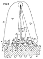
- thread 17 of gear 16 defines a plurality of teeth in cross section, such as teeth 16a-16f. It should be appreciated, however, that the gear 16 may actually comprise more than one single helical thread (i.e., multiple individual threads or several separate threads).
- the drive motor 14 (Fig. 1) rotatably drives drive or worm gear 16 at approximately 3000 revolutions per minute in response to actuation of a switch (not shown), such as a power window switch in the vehicle.
- drive gear 16 is operably associated with and coupled to driven gear 18 which, in turn, is coupled to component 12 via suitable linkage 20.
- linkage 20 comprises a drive train of gears, lever arms and the like, as are conventionally known.
- the plurality of drive teeth 16a-16f each comprise an associated imaginary center line, such as imaginary center lines 24, 26, 28, 30, 32 and 34.
- the center lines 24-34 for teeth 16a-16f are substantially parallel to each other and substantially perpendicular to an axis of shaft 22.
- center lines 24-34 are also substantially parallel to a radial line 36 which emanates from gear 18 and which is perpendicular to the axis of shaft 22.
- this design facilitates manufacturing drive gear 16 using conventional roll manufacturing techniques. This, in turn, facilitates producing drive gears 16 on a mass-production basis.
- teeth 16a-16f engage mating teeth, such as teeth 18c-18f, to rotatably drive gear 18 in response to driven rotation of shaft 22 by motor 14 (Fig. 1).
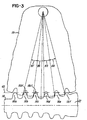
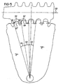
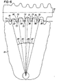
- teeth 16a-16f engage mating teeth 18c-18f at a plurality of contact points 33, 35, 37 and 39. These contact points lie in an arbitrary arrangement 40 which is typically not concentric about the axis of gear 18.
- a pitch distance between adjacent contact points, such as contact points 33-35 and 37-39 may vary, while angles ⁇ 1 , ⁇ 2 and ⁇ 3 remain substantially equal, as described later herein.
- these pitches or distances between points 24, 26, 28, 30, 32 and 34 may vary continuously depending on the tooth position of drive teeth 16a-16f.
- the point of contact of the various contact points 33, 35, 37 and 39 varies on each tooth face.
- the contact point 33 on a face 18c1 of tooth 18c, contact point 35 on a face 18d1 of tooth 18d, contact point 37 on a face 18e1 of tooth 18e and contact point 38 on a face 18f1 of tooth 18f each lie at different points on their respective faces. This facilitates distributing wear across the faces of the plurality of teeth of driven gear 18.
- this invention facilitates increasing the torque capacity of gear 16 by providing three or more contact points, rather than a single or two tooth contact point for conventional worm gear. It has been found that a drive gear 16 which comprises features of this invention may achieve a torque capacity which is similar to that of an enveloped worm gear which required special machining and could not be mass produced using conventional roll manufacturing techniques.
- the drive gear 16 may be provided with teeth which define a profile which is generally cylindrical or straight relative to line 43.
- the plurality of teeth 16a-16f could be manufactured such that the distance between tips, such as tip 16b1 on tooth 16b and tip 16c1 on tooth 16c, cooperate to define a profile which is stepped relative to axis of shaft 22.
- the plurality of teeth 16a-16f could be curved (not shown) to complement the shape of the driven gear 18, such that driven gear 18 becomes partially enveloped.
- the apparatus and method of the present invention tolerates variations in the distance between the tips, such as tips 16b1 and 16c1 of teeth 16b and 16c, respectively, and the axis of shaft 22.
- the gear 16 may be designed such that tooth heights vary.
- the features of this invention and of gear 16 may be utilized with a mating or driven gear 18 which is helical, spur or any suitable gear having involute teeth.
- the method begins by specifying a plurality of requirements for the gear to be designed. In particular, it is necessary to define a speed ratio, a center distance between a nominal center line of drive gear 16 and center line of worm gear 18. This is particularly advantageous when the mating gear 18 is molded from plastic material and the worm is made of metal or steel material, and a maximum output torque is to be achieved by the drive gear 16.
- a gear module M is set equal to (Dg/Ng), and a gear circular pitch (“Pc”) is defined as ⁇ x M.
- "x" is a material strength balance factor used, for example, when balancing the strength of the drive gear 16 relative to the driven gear 18. This is particularly important where the mating gear 18 is made of plastic material and the drive gear 16 is made of steel or metal.
- the trial gear tooth thickness and trial worm tooth thickness are determined using conventional formuli for a standard straight gear or worm layout.
- a straight worm layout is illustrated in Fig. 4.
- the profile of the gear 16 to be manufactured comprise a curved or arbitrary shape
- the method for increasing the drive torque of a roll manufactured drive gear is achieved by this invention by generating a drive gear (not shown) in accordance with the aforementioned drive gear layout.
- a drive shaft may be manufactured using conventional roll manufacturing techniques.
- the drive gear 16 (Fig. 2) and its associated plurality of drive teeth 16b-16f may then be positioned in an operative relationship with a plurality of driven teeth on the driven gear 18 which may be a spur gear or a helical gear.
- the gear 16 is used in the system 10 in a vehicle environment where in response to a switch (not shown) the drive motor 14 (Fig. 1) is energized by a controller (not shown).
- the drive motor 14 rotatably drives drive gear 16 which, in turn, drives driven gear 18.
- drive gear 18 drives component 12 via suitable linkage 20. This causes the component 12, like a window in an automobile (not shown), to move in a desired direction, such as from an open position to a closed position or vice versa.
- this system and method provide means for using roll manufacturing technology to generate a multi-tooth contact and variable contact gear, such as a worm gear.
Landscapes
- Engineering & Computer Science (AREA)
- General Engineering & Computer Science (AREA)
- Mechanical Engineering (AREA)
- Gear Transmission (AREA)
- Gears, Cams (AREA)
Description
Claims (22)
- A system (10) for driving a component comprising:characterized in that at least two of said plurality of driven teeth (60, 62, 64, 66, 67, 68, 69, 82, 84, 86, 88, 90) contact any one of said plurality of cross sections of at least a drive tooth (42, 44, 45, 47, 49, 51, 61, 63, 71, 73, 75, 77, 79) at a plurality of contact points (33, 35, 37, 50, 52) in an arrangement. (40) which is not concentric about the axis of the driven gear (18) such that wear is distributed across a face of each of said plurality of cross sections of at least a drive tooth (42, 44, 45, 47, 49, 51, 61, 63, 71, 73, 75, 77, 79).a drive motor (14);a coupler for coupling said component to said drive motor (14) such that when said drive motor (14) is energized, said component is driven to a desired position;said coupler comprising:a gear train having a worm shaft drive gear (16) coupled to said drive motor (14) and a driven gear (18); anda linkage (20) for coupling said drive gear to said component;said worm shaft drive gear (16) comprises a plurality of cross sections of at least a drive tooth, said plurality of cross sections of at least a drive tooth (42, 44, 45, 47, 49, 51, 61, 63, 71, 73, 75, 77, 79) being substantially parallel to one another;said driven gear (18) comprises a plurality of driven teeth (60, 62, 64, 66, 67, 68, 69, 82, 84, 86, 88, 90) in cross-section,
- The system as recited in claim 1, characterized in that said worm gear drive shaft (16) is manufactured by rolling a drive shaft.
- The system claim 1 or 2, characterized in that said plurality of cross sections of at least a drive tooth (42, 44, 45, 47, 49, 51, 61, 63, 71, 73, 75, 77, 79) each comprise a center line (24, 2, 28, 30, 32) which is substantially perpendicular to an axis (54, 55, 91) of said drive gear.
- The system of one of the preceding claims, characterized in that said plurality of cross sections of at least a drive tooth (42, 44, 45, 47, 49, 51, 61, 63, 71, 73, 75, 77, 79) define a plurality of pitches, at least two, preferably all of said plurality of pitches not being equal.
- The system of one of the preceding claims, characterized in that said driven gear (18) is a spur gear or a helical gear or defies a profile which is stepped.
- The system of one of the preceding claims, characterized in that said worm shaft drive gear (16) comprises a cylindrical, curved or stepped gear.
- The system of one of the preceding claims, characterized in that at least two of said plurality of cross sections of at least a drive tooth (42, 44, 45, 47, 49, 51, 61, 63, 71, 73, 75, 77, 79) contact any one of a plurality of driven teeth (60, 62, 64, 66, 67, 68, 69, 82, 84, 86, 88, 90) at a plurality of contact points (33, 35, 37, 50, 52), said plurality of contact points (33, 35, 37, 50, 52) lying non-equidistance from an axis of said driven gear (18).
- The system of one of the preceding claims, characterized in that said worm shaft drive gear (16) is a worm gear.
- The system of one of the preceding claims, characterized in that said component is a vehicle window.
- A method for increasing drive torque of a roll-manufactured worm shaft drive gear (16) comprising the steps of:determining a driven gear layout;generating a drive gear layout using said driven gear layout;rolling a plurality of cross sections of at least a drive tooth (42, 44, 45, 47, 49, 51, 61, 63, 71, 73, 75, 77, 79) on a drive shaft using said drive gear layout;said plurality of cross sections of at least a drive tooth (42, 44, 45, 47, 49, 51, 61, 63, 71, 73, 75, 77, 79) being substantially parallel to each other;situating said plurality of cross sections of at least a drive tooth (42, 44, 45, 47, 49, 51, 61, 63, 71, 73, 75, 77, 79) in operative relationship with a plurality of driven teeth (60, 62, 64, 66, 67, 68, 69, 82, 84, 86, 88, 90) on a driven gear (18) such that a plurality of cross sections of at least a drive tooth (42, 44, 45, 47, 49, 51, 61, 63, 71, 73, 75, 77, 79) engage a plurality of driven teeth (60, 62, 64, 66, 67, 68, 69, 82, 84, 86, 88, 90) at different contact points (33, 35, 37, 50, 52), in an arrangement (40) which is not concentric about the axis of the driven gear (18).
- The method of claim 10, characterized in the further step of rolling said plurality of cross sections of at least a drive tooth (42, 44, 45, 47, 49, 51, 61, 63, 71, 73, 75, 77, 79) such that they are substantially perpendicular to an axis (54, 55, 91) of said worm shaft drive gear (16).
- The method of claim 10 or 11, characterized in the further step of generating a drive gear layout comprising a plurality of cross sections of at least a drive tooth (42, 44, 45, 47, 49, 51, 61, 63, 71, 73, 75, 77, 79) at least two of which contact any one of a plurality of driven (60, 62, 64, 66, 67, 68, 69, 82, 84, 86, 88, 90) teeth at a plurality of contact points, said plurality of contact points (33, 35, 37, 50, 52) lying non-equidistance from an axis of said driven gear (18).
- The method one of claims 10 to 12, characterized in the further step of generating a drive gear layout defining a worm shaft drive gear (16) comprising a profile of said plurality of cross sections of at least a drive tooth (42, 44, 45, 47, 49, 51, 61, 63, 71, 73, 75, 77, 79) which is substantially cylindrical, curved or stepped.
- The method of one of claims 10 to 13, characterized in that the further step of generating a drive gear layout comprising a plurality of cross sections of at least a drive tooth (42, 44, 45, 47, 49, 51, 61, 63, 71, 73, 75, 77, 79), at least two of said plurality of cross sections of at least a drive tooth (42, 44, 45, 47, 49, 51, 61, 63, 71, 73, 75, 77, 79) having different heights.
- A method for generating a gear comprising the steps of:(a) specifying a plurality of requirements for a worm shaft drive gear (16);(b) determining a trial tooth thickness of said worm shaft drive gear (16);(c) determining a trial shaft thickness of said worm shaft drive gear (16);(d) establishing a standard straight layout of said worm shaft drive gear (16) comprising a plurality of layout sections of at least a drive tooth (42, 44, 45, 47, 49, 51, 61, 63, 71, 73, 75, 77, 79) using said plurality of requirements specified in step (a), said trial tooth thickness of said worm shaft drive gear (16) determined in step (b), and said trial shaft thickness of said worm shaft drive gear (16). determined in step (c);(e) altering said straight layout of said worm shaft drive gear (16) to provide a modified layout of said worm shaft drive gear (16) having at least two of said plurality of layout sections of at least a drive tooth (42, 44, 45, 47, 49, 51, 61, 63, 71, 73, 75, 77, 79) contacting any one of a plurality of driven teeth (60, 62, 64, 66, 67, 68, 69, 82, 84, 86, 88, 90) of a driven gear (18) at different contact points (33, 35, 37, 50, 52) on said driven teeth (60, 62, 64, 66, 67, 68, 69, 82, 84, 86, 88, 90), in an arrangement (40) which is not concentric about the axis of the driven gear (18).
- The method of claim 15, characterized in the further step of adjusting either said trial tooth thickness of said worm shaft drive gear (16) or said trial shaft thickness of said worm shaft drive gear (16) to achieve said step (e).
- The method of one of claims 15 or 16, characterized in the further step of altering said straight layout of said worm shaft drive gear (16) such that at least four of said plurality of layout sections of at least a drive tooth (42, 44, 45, 47, 49, 51, 61, 63, 71, 73, 75, 77, 79) of said worm shaft drive gear (16) contact at least four of said plurality of driven teeth (60, 62, 64, 66, 67, 68, 69, 82, 84, 86, 88, 90).
- The method of one of claims 15 to 17, characterized in the further step of specifying a speed ratio, a center distance or a maximum output torque.
- The method of one of claims 15 to 18, characterized in the further step of specifying a number of worm starts, a number of sections of at least a drive tooth (42, 44, 45, 47, 49, 51, 61, 63, 71, 73, 75, 77, 79), a trial gear pitch diameter, a gear module or a gear circular pitch.
- The method of one of claims 15 to 19, characterized in the further step of altering said modified layout of said worm shaft drive gear (16) such that said worm shaft drive gear (16) comprises a profile which is cylindrical, stepped or curved in cross section.
- The method of one of claims 15 to 20, characterized in the further step of causing said modified layout of said worm shaft drive gear (16) to comprise a plurality of modified sections of at least a drive tooth (42, 44, 45, 47, 49, 51, 61, 63, 71, 73, 75, 77, 79) which are substantially parallel.
- The method of one of claims 15 to 21, characterized in the further step of using said modified layout of said worm shaft drive gear (16) to roll manufacture said worm shaft drive gear (16).
Applications Claiming Priority (3)
| Application Number | Priority Date | Filing Date | Title |
|---|---|---|---|
| US620853 | 1990-12-03 | ||
| US08/620,853 US5829305A (en) | 1996-03-18 | 1996-03-18 | Vehicle window drive system and method |
| PCT/US1997/004309 WO1997039258A1 (en) | 1996-03-18 | 1997-03-17 | Worm and gear drive |
Publications (2)
| Publication Number | Publication Date |
|---|---|
| EP0894209A1 EP0894209A1 (en) | 1999-02-03 |
| EP0894209B1 true EP0894209B1 (en) | 2003-06-11 |
Family
ID=24487692
Family Applications (1)
| Application Number | Title | Priority Date | Filing Date |
|---|---|---|---|
| EP97921075A Expired - Lifetime EP0894209B1 (en) | 1996-03-18 | 1997-03-17 | Worm and gear drive |
Country Status (4)
| Country | Link |
|---|---|
| US (2) | US5829305A (en) |
| EP (1) | EP0894209B1 (en) |
| DE (1) | DE69722784T2 (en) |
| WO (1) | WO1997039258A1 (en) |
Families Citing this family (12)
| Publication number | Priority date | Publication date | Assignee | Title |
|---|---|---|---|---|
| DE19811976A1 (en) * | 1998-03-19 | 1999-09-23 | Mannesmann Vdo Ag | Drive unit controlling side window of vehicle more quietly |
| AU8099598A (en) * | 1998-06-29 | 2000-01-17 | Tianjin Everbest Gear Co., Ltd. | Worm with modified threads |
| US6247376B1 (en) * | 1999-07-13 | 2001-06-19 | Valeo Electrical Systems, Inc. | Rollable enveloped worm with two curve profile |
| DE10034410A1 (en) * | 2000-07-14 | 2002-01-24 | Bosch Gmbh Robert | Method for producing a shaft and device comprising such a shaft |
| US6915673B2 (en) * | 2001-06-21 | 2005-07-12 | Nissei Co., Ltd. | Method of rolling worm gear and the worm gear |
| US7798033B2 (en) * | 2002-11-14 | 2010-09-21 | Ims Gear Gmbh | Power-assisted steering having a gear mechanism |
| US20050115071A1 (en) * | 2003-12-02 | 2005-06-02 | Yakov Fleytman | Manufacturing for face gears |
| US20050274216A1 (en) * | 2004-05-27 | 2005-12-15 | Yakov Fleytman | Enveloping speed reducer |
| US20060090340A1 (en) * | 2004-11-03 | 2006-05-04 | Yakov Fleytman | Method of generation of face enveloping gears |
| ATE546606T1 (en) * | 2006-01-25 | 2012-03-15 | Vkr Holding As | CHAIN PUSH DRIVE FOR WINDOWS |
| US7536927B2 (en) * | 2006-06-05 | 2009-05-26 | Brose Fahrzeugteile GmbH & Co. Kommanditgesellschaft, Würzburg | Window lift drive for raising and lowering windows in a vehicle door |
| BR112014013577A2 (en) * | 2011-12-06 | 2017-06-13 | Honda Motor Co Ltd | spiral gear mechanism |
Family Cites Families (79)
| Publication number | Priority date | Publication date | Assignee | Title |
|---|---|---|---|---|
| US34667A (en) * | 1862-03-18 | Washing-machine | ||
| US1320372A (en) * | 1919-11-04 | William emil bock | ||
| US1694028A (en) * | 1928-12-04 | wildhaber | ||
| US1683163A (en) * | 1925-06-27 | 1928-09-04 | Cone Gearing Corp | Precision worm gearing |
| US1797461A (en) * | 1928-05-04 | 1931-03-24 | Wildhaber Ernest | Method of forming gears |
| US1876795A (en) * | 1930-04-28 | 1932-09-13 | Trbojevich Nikola | Steering gear |
| US1948795A (en) * | 1930-10-16 | 1934-02-27 | Brown David & Sons Ltd | Worm gearing |
| US1973185A (en) * | 1931-08-14 | 1934-09-11 | Trbojevich Nikola | Gear and gear tooth |
| US1966358A (en) * | 1933-10-04 | 1934-07-10 | John J Robak | Worm gearing |
| US2338367A (en) * | 1943-02-27 | 1944-01-04 | Trbojevich Nikola | Worm gearing |
| US2885903A (en) * | 1956-09-08 | 1959-05-12 | Zahnschneidemaschinenfab Modul | Worm wheel toothing |
| US3045557A (en) * | 1958-12-01 | 1962-07-24 | Yamamoto Akira | Method of cutting cooperating worms and worm wheels |
| US2975649A (en) * | 1959-05-18 | 1961-03-21 | Beaver Prec Products Inc | Ball screw assembly with internal ball return |
| US3068713A (en) * | 1959-10-08 | 1962-12-18 | Nat Broach & Mach | Nut and screw drive device of the recirculating ball type |
| US3068714A (en) * | 1959-10-08 | 1962-12-18 | Nat Broach & Mach | Nut and screw drive device of the recirculating ball type |
| US3302477A (en) * | 1964-11-23 | 1967-02-07 | Gen Motors Corp | Nut and screw assembly |
| US3333484A (en) * | 1965-08-27 | 1967-08-01 | Farrel Corp | Drive mechanism with recirculating ball bearing connection |
| US3386305A (en) * | 1966-04-28 | 1968-06-04 | Wildhaber Ernest | Worm gearing |
| US3477125A (en) * | 1967-07-20 | 1969-11-11 | Robbins & Myers | Method of making a double insulated armature |
| US3476966A (en) * | 1967-11-14 | 1969-11-04 | Gen Electric | Retaining ring locking structure |
| US3489938A (en) * | 1969-01-13 | 1970-01-13 | Kinzo Nakamura | Coil retainer for an iron core of rotary machines of the laminated iron core type |
| DE2103537C2 (en) * | 1971-01-15 | 1972-07-20 | Lindner H Gmbh | CYLINDER SCREW DRIVE |
| JPS4954801A (en) * | 1972-09-27 | 1974-05-28 | ||
| DE2249729A1 (en) * | 1972-10-11 | 1974-04-25 | Binder Magnete | STEPPER MOTOR |
| US3894256A (en) * | 1973-07-26 | 1975-07-08 | Bowmar Instrument Corp | Bearing assembly for dynamoelectric machine |
| FR2249577A5 (en) * | 1973-10-30 | 1975-05-23 | Tech Integrale | |
| US4031610A (en) * | 1974-04-30 | 1977-06-28 | Airborne Mfg. Co. | Method of assembly of dynamoelectric machines |
| US4025840A (en) * | 1975-04-09 | 1977-05-24 | General Electric Company | Permanent magnet generator with output power adjustment by means of magnetic shims |
| US4037485A (en) * | 1975-12-18 | 1977-07-26 | The Goodyear Tire & Rubber Company | Belt drive and belts and pulleys therefor |
| US4047449A (en) * | 1976-01-29 | 1977-09-13 | Valentin Alexeevich Popov | Globoid worm gearing and method of making globoid worm thereof |
| DE2741333C3 (en) * | 1977-09-14 | 1980-11-27 | Zahnradfabrik Friedrichshafen Ag, 7990 Friedrichshafen | Screw for a recirculating ball screw drive |
| JPS5850092B2 (en) * | 1979-11-28 | 1983-11-08 | 株式会社日立製作所 | rotor |
| JPS5775541A (en) * | 1980-10-28 | 1982-05-12 | Fanuc Ltd | Induction motor |
| JPS5814455A (en) * | 1981-07-20 | 1983-01-27 | Hitachi Ltd | Image tube |
| DE3204530C2 (en) * | 1982-02-10 | 1983-12-08 | Heinz 6550 Bad Kreuznach Jung | Worm gear |
| JPS60160358A (en) * | 1984-01-27 | 1985-08-21 | Tamagawa Seiki Kk | Brushless dc motor |
| US4563808A (en) * | 1984-07-20 | 1986-01-14 | Edo Corporation | Methods of producing slotless and toothless wound stator |
| US4739671A (en) * | 1984-11-05 | 1988-04-26 | Wedgtrac Corporation | Tapered worm |
| US4665765A (en) * | 1985-04-30 | 1987-05-19 | Heine Otto R | Anti-friction worm gear speed reducer and needle screw |
| US5173651A (en) * | 1985-06-28 | 1992-12-22 | Kollmorgen Technologies Corporation | Electrical drive systems |
| FR2588503B1 (en) * | 1985-10-16 | 1988-10-21 | Peugeot Aciers Et Outillage | ASSEMBLY OF MOLDED GEARS WITH HELICAL DENTURES |
| US4780632A (en) * | 1986-04-17 | 1988-10-25 | Mkh Partners | Alternator having improved efficiency |
| JPS6399741A (en) * | 1986-05-27 | 1988-05-02 | Matsushita Electric Ind Co Ltd | rotating electric machine |
| JPS62293959A (en) * | 1986-06-11 | 1987-12-21 | Tamagawa Seiki Co Ltd | Brushless dc motor |
| US4937485A (en) * | 1986-09-22 | 1990-06-26 | Hhk, Inc. | Coil/magnet structure for a brushless DC motor |
| US4780635A (en) * | 1987-02-27 | 1988-10-25 | General Electric Company | Dynamo-electric machine lamination construction |
| IT1205105B (en) * | 1987-05-07 | 1989-03-15 | Marelli Componenti Elettromecc | EXTERNAL ROTOR ELECTRIC ROTARY MACHINE |
| JPS6464548A (en) * | 1987-09-03 | 1989-03-10 | Fanuc Ltd | Rotor construction of synchronous motor |
| US4801832A (en) * | 1987-11-04 | 1989-01-31 | General Electric Company | Stator and rotor lamination construction for a dynamo-electric machine |
| US4887480A (en) * | 1987-12-14 | 1989-12-19 | American Ball Screw | Externally serviceable ball screw having internal return means |
| US4862026A (en) * | 1988-06-20 | 1989-08-29 | Richard Riback | Motor unit bearing |
| US4823032A (en) * | 1988-08-01 | 1989-04-18 | General Motors Corporation | End frame and stator assembly for a dynamoelectric machine |
| DE3876625D1 (en) * | 1988-09-30 | 1993-01-21 | Siemens Ag | ADJUSTMENT DRIVE, ESPECIALLY MOTOR VEHICLE WINDOW LIFT DRIVE. |
| DE3902592C2 (en) * | 1989-01-28 | 1995-03-23 | Gildemeister Ag | Drive for the workpiece spindle of a machine tool |
| US5008572A (en) * | 1989-03-13 | 1991-04-16 | Pacific Scientific Company | Encapsulated motor with precision bearing registration |
| US4972113A (en) * | 1989-07-14 | 1990-11-20 | Emerson Electric Co. | Structure and method of assembly of bearing support means to the stator assembly of an electric motor |
| US5068556A (en) * | 1989-09-07 | 1991-11-26 | A. O. Smith Corporation | Bearing bracket for a dynamoelectric machine |
| JPH0720362B2 (en) * | 1989-10-31 | 1995-03-06 | 日本精工株式会社 | Electric motor for hard disk drive |
| US5173629A (en) * | 1989-11-13 | 1992-12-22 | A. O. Smith Corporation | Electric motor stator assembly with square edged stator plates |
| US5086245A (en) * | 1990-03-06 | 1992-02-04 | S1 Montevideo Technology, Inc. | Brushless DC motor slotted tooth lamination |
| US5006747A (en) * | 1990-04-02 | 1991-04-09 | United Technologies Motor Systems, Inc. | Dynamoelectric machine brush rigging and method of assembly |
| US5049771A (en) * | 1990-06-21 | 1991-09-17 | Iap Research, Inc. | Electrical machine |
| DE4019749A1 (en) * | 1990-06-21 | 1992-01-09 | Bosch Gmbh Robert | ELECTROMAGNETIC TURNTABLE |
| JP2534683Y2 (en) * | 1990-07-16 | 1997-05-07 | 愛三工業株式会社 | Step motor terminal fixing structure |
| US5068557A (en) * | 1990-10-24 | 1991-11-26 | Allied-Signal Inc. | Generator with bearing-retaining stator |
| US5113114A (en) * | 1990-12-18 | 1992-05-12 | General Electric Company | Multilam or belleville spring contact for retaining rings on dynamoelectric machine |
| US5222402A (en) * | 1991-09-05 | 1993-06-29 | Rockwell International Corporation | Horizontal seat position adjuster |
| JP2667073B2 (en) * | 1991-10-22 | 1997-10-22 | 株式会社東芝 | Slotless motor |
| JPH05207718A (en) * | 1992-01-24 | 1993-08-13 | Nippon Densan Corp | DC motor |
| US5382860A (en) * | 1992-02-18 | 1995-01-17 | General Electric Company | Electromagnetic pump stator core |
| DE4218639C1 (en) * | 1992-06-05 | 1993-09-16 | Erich Dr.H.C. Berneck Ch Doering | |
| US5349741A (en) * | 1992-06-24 | 1994-09-27 | L.H. Carbide Corporation | Method of making an interlocked core spaced for anneal penetration |
| DE9209929U1 (en) * | 1992-07-23 | 1992-09-24 | Siemens AG, 8000 München | Window regulator drive unit |
| US5321328A (en) * | 1992-12-16 | 1994-06-14 | Ide Russell D | Motor bearing with rotatable guide |
| US5306976A (en) * | 1993-01-29 | 1994-04-26 | General Electric Company | Motor and stationary assembly therefor having end caps and overlapping film slot insulation |
| DE4307529C2 (en) * | 1993-03-10 | 1997-01-23 | Kodak Ag | Device for compensating pitch errors in screw gears |
| US5296773A (en) * | 1993-04-20 | 1994-03-22 | General Motors Corporation | Composite rotor for a synchronous reluctance machine |
| US5394043A (en) * | 1993-06-29 | 1995-02-28 | American Precision Industries Inc. | High speed brushless motor |
| US5392666A (en) * | 1993-07-22 | 1995-02-28 | Lin; Chion-Dong | Auto correction device for wearing end play in worm gear set |
-
1996
- 1996-03-18 US US08/620,853 patent/US5829305A/en not_active Expired - Fee Related
-
1997
- 1997-03-17 DE DE69722784T patent/DE69722784T2/en not_active Expired - Fee Related
- 1997-03-17 EP EP97921075A patent/EP0894209B1/en not_active Expired - Lifetime
- 1997-03-17 WO PCT/US1997/004309 patent/WO1997039258A1/en not_active Ceased
- 1997-12-23 US US08/997,125 patent/US5953957A/en not_active Expired - Fee Related
Also Published As
| Publication number | Publication date |
|---|---|
| US5953957A (en) | 1999-09-21 |
| EP0894209A1 (en) | 1999-02-03 |
| WO1997039258A1 (en) | 1997-10-23 |
| US5829305A (en) | 1998-11-03 |
| DE69722784D1 (en) | 2003-07-17 |
| DE69722784T2 (en) | 2004-03-18 |
Similar Documents
| Publication | Publication Date | Title |
|---|---|---|
| US5829305A (en) | Vehicle window drive system and method | |
| EP0706434B1 (en) | Method of dressing a threaded grinding wheel | |
| EP0588870B1 (en) | Zero transmission error gearing | |
| US6837123B2 (en) | Non-involute gears with conformal contact | |
| US4842462A (en) | Diecast screwthreaded inserts and method of making them | |
| CN1007449B (en) | Face gear transmissons | |
| US6247376B1 (en) | Rollable enveloped worm with two curve profile | |
| EP0639731B1 (en) | Self-locking twin screw transmission and tool for its manufacture | |
| CN107002830B (en) | Gear transmission device based on transition part with spiral teeth | |
| US4890504A (en) | Helical gearsets | |
| EP1398526B1 (en) | Compound differential planetary gear assembly | |
| WO1995007420A1 (en) | Eccentric gear and process for making such a gear | |
| JP2813448B2 (en) | Method and apparatus for manufacturing globoid screw for main rotor | |
| EP0094392B1 (en) | Improved drive train for gear hobbing machine | |
| EP3686462B1 (en) | Toothed wheel for use in a gear transmission, gear pairing of a gear transmission and gear transmission with such a gear pairing | |
| JPH0215743B2 (en) | ||
| JPH04341648A (en) | Worm and worm wheel as well as their manufacture | |
| US5129276A (en) | Meshing gear members | |
| CA1287238C (en) | Helical gearsets | |
| JPS61178113A (en) | Gear grinding method using gear-shaped wheel | |
| US20050115071A1 (en) | Manufacturing for face gears | |
| CN1063840C (en) | Conical pulley stepless speed change device | |
| CN1257974A (en) | Side gap adjustable, plane enveloped torus worm drive | |
| SU1168088A3 (en) | Engagement helicoid screw | |
| CA1210615A (en) | Variable ratio rack pinion steering gear and method for cutting rack teeth therein |
Legal Events
| Date | Code | Title | Description |
|---|---|---|---|
| PUAI | Public reference made under article 153(3) epc to a published international application that has entered the european phase |
Free format text: ORIGINAL CODE: 0009012 |
|
| 17P | Request for examination filed |
Effective date: 19981104 |
|
| AK | Designated contracting states |
Kind code of ref document: A1 Designated state(s): DE FI |
|
| 17Q | First examination report despatched |
Effective date: 20010516 |
|
| GRAH | Despatch of communication of intention to grant a patent |
Free format text: ORIGINAL CODE: EPIDOS IGRA |
|
| GRAH | Despatch of communication of intention to grant a patent |
Free format text: ORIGINAL CODE: EPIDOS IGRA |
|
| GRAA | (expected) grant |
Free format text: ORIGINAL CODE: 0009210 |
|
| AK | Designated contracting states |
Designated state(s): DE FI |
|
| PG25 | Lapsed in a contracting state [announced via postgrant information from national office to epo] |
Ref country code: FI Free format text: LAPSE BECAUSE OF FAILURE TO SUBMIT A TRANSLATION OF THE DESCRIPTION OR TO PAY THE FEE WITHIN THE PRESCRIBED TIME-LIMIT Effective date: 20030611 |
|
| REF | Corresponds to: |
Ref document number: 69722784 Country of ref document: DE Date of ref document: 20030717 Kind code of ref document: P |
|
| PLBE | No opposition filed within time limit |
Free format text: ORIGINAL CODE: 0009261 |
|
| STAA | Information on the status of an ep patent application or granted ep patent |
Free format text: STATUS: NO OPPOSITION FILED WITHIN TIME LIMIT |
|
| 26N | No opposition filed |
Effective date: 20040312 |
|
| PG25 | Lapsed in a contracting state [announced via postgrant information from national office to epo] |
Ref country code: DE Free format text: LAPSE BECAUSE OF NON-PAYMENT OF DUE FEES Effective date: 20041001 |