EP0893873B1 - Method of securing magnets of a rotating electric machine - Google Patents
Method of securing magnets of a rotating electric machine Download PDFInfo
- Publication number
- EP0893873B1 EP0893873B1 EP98401643A EP98401643A EP0893873B1 EP 0893873 B1 EP0893873 B1 EP 0893873B1 EP 98401643 A EP98401643 A EP 98401643A EP 98401643 A EP98401643 A EP 98401643A EP 0893873 B1 EP0893873 B1 EP 0893873B1
- Authority
- EP
- European Patent Office
- Prior art keywords
- magnets
- magnet cover
- yoke
- securing
- electric machine
- Prior art date
- Legal status (The legal status is an assumption and is not a legal conclusion. Google has not performed a legal analysis and makes no representation as to the accuracy of the status listed.)
- Expired - Fee Related
Links
- 238000000034 method Methods 0.000 title claims description 29
- 230000002093 peripheral effect Effects 0.000 claims description 29
- 238000004519 manufacturing process Methods 0.000 description 3
- 238000007789 sealing Methods 0.000 description 3
- 230000006835 compression Effects 0.000 description 1
- 238000007906 compression Methods 0.000 description 1
- 238000005336 cracking Methods 0.000 description 1
- 238000003825 pressing Methods 0.000 description 1
- 239000011347 resin Substances 0.000 description 1
- 229920005989 resin Polymers 0.000 description 1
- 230000000717 retained effect Effects 0.000 description 1
- 229910001220 stainless steel Inorganic materials 0.000 description 1
- 239000010935 stainless steel Substances 0.000 description 1
Images


Classifications
-
- H—ELECTRICITY
- H02—GENERATION; CONVERSION OR DISTRIBUTION OF ELECTRIC POWER
- H02K—DYNAMO-ELECTRIC MACHINES
- H02K15/00—Methods or apparatus specially adapted for manufacturing, assembling, maintaining or repairing of dynamo-electric machines
- H02K15/02—Methods or apparatus specially adapted for manufacturing, assembling, maintaining or repairing of dynamo-electric machines of stator or rotor bodies
- H02K15/03—Methods or apparatus specially adapted for manufacturing, assembling, maintaining or repairing of dynamo-electric machines of stator or rotor bodies having permanent magnets
-
- Y—GENERAL TAGGING OF NEW TECHNOLOGICAL DEVELOPMENTS; GENERAL TAGGING OF CROSS-SECTIONAL TECHNOLOGIES SPANNING OVER SEVERAL SECTIONS OF THE IPC; TECHNICAL SUBJECTS COVERED BY FORMER USPC CROSS-REFERENCE ART COLLECTIONS [XRACs] AND DIGESTS
- Y10—TECHNICAL SUBJECTS COVERED BY FORMER USPC
- Y10T—TECHNICAL SUBJECTS COVERED BY FORMER US CLASSIFICATION
- Y10T29/00—Metal working
- Y10T29/49—Method of mechanical manufacture
- Y10T29/49002—Electrical device making
- Y10T29/49009—Dynamoelectric machine
- Y10T29/49011—Commutator or slip ring assembly
-
- Y—GENERAL TAGGING OF NEW TECHNOLOGICAL DEVELOPMENTS; GENERAL TAGGING OF CROSS-SECTIONAL TECHNOLOGIES SPANNING OVER SEVERAL SECTIONS OF THE IPC; TECHNICAL SUBJECTS COVERED BY FORMER USPC CROSS-REFERENCE ART COLLECTIONS [XRACs] AND DIGESTS
- Y10—TECHNICAL SUBJECTS COVERED BY FORMER USPC
- Y10T—TECHNICAL SUBJECTS COVERED BY FORMER US CLASSIFICATION
- Y10T29/00—Metal working
- Y10T29/49—Method of mechanical manufacture
- Y10T29/49002—Electrical device making
- Y10T29/49009—Dynamoelectric machine
- Y10T29/49012—Rotor
Definitions
- This invention relates to a method of securing the magnets of a rotating electric machine in position. More particularly, this invention relates to a method of rigidly securing magnets to the yoke of the stator of an electric motor (hereinafter referred to as motor) or that of the rotor of a magnet generator (fly-wheel magnet generator), which method may find a wide variety of applications in the field of manufacturing motors to be used for the electric equipment of automobiles.
- motor an electric motor
- magnet generator fly-wheel magnet generator
- Electric motors comprising a plurality of magnets arranged annularly and peripherally at regular intervals along the inner peripheral surface of a hollow cylindrical yoke and rigidly secured in position by means of a hollow cylindrical magnet cover press-fitted to the inner peripheral surfaces of the magnets are widely used as the electric equipment of automobiles.
- a magnet cover built-in method for a permanent magnet motor shown in Japanese Patent Publication No. 5-59661.
- a hollow cylindrical yoke having openings at the opposite ends is used in an ingenious manner. More specifically, magnets are arranged annularly and peripherally at regular intervals along the inner peripheral surface of the yoke and supported by a magnets-aligning jig introduced from one of the openings of the yoke, and a magnet cover is introduced from the other opening of the yoke and press-fitted to the inner peripheral surfaces of the group of magnets.
- This problem may be bypassed by providing the closure wall of the yoke with an opening, through which the jig can be introduced to align and support the magnets. Then, however, the stator of the motor has to be provided with a sealing means for hermetically sealing the opening that is used to introduce the jig in order to align the magnets. Otherwise, the motor will be devoid of water-resistance.
- Document FR 2 707 813 A discloses a method of assembling an outer rotor, in which arcuate permanent magnets are arranged around the inner periphery of a cup-shaped housing and are held in place by a hollow cylindrical magnet cover. To assemble the rotor the magnets are arranged in position inside the cup-shaped housing, which is placed on the lower die of a press frame. The magnet cover is secured to an upper die of the press frame and is then forced down into the cylindrical space defined by the inner peripheries of the arcuate magnets.
- US 5 095 611 A discloses a method of assembling a stator comprising a pair of arcuate permanent magnets arranged around the inner periphery of a cup-shaped housing, in which the magnets are retained by axially extending spring clips inserted between them. In the assembly process the magnets and spring clips are arranged in their desired final relative positions on suitable positioning means on a lower die, and the cup-shaped housing is forced down over them.
- the object of the present invention is to provide an alternative method of rigidly securing the magnets of a revolving electric machine in position, with which magnets can be rigidly secured to a hollow cylindrical yoke having an end closed without forming an opening through the closure wall of the yoke.
- the above object is achieved by providing a method of securing magnets of a rotating electric machine such that a plurality of magnets are annularly and peripherally arranged at regular intervals on the inner peripheral surface of a hollow cylindrical yoke having a closed end and rigidly secured by a hollow cylindrical magnet cover press-fitted to the inner peripheral surface of the magnets, characterized by comprising the steps of:
- the magnets arranged along the outer periphery of the magnet cover may be supported by a pair of anti-fall jigs for the magnets until the magnets are partly introduced into the yoke.
- the anti-fall jigs maybe arranged radially movably relative to the upper and lower dies and the magnets arranged along the outer periphery of the magnet cover may be pushed radially from outside by the anti-fall jigs.
- the magnet cover may be held by a magnet cover holding member vertically movably fitted to the lower die.
- cover holding member may operate also as anti-fall jigs for holding the magnets and the magnets may be axially pushed from outside by the magnet cover holding member.
- the lower die may be provided with a resilient member adapted to abut the inside of the top of the magnet cover when the magnet cover is temporarily held by the lower die, the resilient member is compressed and radially and outwardly bulged by closing the upper and lower dies relative to each other, so that the magnet cover is deformed to become bulged to produce an annular bulged section for axial alignment.
- a radially and outwardly projecting outside collar may be formed at an end of the magnet cover and provided with as many small holes as the magnets, the small holes being arranged at regular intervals corresponding to the intervals of the magnets; and the lower die may be provided with aligning projections adapted to be received respectively by the small holes in order to peripherally align the magnets when the upper and lower dies are closed relative to each other.
- the magnets and the magnet cover are positioned in the yoke and the lower die, receiving the reaction force of the yoke, is introduced into the yoke through the opening thereof, while the yoke is pressed by the upper die.
- the yoke does not have to be provided with through holes bored through the closure wall thereof. Therefore, the motor is free from the operation of closing the through holes that will otherwise be necessary to hermetically seal the stator after assembling the motor so that the overall manufacturing cost of the motor can be reduced.
- FIG. 1 is an exploded partly omitted perspective view showing a first embodiment of a method of securing magnets of a motor in position according to the present invention.
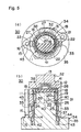
- FIG. 2(a) is a schematic plan view showing the step of assembling the magnets and the magnet cover.
- FIG. 2 (b) is a schematic sectional front view corresponding to FIG. 2(a).
- FIG. 3(a) is a schematic plan view showing the step of assembling the yoke.
- FIG. 3 (b) is a schematic sectional front view corresponding to FIG. 3 (a).
- FIG. 4(a) is a partly sectioned schematic plan view showing an initial stage of the press-fitting operation.
- FIG. 4(b) is a schematic sectional front view corresponding to FIG. 4(a).
- FIG. 5 (a) is a partly sectioned schematic plan view showing a final stage of the press-fitting cperation.
- FIG. 5(b) is a schematic sectional front view corresponding to FIG. 5(a).
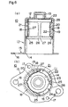
- FIG. 6 (a) is a sectional front view showing the rigidly secured yoke.
- FIG. 6(b) is a partly sectioned bottom view corresponding to FIG. 6 (a) .
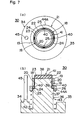
- FIG. 7(a) is a schematic plan view showing the step of assembling the magnets and the magnet cover of a second embodiment of the invention.
- FIG. 7(b) is a schematic sectional front view corresponding to FIG. 7(a).
- FIG. 8(a) is a partly sectioned schematic plan view showing the step of assembling the yoke.
- FIG. 8 (b) is a schematic sectional front view corresponding to FIG. 8(a).
- FIG. 9(a) is a partly sectioned schematic plan view showing an final stage of the press-fitting operation.
- FIG. 9(b) is a schematic sectional front view corresponding to FIG. 9(a).
- FIG. 1 is an exploded partly cut away perspective view showing a first embodiment of a method of securing magnets of a motor in position according to the present invention.
- FIGS. 2(a) through 5 (b) shows each step of securing the magnets of the motor.
- FIGS. 6(a) and 6(b) show a stator to which the magnets are rigidly secured.
- a method of securing magnets of a revolving electric machine of the invention is shown as a method of securing magnets of a motor using a hollow cylindrical yoke that is closed at an end.
- the stator 10 of the motor is formed integrally with a hollow cylindrical yoke 11 having a closed end by means of deep draw plastic working.
- the closure wall 12 of the yoke 11 has a bearing containing section 13 projecting therefrom as integral part thereof and formed integrally also by deep draw plastic working.
- the yoke 11 is provided at the outer periphery of the open end 14 thereof integrally with a radially and outwardly extending flange 15 that is substantially lozenge-shaped.
- the flange 15 has a plurality of through holes 16 for receiving screws for rigidly securing an end bracket in position.
- the flange 15 additionally has a plurality of aligning holes 17 arranged at predetermined positions.
- a total of four magnets 18 are arranged peripherally at regular intervals on the inner peripheral surface of the yoke 11 to form field poles of the motor.
- Each of the magnets is hexahedral of shape and has an arcuate cross section.
- the outer peripheral surfaces of the magnets 18 define an outer diameter D 19 substantially equal to the inner diameter of the yoke 11.
- the outer diameter D19 is slightly greater than the inner diameter of the yoke 11 before the magnets 18 are press-fitted into the yoke 11.
- the inner diameter D 20 defined by the inner peripheral surfaces 20 of the magnets 18 is slightly smaller than the outer diameter of the main body of a magnet cover before assembling, which will be described hereinafter.
- the magnet cover 21 is made of a very thin plate typically of stainless steel and has a hollow cylindrical profile. It is provided at the opposite ends thereof integrally with respective collars 23, 24 by plastic working. More specifically, the hollow cylindrical main body 22 of the magnet cover 21 has at an end thereof a coaxial circular inside collar 23 perpendicularly projecting radially and inwardly from the main body 22. And the main body 22 has at the other end thereof a coaxial circular outside collar 24 perpendicularly extending radially and outwardly from the main body 22.
- the outward collar 24 shows a width slightly smaller than the thickness of the magnets 18 before assembling.
- the outward collar 24 is provided peripherally and annularly with small holes 25 arranged at regular intervals, the number of which is equal to that of the magnets 18.
- the small holes 25 have a width in peripheral terms slightly greater than the gap separating any adjacently located two magnets 18, 18.
- a shallow cylindrical rigidity-providing section 26 is formed along an edge of the outer periphery of the outside collar 24 and extending axially outwardly from and coaxially with the outside collar 24.
- a method of rigidly securing magnets according to the invention is carried out by a magnet-securing device having a configuration as described below.
- the magnet securing device 30 has a press frame comprising an upper die and a lower die that are closed relative to each other by means of a press unit (not shown) .
- the upper die 31 is formed like a hanging bell shape and has an inner diameter slightly greater than the outer diameter of the yoke 11. It is adapted to abut the closure wall 12 of the yoke 11 and push down the latter from above.
- the upper die 31 is provided at the top thereof with a link section 32, by means of which the upper die 31 is linked to the ram of the press unit.
- the upper die 31 is further provided on the barrel thereof with a pair of yoke holders 33, which may be cylindrical holders or electromagnetic plungers.
- the yoke holders 33 are arranged oppositely relative to each other at positions where they do not interfere with the link sections 32.
- the yoke holders 33, 33 pinch the barrel of the yoke 11 from the opposite sides.
- the lower die 34 has a disc-shaped base 35 secured on the ground.
- a cylindrical column 36 is standing vertically and coaxially from the upper surface of the base 35 and has a large diameter section 37 and a small diameter section 38 separated by a step that provides a horizontal and annular receiving section 39 for receiving the outer collar 24 of the magnet cover 21.
- a total of four aligning projections 40 are standing axially from the upper surface of the receiving section 39 and arranged peripherally at regular intervals. The aligning projections 40 are received respectively by the four small holes 25 of the outer collar 24 of the magnet cover 21.
- a disc-shaped resilient body 41 of rubber or resin is bonded to the top of the column 36 by baking.
- the outer diameter of the small diameter section 38 is slightly smaller than that of inner diameter of the main body 22 of the magnet cover 21.
- the outer diameter of the large diameter section 37 is slightly smaller than the inner diameter of the section 26 of the magnet cover 21.
- a spring seat 42 is formed in an annular groove shape and it is arranged coaxially on the base 35 and around the outer periphery of the column 36.
- a compression coil spring (hereinafter simply referred to as spring) 43 is carried by the spring seat 42.
- An annular keep ring (magnet cover holding member) 44 is horizontally arranged at the top of the spring 43.
- the ring 44 partly covers both the section 37 and the section 38 of the column 36 by its inner peripheral surface and its top surface is located vis-à-vis with the lower surface of the flange 15 of the yoke 11.
- a guide pole 45 is vertically standing outside the spring seat 42 from the upper surface of the base 35 at a predetermined position relative to the projections 40. The guide pole 45 is adapted to pass through one of the through holes 16 of the yoke 11.
- a pair of substantially semi-circular magnet keep members (anti-fall jigs for the magnets) 46 are radially movably arranged outside the column 36.
- the members 46 are symmetrically arranged and extend upward from a position facing the receiving section 39.
- the two magnet keep members 46 are driven to move by means of cylindrical holders or electromagnetic plungers (not shown).
- the magnets of the motor are secured in position in a manner as described below by means of the above described magnet-securing device.
- the magnet cover 21 is made to cover the section 38 of the column 36 of the die 34 with the collar 24 facing downward in such a way that the section 26 of the magnet cover 21 becomes engaged with the large diameter section 37 of the column 36 and the projections 40 standing from the section 39 are received by the four respective small holes 25 of the collar 24.
- the collar 24 is stably received by the section 39.
- the collar 23 of the magnet cover 21 abuts the resilient body 41 on the top of the column 36 under this condition.
- each of the four magnets 18 is arranged between two adjacently located projections 40, 40 standing up from the collar 24 of the magnet cover 21 to substantially produce a ring of magnets.
- each of the magnets 18 is made to abut the inner peripheral surface of the ring 44 at the lower peripheral edge thereof so that it is temporarily secured there.
- the magnets 18 are peripherally aligned with the die 34 by means of the projections 40.
- the arranged four magnets 18 are pushed radially from outside by the pair of magnet keep members 46, 46 so that the magnets 18 would not fall radially outwardly.
- the yoke 11 that is held to the die 31 by means of the pair of yoke holders 33, 33 is arranged coaxially directly above the column 36 of the die 34. Then, the guide pole 45 of the die 34 is received by the corresponding through hole 16 of the yoke 11 to accurately align the magnets 18 and the yoke 11.
- the magnets 18 are placed coaxial with the yoke 11 and start to become press-fit into the yoke 11, pushing the magnet cover 21 radially inwardly.
- the pair of magnet keep members 46, 46 holding the magnets 18 can obstruct the downward movement of the yoke 11 relative to the magnets 18 and the magnet cover 21. Therefore, the members 46, 46 are made to move radially outwardly by means of the cylindrical holder as the die 31 is lowered so that they may not provide any obstacle to the lowering movement of the yoke 11.
- the outer diameter D 19 defined by the surfaces 19 of the magnets 18 before press-fitting operation is slightly greater than the inner diameter of the yoke 11.
- the inner diameter D 20 defined by the surfaces 20 of the magnets 18 after the press-fitting is slightly smaller than the outer diameter of the main body 22 of the magnet cover 21 before the press-fitting.
- the main body 22 of the magnet cover 21 is forced to outwardly bulge by the magnets 18 to produce bulged sections 27 to be used for peripheral alignment between any two adjacently located magnets 18, 18.
- the magnets 18 are prevented from moving peripherally by the bulged sections 27.
- the magnets 18 are pressed against the inner peripheral surface of the yoke 11 by the resilient force of the main body 22 of the magnet cover 21. Accordingly, the yoke 11, the magnets 18 and the magnet cover 21 are tightly and integrally held to each other. Still additionally, since the small diameter section 38 of the column 36 has an outer diameter slightly smaller than the inner diameter of the main body 22 of the magnet cover 21, the magnets 18 will be prevented from pressing against the section 38 and from cracking thereby.
- the resilient body 41 is compressed and forced to bulge radially outwardly by the closure wall 12 of the yoke 11 by way of the collar 23 of the magnet cover 21. Then, as the resilient body 41 bulges, the link section of the main body 22 connected to the collar 23 is also deformed to become bulged to produce an annular bulged section 28 for axial alignment. The bulged section 28 of the magnet cover 21 then engages the magnets 18 at the inner shoulder sections located close to the bottom wall of the yoke 11. Consequently, the magnets 18 are rigidly restricted for any axial movement between the bulged section 28 and the collar 24.
- the section 26 has an outer diameter slightly greater than the inner diameter of the yoke 11 before it is press-fitted into the yoke 11. Therefore, as the section 26 is press-fitted into the yoke 11, the magnet cover 21 is rigidly held to the inner periphery of the yoke 11 so that consequently the magnets 18 that are aligned by the magnet cover 21 are rigidly secured to the yoke 11.
- the die 31 is raised by the press unit, while the yoke 11 is pinched by the pair of yoke holders 33, 33 at the barrel thereof. Then, the yoke 11 rigidly holding the magnets 18 with the magnet cover 21 is released from the die 34 to produce a stator 10 having a configuration as shown in FIG. 6.
- the magnets 18 and the magnet cover 21 are positioned in the yoke 11 and the die 34, receiving the reaction force of the yoke 11, is introduced into the yoke 11 through the opening thereof, while the yoke 11 is pressed by the upper die 31.
- the yoke 11 does not have to be provided with through holes bored through the closure wall 12 thereof. Therefore, the motor is free from the operation of closing the through holes of the yoke 11 to secure hermetically sealing of the stator 10 after assembling the motor so that the overall manufacturing cost of the motor can be reduced.
- FIGS. 7(a) through 9(b) schematically illustrate a second embodiment of the method according to the present invention.
- the second embodiment differs from the above described first embodiment in that the keep ring 44A operates also as a magnet keep member, or an anti-side fall device, for the magnets 18. Note that the ring 44A extends above the receiving section 39 and further close to the die 31 than its counterpart of the first embodiment in order to push the magnets 18 from the side of the die 34.
- the magnet keep member 46 and the drive unit for driving the member can be omitted to further simplify the magnet securing device.
- the lower die may alternatively be made movable.
- a recess may be formed on the outer periphery of the yoke so that the yoke may be aligned with the upper die by means of the recess to omit the guide pole.
- the same press frame may be used for rigidly securing the magnets to a yoke having a differently profiled flange to improve the productivity of assembling stators.
- the present invention is not limited thereto and the present invention is also applicable to the process of rigidly securing magnets to the yoke of the rotor of the whole revolving electric machine such as a magnet generator.
Landscapes
- Engineering & Computer Science (AREA)
- Manufacturing & Machinery (AREA)
- Power Engineering (AREA)
- Permanent Field Magnets Of Synchronous Machinery (AREA)
- Permanent Magnet Type Synchronous Machine (AREA)
Description
- This invention relates to a method of securing the magnets of a rotating electric machine in position. More particularly, this invention relates to a method of rigidly securing magnets to the yoke of the stator of an electric motor (hereinafter referred to as motor) or that of the rotor of a magnet generator (fly-wheel magnet generator), which method may find a wide variety of applications in the field of manufacturing motors to be used for the electric equipment of automobiles.
- Electric motors comprising a plurality of magnets arranged annularly and peripherally at regular intervals along the inner peripheral surface of a hollow cylindrical yoke and rigidly secured in position by means of a hollow cylindrical magnet cover press-fitted to the inner peripheral surfaces of the magnets are widely used as the electric equipment of automobiles.
- As a conventional magnet securing method such as the above kind, there is a magnet cover built-in method for a permanent magnet motor shown in Japanese Patent Publication No. 5-59661. With the disclosed method of arranging a built-in type magnet cover, a hollow cylindrical yoke having openings at the opposite ends is used in an ingenious manner. More specifically, magnets are arranged annularly and peripherally at regular intervals along the inner peripheral surface of the yoke and supported by a magnets-aligning jig introduced from one of the openings of the yoke, and a magnet cover is introduced from the other opening of the yoke and press-fitted to the inner peripheral surfaces of the group of magnets.
- However, with the above described method, if a yoke with a closure wall end is used, the jig or the magnet cover cannot be introduced from the side of the closure wall of the yoke and it is impossible to arrange the magnet cover within the yoke.
- This problem may be bypassed by providing the closure wall of the yoke with an opening, through which the jig can be introduced to align and support the magnets. Then, however, the stator of the motor has to be provided with a sealing means for hermetically sealing the opening that is used to introduce the jig in order to align the magnets. Otherwise, the motor will be devoid of water-resistance.
- Document FR 2 707 813 A discloses a method of assembling an outer rotor, in which arcuate permanent magnets are arranged around the inner periphery of a cup-shaped housing and are held in place by a hollow cylindrical magnet cover. To assemble the rotor the magnets are arranged in position inside the cup-shaped housing, which is placed on the lower die of a press frame. The magnet cover is secured to an upper die of the press frame and is then forced down into the cylindrical space defined by the inner peripheries of the arcuate magnets.
- US 5 095 611 A discloses a method of assembling a stator comprising a pair of arcuate permanent magnets arranged around the inner periphery of a cup-shaped housing, in which the magnets are retained by axially extending spring clips inserted between them. In the assembly process the magnets and spring clips are arranged in their desired final relative positions on suitable positioning means on a lower die, and the cup-shaped housing is forced down over them.
- Therefore, the object of the present invention is to provide an alternative method of rigidly securing the magnets of a revolving electric machine in position, with which magnets can be rigidly secured to a hollow cylindrical yoke having an end closed without forming an opening through the closure wall of the yoke.
- According to the invention, the above object is achieved by providing a method of securing magnets of a rotating electric machine such that a plurality of magnets are annularly and peripherally arranged at regular intervals on the inner peripheral surface of a hollow cylindrical yoke having a closed end and rigidly secured by a hollow cylindrical magnet cover press-fitted to the inner peripheral surface of the magnets, characterized by comprising the steps of:
- temporarily holding the magnet cover by means of a lower die of a press frame having upper and lower dies to be closed relative to each other and arranging the plurality of magnets peripherally along the outer periphery of the magnet cover; and
- securing the yoke to the upper die, arranging the yoke coaxially relative to the magnet cover with the opening side of the yoke directed to the magnet cover, closing the upper die and the lower die relative to each other and then press-fitting the magnets and the magnet cover into the yoke, while pushing the outer peripheral surfaces of the magnets by means of the inner peripheral surface of the yoke.
-
- Further, the magnets arranged along the outer periphery of the magnet cover may be supported by a pair of anti-fall jigs for the magnets until the magnets are partly introduced into the yoke.
- Additionally, the anti-fall jigs maybe arranged radially movably relative to the upper and lower dies and the magnets arranged along the outer periphery of the magnet cover may be pushed radially from outside by the anti-fall jigs.
- Furthermore, the magnet cover may be held by a magnet cover holding member vertically movably fitted to the lower die.
- Additionally, the cover holding member may operate also as anti-fall jigs for holding the magnets and the magnets may be axially pushed from outside by the magnet cover holding member.
- For the purpose of the invention, the lower die may be provided with a resilient member adapted to abut the inside of the top of the magnet cover when the magnet cover is temporarily held by the lower die, the resilient member is compressed and radially and outwardly bulged by closing the upper and lower dies relative to each other, so that the magnet cover is deformed to become bulged to produce an annular bulged section for axial alignment.
- Further, a radially and outwardly projecting outside collar may be formed at an end of the magnet cover and provided with as many small holes as the magnets, the small holes being arranged at regular intervals corresponding to the intervals of the magnets; and
the lower die may be provided with aligning projections adapted to be received respectively by the small holes in order to peripherally align the magnets when the upper and lower dies are closed relative to each other. - With a method according to the invention, when the magnets are secured by the magnet cover, the magnets and the magnet cover are positioned in the yoke and the lower die, receiving the reaction force of the yoke, is introduced into the yoke through the opening thereof, while the yoke is pressed by the upper die. Thus, the yoke does not have to be provided with through holes bored through the closure wall thereof. Therefore, the motor is free from the operation of closing the through holes that will otherwise be necessary to hermetically seal the stator after assembling the motor so that the overall manufacturing cost of the motor can be reduced.
- The above described and other objects and novel features of the present invention will become apparent more fully from the following specification described in conjunction with the accompanying drawings.
- FIG. 1 is an exploded partly omitted perspective view showing a first embodiment of a method of securing magnets of a motor in position according to the present invention.
- FIG. 2(a) is a schematic plan view showing the step of assembling the magnets and the magnet cover.
- FIG. 2 (b) is a schematic sectional front view corresponding to FIG. 2(a).
- FIG. 3(a) is a schematic plan view showing the step of assembling the yoke.
- FIG. 3 (b) is a schematic sectional front view corresponding to FIG. 3 (a).
- FIG. 4(a) is a partly sectioned schematic plan view showing an initial stage of the press-fitting operation.
- FIG. 4(b) is a schematic sectional front view corresponding to FIG. 4(a).
- FIG. 5 (a) is a partly sectioned schematic plan view showing a final stage of the press-fitting cperation.
- FIG. 5(b) is a schematic sectional front view corresponding to FIG. 5(a).
- FIG. 6 (a) is a sectional front view showing the rigidly secured yoke.
- FIG. 6(b) is a partly sectioned bottom view corresponding to FIG. 6 (a) .
- FIG. 7(a) is a schematic plan view showing the step of assembling the magnets and the magnet cover of a second embodiment of the invention.
- FIG. 7(b) is a schematic sectional front view corresponding to FIG. 7(a).
- FIG. 8(a) is a partly sectioned schematic plan view showing the step of assembling the yoke.
- FIG. 8 (b) is a schematic sectional front view corresponding to FIG. 8(a).
- FIG. 9(a) is a partly sectioned schematic plan view showing an final stage of the press-fitting operation.
- FIG. 9(b) is a schematic sectional front view corresponding to FIG. 9(a).
- FIG. 1 is an exploded partly cut away perspective view showing a first embodiment of a method of securing magnets of a motor in position according to the present invention. FIGS. 2(a) through 5 (b) shows each step of securing the magnets of the motor. FIGS. 6(a) and 6(b) show a stator to which the magnets are rigidly secured.
- In this embodiment, a method of securing magnets of a revolving electric machine of the invention is shown as a method of securing magnets of a motor using a hollow cylindrical yoke that is closed at an end. The
stator 10 of the motor is formed integrally with a hollow cylindrical yoke 11 having a closed end by means of deep draw plastic working. Theclosure wall 12 of the yoke 11 has abearing containing section 13 projecting therefrom as integral part thereof and formed integrally also by deep draw plastic working. The yoke 11 is provided at the outer periphery of theopen end 14 thereof integrally with a radially and outwardly extendingflange 15 that is substantially lozenge-shaped. Theflange 15 has a plurality of throughholes 16 for receiving screws for rigidly securing an end bracket in position. Theflange 15 additionally has a plurality of aligningholes 17 arranged at predetermined positions. - A total of four
magnets 18 are arranged peripherally at regular intervals on the inner peripheral surface of the yoke 11 to form field poles of the motor. Each of the magnets is hexahedral of shape and has an arcuate cross section. When the fourmagnets 18 are press-fitted to the inner peripheral surface of the yoke 11, the outer peripheral surfaces of themagnets 18 define an outer diameter D 19 substantially equal to the inner diameter of the yoke 11. Note that the outer diameter D19 is slightly greater than the inner diameter of the yoke 11 before themagnets 18 are press-fitted into the yoke 11. Similarly, the inner diameter D 20 defined by the innerperipheral surfaces 20 of themagnets 18 is slightly smaller than the outer diameter of the main body of a magnet cover before assembling, which will be described hereinafter. - The
magnet cover 21 is made of a very thin plate typically of stainless steel and has a hollow cylindrical profile. It is provided at the opposite ends thereof integrally withrespective collars main body 22 of themagnet cover 21 has at an end thereof a coaxial circular insidecollar 23 perpendicularly projecting radially and inwardly from themain body 22. And themain body 22 has at the other end thereof a coaxial circularoutside collar 24 perpendicularly extending radially and outwardly from themain body 22. Theoutward collar 24 shows a width slightly smaller than the thickness of themagnets 18 before assembling. Theoutward collar 24 is provided peripherally and annularly withsmall holes 25 arranged at regular intervals, the number of which is equal to that of themagnets 18. Thesmall holes 25 have a width in peripheral terms slightly greater than the gap separating any adjacently located twomagnets section 26 is formed along an edge of the outer periphery of theoutside collar 24 and extending axially outwardly from and coaxially with theoutside collar 24. As a result, bulgedsections 27 for peripheral alignment and a bulgedsection 28 for axial alignment will be formed on themain body 22 of themagnet cover 21 by means of a method of rigidly securing magnets according to the invention in a manner as will be described hereinafter. - In this embodiment, a method of rigidly securing magnets according to the invention is carried out by a magnet-securing device having a configuration as described below. The
magnet securing device 30 has a press frame comprising an upper die and a lower die that are closed relative to each other by means of a press unit (not shown) . Theupper die 31 is formed like a hanging bell shape and has an inner diameter slightly greater than the outer diameter of the yoke 11. It is adapted to abut theclosure wall 12 of the yoke 11 and push down the latter from above. Theupper die 31 is provided at the top thereof with alink section 32, by means of which theupper die 31 is linked to the ram of the press unit. Theupper die 31 is further provided on the barrel thereof with a pair ofyoke holders 33, which may be cylindrical holders or electromagnetic plungers. Theyoke holders 33 are arranged oppositely relative to each other at positions where they do not interfere with thelink sections 32. Theyoke holders - The
lower die 34 has a disc-shapedbase 35 secured on the ground. Acylindrical column 36 is standing vertically and coaxially from the upper surface of thebase 35 and has alarge diameter section 37 and asmall diameter section 38 separated by a step that provides a horizontal andannular receiving section 39 for receiving theouter collar 24 of themagnet cover 21. A total of four aligningprojections 40 are standing axially from the upper surface of the receivingsection 39 and arranged peripherally at regular intervals. The aligningprojections 40 are received respectively by the foursmall holes 25 of theouter collar 24 of themagnet cover 21. A disc-shapedresilient body 41 of rubber or resin is bonded to the top of thecolumn 36 by baking. - The outer diameter of the
small diameter section 38 is slightly smaller than that of inner diameter of themain body 22 of themagnet cover 21. The outer diameter of thelarge diameter section 37 is slightly smaller than the inner diameter of thesection 26 of themagnet cover 21. - A
spring seat 42 is formed in an annular groove shape and it is arranged coaxially on thebase 35 and around the outer periphery of thecolumn 36. A compression coil spring (hereinafter simply referred to as spring) 43 is carried by thespring seat 42. An annular keep ring (magnet cover holding member) 44 is horizontally arranged at the top of thespring 43. Thering 44 partly covers both thesection 37 and thesection 38 of thecolumn 36 by its inner peripheral surface and its top surface is located vis-à-vis with the lower surface of theflange 15 of the yoke 11. Aguide pole 45 is vertically standing outside thespring seat 42 from the upper surface of the base 35 at a predetermined position relative to theprojections 40. Theguide pole 45 is adapted to pass through one of the throughholes 16 of the yoke 11. - A pair of substantially semi-circular magnet keep members (anti-fall jigs for the magnets) 46 are radially movably arranged outside the
column 36. Themembers 46 are symmetrically arranged and extend upward from a position facing the receivingsection 39. The two magnet keepmembers 46 are driven to move by means of cylindrical holders or electromagnetic plungers (not shown). - In this embodiment of carrying out the invention, the magnets of the motor are secured in position in a manner as described below by means of the above described magnet-securing device.
- Referring to FIG. 2, the
magnet cover 21 is made to cover thesection 38 of thecolumn 36 of the die 34 with thecollar 24 facing downward in such a way that thesection 26 of themagnet cover 21 becomes engaged with thelarge diameter section 37 of thecolumn 36 and theprojections 40 standing from thesection 39 are received by the four respectivesmall holes 25 of thecollar 24. Thus, thecollar 24 is stably received by thesection 39. Thecollar 23 of themagnet cover 21 abuts theresilient body 41 on the top of thecolumn 36 under this condition. - Subsequently, each of the four
magnets 18 is arranged between two adjacently locatedprojections collar 24 of themagnet cover 21 to substantially produce a ring of magnets. Note that each of themagnets 18 is made to abut the inner peripheral surface of thering 44 at the lower peripheral edge thereof so that it is temporarily secured there. Thus, themagnets 18 are peripherally aligned with the die 34 by means of theprojections 40. Then, the arranged fourmagnets 18 are pushed radially from outside by the pair of magnet keepmembers magnets 18 would not fall radially outwardly. - Referring to FIG. 3, the yoke 11 that is held to the die 31 by means of the pair of
yoke holders column 36 of thedie 34. Then, theguide pole 45 of the die 34 is received by the corresponding throughhole 16 of the yoke 11 to accurately align themagnets 18 and the yoke 11. - Then, referring to FIG. 4, as the
die 31 is gradually lowered by the press unit, the yoke 11 moves downward as it is guided by theguide pole 45 passing through the corresponding throughhole 16. Note that the top of the eachmagnets 18 is beveled along the outer peripheral edge thereof. The inner peripheral edge of theflange 15, that is, the boundary between theflange 15 and the cylindrical portion of the yoke 11 is rounded. Therefore, as the rounded inner peripheral edge of the yoke 11 or theflange 15 abuts the beveled outer peripheral edges of themagnets 18 and the yoke 11 is lowered further, themagnets 18 are placed coaxial with the yoke 11 and start to become press-fit into the yoke 11, pushing themagnet cover 21 radially inwardly. As the yoke 11 is lowered further, it slides on the outer peripheral surfaces of themagnets 18, pushing them radially inwardly by its inner peripheral surface because themagnets 18 and themagnet cover 21 are securely supported by thesection 39 of thedie 34. The pair of magnet keepmembers magnets 18 can obstruct the downward movement of the yoke 11 relative to themagnets 18 and themagnet cover 21. Therefore, themembers die 31 is lowered so that they may not provide any obstacle to the lowering movement of the yoke 11. - The outer diameter D 19 defined by the
surfaces 19 of themagnets 18 before press-fitting operation is slightly greater than the inner diameter of the yoke 11. Similarly, the inner diameter D 20 defined by thesurfaces 20 of themagnets 18 after the press-fitting is slightly smaller than the outer diameter of themain body 22 of themagnet cover 21 before the press-fitting. Thus, themagnets 18 and themagnet cover 21 are successfully press-fitted into the yoke 11 as a result of the relative movement of the yoke 11 and themagnets 18 and themagnet cover 21. As themagnets 18 are pushed radially inwardly by the yoke 11, themain body 22 of themagnet cover 21 is pushed radially inwardly by themagnets 18. - As a result, the
main body 22 of themagnet cover 21 is forced to outwardly bulge by themagnets 18 to produce bulgedsections 27 to be used for peripheral alignment between any two adjacently locatedmagnets magnets 18 are prevented from moving peripherally by the bulgedsections 27. Additionally, themagnets 18 are pressed against the inner peripheral surface of the yoke 11 by the resilient force of themain body 22 of themagnet cover 21. Accordingly, the yoke 11, themagnets 18 and themagnet cover 21 are tightly and integrally held to each other. Still additionally, since thesmall diameter section 38 of thecolumn 36 has an outer diameter slightly smaller than the inner diameter of themain body 22 of themagnet cover 21, themagnets 18 will be prevented from pressing against thesection 38 and from cracking thereby. - As the yoke 11 is pushed downward by the die 31 to complete its final stroke as shown in FIG. 5, the
resilient body 41 is compressed and forced to bulge radially outwardly by theclosure wall 12 of the yoke 11 by way of thecollar 23 of themagnet cover 21. Then, as theresilient body 41 bulges, the link section of themain body 22 connected to thecollar 23 is also deformed to become bulged to produce anannular bulged section 28 for axial alignment. The bulgedsection 28 of themagnet cover 21 then engages themagnets 18 at the inner shoulder sections located close to the bottom wall of the yoke 11. Consequently, themagnets 18 are rigidly restricted for any axial movement between the bulgedsection 28 and thecollar 24. - Note that the
section 26 has an outer diameter slightly greater than the inner diameter of the yoke 11 before it is press-fitted into the yoke 11. Therefore, as thesection 26 is press-fitted into the yoke 11, themagnet cover 21 is rigidly held to the inner periphery of the yoke 11 so that consequently themagnets 18 that are aligned by themagnet cover 21 are rigidly secured to the yoke 11. - Subsequently, the
die 31 is raised by the press unit, while the yoke 11 is pinched by the pair ofyoke holders magnets 18 with themagnet cover 21 is released from the die 34 to produce astator 10 having a configuration as shown in FIG. 6. - With the above described embodiment, when the
magnets 18 are secured by themagnet cover 21, themagnets 18 and themagnet cover 21 are positioned in the yoke 11 and thedie 34, receiving the reaction force of the yoke 11, is introduced into the yoke 11 through the opening thereof, while the yoke 11 is pressed by theupper die 31. Thus, the yoke 11 does not have to be provided with through holes bored through theclosure wall 12 thereof. Therefore, the motor is free from the operation of closing the through holes of the yoke 11 to secure hermetically sealing of thestator 10 after assembling the motor so that the overall manufacturing cost of the motor can be reduced. - FIGS. 7(a) through 9(b) schematically illustrate a second embodiment of the method according to the present invention.
- The second embodiment differs from the above described first embodiment in that the
keep ring 44A operates also as a magnet keep member, or an anti-side fall device, for themagnets 18. Note that thering 44A extends above the receivingsection 39 and further close to the die 31 than its counterpart of the first embodiment in order to push themagnets 18 from the side of thedie 34. - With the second embodiment, the magnet keep
member 46 and the drive unit for driving the member can be omitted to further simplify the magnet securing device. - Detailed description has hereinabove been give of the invention achieved by the present inventor with reference to the embodiments. However, the present invention should not be limited to the embodiments described above and may be variously modified within the scope defined by the appended claims.
- For example, while the upper die is movable in the above embodiments, the lower die may alternatively be made movable. Additionally, a recess may be formed on the outer periphery of the yoke so that the yoke may be aligned with the upper die by means of the recess to omit the guide pole. When the guide pole is omitted, the same press frame may be used for rigidly securing the magnets to a yoke having a differently profiled flange to improve the productivity of assembling stators.
- Additionally, while the magnets are rigidly secured to the yoke of the stator of a motor in the above embodiments, the present invention is not limited thereto and the present invention is also applicable to the process of rigidly securing magnets to the yoke of the rotor of the whole revolving electric machine such as a magnet generator.
Claims (7)
- A method of securing magnets of a rotating electric machine such that a plurality of magnets (18) are annularly and peripherally arranged at regular intervals on the inner peripheral surface of a hollow cylindrical yoke (11) having a closed end (12) and rigidly secured by a hollow cylindrical magnet cover (21) press-fitted to the inner peripheral surface (20) of the magnets, characterized by comprising the steps of:temporarily holding the magnet cover (21) by means of a lower die (34) of a press frame having upper (31) and lower (34) dies to be closed relative to each other and arranging said plurality of magnets (18) peripherally along the outer periphery of the magnet cover; andsecuring said yoke (11) to the upper die (31) of said press frame, arranging said yoke coaxially relative to said magnet cover (21) with the opening side (14) of said yoke directed to said magnet cover, closing said upper die (31) and said lower die (34) relative to each other and then press-fitting said magnets (18) and said magnet cover (21) into said yoke (11), while pushing the outer peripheral surfaces of said magnets by means of the inner peripheral surface of said yoke.
- A method of securing magnets of a rotating electric machine according to claim 1, characterized in that said magnets (18) arranged along the outer periphery of the magnet cover (21) are supported by a pair of anti-fall jigs (46) for the magnets until said magnets are partly introduced into the yoke.
- A method of securing magnets of a rotating electric machine according to claim 2, characterized in that said anti-fall jigs (46) are arranged radially movably relative to said upper and lower dies (31, 34) and said magnets (18) arranged along the outer periphery of said magnet cover are pushed radially from outside by said anti-fall jigs.
- A method of securing magnets of a rotating electric machine according to claim 1, characterized in that said magnet cover (21) is held by a magnet cover holding member (44, 44A) vertically movably fitted to said lower die (34).
- A method of securing magnets of a rotating electric machine according to claim 4, characterized in that said cover holding member (44A) operates also as anti-fall jigs for the magnets (18) for holding said magnets and said magnets are axially pushed from outside by said magnet cover holding member (44A).
- A method of securing magnets of a rotating electric machine according to claim 1, characterized in that said lower die (34) is provided with a resilient member (41) adapted to abut the inside of the top of said magnet cover (21) when said magnet cover is temporarily held by said lower die, said resilient member is compressed and radially and outwardly bulged by closing said upper and lower dies (31, 34) relative to each other, so that said magnet cover is deformed to become bulged to produce an annular bulged section (28) for axial alignment.
- A method of securing magnets of a rotating electric machine according to claim 1, characterized in that a radially and outwardly projecting outside collar (24) is formed at an end of said magnet cover (21) and provided with as many small holes (25) as said magnets (18), said small holes being arranged at regular intervals corresponding to the intervals of said magnets; and
said lower die (34) is provided with aligning projections (40) adapted to be received respectively by said small holes (25) in order to peripherally align said magnets (18) when said upper and lower dies are closed relative to each other.
Applications Claiming Priority (3)
| Application Number | Priority Date | Filing Date | Title |
|---|---|---|---|
| JP21138497A JP3809978B2 (en) | 1997-07-22 | 1997-07-22 | Magnet fixing method for rotating electric machine |
| JP211384/97 | 1997-07-22 | ||
| JP21138497 | 1997-07-22 |
Publications (2)
| Publication Number | Publication Date |
|---|---|
| EP0893873A1 EP0893873A1 (en) | 1999-01-27 |
| EP0893873B1 true EP0893873B1 (en) | 2003-03-26 |
Family
ID=16605074
Family Applications (1)
| Application Number | Title | Priority Date | Filing Date |
|---|---|---|---|
| EP98401643A Expired - Fee Related EP0893873B1 (en) | 1997-07-22 | 1998-07-01 | Method of securing magnets of a rotating electric machine |
Country Status (7)
| Country | Link |
|---|---|
| US (1) | US6199265B1 (en) |
| EP (1) | EP0893873B1 (en) |
| JP (1) | JP3809978B2 (en) |
| CN (1) | CN1201466C (en) |
| DE (1) | DE69812494T2 (en) |
| ID (1) | ID20614A (en) |
| TW (1) | TW370734B (en) |
Families Citing this family (14)
| Publication number | Priority date | Publication date | Assignee | Title |
|---|---|---|---|---|
| US8035273B2 (en) | 2005-12-08 | 2011-10-11 | A.O. Smith Corporation | Rotor assembly having two core portions each with a reduced back portion |
| US20070132335A1 (en) * | 2005-12-08 | 2007-06-14 | Ionel Dan M | Rotor assembly having a reduced back portion and a method of manufacturing same |
| WO2007123171A1 (en) * | 2006-04-19 | 2007-11-01 | Mitsuba Corporation | Rotor for magnet-type generator, magnet-type generator, method of producing rotor for magnet-type generator, and device for producing rotor for magnet-type generator |
| KR100722613B1 (en) * | 2006-04-20 | 2007-05-28 | 삼성전기주식회사 | Jig for assembling a rotor |
| KR101279774B1 (en) * | 2009-03-30 | 2013-07-04 | 주식회사 만도 | Torque Rotor and Manufacturing Method of The Same |
| KR101135333B1 (en) * | 2011-04-13 | 2012-04-17 | 뉴모텍(주) | Stator for motor and method for manufacturing the stator |
| CN102779613B (en) * | 2012-07-20 | 2013-11-27 | 杭州新世宝电动转向系统有限公司 | Gap eliminating type magnetizing clamp |
| CN103066765B (en) * | 2012-12-13 | 2015-10-28 | 浙江联宜电机股份有限公司 | Motor dress magnetic ring device |
| CN104384361B (en) * | 2014-10-31 | 2016-05-04 | 平高集团有限公司 | A kind of assembly tooling of electromagnetic lock yoke device |
| KR200481038Y1 (en) * | 2015-01-14 | 2016-08-04 | (주)성우 | Clamping jig for stator of the motor housing |
| CN107846119B (en) * | 2017-08-11 | 2019-07-09 | 马鞍山和腾汽车配件有限公司 | A kind of assembly method of expansion chuck starter stator assembly |
| CN107394973B (en) * | 2017-08-11 | 2023-12-01 | 濮阳市顺达油气工程技术有限公司 | Assembling device for starter stator assembly |
| CN108494191B (en) * | 2018-05-31 | 2023-10-13 | 浙江联宜电机有限公司 | Direct current motor magnetic shoe and spring clip mounting device |
| US20230361661A1 (en) * | 2020-09-30 | 2023-11-09 | Aichi Steel Corporation | Method for manufacturing field magnet |
Family Cites Families (11)
| Publication number | Priority date | Publication date | Assignee | Title |
|---|---|---|---|---|
| JPS61199448A (en) * | 1985-02-28 | 1986-09-03 | Fanuc Ltd | Permanent magnet field rotor assembly |
| US5319844A (en) * | 1985-12-23 | 1994-06-14 | Unique Mobility, Inc. | Method of making an electromagnetic transducer |
| US4829657A (en) * | 1987-02-27 | 1989-05-16 | Maxtor Corporation | In-spindle motor assembly for disk drive and method for fabricating the same |
| FR2632788B1 (en) | 1988-06-08 | 1995-07-13 | Gen Electric | PERMANENT MAGNET ROTORS, MANUFACTURING METHODS AND DEVICES |
| US5040286A (en) | 1988-06-08 | 1991-08-20 | General Electric Company | Method for making permanent magnet rotor |
| GB2227890B (en) * | 1988-12-02 | 1993-08-04 | Johnson Electric Ind Mfg | Axially securing an armature stack in an electric motor |
| US5005281A (en) * | 1990-08-20 | 1991-04-09 | Dynamics Systems International Inc. | Method of making rotor and stator pole assemblies by stamping magnetic plate |
| US5095611A (en) | 1991-03-05 | 1992-03-17 | Siemens Automotive Limited | Method of assembling an electric motor to eliminate a separate end play adjustment |
| IT1246925B (en) * | 1991-04-04 | 1994-11-29 | Ricerca Elettromeccanica Srl | METHOD FOR THE PRODUCTION OF PARTS OF ELECTRIC MOTORS AND MOTORS USING PARTS PRODUCED WITH THAT METHOD |
| JPH0559661A (en) | 1991-08-30 | 1993-03-09 | Meito Sci Kk | Cloth structure and method for detecting its stitch |
| ES2103645B1 (en) | 1993-07-16 | 1998-04-16 | Mitsuba Corp | MAGNETO ROTOR AND PROCEDURE FOR ITS MANUFACTURE. |
-
1997
- 1997-07-22 JP JP21138497A patent/JP3809978B2/en not_active Expired - Fee Related
-
1998
- 1998-06-30 US US09/107,727 patent/US6199265B1/en not_active Expired - Lifetime
- 1998-07-01 EP EP98401643A patent/EP0893873B1/en not_active Expired - Fee Related
- 1998-07-01 DE DE69812494T patent/DE69812494T2/en not_active Expired - Fee Related
- 1998-07-13 TW TW087111311A patent/TW370734B/en active
- 1998-07-21 CN CN98116133.2A patent/CN1201466C/en not_active Expired - Fee Related
- 1998-07-22 ID IDP981035A patent/ID20614A/en unknown
Also Published As
| Publication number | Publication date |
|---|---|
| CN1201466C (en) | 2005-05-11 |
| JPH1141842A (en) | 1999-02-12 |
| CN1206236A (en) | 1999-01-27 |
| DE69812494T2 (en) | 2003-09-11 |
| US6199265B1 (en) | 2001-03-13 |
| TW370734B (en) | 1999-09-21 |
| EP0893873A1 (en) | 1999-01-27 |
| DE69812494D1 (en) | 2003-04-30 |
| JP3809978B2 (en) | 2006-08-16 |
| ID20614A (en) | 1999-01-28 |
Similar Documents
| Publication | Publication Date | Title |
|---|---|---|
| EP0893873B1 (en) | Method of securing magnets of a rotating electric machine | |
| US7230357B2 (en) | External rotor motor and method for assembling such a motor | |
| CN108616175B (en) | Brush permanent magnet micromotor and assembling method thereof | |
| KR102223977B1 (en) | Electric machine for motor-adjusting movable parts in motor vehicle, and method for manufacturing the electric machine | |
| KR20040094336A (en) | Stepping motor and method of manufacturing stepping motor | |
| KR890009047A (en) | Hermetic Step Motor | |
| EP1330014B1 (en) | Electric motor | |
| JPH1118353A (en) | Small-sized motor | |
| US20070040456A1 (en) | Linear compressor, particularly refrigerant compressor | |
| CN212412923U (en) | Motor | |
| CN106533092B (en) | Stator casing punching tool | |
| JPH07118873B2 (en) | Magnet generator rotor | |
| KR100273431B1 (en) | Motor Core Fixed Structure of Linear Compressor | |
| KR102634721B1 (en) | Hollow Shaft Motor | |
| CN212063658U (en) | Rotor and motor | |
| JP6247655B2 (en) | Manufacturing method of outer rotor type motor | |
| CN108900051B (en) | Assembling method of permanent magnet servo motor | |
| CN218335704U (en) | Small-sized linear motor with complete machine vibration | |
| KR20080035526A (en) | Bearing device, method for fixing a bearing device and electric machine provided therewith | |
| KR102351783B1 (en) | Hollow Shaft Motor | |
| US20220329119A1 (en) | Rotor Device and Stator Device for a Flat Brushless Electric Motor and Flat, Brushless Electric Motor for Roof System of an Automobile | |
| CN209913592U (en) | Rotor unit for an electric motor and electric motor | |
| WO2007123171A1 (en) | Rotor for magnet-type generator, magnet-type generator, method of producing rotor for magnet-type generator, and device for producing rotor for magnet-type generator | |
| WO1998058520A1 (en) | Loudspeakers | |
| KR100446967B1 (en) | Apparatus for vibrator in linear motor |
Legal Events
| Date | Code | Title | Description |
|---|---|---|---|
| PUAI | Public reference made under article 153(3) epc to a published international application that has entered the european phase |
Free format text: ORIGINAL CODE: 0009012 |
|
| AK | Designated contracting states |
Kind code of ref document: A1 Designated state(s): DE FR IT |
|
| AX | Request for extension of the european patent |
Free format text: AL;LT;LV;MK;RO;SI |
|
| 17P | Request for examination filed |
Effective date: 19990127 |
|
| AKX | Designation fees paid |
Free format text: DE FR IT |
|
| RTI1 | Title (correction) |
Free format text: METHOD OF SECURING MAGNETS OF A ROTATING ELECTRIC MACHINE |
|
| GRAH | Despatch of communication of intention to grant a patent |
Free format text: ORIGINAL CODE: EPIDOS IGRA |
|
| GRAH | Despatch of communication of intention to grant a patent |
Free format text: ORIGINAL CODE: EPIDOS IGRA |
|
| GRAA | (expected) grant |
Free format text: ORIGINAL CODE: 0009210 |
|
| AK | Designated contracting states |
Designated state(s): DE FR IT |
|
| REF | Corresponds to: |
Ref document number: 69812494 Country of ref document: DE Date of ref document: 20030430 Kind code of ref document: P |
|
| ET | Fr: translation filed | ||
| PLBE | No opposition filed within time limit |
Free format text: ORIGINAL CODE: 0009261 |
|
| STAA | Information on the status of an ep patent application or granted ep patent |
Free format text: STATUS: NO OPPOSITION FILED WITHIN TIME LIMIT |
|
| 26N | No opposition filed |
Effective date: 20031230 |
|
| PGFP | Annual fee paid to national office [announced via postgrant information from national office to epo] |
Ref country code: FR Payment date: 20040708 Year of fee payment: 7 Ref country code: DE Payment date: 20040708 Year of fee payment: 7 |
|
| PG25 | Lapsed in a contracting state [announced via postgrant information from national office to epo] |
Ref country code: IT Free format text: LAPSE BECAUSE OF NON-PAYMENT OF DUE FEES;WARNING: LAPSES OF ITALIAN PATENTS WITH EFFECTIVE DATE BEFORE 2007 MAY HAVE OCCURRED AT ANY TIME BEFORE 2007. THE CORRECT EFFECTIVE DATE MAY BE DIFFERENT FROM THE ONE RECORDED. Effective date: 20050701 |
|
| PG25 | Lapsed in a contracting state [announced via postgrant information from national office to epo] |
Ref country code: DE Free format text: LAPSE BECAUSE OF NON-PAYMENT OF DUE FEES Effective date: 20060201 |
|
| PG25 | Lapsed in a contracting state [announced via postgrant information from national office to epo] |
Ref country code: FR Free format text: LAPSE BECAUSE OF NON-PAYMENT OF DUE FEES Effective date: 20060331 |
|
| REG | Reference to a national code |
Ref country code: FR Ref legal event code: ST Effective date: 20060331 |