EP0893665B1 - Method and apparatus for regulatory control of production and temperature in a mixed refrigerant liquefied natural gas facility - Google Patents
Method and apparatus for regulatory control of production and temperature in a mixed refrigerant liquefied natural gas facility Download PDFInfo
- Publication number
- EP0893665B1 EP0893665B1 EP98113583A EP98113583A EP0893665B1 EP 0893665 B1 EP0893665 B1 EP 0893665B1 EP 98113583 A EP98113583 A EP 98113583A EP 98113583 A EP98113583 A EP 98113583A EP 0893665 B1 EP0893665 B1 EP 0893665B1
- Authority
- EP
- European Patent Office
- Prior art keywords
- refrigerant
- compressor
- flow rate
- temperature
- lng
- Prior art date
- Legal status (The legal status is an assumption and is not a legal conclusion. Google has not performed a legal analysis and makes no representation as to the accuracy of the status listed.)
- Expired - Lifetime
Links
- 239000003949 liquefied natural gas Substances 0.000 title claims description 330
- 239000003507 refrigerant Substances 0.000 title claims description 188
- 238000000034 method Methods 0.000 title claims description 126
- 238000004519 manufacturing process Methods 0.000 title claims description 48
- 230000001105 regulatory effect Effects 0.000 title description 5
- VNWKTOKETHGBQD-UHFFFAOYSA-N methane Chemical compound C VNWKTOKETHGBQD-UHFFFAOYSA-N 0.000 claims description 108
- 238000005057 refrigeration Methods 0.000 claims description 68
- 230000008569 process Effects 0.000 claims description 61
- 230000006870 function Effects 0.000 claims description 58
- 239000003345 natural gas Substances 0.000 claims description 53
- 239000007788 liquid Substances 0.000 claims description 39
- 230000008859 change Effects 0.000 claims description 16
- 239000000203 mixture Substances 0.000 claims description 14
- 238000013461 design Methods 0.000 claims description 11
- 238000004364 calculation method Methods 0.000 claims description 9
- 238000001816 cooling Methods 0.000 claims description 9
- 238000005457 optimization Methods 0.000 claims description 8
- 230000003247 decreasing effect Effects 0.000 claims description 5
- 238000001704 evaporation Methods 0.000 claims 2
- 230000008020 evaporation Effects 0.000 claims 2
- 230000005540 biological transmission Effects 0.000 claims 1
- 238000012546 transfer Methods 0.000 description 27
- 230000009467 reduction Effects 0.000 description 23
- 238000013404 process transfer Methods 0.000 description 17
- 230000004044 response Effects 0.000 description 13
- 238000010586 diagram Methods 0.000 description 11
- 238000004088 simulation Methods 0.000 description 8
- 238000007906 compression Methods 0.000 description 7
- 230000006835 compression Effects 0.000 description 7
- ATUOYWHBWRKTHZ-UHFFFAOYSA-N Propane Chemical compound CCC ATUOYWHBWRKTHZ-UHFFFAOYSA-N 0.000 description 6
- 230000000694 effects Effects 0.000 description 6
- 239000007921 spray Substances 0.000 description 6
- 230000009471 action Effects 0.000 description 5
- 230000001419 dependent effect Effects 0.000 description 5
- 230000002829 reductive effect Effects 0.000 description 5
- XLYOFNOQVPJJNP-UHFFFAOYSA-N water Substances O XLYOFNOQVPJJNP-UHFFFAOYSA-N 0.000 description 5
- 238000004590 computer program Methods 0.000 description 4
- 238000005094 computer simulation Methods 0.000 description 4
- 238000011217 control strategy Methods 0.000 description 4
- 230000001276 controlling effect Effects 0.000 description 4
- 229930195733 hydrocarbon Natural products 0.000 description 4
- 150000002430 hydrocarbons Chemical class 0.000 description 4
- 238000000926 separation method Methods 0.000 description 4
- UHOVQNZJYSORNB-UHFFFAOYSA-N Benzene Chemical compound C1=CC=CC=C1 UHOVQNZJYSORNB-UHFFFAOYSA-N 0.000 description 3
- 101100333868 Homo sapiens EVA1A gene Proteins 0.000 description 3
- 102100031798 Protein eva-1 homolog A Human genes 0.000 description 3
- 101100310674 Tenebrio molitor SP23 gene Proteins 0.000 description 3
- 230000007423 decrease Effects 0.000 description 3
- 238000005259 measurement Methods 0.000 description 3
- 239000001294 propane Substances 0.000 description 3
- 230000003134 recirculating effect Effects 0.000 description 3
- 239000012808 vapor phase Substances 0.000 description 3
- 101100365087 Arabidopsis thaliana SCRA gene Proteins 0.000 description 2
- IJGRMHOSHXDMSA-UHFFFAOYSA-N Atomic nitrogen Chemical compound N#N IJGRMHOSHXDMSA-UHFFFAOYSA-N 0.000 description 2
- 230000008901 benefit Effects 0.000 description 2
- 230000033228 biological regulation Effects 0.000 description 2
- 238000011143 downstream manufacturing Methods 0.000 description 2
- 239000012530 fluid Substances 0.000 description 2
- 239000007791 liquid phase Substances 0.000 description 2
- 239000000463 material Substances 0.000 description 2
- 238000003860 storage Methods 0.000 description 2
- 238000012360 testing method Methods 0.000 description 2
- 230000001052 transient effect Effects 0.000 description 2
- 230000008016 vaporization Effects 0.000 description 2
- 238000009834 vaporization Methods 0.000 description 2
- OTMSDBZUPAUEDD-UHFFFAOYSA-N Ethane Chemical compound CC OTMSDBZUPAUEDD-UHFFFAOYSA-N 0.000 description 1
- 230000002411 adverse Effects 0.000 description 1
- 239000012080 ambient air Substances 0.000 description 1
- 238000004458 analytical method Methods 0.000 description 1
- 238000013459 approach Methods 0.000 description 1
- 230000009286 beneficial effect Effects 0.000 description 1
- 238000004422 calculation algorithm Methods 0.000 description 1
- 230000002301 combined effect Effects 0.000 description 1
- 150000001875 compounds Chemical class 0.000 description 1
- 238000009833 condensation Methods 0.000 description 1
- 230000005494 condensation Effects 0.000 description 1
- -1 for example Chemical class 0.000 description 1
- 238000007710 freezing Methods 0.000 description 1
- 230000008014 freezing Effects 0.000 description 1
- 239000000446 fuel Substances 0.000 description 1
- 239000007789 gas Substances 0.000 description 1
- 230000008571 general function Effects 0.000 description 1
- 239000012535 impurity Substances 0.000 description 1
- 238000012544 monitoring process Methods 0.000 description 1
- 229910052757 nitrogen Inorganic materials 0.000 description 1
- 238000005312 nonlinear dynamic Methods 0.000 description 1
- 230000036961 partial effect Effects 0.000 description 1
- 239000012071 phase Substances 0.000 description 1
- 230000002265 prevention Effects 0.000 description 1
- 238000012545 processing Methods 0.000 description 1
- 230000002441 reversible effect Effects 0.000 description 1
- 238000012776 robust process Methods 0.000 description 1
- 230000026676 system process Effects 0.000 description 1
Images


Classifications
-
- G—PHYSICS
- G05—CONTROLLING; REGULATING
- G05B—CONTROL OR REGULATING SYSTEMS IN GENERAL; FUNCTIONAL ELEMENTS OF SUCH SYSTEMS; MONITORING OR TESTING ARRANGEMENTS FOR SUCH SYSTEMS OR ELEMENTS
- G05B19/00—Programme-control systems
- G05B19/02—Programme-control systems electric
- G05B19/418—Total factory control, i.e. centrally controlling a plurality of machines, e.g. direct or distributed numerical control [DNC], flexible manufacturing systems [FMS], integrated manufacturing systems [IMS], computer integrated manufacturing [CIM]
-
- F—MECHANICAL ENGINEERING; LIGHTING; HEATING; WEAPONS; BLASTING
- F25—REFRIGERATION OR COOLING; COMBINED HEATING AND REFRIGERATION SYSTEMS; HEAT PUMP SYSTEMS; MANUFACTURE OR STORAGE OF ICE; LIQUEFACTION SOLIDIFICATION OF GASES
- F25J—LIQUEFACTION, SOLIDIFICATION OR SEPARATION OF GASES OR GASEOUS OR LIQUEFIED GASEOUS MIXTURES BY PRESSURE AND COLD TREATMENT OR BY BRINGING THEM INTO THE SUPERCRITICAL STATE
- F25J1/00—Processes or apparatus for liquefying or solidifying gases or gaseous mixtures
- F25J1/0002—Processes or apparatus for liquefying or solidifying gases or gaseous mixtures characterised by the fluid to be liquefied
- F25J1/0022—Hydrocarbons, e.g. natural gas
-
- F—MECHANICAL ENGINEERING; LIGHTING; HEATING; WEAPONS; BLASTING
- F25—REFRIGERATION OR COOLING; COMBINED HEATING AND REFRIGERATION SYSTEMS; HEAT PUMP SYSTEMS; MANUFACTURE OR STORAGE OF ICE; LIQUEFACTION SOLIDIFICATION OF GASES
- F25J—LIQUEFACTION, SOLIDIFICATION OR SEPARATION OF GASES OR GASEOUS OR LIQUEFIED GASEOUS MIXTURES BY PRESSURE AND COLD TREATMENT OR BY BRINGING THEM INTO THE SUPERCRITICAL STATE
- F25J1/00—Processes or apparatus for liquefying or solidifying gases or gaseous mixtures
- F25J1/003—Processes or apparatus for liquefying or solidifying gases or gaseous mixtures characterised by the kind of cold generation within the liquefaction unit for compensating heat leaks and liquid production
- F25J1/0047—Processes or apparatus for liquefying or solidifying gases or gaseous mixtures characterised by the kind of cold generation within the liquefaction unit for compensating heat leaks and liquid production using an "external" refrigerant stream in a closed vapor compression cycle
- F25J1/0052—Processes or apparatus for liquefying or solidifying gases or gaseous mixtures characterised by the kind of cold generation within the liquefaction unit for compensating heat leaks and liquid production using an "external" refrigerant stream in a closed vapor compression cycle by vaporising a liquid refrigerant stream
- F25J1/0055—Processes or apparatus for liquefying or solidifying gases or gaseous mixtures characterised by the kind of cold generation within the liquefaction unit for compensating heat leaks and liquid production using an "external" refrigerant stream in a closed vapor compression cycle by vaporising a liquid refrigerant stream originating from an incorporated cascade
-
- F—MECHANICAL ENGINEERING; LIGHTING; HEATING; WEAPONS; BLASTING
- F25—REFRIGERATION OR COOLING; COMBINED HEATING AND REFRIGERATION SYSTEMS; HEAT PUMP SYSTEMS; MANUFACTURE OR STORAGE OF ICE; LIQUEFACTION SOLIDIFICATION OF GASES
- F25J—LIQUEFACTION, SOLIDIFICATION OR SEPARATION OF GASES OR GASEOUS OR LIQUEFIED GASEOUS MIXTURES BY PRESSURE AND COLD TREATMENT OR BY BRINGING THEM INTO THE SUPERCRITICAL STATE
- F25J1/00—Processes or apparatus for liquefying or solidifying gases or gaseous mixtures
- F25J1/003—Processes or apparatus for liquefying or solidifying gases or gaseous mixtures characterised by the kind of cold generation within the liquefaction unit for compensating heat leaks and liquid production
- F25J1/0047—Processes or apparatus for liquefying or solidifying gases or gaseous mixtures characterised by the kind of cold generation within the liquefaction unit for compensating heat leaks and liquid production using an "external" refrigerant stream in a closed vapor compression cycle
- F25J1/0052—Processes or apparatus for liquefying or solidifying gases or gaseous mixtures characterised by the kind of cold generation within the liquefaction unit for compensating heat leaks and liquid production using an "external" refrigerant stream in a closed vapor compression cycle by vaporising a liquid refrigerant stream
- F25J1/0057—Processes or apparatus for liquefying or solidifying gases or gaseous mixtures characterised by the kind of cold generation within the liquefaction unit for compensating heat leaks and liquid production using an "external" refrigerant stream in a closed vapor compression cycle by vaporising a liquid refrigerant stream after expansion of the liquid refrigerant stream with extraction of work
-
- F—MECHANICAL ENGINEERING; LIGHTING; HEATING; WEAPONS; BLASTING
- F25—REFRIGERATION OR COOLING; COMBINED HEATING AND REFRIGERATION SYSTEMS; HEAT PUMP SYSTEMS; MANUFACTURE OR STORAGE OF ICE; LIQUEFACTION SOLIDIFICATION OF GASES
- F25J—LIQUEFACTION, SOLIDIFICATION OR SEPARATION OF GASES OR GASEOUS OR LIQUEFIED GASEOUS MIXTURES BY PRESSURE AND COLD TREATMENT OR BY BRINGING THEM INTO THE SUPERCRITICAL STATE
- F25J1/00—Processes or apparatus for liquefying or solidifying gases or gaseous mixtures
- F25J1/02—Processes or apparatus for liquefying or solidifying gases or gaseous mixtures requiring the use of refrigeration, e.g. of helium or hydrogen ; Details and kind of the refrigeration system used; Integration with other units or processes; Controlling aspects of the process
- F25J1/0211—Processes or apparatus for liquefying or solidifying gases or gaseous mixtures requiring the use of refrigeration, e.g. of helium or hydrogen ; Details and kind of the refrigeration system used; Integration with other units or processes; Controlling aspects of the process using a multi-component refrigerant [MCR] fluid in a closed vapor compression cycle
- F25J1/0212—Processes or apparatus for liquefying or solidifying gases or gaseous mixtures requiring the use of refrigeration, e.g. of helium or hydrogen ; Details and kind of the refrigeration system used; Integration with other units or processes; Controlling aspects of the process using a multi-component refrigerant [MCR] fluid in a closed vapor compression cycle as a single flow MCR cycle
-
- F—MECHANICAL ENGINEERING; LIGHTING; HEATING; WEAPONS; BLASTING
- F25—REFRIGERATION OR COOLING; COMBINED HEATING AND REFRIGERATION SYSTEMS; HEAT PUMP SYSTEMS; MANUFACTURE OR STORAGE OF ICE; LIQUEFACTION SOLIDIFICATION OF GASES
- F25J—LIQUEFACTION, SOLIDIFICATION OR SEPARATION OF GASES OR GASEOUS OR LIQUEFIED GASEOUS MIXTURES BY PRESSURE AND COLD TREATMENT OR BY BRINGING THEM INTO THE SUPERCRITICAL STATE
- F25J1/00—Processes or apparatus for liquefying or solidifying gases or gaseous mixtures
- F25J1/02—Processes or apparatus for liquefying or solidifying gases or gaseous mixtures requiring the use of refrigeration, e.g. of helium or hydrogen ; Details and kind of the refrigeration system used; Integration with other units or processes; Controlling aspects of the process
- F25J1/0211—Processes or apparatus for liquefying or solidifying gases or gaseous mixtures requiring the use of refrigeration, e.g. of helium or hydrogen ; Details and kind of the refrigeration system used; Integration with other units or processes; Controlling aspects of the process using a multi-component refrigerant [MCR] fluid in a closed vapor compression cycle
- F25J1/0214—Processes or apparatus for liquefying or solidifying gases or gaseous mixtures requiring the use of refrigeration, e.g. of helium or hydrogen ; Details and kind of the refrigeration system used; Integration with other units or processes; Controlling aspects of the process using a multi-component refrigerant [MCR] fluid in a closed vapor compression cycle as a dual level refrigeration cascade with at least one MCR cycle
- F25J1/0215—Processes or apparatus for liquefying or solidifying gases or gaseous mixtures requiring the use of refrigeration, e.g. of helium or hydrogen ; Details and kind of the refrigeration system used; Integration with other units or processes; Controlling aspects of the process using a multi-component refrigerant [MCR] fluid in a closed vapor compression cycle as a dual level refrigeration cascade with at least one MCR cycle with one SCR cycle
- F25J1/0216—Processes or apparatus for liquefying or solidifying gases or gaseous mixtures requiring the use of refrigeration, e.g. of helium or hydrogen ; Details and kind of the refrigeration system used; Integration with other units or processes; Controlling aspects of the process using a multi-component refrigerant [MCR] fluid in a closed vapor compression cycle as a dual level refrigeration cascade with at least one MCR cycle with one SCR cycle using a C3 pre-cooling cycle
-
- F—MECHANICAL ENGINEERING; LIGHTING; HEATING; WEAPONS; BLASTING
- F25—REFRIGERATION OR COOLING; COMBINED HEATING AND REFRIGERATION SYSTEMS; HEAT PUMP SYSTEMS; MANUFACTURE OR STORAGE OF ICE; LIQUEFACTION SOLIDIFICATION OF GASES
- F25J—LIQUEFACTION, SOLIDIFICATION OR SEPARATION OF GASES OR GASEOUS OR LIQUEFIED GASEOUS MIXTURES BY PRESSURE AND COLD TREATMENT OR BY BRINGING THEM INTO THE SUPERCRITICAL STATE
- F25J1/00—Processes or apparatus for liquefying or solidifying gases or gaseous mixtures
- F25J1/02—Processes or apparatus for liquefying or solidifying gases or gaseous mixtures requiring the use of refrigeration, e.g. of helium or hydrogen ; Details and kind of the refrigeration system used; Integration with other units or processes; Controlling aspects of the process
- F25J1/0243—Start-up or control of the process; Details of the apparatus used; Details of the refrigerant compression system used
- F25J1/0244—Operation; Control and regulation; Instrumentation
- F25J1/0245—Different modes, i.e. 'runs', of operation; Process control
- F25J1/0249—Controlling refrigerant inventory, i.e. composition or quantity
-
- F—MECHANICAL ENGINEERING; LIGHTING; HEATING; WEAPONS; BLASTING
- F25—REFRIGERATION OR COOLING; COMBINED HEATING AND REFRIGERATION SYSTEMS; HEAT PUMP SYSTEMS; MANUFACTURE OR STORAGE OF ICE; LIQUEFACTION SOLIDIFICATION OF GASES
- F25J—LIQUEFACTION, SOLIDIFICATION OR SEPARATION OF GASES OR GASEOUS OR LIQUEFIED GASEOUS MIXTURES BY PRESSURE AND COLD TREATMENT OR BY BRINGING THEM INTO THE SUPERCRITICAL STATE
- F25J1/00—Processes or apparatus for liquefying or solidifying gases or gaseous mixtures
- F25J1/02—Processes or apparatus for liquefying or solidifying gases or gaseous mixtures requiring the use of refrigeration, e.g. of helium or hydrogen ; Details and kind of the refrigeration system used; Integration with other units or processes; Controlling aspects of the process
- F25J1/0243—Start-up or control of the process; Details of the apparatus used; Details of the refrigerant compression system used
- F25J1/0279—Compression of refrigerant or internal recycle fluid, e.g. kind of compressor, accumulator, suction drum etc.
- F25J1/0292—Refrigerant compression by cold or cryogenic suction of the refrigerant gas
-
- G—PHYSICS
- G06—COMPUTING; CALCULATING OR COUNTING
- G06Q—INFORMATION AND COMMUNICATION TECHNOLOGY [ICT] SPECIALLY ADAPTED FOR ADMINISTRATIVE, COMMERCIAL, FINANCIAL, MANAGERIAL OR SUPERVISORY PURPOSES; SYSTEMS OR METHODS SPECIALLY ADAPTED FOR ADMINISTRATIVE, COMMERCIAL, FINANCIAL, MANAGERIAL OR SUPERVISORY PURPOSES, NOT OTHERWISE PROVIDED FOR
- G06Q50/00—Systems or methods specially adapted for specific business sectors, e.g. utilities or tourism
- G06Q50/10—Services
-
- F—MECHANICAL ENGINEERING; LIGHTING; HEATING; WEAPONS; BLASTING
- F25—REFRIGERATION OR COOLING; COMBINED HEATING AND REFRIGERATION SYSTEMS; HEAT PUMP SYSTEMS; MANUFACTURE OR STORAGE OF ICE; LIQUEFACTION SOLIDIFICATION OF GASES
- F25J—LIQUEFACTION, SOLIDIFICATION OR SEPARATION OF GASES OR GASEOUS OR LIQUEFIED GASEOUS MIXTURES BY PRESSURE AND COLD TREATMENT OR BY BRINGING THEM INTO THE SUPERCRITICAL STATE
- F25J2290/00—Other details not covered by groups F25J2200/00 - F25J2280/00
- F25J2290/10—Mathematical formulae, modeling, plot or curves; Design methods
-
- G—PHYSICS
- G06—COMPUTING; CALCULATING OR COUNTING
- G06Q—INFORMATION AND COMMUNICATION TECHNOLOGY [ICT] SPECIALLY ADAPTED FOR ADMINISTRATIVE, COMMERCIAL, FINANCIAL, MANAGERIAL OR SUPERVISORY PURPOSES; SYSTEMS OR METHODS SPECIALLY ADAPTED FOR ADMINISTRATIVE, COMMERCIAL, FINANCIAL, MANAGERIAL OR SUPERVISORY PURPOSES, NOT OTHERWISE PROVIDED FOR
- G06Q50/00—Systems or methods specially adapted for specific business sectors, e.g. utilities or tourism
- G06Q50/06—Electricity, gas or water supply
Definitions
- This invention relates to the field of control systems for production of liquefied natural gas (LNG), and more specifically, to a method and an apparatus which control LNG production and LNG temperature.
- LNG liquefied natural gas
- Multicomponent refrigerant process and cryogenic equipment are used throughout the industry, and control of the LNG production process is important to operate a plant efficiently, especially when attempting to extract incremental production from a fixed plant or when attempting to adjust to external process disturbances.
- Many baseload LNG plants in the world employing a mixed refrigerant process are manually controlled or controlled to satisfy only a subset of the key control objectives.
- U.S. Patent 4,809,154 entitled AUTOMATED CONTROL SYSTEM FOR A MULTICOMPONENT REFRIGERATION SYSTEM, issued February 28, 1989 to Charles Newton to control the main cryogenic heat exchanger/mixed refrigerant loop system.
- the recommended control strategy in U.S. Patent No. 4,809,154 has as its objective to achieve the highest production per unit of energy consumed.
- the refrigeration capacity is determined by setting the speed of low pressure and high pressure multicomponent, or mixed, refrigerant (MR) compressors, and by adjusting the total inventory and composition of the MR with the MR makeup valves and the high pressure separator vent and drain valves.
- MR mixed, refrigerant
- Compressor speed, makeup valves, and vent and drain valves are adjusted by the operators as required, but they are not part of the automatic regulatory control strategy.
- the regulatory control strategy consists of three main feedback loops.
- a cold JT valve is adjusted for feedback control of the pressure ratio across the MR compressors.
- a warm JT valve is adjusted for feedback control of the ratio of heavy (mixed refrigerant liquid or MRL) to light (mixed refrigerant vapor or MRV) MR.
- Control of the LNG offtake temperature is done by means of the LNG offtake valve(s).
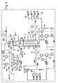
- FIG 10 is a schematic flow diagram of a mixed refrigerant liquefied natural gas plant 40, and also indicates the placement of sensors, for a cascade control system of the prior art.
- the MR LNG plant 40 includes an input feed of natural gas at line 10 flowing through valve 12 to a heat exchanger 14. After cooling in heat exchanger 14, LNG is provided at line 11 as an outlet stream from Joule-Thomson (JT) LNG offtake valve 30.
- Natural gas is cooled in heat exchanger 14 by a heat exchange process employing a closed loop refrigeration cycle with MR.
- MR includes a vapor component MRV and a liquid component MRL.
- the process for liquefaction in an LNG plant and the elements of the LNG plant to implement this process are well known and described in detail U.S. Patent No. 3,763,658, entitled COMBINED CASCADE AND MULTICOMPONENT REFRIGERATION SYSTEM AND METHOD, issued October 9, 1973 to Lee S. Gaumer, Jr. et al..
- the natural gas provided to the heat exchanger 14 through line 10 may be processed first by separation and treating processes including at least one single component refrigeration cycle before being provided to the multicomponent refrigeration portion of the liquefaction process.
- natural gas from a source may be provided at a pressure of between 28 kg/cm 2 a and 70 kg/cm 2 a, with approximately 49 kg/cm 2 a being a typical value. This pressure is determined by the system requirements for separation of heavy hydrocarbons, impurities, water, or other undesirable compounds.
- the natural gas is then cooled to a first temperature, which is typically about ambient temperature (21 degrees centigrade) by first single component heat exchange process.
- a phase separator is used to remove condensed water, and then the natural gas stream is fed to one or more driers to remove additional moisture.
- the dried natural gas stream is then further cooled to a temperature of approximately -1 degrees centigrade in a second heat exchange process and then supplied to scrubbers, or other similar units, to remove benzene and other heavy hydrocarbons.
- the natural gas stream from the scrubbers is then cooled further in a third heat exchange process to approximately -35 degrees centigrade, and is then supplied to the two zone heat exchanger 14 employing a multicomponent refrigeration cycle.
- the liquefaction process occurs as the natural gas flows through a two zone heat exchanger 14. Natural gas from the separation and treating process enters two zone heat exchanger 14 from feed line 10 and passes upwardly through tube circuit 114 from intake valve 12 at a warm bundle 110 of the heat exchanger 14. The natural gas in tube circuit 114 is cooled by a counter flow of MR sprayed downwardly over the tube circuit by spray header 124. The natural gas flows in tube circuit 114 which is contained in warm bundle 110, which is the first zone, within heat exchanger shell 122. The natural gas feed stream passes into cold bundle 112, which is the second zone, and passes upwardly through tube circuit 115 which is cooled by a second counter flow of MR flowing from spray header 126.
- the MR which may a be mixture consisting of nitrogen, methane, ethane and propane, is employed to provide refrigeration within the shell 122 of heat exchanger 114.
- MR may be provided as a liquid and as a vapor within the heat exchanger 14. Heat exchange between the natural gas and the MR is efficiently done by vaporization of MR on the shell side of the heat exchange.
- the multicomponent closed refrigeration cycle portion of the liquefaction process includes two compressor stages, a low pressure compressor stage 34 and a high pressure compressor stage 32.
- the low pressure compressor stage 34 receives the MR from the heat exchanger 14, compresses the MR and then passes the compressed MR to high pressure compressor stage 32.
- the low pressure compressor stage may include a heat exchange process provided by, for example, an aftercooler.
- the high pressure compressor stage 32 compresses and provides the MR at the desired pressure, and may also provide some local heat exchange process through an aftercooler.
- the compressed MR from the low pressure compressor stage 34 is typically about 3.2 kg/cm 2 a, and the compressed MR from the high pressure compressor stage 32 is typically about 49 kg/cm 2 a and provided at a temperature of approximately 77 degrees centigrade.
- the compressed MR from the high pressure compressor stage 32 is passed to another heat exchange process with one or more single component, heat exchangers 128.
- propane is used as the single component refrigerant.
- the MR at 49 kg/cm 2 a is typically cooled to -35 degrees centigrade by the heat exchange process, but the pressure and temperature used in an LNG plant varies and is dependent upon the desired ratio of MRL to MRV for the system.
- the compressed and cooled MR from the heat exchanger 128 is then provided to the separator 42, which separates the MR into the MRV flow at line 13 and MRL flow at line 15.
- the MR must be pre-cooled to a temperature substantially below the freezing point of water, and preferably to a temperature in the order of -18 to -73 degrees centigrade. Consequently, the MRL from separator 42 on line 15 is passed through the warm bundle 110 of heat exchanger 14 to refrigerate the MRL in tube circuit 118.
- the flow rate of the MRL from tube circuit 118 to spray header 124 may be adjusted by Warm JT valve 18.
- MRV from separator 42 on line 13 is also provided to warm bundle 110 of heat exchanger 14 to refrigerate the MRV in tube circuit 116.
- MRV is then provided to the cold bundle 112 in tube circuit 117, and the flow rate of the MRV from tube circuit 117 to spray header 126 may be adjusted by Cold JT valve 16. Cooling of the MRV and MRL in the tube circuits is accomplished in a similar manner to that of the natural gas stream in tube circuits 114 and 115 described previously using counterflowing MR.
- MRL in tube circuit 118 is subcooled in heat exchanger 14 to a temperature in the order of-112 degrees centigrade, and the subcooled MRL is expanded in Warm JT valve 18 to a pressure in the order of 3.5 kg/cm 2 a, whereby a portion flashes to vapor and its temperature drops to approximately -118 degrees centigrade.
- the liquid and flashed vapor are then injected into the warm bundle 110 through spray header 124.
- MRV in tube circuit 116 is also subcooled in heat exchanger 14 where it is condensed, and then provided to second tube circuit 117 in cold bundle 112 wherein the condensed MRV is subcooled to approximately -168 degrees centigrade.
- This subcooled liquid fraction is expanded in Cold JT valve 16 to a pressure in the order of 3.5 kg/cm 2 a, whereby a portion flashes to vapor. The liquid fraction and flashed vapor are then injected into the cold bundle 112 through spray header 126.
- the MR In flowing downwardly over the tube circuits, the MR is vaporized in heat exchange with the natural gas feed stream, as well as in heat exchange with the MRL and MRV flowing upward in the heat exchanger 14. As a result, all the MRL and liquid fraction are recombined in vapor phase at the bottom of the heat exchanger 14, and the vapor is returned to the suction side of low pressure compressor stage 34. MR is returned to the compressors 32 and 34 for compression, and subsequent cooling and separation, through line 120.
- the refrigeration capacity may be determined by setting the speed of the low pressure and high pressure mixed refrigerant (MR) compressor stages 34 and 32, and by adjusting the total inventory and composition of the MR with MR makeup valves 100, 101, 102 and 103; and high pressure separator vent and drain valves (not shown). Compressor speed, makeup valve positions, and vent and drain valves are adjusted by the operators as required.
- MR low pressure and high pressure mixed refrigerant
- the first feedback loop of the prior art controls LNG offtake temperature by cascade control employing a Temperature Indicator Controller (TIC) 26 and Flow Indicator Controller (FIC) 28.
- TIC Temperature Indicator Controller
- FIC Flow Indicator Controller
- the temperature of the LNG output stream from the heat exchanger 14 is measured and compared to a setpoint value SP1 by TIC 26 to provide a desired flow control signal to adjust present temperature to desired temperature.
- FIC 28 measures the present LNG flow and compares this to the desired flow signal from TIC 26, and adjusts the LNG offtake valve(s) 30 accordingly.
- the Warm JT valve 18 is adjusted for feedback control of the ratio of heavy (mixed refrigerant liquid or MRL) to light (mixed refrigerant vapor or MRV) MR.
- the Warm JT valve 18 is adjusted by a Flow Ratio Controller (FRC) 22 which compares the MR flow ratio of MRL to MRV (as measured by Flow Indicators 20), and the MRL/MRV ratio calculated by divider 24 to a setpoint value (SP2) determined offline.
- FRC Flow Ratio Controller
- CRC 39 produces the feedback signal using a setpoint value SP3 also determined offline, and the compressor pressures are read by Pressure Indicators (PIs) 38.
- PIs Pressure Indicators
- An apparatus according to the preamble of claim 27 is, for example, known from U.S. Patent 3,742,721.
- a further embodiment includes varying a value associated with a compressor providing the refrigeration to adjust the temperature value of the LNG outlet stream.
- Another embodiment includes varying a value of mixed refrigerant (MR) providing the refrigeration to adjust the temperature value of the LNG outlet stream.
- MR mixed refrigerant
- FIG. 1 there is shown a two zone heat exchanger 210 comprising a warm zone 212 and a cold zone 214, each of which is outlined by dashed lines in Figure 1.
- the heat exchanger can be any of the types well known in the art which permit of indirect heat exchange between two fluid streams.
- Such heat exchangers can be plate and fin heat exchangers, tube and shell heat exchangers, including coil wound tube heat exchangers, or any other similar devices permitting indirect heat exchange between fluids, such as a natural gas stream and a refrigerant stream.
- the flow of natural gas through the heat exchanger can be upwardly, downwardly or even horizontally.
- the flow through heat exchanger 210 is illustrated in Figure 1 as being horizontal, this should not be taken as a process limitation, since the flow could be vertical and either upward or downward, generally dependent upon the particular type heat exchanger selected.
- natural gas is introduced into heat exchanger 210 via natural gas inlet line 216 and the natural gas passes through the warm zone 212 via heat exchange path 218 and thence through the cold zone 214 via heat exchange path 220 and, finally, liquefied natural gas (LNG) is removed from heat exchanger 210 via LNG outlet line 222, which contains a flow control or pressure reduction device 224.
- LNG liquefied natural gas
- This flow control or pressure reduction device can be any device suitable for controlling flow and/or reducing pressure in the line and can be, for instance, in the form of a turbo expander, a J-T valve or a combination of both, such as, for example, a J-T valve and a turbo expander in parallel, which provides the capability of using either or both the J-T valve and the turbo expander simultaneously.
- FIG. 1 Also shown in Figure 1 is a closed loop refrigeration cycle 226, which is also outlined by dashed lines.
- this closed loop refrigeration cycle comprises refrigerant component inlet lines 228 and 230 to introduce into the refrigeration loop different components of a multi-component or mixed refrigerant. While in Figure 1 only two separate refrigerant component inlet lines are shown, it will be understood by those skilled in the art that, in practice, the multi-component or mixed refrigerant can be comprised of three, four or even five different components, but that for purposes of illustration in the present figure, only two are shown.
- Refrigerant component inlet lines 228 and 230 each contain valves 232 and 234, respectively, to control the amount of individual components being introduced into the refrigeration loop.
- the multi-component or mixed refrigerant is introduced via mixed refrigerant (MR) inlet line 236 to compressor 238.
- MR mixed refrigerant
- the compressed MR from compressor 238 is passed by means of line 240 into cooler 242 wherein the compressed MR is cooled sufficiently to effect at least partial condensation thereof.
- Cooler 242 can be any of the types well known in the art and the compressed MR gas can be cooled against various materials including water, refrigerated water and other hydrocarbons such as heavier hydrocarbons including, for example, propane. While single compression and cooling stages (238 and 242) have been shown, it will be understood by those skilled in the art that multiple compression stages with interstage cooling can readily be employed in this situation. For ease of illustration, only single compression and cooling stages have been shown.
- the partially condensed MR is passed via line 244 into separator 246 wherein it is separated into liquid and vapor phases.
- the liquid phase of the MR (MRL) is withdrawn from separator 246 by means of line 248 and is introduced into the warm zone 212 of heat exchanger 210.
- the vapor phase of the MR (MRV) is removed from separator 246 by means of line 250 and is also introduced into the warm zone 212 of heat exchanger 210.
- the MRV flows through warm zone 212 via heat exchange path 252 cocurrent to the flow of natural gas in heat exchange path 218, also in the warm zone 212. It will be understood, of course, that it is also possible for the flow to be countercurrent in other conformations of a heat exchanger.
- the MRL flows through heat exchange path 254 in the warm zone 212, also cocurrent to the flow of natural gas through heat exchange path 218 in the warm zone of heat exchanger 210.
- the MRV continues to flow through heat exchanger path 256 in the cold end 214 of heat exchanger 210 cocurrent to the flow of natural gas through heat exchanger path 220 in the cold zone 214 of heat exchanger 210.
- the MRV is then withdrawn from heat exchanger 210 by means of line 258 and is passed through flow control or pressure reduction device 260 wherein the pressure of the mixed refrigerant of line 258 is reduced resulting in a reduction in temperature of the MRV.
- device 260 can be any device suitable for controlling flow and/or reducing pressure in the line and can be, for instance, in the form of a turbo expander, a J-T valve or a combination of both, such as, for example, a J-T valve and a turbo expander in parallel, which provides the capability of using either or both the J-T valve and the turbo expander simultaneously.
- the reduced temperature MRV, after leaving device 260 is now reintroduced into heat exchanger 210 via line 262 and is passed through heat exchange path 264 in the cold end 214 of heat exchanger 210.
- the flow through heat exchange path 264 is countercurrent to the flow of mixed refrigerant vapor in heat exchange path 256 and natural gas flow in heat exchange path 220.
- the MRL After having passed through heat exchange path 254 in the warm end 212 of heat exchanger 210, the MRL is withdrawn from heat exchanger 210 by means of line 264 and passed to flow control/pressure reduction device 268 wherein the pressure of the mixed refrigerant liquid is reduced thereby effecting a reduction in temperature of this material.
- device 268 can be any device suitable for controlling flow and/or reducing pressure in the line and can be, for instance, in the form of a turbo expander, a J-T valve or a combination of both, such as, for example, a J-T valve and a turbo expander in parallel, which provides the capability of using either or both the J-T valve and the turbo expander simultaneously.
- the reduced temperature MRL, after leaving device 268, is then reintroduced into heat exchanger 210 by means of line 270 and is combined with the MRV stream leaving heat exchange path 264 and the combined streams from line 270 and heat exchange path 264 are passed through heat exchange path 272 which is in indirect heat exchange relationship with heat exchange paths 218, 252, and 254 in the warm zone 212 of heat exchanger 210 and the combined streams flow through the warm zone 212 in countercurrent flow relative to the flow of natural gas through heat exchange path 218 and the flow of MR through heat exchange paths 252 and 254.
- the combined mixed refrigerant stream passing through heat exchange path 272 is totally vaporized by the time it reaches the end of heat exchange path 272 and the vaporized mixed refrigerant is removed from heat exchanger 210 by means of line 274 and recycled to compressor 238 within the closed loop refrigeration cycle 226.
- heat exchange paths 220, 256 and 264 in the cold zone of heat exchanger 210 are also in indirect heat exchange relationship which each other.
- a temperature sensing device 276 associated with line 222 to measure the temperature of the liquefied natural gas stream flowing in line 222.
- a flow sensing device 278 to measure the flow of liquefied natural gas in line 222.
- the temperature sensing device 276 generates a signal responsive to the temperature of the LNG in line 222 which is used to control the closed loop refrigeration cycle 226 as indicated by dotted line 280 extending from temperature sensing device 276 to the dashed line about closed loop refrigeration cycle 226.
- the flow sensing device 278 also generates a signal responsive to the flow of LNG in line 222 and this signal is passed to flow control device 224 as indicated by line 282.
- the refrigeration of the natural gas can be controlled to adjust the temperature of the LNG outlet stream, while the flow rate of the LNG outlet stream is independently controlled thereby maintaining the flow rate and temperature of the LNG outlet stream at desired levels.
- the signal of line 280 is shown to be transmitted to compressor 238, as indicated by the extension of dotted line 280 and indicated by reference numeral 281, in order to vary a value associated with the compressor providing the refrigeration and thereby adjusting the temperature value of the LNG outlet stream of line 222.
- the compressor value which is varied can be any one or more of compressor speed, guidevane angle or stator blade position, which function(s) to adjust the temperature value to the LNG outlet stream of line 222.
- a predetermined target value based on the constraints defining one of the operating ranges of compressor 238 can be established as indicated by set point 1 device 284 associated with compressor 238 and this particular compressor value can be adjusted to the corresponding set point.
- a value associated with the recirculation of refrigerant in closed loop cycle 226, for example, the flow control or pressure reduction device 268, can be varied. This is indicated by dotted line 285 coming from compressor 238 to flow control/pressure reduction device 268.
- the flow rate of the refrigerant within the closed loop refrigeration cycle 226 can be measured, for example by utilizing a flow sensing device 286 to measure the flow of refrigerant in line 244 to generate a signal responsive to the refrigerant flow rate and feeding this signal as indicated by dotted line 288 to ratio calculator 290.
- a signal representing the flow rate of LNG in line 222 is also fed to ratio calculator 290 by means of the extension of line 282, as indicated by dotted line 283.
- the ratio so formed is adjusted so as to control the operation of the closed loop refrigeration cycle to adjust the temperature value of the LNG outlet stream in line 222.
- the ratio signal from the device is indicated as line 292 running from ratio calculator 290 to closed loop refrigeration cycle 226.
- the flow rate of the refrigerant vapor is measured by a flow sensing device 294 associated with line 250, while the flow rate of the liquid refrigerant stream is measured by flow sensing device 296 associated with line 264.
- a signal representative of the flow rate of the liquid refrigerant is generated by flow sensing device 296 and is transmitted to flow control device 268 as indicated by dotted line 298.
- a signal representative of the vapor refrigerant flow rate generated by flow sensing device 294 is transmitted to flow control device 260 as indicated by dotted line 300.
- the flow of the liquid refrigerant can be adjusted to control the ratio of the flow of liquid refrigerant to the flow of vapor refrigerant.
- the flow of the vapor refrigerant can be adjusted to control the total flow of refrigerant.
- the adjustment of the vapor refrigerant flow results in an adjustment of the overall ratio of refrigerant to LNG flow rate.
- a value of the compressor 238 in closed loop refrigeration cycle 226 is varied further to adjust the temperature value of the LNG outlet stream. This is indicated in Figure 1 by the extension of line 292 coming from ratio calculator 290 to compressor 238.
- the signal generated by flow sensing device 278 and transmitted to flow control/pressure reduction device 224, as indicated by line 282, can be compared to a predetermined value as indicated by set point 2 device 302 and the flow rate in line 222 can be adjusted by means of device 224 in order to make it conform to the predetermined value shown in set point 2 device 302.
- the signal representative of the temperature of the LNG in line 222 is generated by temperature sensing device 276 can also be compared to a predetermined value as indicated by set point 3 device 304 associated with line 280. This can be utilized to adjust the refrigeration provided by closed loop refrigerant cycle 226 or in a particularly embodiment to control one of the variables of compressor 238 thereby to control the temperature of the outlet stream in line 222.
- LNG temperature is controlled by adjusting the refrigeration, while LNG production is controlled independently.
- the LNG production is set in a direct fashion, and the refrigeration is adjusted to match the refrigeration requirements at a given LNG temperature and production. This is an opposite approach to that of the prior art.
- the steps comprise: (a) measuring a temperature and flow rate of the LNG outlet stream at line 11; and (b) varying the refrigeration of the natural gas by vaporization of MR, to adjust the temperature value of the LNG outlet stream at line 11, and (c) adjusting, by LNG offtake valve 30, the rate of the LNG flowing through the liquefaction process from the cold bundle 112 of the heat exchanger 14, thereby, in this way, there is maintained the flow rate and temperature of the LNG outlet stream at predetermined flow value and temperature value setpoints.
- the exemplary embodiments of the present invention include a control system which sets and maintains LNG production at a required production value, and controls LNG temperature by adjusting the refrigeration provided to the natural gas stream (thereby matching the refrigeration to the required production, as opposed to matching the production to the available refrigeration as done in the prior art).
- An exemplary first embodiment of the present invention includes varying a value associated with each compressor 32 and 34 compressing the MR received from the warm bundle 110 in line 120 of the heat exchanger 14, to adjust the temperature value of the LNG outlet stream at line 11.
- the embodiment may employ compressor speed of compressors 32 and 34, for example, as a key manipulated variable (MV) to achieve fast and stable LNG temperature regulation.
- Other compressor variables rather than speed may be key MVs, depending on the type of MR compressors employed, and may be the guidevane angle in a centrifugal compressor or the stator blade angle in an axial compressor.
- a further exemplary embodiment includes varying a mixed refrigerant (MR) value, such as a flow, composition or pressure of the MRV and/or MRL, flowing from headers 124 and 126, to adjust the temperature value of the LNG outlet stream at line 11.
- MR mixed refrigerant
- the second exemplary embodiment employs a ratio of total recirculating refrigerant flow to LNG flow as the key manipulated variable to effectively control the LNG temperature.
- the described embodiments of the liquefaction process include aspects of the coil wound implementation of a two zone heat exchanger in which the natural gas feed stream is passed from the bottom to the top of the heat exchanger unit
- the described embodiments are equally applicable to other types of heat exchangers, such as plate fin heat exchangers mentioned previously.
- the structure and use of the plate fin heat exchanger is described in "Use of plate fin heat exchangers for main cryogenic exchanger units," by M. Onaka, K. Asada, and K. Mitsuhashi, LNG Journal, pp17-19, January-February, 1997.
- the first exemplary embodiment of the present invention used in an LNG plant 40A employs a control system based on feedback control of LNG flow rate, and independent feedback control of the temperature of the LNG production by adjusting compressor speed, and additionally adjusting mixed refrigerant flow to return the compressor speed to a value within a desired operating range.
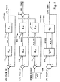
- FIG. 2 is a high level block diagram illustrating the basic feedback control scheme for the exemplary speed control-based embodiment of the present invention.
- a first feedback loop 201 controls the flow rate of LNG through a first manipulated variable (MV), such as LNG offtake valve position
- a second feedback loop 202 controls the temperature of the LNG production using a compressor value, such as speed, as a second MV
- a third feedback loop 203 also affects temperature of the LNG by controlling a flow of refrigerant through the system using a third MV such as Warm or Cold JT valve position. Adjustment of this third MV may also be used to maintain the compressor value within a desired operating range by adjusting the refrigeration of the closed loop refrigeration cycle to move LNG temperature in the same direction as that accomplished by compressor value adjustment.
- MV manipulated variable
- Adjustment of the compressor value has the following effect on the process.
- a decrease in the pressure of the refrigerant at the inlet of the compressor and in line 120 (of Figure 1) occurs. Consequently, the pressure, and, therefore, the temperature, at the shell side of the heat exchanger decreases, causing an increase in heat transfer, and therefore, in the refrigeration, provided to the natural gas flowing in the heat exchanger 14.
- a decrease in speed has an opposite effect.
- a first loop controls the LNG flow rate about a setpoint value
- a second loop independently controls the LNG temperature about a setpoint value.
- the second control loop involves two MVs: a compressor MV, such as speed or equivalent compressor value, with a fast temperature response (which is desirable), but with a relatively weak steady-state gain (not as desirable); and a second MV, such as Warm JT valve position, with a relatively stronger steady-state gain (which is desirable) but with a slower temperature response (not as desirable).
- the use of two MVs for the second control objective improves controllability of the process by using the best features of each MV to compensate for the weaknesses of each MV.
- the first feedback control loop 201 LNG flow is controlled in order to change and maintain the LNG outlet stream (LNG production) to a desired LNG flow rate. This adjustment may be accomplished by, for example, adjusting the position of the LNG offtake valve 30 ( Figure 3).
- the first feedback loop includes an LNG flow setpoint value which is determined offline or online, and may be determined, for example, from a production schedule for the particular plant.
- Plant process 216 models a dynamic response of LNG flow rate to changes in the LNG offtake valve position through process transfer function g11.
- a flow rate controller 210 adjusts LNG flow rate based upon an error signal indicating a variation of the LNG flow rate with respect to a setpoint value.
- Flow rate controller 210 offsets these variations in LNG flow rate with respect to the setpoint value by control transfer function g C1 derived from the plant process transfer function g 11 .
- the error signal is a combination based upon the difference between the actual value of the variable controlled and a setpoint value, which for feedback loop 201 is actual measured LNG flow rate and the desired LNG flow rate setpoint.
- the error signal may be discrete or continuous, and the form of the error signal is dependent upon the type of controller used.
- feedback control the adjustment of an MV based upon the error signal corresponding to the variations of the controlled variable about a setpoint.
- a simple controller which may be implemented is the Proportional Integral Derivative (PID) controller.
- the error signal may be the combination of the difference (e(t)), an integrated difference and a derivative of the difference between the setpoint and measured value.
- the PID controller output signal y PID (t) to adjust the MV is given by equation (1), where K is a proportional gain, and F, 1/ ⁇ i and ⁇ d are constants:
- the controller may be more complex, such as an internal model controller (IMC).
- IMC internal model controller
- the output signal y IMC (t 0 ) to adjust the MV is a more general function of the present and past values of the error signal and is given in general form by equation (2) using discrete sample notation:
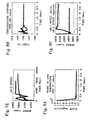
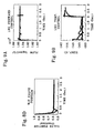
- the method of determining the system process transfer functions g 11 , g 22 , g 23 , and hence the control transfer functions g C1 , g C2 , and g C3 is as follows:
- the open loop system i.e. the LNG liquefaction process with no control loop
- a step test by applying a step function for the variable under study, letting the system run to a steady-state, and collecting data for all system parameters.
- the system may be the plant itself in operation, or a full non-linear dynamic simulation of the plant. For example, if one wishes to find the LNG flow rate transfer function g 11 , the process would be subjected to a step function increase in LNG offtake valve position and resulting LNG flow rate changes recorded.
- tuning constants for the controller model transfer functions may be adjusted based upon dynamic non-linear system simulation. Such simulation subjects the running closed loop control system to a wide variety of operating conditions, while comparing the operation of simulated parameters with known operation of the parameters in the LNG plant.
- second feedback loop 202 includes an LNG temperature setpoint value which is determined offline, and is a function of process requirements. Consequently, the second feedback loop 202 is used to maintain the LNG outlet stream at or near a desired production temperature value. For this second feedback loop, this may be accomplished by, for example, adjusting compressor speed to control LNG outlet stream temperature.
- Other compressor values relating to a compressor's capacity such as guidevane angle of a mixed refrigerant centrifugal compressor or stator blade position of a mixed refrigerant axial compressor, may be used as the MV of the compressor.
- the dynamics of the LNG plant process may be modeled by a process transfer function, and the plant process 218 models the dynamic process of LNG temperature to changes in refrigeration provided by changes in compressor value through process transfer function g 22 .
- a Compressor Controller 212 adjusts LNG temperature using feedback control by adjusting a compressor value, such as speed, based upon an error signal derived from the difference between the LNG temperature setpoint and the actual measured LNG outlet stream temperature.
- the Compressor Controller 212 offsets variations in LNG temperature by control transfer function g C2 derived from the process transfer function g 22 .
- the third feedback loop 203 of Figure 2 includes a compressor setpoint value of speed or equivalent value which is determined offline and is related to a value within the desired operating range of the compressor, and may also be determined, for example, from compressor characteristics based on efficiency.
- the third feedback loop is a special form of cascade control known as input resetting, which takes advantage of the availability of an extra MV, such as the position of the Warm JT valve in the exemplary embodiment, to control a single objective, such as the LNG temperature.
- the techniques of input resetting are known in the art and described, for example, at page 416 in Multivariable Feedback Control, Analysis and Design, by NASAd Skogestad and Ian Postlethwaithe (J. Wiley and Sons, 1996).
- the controller 214 offsets variations in LNG temperature by control transfer function g C3 derived from the process transfer function g 23 .
- Moving Warm JT valve 18 causes a refrigeration adjustment that has an effect on LNG temperature in the same direction as the compressor speed.
- This third feedback loop 203 operates in tandem with the second feedback loop 202, and allows the compressor speed to return to its original target value.
- a single, multivariable controller may be used to implement feedback control of LNG temperature.
- Multivariable feedback loop 204 receives an error signal as a combination of the measured LNG temperature and the LNG temperature setpoint value.
- Plant process transfer function g 2 models the response of the LNG temperature to simultaneous changes in compressor speed and Warm JT valve position.
- Multivariable controller 222 then simultaneously adjusts compressor speed and Warm JT valve position by control transfer function G C 25 to move the LNG temperature toward the desired setpoint value.
- FIG 3 is a schematic flow diagram of a typical mixed refrigerant liquefied natural gas plant indicating the placement of sensors and controllers for a speed-based control system implementing the control system as illustrated in Figure 2.
- the first feedback loop 201 of Figure 2 is implemented by the Flow Indicator Controller (FIC) 28, which corresponds to the Flow Rate Controller 210 of Figure 2, and LNG offtake valve 30.
- FIC 28 measures the LNG outlet stream flow rate, and receives the LNG flow setpoint SP10. Based on an error signal from a difference of the measured outlet stream flow and setpoint SP10, the position of the LNG offtake valve 30 is opened or closed to maintain the LNG outlet stream at the desired flow rate.
- FIC Flow Indicator Controller
- the second feedback loop 202 of Figure 2 is implemented by the Temperature Indicator Controller (TIC) 26 and compressor speed controllers 36, which together correspond to the Compressor Controller 212 of Figure 2.
- TIC 26 measures the actual LNG outlet stream temperature and receives the LNG temperature setpoint SP11. Based on an error signal being a combination of the measured outlet stream temperature and the setpoint SP11, the TIC 26 provides a signal to compressor signal controllers 36 which adjust the compressor speed. As previously indicated, rather than compressor speed, the centrifugal compressor's guidevane angle or axial compressors stator blade position would be changed in other implementations.
- controllers such as the FIC 28 and the TIC 26 are readily available and may be implemented as PID controllers These controllers require the user to provide the controller gains, as well as tuning parameters, as given by equation (1). This information may be determined using model based controller design techniques described previously.
- the third feedback loop is implemented by the speed indicator controller (SIC) 53, corresponding to the controller 214 of Figure 2, and Warm JT valve 18.
- the SIC 53 adjusts the refrigeration in the following manner for a system using compressor speed as the compressor value.
- the SIC 53 receives the compressor speed signal (which gives the current compressor speed) from the compressor speed controllers 36 and the speed target value (which may be calculated off-line or may be determined from the optimal speed for the current refrigerant mass flow for the closed loop refrigeration cycle), and then SIC 53 calculates a control signal based on an error signal which is a combination of the actual compressor speed and the desired speed target value. Consequently, the SIC 53 adjusts the position of Warm JT valve 18 in response to the control signal to return the compressor speed to the desired speed target value.
- the second control objective is implemented as two parts which both control temperature of the LNG outlet stream.
- the use of two MVs to control LNG temperature helps controllability and in addition allows operation of the LNG control system within constraints imposed by the particular implementation of the LNG plant.
- the compressor value of the feedback loop 202 such as speed
- the extra MV is beneficial. This is to prevent the compressor from being operated at a speed outside of the preferred operating range of the compressor. For example, operating at too a high speed may be very efficient but may damage the compressor components, but operating at too low a speed may cause compressor surge, where mass flows through the compressor reverse.
- one embodiment of the present invention may include the above described third feedback loop, shown as 203 of Figure 2, to adjust refrigeration provided to the natural gas flowing through the heat exchanger system by adjusting the position of the Warm JT valve 18 to assist the compressor speed in its task.
- further adjustments including adjustment of LNG flow rate and LNG temperature set points, may be used to return operation of the compressors and position of Warm JT valves 18 to within a desired range.
- the setpoint value for the temperature is determined from the desired operating characteristics of the plant. For example, in an LNG plant such as is shown in Figure 2 employing a flash cycle process, if LNG production reaches a temperature warmer than about -146 degrees centigrade, the LNG production will contain an LNG vapor component which must be flared off by equipment downstream of the heat exchanger, resulting in an unnecessary loss of natural gas. However, if the LNG production reaches a temperature colder than about -151 degrees centigrade, the LNG production will not contain enough vapor component for fueling compressors downstream of the heat exchanger. Such downstream compressors use the natural gas of vapor component as a fuel source to power the compressors, and the operating characteristics of the downstream compressors will determine the low end operating temperature. Therefore, desired operating temperature setpoint of LNG production may be selected within this temperature range.
- the desired temperature setpoint is determined by the characteristics of the downstream storage tank (if temperature is too warm, LNG vapor flashing occurs, but if the temperature is too cold, the liquefaction process is inefficient).
- a further control loop can be used to adjust a position of the Cold JT valve 16 to control MRV flow and a MRV flow setpoint may be adjusted to control MRL/MRV flow ratio.
- a Flow Ratio Controller (FRC) 51 receives a MRL/MRV flow ratio from flow ratio detector (FR) 52 and compares the MRL/MRV flow ratio to a predetermined setpoint value. Based on an error signal formed as a combination of actual and desired MRL/MRV flow ratio, a control signal is provided to the Cold JT valve 16 to adjust the valve position.
- This additional feedback loop is needed to maintain a proper balance of flows within the heat exchanger to prevent, for example, the return temperature of line 120 from getting too cold, which may damage equipment.
- the Warm JT valve 18 and Cold JT valve 16 may each reach the fully open or fully closed positions, the mixed refrigerant ratio may be outside of a target value, or the mixed refrigerant (MRV or MRL) temperatures outside of acceptable ranges.
- MRL mixed refrigerant
- the system may require: the compressor speed target be increased or decreased if the Warm JT valve 18 or the Cold JT valve 16 reach an upper or lower constraint, the MRL/MRV flow ratio be decreased if the temperature of MR exiting the heat exchanger at the warm bundle 110 (suction to first compressor) is too cold, and compressor antisurge control be achieved by opening the compressor recycle valve(s) when a predetermined distance to surge is reached.
- Further constraints may be based on mixed refrigerant compressor discharge pressure or mixed refrigerant compressor power. Satisfying these constraints may be accomplished by either operator intervention or by a computer monitoring and control system separate from the described exemplary embodiment.
- feedforward calculations using measured values of the current MR may be used to determine a new compressor speed target value based upon the mass of refrigerant flowing through the system.
- Figure 2 shows this additional Speed Feedforward block 205 providing the speed target setpoint value, and the calculations are described in more detail below with reference to the refrigerant recirculation-based control method.
- values of a table or graph showing optimal compressor speed for a given mixed refrigerant mass flow rate may be used to adjust compressor speed target value.
- Optimal compressor values for these purposes may be based on an independent variable, for example, compressor efficiency.
- Target values for the MR compressor speed, or mixed refrigerant centrifugal compressor guidevane angle or mixed refrigerant axial compressor stator blade angle may be determined using an off-line or on-line steady-state optimization computer program or calculation receiving a number of variables or factors including, but not limited to: (a) LNG production target; (b) natural gas feed conditions; (c) mixed refrigerant inventory; (d) mixed refrigerant composition; (e) operating pressures; (f) available power; (g) equipment design; (h) compressor characteristics; and/or (i) external conditions.
- Target values for the MRL/MRV flow ratio may be determined by using an off-line or on-line steady-state optimization computer program or calculation receiving a number of variables or factors including and not limited to: (a) LNG production target; (b) natural gas feed conditions; (c) mixed refrigerant inventory; (d) mixed refrigerant composition; (e) operating pressures; (f) available power; (g) equipment design; (h) compressor characteristics; and/or (i) external conditions.
- the second exemplary embodiment of the present invention employs a refrigerant recirculation based control system employing feedforward and feedback control to adjust the temperature of the LNG production by changing MRL and MRV flow rates (to change Total MR flow), MRL/MRV flow ratio and then Total MR flow/LNG flow ratio, and then adjusting a compressor MV such as speed to a value within an optimal operating range of the compressor for the current MR mass flow.
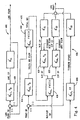
- Figure 4 is a high level block diagram illustrating the basic control feedback and feedforward loops for the exemplary recirculation-based embodiment of the present invention.
- the exemplary embodiment includes three main control sections: a first feedback loop 401 controls the flow rate of LNG production; a second feedback and feedforward section 402 controls the temperature of the LNG production; and a third feedforward section 403 adjusts compressor speed to maintain the compressor speed within an optimal range based upon the mass of refrigerant (the total MR) flowing through the closed loop refrigeration cycle.
- a first feedback loop 401 controls the flow rate of LNG production
- a second feedback and feedforward section 402 controls the temperature of the LNG production
- a third feedforward section 403 adjusts compressor speed to maintain the compressor speed within an optimal range based upon the mass of refrigerant (the total MR) flowing through the closed loop refrigeration cycle.
- LNG flow is controlled in order to change and maintain the LNG outlet stream (LNG production) to a desired production LNG flow rate, and may be accomplished by, for example, adjusting the position of the LNG offtake valve 30 ( Figure 5).
- the first feedback loop includes an LNG flow setpoint value which is determined offline, and may be determined, for example, by production requirements.
- the dynamics of the LNG plant process may be modeled by transfer functions and the techniques described with reference to the compressor speed based control method may be used.
- Plant process of 401 models dynamic process of LNG flow rate to changes in LNG offtake valve position through transfer function g 11 '.
- a flow rate controller 410 adjusts LNG flow rate, based upon an error signal formed from a combination of the LNG flow rate setpoint and the actual measured LNG flow rate.
- the flow rate controller 410 offsets variations in LNG flow rate by control transfer function g C1 ' which may be derived from the process transfer function g 11 '.
- the LNG flow setpoint value, process transfer function g 11 ' and control transfer function g C1 ' may be the same as the LNG flow rate setpoint, process transfer function g11 and control transfer function g C1 for the compressor speed-based control method shown in 201 of Figure 2.
- the second section 402 is an LNG temperature feedback/feedforward control system which maintains the LNG temperature about a setpoint value using an LNG Temperature setpoint value and a ratio of Warm IT valve and Cold JT valve setpoints. Control of the LNG temperature is done by adjustment of the desired target value of the ratio of total MR flow rate to LNG flow rate.
- a current measured LNG outlet stream temperature is compared to an LNG Temperature setpoint value to provide an error signal to MR Change Controller 414 which determines by control transfer function g C2 ' an incremental change in mixed refrigerant flow rate, defined as a Delta MR flow rate value, to offset the difference in LNG outlet temperature.
- the Total MR flow rate and a MRL/MRV ratio setpoint are used to adjust the MRL flow rate and MRV flow rate of the MR recirculating through the process.
- MRL flow controller 419 which receives the MRL flow rate setpoint value and the current measured MRL flow rate and forms an error signal as a combination of these MRL flow rate values, and through control transfer function g C5 ' adjusts the MRL flow rate, for example, by adjusting the position of Warm JT valve 18.
- the second control loop employs MRV flow controller 420 which receives the MRV flow rate setpoint value and the current measured MRV flow rate and forms an error signal as combination of these MRV flow rate values, and through control transfer function g C6 ' adjusts the MRV flow rate, for example, by adjusting the position of Cold JT valve 16.
- the control transfer functions g C5 ' and g C6 ' may be determined from the open loop modeled LNG plant process transfer functions g 21 ' and g 22 ' which relate the LNG plant process to the MRL and MRV flow rate effect on the LNG outlet stream temperature.
- Figure 5 is a schematic flow diagram of a typical MR LNG plant 40B indicating the placement of sensors and controllers for a recirculation-based control system implementing the control system as illustrated in Figure 4.
- the first control loop 401 of the recirculation based control system of Figure 4 maintains the LNG outlet stream at a predetermined flow rate given by setpoint SP20, and the first control loop includes Flow Indicator Controller 28, and LNG offtake valve 30, and operates in a manner similar to the first control loop of the compressor speed-based system.
- FIC 28 measures the LNG outlet stream flow rate, and receives the LNG flow setpoint SP20. Based on an error signal formed as a combination of the measured outlet stream flow and setpoint SP20, the position of the LNG offtake valve 30 is opened or closed to maintain the LNG outlet stream at the desired flow rate.
- the second feedforward/feedback control loop 402 of Figure 4 of the recirculation based control system is shown in Figure 5 and includes Temperature Indicator Controller (TIC) 26, Total MR Flow Rate Controller TMR FRC 64, MRL and MRV Flow Rate Controller (MR L/V FRC) 66, Feed Forward Logic (FFL) 68, MRV Flow Indicator Controller (MRV FIC) 72 for adjusting MRV flow by adjustment of Cold JT Valve 16, and MRL Flow Indicator Controller (MRL FIC) 70 for adjusting MRL flow by adjustment of Warm JT Valve 18.
- TIC Temperature Indicator Controller
- TMR FRC Total MR Flow Rate Controller
- MRL and MRV Flow Rate Controller MR L/V FRC
- FTL Feed Forward Logic
- MRL Flow Indicator Controller
- MRL FIC MRL Flow Indicator Controller
- TIC 26 receives an LNG outlet stream setpoint value SP21 corresponding to the desired outlet stream temperature of the LNG, and also measures the current temperature of the LNG outlet stream. Based on an error signal, which is related to the difference between the current temperature and the setpoint value SP21, a TIC 26 provides a temperature adjustment control signal which indicates the Delta MR flow necessary to adjust LNG temperature, and this control signal is provided to the TMR FRC 64, which corresponds to the Total MR Controller 416 of Figure 4. TMR FRC 64 also receives the setpoint value SP20 corresponding to the desired LNG outlet stream flow rate. Using equation (1), TMR FRC 64 provides the FFL 68 a desired total MR flow rate.
- MRL and MRV Flow Ratio Controller (MR L/V FRC) 66 which corresponds to the MRL/MRV Ratio Controller 418 of Figure 4, receives a MRL/MRV flow rate ratio setpoint value SP22 and the current MR flow rate from TMR FRC 64, and provides new MRL and MRV flow rate setpoints, which are received and converted into setpoint values SP23 and SP24 respectively by FFL 68 using the equations (2) and (3).
- MRL controller 419 and MRV Controller 420 are implemented by the MRV Flow Indicator Controller (MRV FIC) 72 for adjusting MRV flow based upon new setpoint value SP23 by adjustment of Cold JT Valve 16, and MRL Flow Indicator Controller (MRL FIC) 70 for adjusting MRL flow based upon new setpoint value SP24 by adjustment of Warm JT Valve 18.
- MRV FIC MRV Flow Indicator Controller
- MRL FIC MRL Flow Indicator Controller
- control of the MRL flow rate to a desired setpoint value is provided by feedback loop adjusting the position of Warm JT Valve 18, and control of the MRV flowrate to a desired setpoint value is done by feedback via adjustment of the Cold JT valve 16.
- the desired target setpoint value SP22 for the ratio of mixed refrigerant liquid flow to mixed refrigerant vapor (MRL/MRV) flow rate is maintained by adjusting the setpoint value SP24 of the MRL flowrate.
- the ratio of total MR flow rate to LNG flow rate is attained by adjusting the setpoint value SP23 of the MRV flowrate. In this manner, the LNG outlet temperature is maintained near the setpoint value SP21 and the LNG outlet stream flow rate is maintained near the setpoint value SP20.
- an embodiment of the present invention may include a third feedforward section 403 having control process 422 with control transfer function g C7 ', as shown Figure 4, which adjusts the compressor speed based on the mass of total refrigerant flowing through the compressor system.
- the output compressor speed provided through gain g C7 ' affects LNG outlet temperature through process transfer function g 23 '.
- the feedforward section 403 of Figure 4 may be implemented by Feedforward controllers (FF) 62 and Speed Controller pair 36 and 38 for each respective compressor stage (i.e. low pressure compressor 34 and high pressure compressor 32).
- FF Feedforward controllers
- Speed Controller pair 36 and 38 for each respective compressor stage (i.e. low pressure compressor 34 and high pressure compressor 32).
- FF 62 measures the received MR mass flow.
- the FF 62 then provides a compressor value to the speed controller 36 and 38 to adjust operation of the compressor, the respective low pressure compressor 34 or high pressure compressor 32, based on available information of compressor efficiency. Such adjustment may further be based on performance curves derived from compressor performance as a function of mass flow rate of MR.
- speeds of the mixed refrigerant low pressure and high pressure compressors 34 and 32 are additionally and separately adjusted by FF 62.
- Each FF 62 measures the current mixed refrigerant flow rate for the respective compressor and sends speed control signal to the respective compressor speed controller 36 or 38 based upon a desired mass flow rate for low pressure compressor 34 or high pressure compressor 32 to ensure maximum compressor efficiency.
- Compressor speed controller 36 or 38 then sets the respective compressor speed accordingly. In plants where speed is fixed or cannot be changed for adequate control, moving an equivalent variable is possible. For example, guidevane angles of one or more mixed refrigerant centrifugal compressors may be adjusted as a function of the current mass flow rate for each compressor to ensure maximum compressor efficiency. Also, stator blade angles of one or more mixed refrigerant axial compressors may be adjusted as a function of the current mass flow rate for each compressor to ensure maximum compressor efficiency.
- Compressor antisurge control is achieved by opening the compressor recycle valve(s) when a predetermined compressor surge level is reached. This may be accomplished by, for example, operator intervention or a dedicated anti-surge controller.
- Constraint control of the temperature of the recirculating refrigerant at the warm bundle 110 of the main cryogenic heat exchanger may be accomplished by determining an appropriate low temperature constraint value for temperature at the warm bundle 110 through, for example, operational requirements of the system; and then measuring the warm end temperature and comparing the measured warm end temperature to the constraint value. If the temperature is less than the constraint value, the desired target value of the MRL/MRV flow ratio is reduced.
- Target values for the mixed refrigerant compressor speed, or mixed refrigerant centrifugal compressor guidevane angle or mixed refrigerant axial compressor stator blade angle are determined using an off-line or on-line steady-state optimization computer program or calculation receiving a number of variables or factors including, but not limited to: (a) mixed refrigerant composition; (b) operating pressures; (c) available power; (d) equipment design; (e) compressor characteristics; and/or (f) external conditions.
- Target values for the MRL to MRV flow ratio are determined by using an off-line or on-line steady-state optimization computer program or calculation receiving a number of variables or factors including and not limited to: (a) LNG production target; (b) natural gas feed conditions; (c) mixed refrigerant inventory; (d) mixed refrigerant composition; (e) operating pressures; (f) available power; (g) equipment design; (h) compressor characteristics; and/or (i) external conditions.
- Results of a dynamic simulation of an LNG plant employing the control systems and rigorous non-linear models of the LNG process may be analyzed in order to compare performance of the LNG plant control methods as shown in Figure 3 and Figure 5.
- the designed control system transfer functions and the linear models used to define the process transfer functions may be determined as described previously.
- the performance of the speed-based control method and the recirculation-based control method are demonstrated using a rigorous, non-linear model of a typical two-bundle baseload LNG plant.
- the results are from closed-loop dynamic simulations of the MCHE/MCR loop section.
- Table 1 lists system parameters, including key process variables and the corresponding initial steady-state values, for the non-linear model used in the exemplary dynamic simulation.
- Table 1 represent a "snap-shot" in time of the LNG plant being modeled.
- MODEL VARIABLES FOR LNG PLANT MODEL TAG PLANT SIMULATION %ERROR VALVE POSITION LNG offtake E5TIC01A MV 78 % 90.62 % 16.18 Cold JT E5PRIC15 MV 82 % 90.075 % 9.85 Warm JT E5FIC002 MV 83 % 97.461 % 17.42 COMPRESSOR SPEED 4K-2 E4SI023A set 4556 rpm 4556 rpm 0.00 4K-3 E4SI028A set 4499 rpm 4499 rpm 0.00 FLOWS LNG product after flash tank E5FI006A 715 m3/h m3/h LNG offtake from MHE calc.
- Table 1 are steady-state values at a particular instant of time. As known in the art, each particular LNG plant has different operating characteristics, and a dynamic simulation of an LNG plant using a non-linear model would be customized for the particular LNG plant. Consequently, the comparison, control objectives and corresponding steady-state operating values of Table 1 are exemplary.
- Control Objectives Control Setpoint Allowed range Variable LNG 18110 kmol/h +/-2% flow LNG temperature -146 C +/- 2.5 C MV Constraints MV Max Min Rate of Change LNG, CJT, WJT 1.16 0 4K-2 Speed 4900 rpm 3500 rpm ⁇ 5 rpm/sec 4K-3 Speed 4900 rpm 3500 rpm ⁇ 5 rpm/sec Output constraints Variable Max constraint Min constraint Discharge pressure 51 kg/cm2a Shell temp, warm end -38 C Distance to surge 8 % away from surge
- Table 2 gives exemplary maxima, minima and ranges for control objectives, and also MV and output constraints. In order to relate these objectives to other systems, a brief description follows of how these objectives are determined.
- the maximum value of LNG plant production is determined by the particular plant and natural gas supply, and the minimum value is zero, corresponding to a shut down of the plant. Consequently, for LNG flow rate, the desired flow rate is determined by LNG plant operators and plant production schedule.
- the exemplary control objective of +/- 2% change relates to typical values currently used for flow control in LNG plants. Larger values for a range of LNG flow rate change may be used up to the maximum and minimum values, but the efficiency of the LNG plant may be affected.
- the minimum range will be determined by the accuracy of the measurement devices, the accuracy of the control element, and the characteristics of the transient response of the LNG plant process. Consequently, the minimum range may be found from a study of the LNG plant or by simulation.
- the operating range of the Warm JT, Cold JT and LNG offtake valves is between fully open and fully closed, and these are allowed to move freely within this range.
- the discharge pressure is determined by the design pressure of the heat exchange circuit
- the shell temperature at the warm end is determined by the minimum temperature before damaging downstream equipment, which may be approximately -50 degrees centigrade, with -38 degrees centigrade typically used in LNG plant operation.
- the distance to surge is set at a reasonable value to prevent damage to the compressors.
- the control transfer functions have the following tuning parameters: for g C1 (Control of LNG flow rate), the proportional gain is 10 -5 1/(kgmoles/hr), and integral time ⁇ I is 2 sec.; and for g C2 ( Control of LNG Temperature), the proportional gain is -500 rpm/ C, and the integral time ⁇ I is 295 sec.
- a model-based control algorithm is used, as described previously. This includes a first order filter, and the filter time constant is used as the adjustable tuning parameter. The time constant is related to the desired speed of the response of the closed-loop system, and may be limited by stability considerations.
- the proportional gain constants have the following tuning parameters: for g C1 ' (Control of LNG flow rate), the proportional gain is 10 -5 1/(kg-moles/hr), and the integral time ⁇ I is 2 sec.; for g C2 ' (Control of LNG Temperature), the proportional gain is 600 , and the integral time ⁇ I is 2500 sec.; for g C3 ', the gain is determined from the model of the process derived from the open loop response; for g C4 ', the gain is determined from the model of the process derived from the open loop response; for g C5 ' (Control of Warm JT valve flow rate), the proportional gain is 10 -5 1/(kg-moles/hr), and the integral time ⁇ I is 1 sec.; for g C6 ' (Control of Cold JT valve flow rate) the proportional gain is 3.528 X 10 -6 1/(kg-moles
- Results are presented for both the speed-based control method and the recirculation-based control method, and compared when appropriate, to the desired setpoint values.
- the results of the simulation scenarios are illustrated in Figures 6 through 9, which are given as the behavior of various variables under study as a function of time.
- the illustrated simulations of Figures 6 through 9 show that both the compressor speed-based method (marked (a)) and the recirculation-based method (marked (b)) adequately satisfy the control objectives of the various scenarios.
- Figures 6A through 6D illustrate the performance of the compressor speed based and recirculation based control methods using a 4% step reduction in LNG flow setpoint scenario.
- Figure 6A is a graph illustrating control of LNG flow rate versus time
- Figure 6B is a graph illustrating control of LNG temperature versus time
- Figure 6C is a graph illustrating control of compressor speed versus time
- Figure 6D is a graph illustrating movement of warm IT valve position versus time for the 4% step reduction in LNG flow setpoint scenario.
- Figure 6A and Figure 6B illustrate that tight control of flow and temperature respectively is achieved with both the compressor-speed based control method and the recirculation based control method.
- Figure 6C shows the compressor speed as a function of time. Both control methods show a fast initial reduction in the speed to correct for the initial temperature reduction due to lower heat load.
- the speed-based strategy is designed to reset the speed back to its original target value (4550 rpm for this example), and does so by employing the Warm JT valve position as an additional MV. Reducing the opening of the Warm JT valve has an effect on the LNG temperature that is in the same direction, although slower than, that of the compressor speed.
- Figures 7A through 7E illustrate the performance of the compressor speed based and recirculation based control methods using a 4% step increase in LNG flow setpoint scenario.
- Figure 7A is a graph illustrating control of LNG flow rate versus time
- Figure 7B is a graph illustrating control of LNG temperature versus time
- Figure 7C is a graph illustrating warm JT valve position and cold JT position versus time
- Figure 7D is a graph illustrating shell temperature of a heat exchanger versus time
- Figure 7E is a graph illustrating control of compressor speed versus time for a 4% step increase in LNG flow setpoint scenario.
- FIG. 7A through 7E The performance as illustrated in Figures 7A through 7E shows that both LNG flow and temperature are also controlled in this scenario well within the required range of Table 2, although the temperature response is slower for the recirculation-based method.
- the Figures 7A through 7E illustrate some of the constraint control actions for this scenario.
- the initial steady-state LNG outlet stream is already a high production value, and the LNG flow rate setpoint is further increased by 4%.
- the Warm JT valve position does not hit its constraint (defined at 1.16 in Table 2), but the Cold JT valve does reach a constraint. In the case of the speed-based method, the Cold JT valve position is increased as one measure to prevent the heat exchanger shell warm end from getting too cold.
- the position of Cold JT valve 16 reaches the constraint, but the control methods still manage to control the shell warm bundle close to its constraint.
- the control methods of this example increase the speed target value from 4550 rpm for the compressor to about 4850 rpm.
- Figures 8A through 8D illustrate the performance of the compressor speed based and recirculation based control methods for a 35% ramp reduction, at 1% per minute, in LNG flow setpoint scenario.
- Figure 8A is a graph illustrating control of LNG flow rate versus time
- Figure 8B is a graph illustrating control of LNG temperature versus time
- Figure 8C is a graph illustrating control of low pressure and high pressure compressor speed versus time
- Figure 8D is a graph illustrating movement of warm JT valve position versus time for a 35% ramp reduction, at 1% per minute, in LNG flow setpoint scenario.
- Figures 8A through 8D illustrate that control of LNG flow rate and temperature by the exemplary control methods is well within the requirements given in Table 2.
- Figure 8C shows compressor speeds for this example, and shows that in the speed-based strategy, once the production flow rate ramp-down is nearly complete, and with the assistance of adjustment of the Warm JT valve position, the compressors return to their original speed. Consequently, the compressors have enough speed operating range for a subsequent ramp-down (or ramp-up) in LNG flow rate.
- the compressors are nearing compressor surge conditions. For this situation, surge conditions are prevented by opening recycle valves for each compressor once a distance to surge falls below 8%.
- Figure 9A is a graph illustrating control of LNG flow rate versus time
- Figure 9B is a graph illustrating control of LNG temperature versus time, for a servo change and disturbance rejection scenario. As is shown, both the compressor speed-based and recirculation based control methods provide adequate control of LNG flow rate and temperature.
Description
- This invention relates to the field of control systems for production of liquefied natural gas (LNG), and more specifically, to a method and an apparatus which control LNG production and LNG temperature.
- Systems for the liquefaction of natural gas using a multicomponent refrigerant are in use throughout the world. Multicomponent refrigerant process and cryogenic equipment are used throughout the industry, and control of the LNG production process is important to operate a plant efficiently, especially when attempting to extract incremental production from a fixed plant or when attempting to adjust to external process disturbances. Many baseload LNG plants in the world employing a mixed refrigerant process are manually controlled or controlled to satisfy only a subset of the key control objectives.
- Simultaneous and independent control of both LNG production rate and temperature is important for LNG plant operation. By fixing and maintaining the LNG production rate, plant operators can adequately plan and achieve desired production levels as required by the product shipping schedule. Maintaining the temperature of the LNG exiting the main cryogenic heat exchanger within a specified range is important for downstream processing and the prevention of downstream equipment problems. Once regulatory control is achieved for the key variables, optimization strategies can be properly implemented. However, if regulatory control is not adequate, even standard day to day operation is adversely affected.
- One control system of the prior art is based on the strategy of U.S. Patent 4,809,154, entitled AUTOMATED CONTROL SYSTEM FOR A MULTICOMPONENT REFRIGERATION SYSTEM, issued February 28, 1989 to Charles Newton to control the main cryogenic heat exchanger/mixed refrigerant loop system. The recommended control strategy in U.S. Patent No. 4,809,154 has as its objective to achieve the highest production per unit of energy consumed. The refrigeration capacity is determined by setting the speed of low pressure and high pressure multicomponent, or mixed, refrigerant (MR) compressors, and by adjusting the total inventory and composition of the MR with the MR makeup valves and the high pressure separator vent and drain valves. Compressor speed, makeup valves, and vent and drain valves are adjusted by the operators as required, but they are not part of the automatic regulatory control strategy. The regulatory control strategy consists of three main feedback loops. A cold JT valve is adjusted for feedback control of the pressure ratio across the MR compressors. A warm JT valve is adjusted for feedback control of the ratio of heavy (mixed refrigerant liquid or MRL) to light (mixed refrigerant vapor or MRV) MR. Control of the LNG offtake temperature is done by means of the LNG offtake valve(s).
- Figure 10 is a schematic flow diagram of a mixed refrigerant liquefied natural gas plant 40, and also indicates the placement of sensors, for a cascade control system of the prior art. As shown in Figure 10, the MR LNG plant 40 includes an input feed of natural gas at
line 10 flowing throughvalve 12 to aheat exchanger 14. After cooling inheat exchanger 14, LNG is provided atline 11 as an outlet stream from Joule-Thomson (JT)LNG offtake valve 30. Natural gas is cooled inheat exchanger 14 by a heat exchange process employing a closed loop refrigeration cycle with MR. MR includes a vapor component MRV and a liquid component MRL. The process for liquefaction in an LNG plant and the elements of the LNG plant to implement this process are well known and described in detail U.S. Patent No. 3,763,658, entitled COMBINED CASCADE AND MULTICOMPONENT REFRIGERATION SYSTEM AND METHOD, issued October 9, 1973 to Lee S. Gaumer, Jr. et al.. - The natural gas provided to the
heat exchanger 14 throughline 10 may be processed first by separation and treating processes including at least one single component refrigeration cycle before being provided to the multicomponent refrigeration portion of the liquefaction process. In this first processing, natural gas from a source may be provided at a pressure of between 28 kg/cm2a and 70 kg/cm2a, with approximately 49 kg/cm2a being a typical value. This pressure is determined by the system requirements for separation of heavy hydrocarbons, impurities, water, or other undesirable compounds. The natural gas is then cooled to a first temperature, which is typically about ambient temperature (21 degrees centigrade) by first single component heat exchange process. Upon cooling of the natural gas, a phase separator is used to remove condensed water, and then the natural gas stream is fed to one or more driers to remove additional moisture. - The dried natural gas stream is then further cooled to a temperature of approximately -1 degrees centigrade in a second heat exchange process and then supplied to scrubbers, or other similar units, to remove benzene and other heavy hydrocarbons. The natural gas stream from the scrubbers is then cooled further in a third heat exchange process to approximately -35 degrees centigrade, and is then supplied to the two
zone heat exchanger 14 employing a multicomponent refrigeration cycle. - Referring to Figure 10, the liquefaction process occurs as the natural gas flows through a two
zone heat exchanger 14. Natural gas from the separation and treating process enters twozone heat exchanger 14 fromfeed line 10 and passes upwardly throughtube circuit 114 fromintake valve 12 at awarm bundle 110 of theheat exchanger 14. The natural gas intube circuit 114 is cooled by a counter flow of MR sprayed downwardly over the tube circuit byspray header 124. The natural gas flows intube circuit 114 which is contained inwarm bundle 110, which is the first zone, withinheat exchanger shell 122. The natural gas feed stream passes intocold bundle 112, which is the second zone, and passes upwardly throughtube circuit 115 which is cooled by a second counter flow of MR flowing fromspray header 126. - The MR, which may a be mixture consisting of nitrogen, methane, ethane and propane, is employed to provide refrigeration within the
shell 122 ofheat exchanger 114. As is known, MR may be provided as a liquid and as a vapor within theheat exchanger 14. Heat exchange between the natural gas and the MR is efficiently done by vaporization of MR on the shell side of the heat exchange. - The multicomponent closed refrigeration cycle portion of the liquefaction process includes two compressor stages, a low
pressure compressor stage 34 and a highpressure compressor stage 32. The lowpressure compressor stage 34 receives the MR from theheat exchanger 14, compresses the MR and then passes the compressed MR to highpressure compressor stage 32. The low pressure compressor stage may include a heat exchange process provided by, for example, an aftercooler. The highpressure compressor stage 32 compresses and provides the MR at the desired pressure, and may also provide some local heat exchange process through an aftercooler. The compressed MR from the lowpressure compressor stage 34 is typically about 3.2 kg/cm2a, and the compressed MR from the highpressure compressor stage 32 is typically about 49 kg/cm2a and provided at a temperature of approximately 77 degrees centigrade. - The compressed MR from the high
pressure compressor stage 32 is passed to another heat exchange process with one or more single component,heat exchangers 128. Typically, propane is used as the single component refrigerant. The MR at 49 kg/cm2a is typically cooled to -35 degrees centigrade by the heat exchange process, but the pressure and temperature used in an LNG plant varies and is dependent upon the desired ratio of MRL to MRV for the system. - The compressed and cooled MR from the
heat exchanger 128 is then provided to theseparator 42, which separates the MR into the MRV flow atline 13 and MRL flow atline 15. Next, the MR must be pre-cooled to a temperature substantially below the freezing point of water, and preferably to a temperature in the order of -18 to -73 degrees centigrade. Consequently, the MRL fromseparator 42 online 15 is passed through thewarm bundle 110 ofheat exchanger 14 to refrigerate the MRL intube circuit 118. The flow rate of the MRL fromtube circuit 118 to sprayheader 124 may be adjusted byWarm JT valve 18. MRV fromseparator 42 online 13 is also provided towarm bundle 110 ofheat exchanger 14 to refrigerate the MRV intube circuit 116. MRV is then provided to thecold bundle 112 intube circuit 117, and the flow rate of the MRV fromtube circuit 117 tospray header 126 may be adjusted by ColdJT valve 16. Cooling of the MRV and MRL in the tube circuits is accomplished in a similar manner to that of the natural gas stream intube circuits - MRL in
tube circuit 118 is subcooled inheat exchanger 14 to a temperature in the order of-112 degrees centigrade, and the subcooled MRL is expanded inWarm JT valve 18 to a pressure in the order of 3.5 kg/cm2a, whereby a portion flashes to vapor and its temperature drops to approximately -118 degrees centigrade. The liquid and flashed vapor are then injected into thewarm bundle 110 throughspray header 124. - MRV in
tube circuit 116 is also subcooled inheat exchanger 14 where it is condensed, and then provided tosecond tube circuit 117 incold bundle 112 wherein the condensed MRV is subcooled to approximately -168 degrees centigrade. This subcooled liquid fraction is expanded in ColdJT valve 16 to a pressure in the order of 3.5 kg/cm2a, whereby a portion flashes to vapor. The liquid fraction and flashed vapor are then injected into thecold bundle 112 throughspray header 126. - In flowing downwardly over the tube circuits, the MR is vaporized in heat exchange with the natural gas feed stream, as well as in heat exchange with the MRL and MRV flowing upward in the
heat exchanger 14. As a result, all the MRL and liquid fraction are recombined in vapor phase at the bottom of theheat exchanger 14, and the vapor is returned to the suction side of lowpressure compressor stage 34. MR is returned to thecompressors line 120. - The refrigeration capacity may be determined by setting the speed of the low pressure and high pressure mixed refrigerant (MR)
compressor stages MR makeup valves - There are three feedback loops of the prior art.
- The first feedback loop of the prior art controls LNG offtake temperature by cascade control employing a Temperature Indicator Controller (TIC) 26 and Flow Indicator Controller (FIC) 28. The temperature of the LNG output stream from the
heat exchanger 14 is measured and compared to a setpoint value SP1 byTIC 26 to provide a desired flow control signal to adjust present temperature to desired temperature.FIC 28 measures the present LNG flow and compares this to the desired flow signal fromTIC 26, and adjusts the LNG offtake valve(s) 30 accordingly. - In the second feedback loop, the
Warm JT valve 18 is adjusted for feedback control of the ratio of heavy (mixed refrigerant liquid or MRL) to light (mixed refrigerant vapor or MRV) MR. TheWarm JT valve 18 is adjusted by a Flow Ratio Controller (FRC) 22 which compares the MR flow ratio of MRL to MRV (as measured by Flow Indicators 20), and the MRL/MRV ratio calculated bydivider 24 to a setpoint value (SP2) determined offline. - In the third feedback loop, the
Cold JT valve 16 is adjusted for feedback control of the pressure ratio across the MR compressor stages 32 and 34 by a Compression Ratio Controller (CRC) 39.CRC 39 produces the feedback signal using a setpoint value SP3 also determined offline, and the compressor pressures are read by Pressure Indicators (PIs) 38. - By changing the position of
LNG offtake valve 30 to regulate the LNG temperature, the LNG product flow is directly affected, and therefore independent regulation of both flow and temperature at their desired setpoints is not possible with this scheme. The LNG production is left to "float" and the desired production rate is attained in an indirect fashion. Changing the flow ratio control signal ofFRC 22 or compression ratio control signal ofCRC 39 by changing setpoints SP2, SP3, or by operators changing the compressor speed, MR composition, or inventory sets refrigeration capacity. In order to maintain production temperature within a desired range, theTIC 26 lets the LNG production float to match the refrigeration provided. - Recent attempts to improve the control of the baseload LNG process have maintained the control strategy of U.S. Patent 4,809,154 as the underlying scheme. U.S. Patent 5,139,548, for example, discloses a feedforward control scheme to adjust for ambient air temperature changes, that is superimposed on the old scheme.
- An apparatus according to the preamble of claim 27 is, for example, known from U.S. Patent 3,742,721.
- In accordance with the invention there is provided a method comprising the features of
claim 1 and an apparatus comprising the features of claim 27. - In this way, there is maintained the flow rate of the LNG outlet stream at a predetermined flow value and the temperature at a predetermined temperature value.
- A further embodiment includes varying a value associated with a compressor providing the refrigeration to adjust the temperature value of the LNG outlet stream.
- Another embodiment includes varying a value of mixed refrigerant (MR) providing the refrigeration to adjust the temperature value of the LNG outlet stream.
- These and other advantages of the present invention will become apparent from the following detailed description, taken in conjunction with the accompanying drawings, wherein:
- Figure 1 is a schematic flow diagram of a typical mixed refrigerant liquefied natural gas plant process of an exemplary embodiment of the present invention.
- Figure 2 is a high level block diagram illustrating the basic feedback control for the exemplary speed control-based embodiment of the present invention.
- Figure 3 is a schematic flow diagram of a typical mixed refrigerant liquefied natural gas plant indicating the placement of sensors for a speed-based control system as illustrated in Figure 2.
- Figure 4 is a high level block diagram illustrating the basic feedback control for the exemplary recirculation-based embodiment of the present invention.
- Figure 5 is a schematic flow diagram of a typical mixed refrigerant liquefied natural gas plant indicating the placement of sensors for a recirculation-based control system as illustrated in Figure 4.
- Figure 6A is a graph illustrating control of LNG flow rate versus time for a 4% step reduction in LNG flow setpoint scenario.
- Figure 6B is a graph illustrating control of LNG temperature versus time for a 4% step reduction in LNG flow setpoint scenario.
- Figure 6C is a graph illustrating control of compressor speed versus time for a 4% step reduction in LNG flow setpoint scenario.
- Figure 6D is a graph illustrating control action by warm JT valve position versus time for a 4% step reduction in LNG flow setpoint scenario.
- Figure 7A is a graph illustrating control of LNG flow rate versus time for a 4% step increase in LNG flow setpoint scenario.
- Figure 7B is a graph illustrating control of LNG temperature versus time for a 4% step increase in LNG flow setpoint scenario.
- Figure 7C is a graph illustrating control action by warm JT valve position and cold JT position versus time for a 4% step increase in LNG flow setpoint scenario.
- Figure 7D is a graph illustrating shell temperature of a heat exchanger versus time for a 4% step increase in LNG flow setpoint scenario.
- Figure 7E is a graph illustrating control of compressor speed versus time for a 4% step increase in LNG flow setpoint scenario.
- Figure 8A is a graph illustrating control of LNG flow rate versus time for a 35% ramp reduction, at 1% per minute, in LNG flow setpoint scenario.
- Figure 8B is a graph illustrating control of LNG temperature versus time for a 35% ramp reduction, at 1% per minute, in LNG flow setpoint scenario.
- Figure 8C is a graph illustrating control of low pressure and high pressure compressor speeds versus time for a 35% ramp reduction, at 1% per minute, in LNG flow setpoint scenario.
- Figure 8D is a graph illustrating control action by warm JT valve position versus time for a 35% ramp reduction, at 1% per minute, in LNG flow setpoint scenario.
- Figure 9A is a graph illustrating control of LNG flow rate versus time for a servo change and disturbance rejection to maintain setpoints scenario.
- Figure 9B is a graph illustrating control of LNG temperature versus time for a servo change and disturbance rejection to maintain setpoints scenario.
- Figure 10 is a schematic flow diagram of a typical mixed refrigerant liquefied natural gas plant indicating the placement of sensors for a cascade control system of the prior art.
-
- In Figure 1 there is shown a two
zone heat exchanger 210 comprising awarm zone 212 and acold zone 214, each of which is outlined by dashed lines in Figure 1. The heat exchanger can be any of the types well known in the art which permit of indirect heat exchange between two fluid streams. Such heat exchangers can be plate and fin heat exchangers, tube and shell heat exchangers, including coil wound tube heat exchangers, or any other similar devices permitting indirect heat exchange between fluids, such as a natural gas stream and a refrigerant stream. The flow of natural gas through the heat exchanger can be upwardly, downwardly or even horizontally. Thus, while the flow throughheat exchanger 210 is illustrated in Figure 1 as being horizontal, this should not be taken as a process limitation, since the flow could be vertical and either upward or downward, generally dependent upon the particular type heat exchanger selected. - In the scheme of Figure 1, natural gas is introduced into
heat exchanger 210 via naturalgas inlet line 216 and the natural gas passes through thewarm zone 212 viaheat exchange path 218 and thence through thecold zone 214 viaheat exchange path 220 and, finally, liquefied natural gas (LNG) is removed fromheat exchanger 210 viaLNG outlet line 222, which contains a flow control orpressure reduction device 224. This flow control or pressure reduction device can be any device suitable for controlling flow and/or reducing pressure in the line and can be, for instance, in the form of a turbo expander, a J-T valve or a combination of both, such as, for example, a J-T valve and a turbo expander in parallel, which provides the capability of using either or both the J-T valve and the turbo expander simultaneously. - Also shown in Figure 1 is a closed
loop refrigeration cycle 226, which is also outlined by dashed lines. As illustrated in Figure 1, basically this closed loop refrigeration cycle comprises refrigerantcomponent inlet lines component inlet lines valves inlet line 236 tocompressor 238. The compressed MR fromcompressor 238 is passed by means ofline 240 into cooler 242 wherein the compressed MR is cooled sufficiently to effect at least partial condensation thereof.Cooler 242 can be any of the types well known in the art and the compressed MR gas can be cooled against various materials including water, refrigerated water and other hydrocarbons such as heavier hydrocarbons including, for example, propane. While single compression and cooling stages (238 and 242) have been shown, it will be understood by those skilled in the art that multiple compression stages with interstage cooling can readily be employed in this situation. For ease of illustration, only single compression and cooling stages have been shown. - The partially condensed MR is passed via
line 244 intoseparator 246 wherein it is separated into liquid and vapor phases. The liquid phase of the MR (MRL) is withdrawn fromseparator 246 by means ofline 248 and is introduced into thewarm zone 212 ofheat exchanger 210. The vapor phase of the MR (MRV) is removed fromseparator 246 by means ofline 250 and is also introduced into thewarm zone 212 ofheat exchanger 210. As illustrated in this Figure, the MRV flows throughwarm zone 212 viaheat exchange path 252 cocurrent to the flow of natural gas inheat exchange path 218, also in thewarm zone 212. It will be understood, of course, that it is also possible for the flow to be countercurrent in other conformations of a heat exchanger. Similarly, the MRL flows throughheat exchange path 254 in thewarm zone 212, also cocurrent to the flow of natural gas throughheat exchange path 218 in the warm zone ofheat exchanger 210. The MRV continues to flow throughheat exchanger path 256 in thecold end 214 ofheat exchanger 210 cocurrent to the flow of natural gas throughheat exchanger path 220 in thecold zone 214 ofheat exchanger 210. - The MRV is then withdrawn from
heat exchanger 210 by means ofline 258 and is passed through flow control orpressure reduction device 260 wherein the pressure of the mixed refrigerant ofline 258 is reduced resulting in a reduction in temperature of the MRV. Again,device 260 can be any device suitable for controlling flow and/or reducing pressure in the line and can be, for instance, in the form of a turbo expander, a J-T valve or a combination of both, such as, for example, a J-T valve and a turbo expander in parallel, which provides the capability of using either or both the J-T valve and the turbo expander simultaneously. The reduced temperature MRV, after leavingdevice 260 is now reintroduced intoheat exchanger 210 via line 262 and is passed throughheat exchange path 264 in thecold end 214 ofheat exchanger 210. The flow throughheat exchange path 264 is countercurrent to the flow of mixed refrigerant vapor inheat exchange path 256 and natural gas flow inheat exchange path 220. - After having passed through
heat exchange path 254 in thewarm end 212 ofheat exchanger 210, the MRL is withdrawn fromheat exchanger 210 by means ofline 264 and passed to flow control/pressure reduction device 268 wherein the pressure of the mixed refrigerant liquid is reduced thereby effecting a reduction in temperature of this material. As mentioned above,device 268 can be any device suitable for controlling flow and/or reducing pressure in the line and can be, for instance, in the form of a turbo expander, a J-T valve or a combination of both, such as, for example, a J-T valve and a turbo expander in parallel, which provides the capability of using either or both the J-T valve and the turbo expander simultaneously. The reduced temperature MRL, after leavingdevice 268, is then reintroduced intoheat exchanger 210 by means ofline 270 and is combined with the MRV stream leavingheat exchange path 264 and the combined streams fromline 270 andheat exchange path 264 are passed throughheat exchange path 272 which is in indirect heat exchange relationship withheat exchange paths warm zone 212 ofheat exchanger 210 and the combined streams flow through thewarm zone 212 in countercurrent flow relative to the flow of natural gas throughheat exchange path 218 and the flow of MR throughheat exchange paths heat exchange path 272 is totally vaporized by the time it reaches the end ofheat exchange path 272 and the vaporized mixed refrigerant is removed fromheat exchanger 210 by means ofline 274 and recycled tocompressor 238 within the closedloop refrigeration cycle 226. - Similarly,
heat exchange paths heat exchanger 210 are also in indirect heat exchange relationship which each other. - Also shown in Figure 1 is a
temperature sensing device 276 associated withline 222 to measure the temperature of the liquefied natural gas stream flowing inline 222. Similarly, there is associated with line 222 aflow sensing device 278 to measure the flow of liquefied natural gas inline 222. Thetemperature sensing device 276 generates a signal responsive to the temperature of the LNG inline 222 which is used to control the closedloop refrigeration cycle 226 as indicated bydotted line 280 extending fromtemperature sensing device 276 to the dashed line about closedloop refrigeration cycle 226. Theflow sensing device 278 also generates a signal responsive to the flow of LNG inline 222 and this signal is passed to flowcontrol device 224 as indicated byline 282. Generally, in this manner through the measurement of the temperature and flow rate in the LNG outlet stream, the refrigeration of the natural gas can be controlled to adjust the temperature of the LNG outlet stream, while the flow rate of the LNG outlet stream is independently controlled thereby maintaining the flow rate and temperature of the LNG outlet stream at desired levels. - In a more specific illustration of this invention, the signal of
line 280 is shown to be transmitted tocompressor 238, as indicated by the extension of dottedline 280 and indicated byreference numeral 281, in order to vary a value associated with the compressor providing the refrigeration and thereby adjusting the temperature value of the LNG outlet stream ofline 222. More specifically, in such a configuration where thecompressor 238 adjusts the flow and pressure of the refrigerant in closedloop refrigeration cycle 226, the compressor value which is varied can be any one or more of compressor speed, guidevane angle or stator blade position, which function(s) to adjust the temperature value to the LNG outlet stream ofline 222. - Additionally, a predetermined target value based on the constraints defining one of the operating ranges of
compressor 238 can be established as indicated byset point 1device 284 associated withcompressor 238 and this particular compressor value can be adjusted to the corresponding set point. Based upon the adjustment to the selected value ofcompressor 238, a value associated with the recirculation of refrigerant inclosed loop cycle 226, for example, the flow control orpressure reduction device 268, can be varied. This is indicated bydotted line 285 coming fromcompressor 238 to flow control/pressure reduction device 268. - Further, the flow rate of the refrigerant within the closed
loop refrigeration cycle 226 can be measured, for example by utilizing aflow sensing device 286 to measure the flow of refrigerant inline 244 to generate a signal responsive to the refrigerant flow rate and feeding this signal as indicated bydotted line 288 toratio calculator 290. A signal representing the flow rate of LNG inline 222 is also fed toratio calculator 290 by means of the extension ofline 282, as indicated bydotted line 283. The ratio so formed is adjusted so as to control the operation of the closed loop refrigeration cycle to adjust the temperature value of the LNG outlet stream inline 222. The ratio signal from the device is indicated asline 292 running fromratio calculator 290 to closedloop refrigeration cycle 226. - More particularly, when, as shown in Figure 1, the refrigerant within the closed loop
refrigerant cycle 226 is partially condensed to form a refrigerant liquid and a refrigerant vapor, the flow rate of the refrigerant vapor is measured by aflow sensing device 294 associated withline 250, while the flow rate of the liquid refrigerant stream is measured byflow sensing device 296 associated withline 264. In an operation such as this, a signal representative of the flow rate of the liquid refrigerant is generated byflow sensing device 296 and is transmitted to flowcontrol device 268 as indicated bydotted line 298. Similarly, a signal representative of the vapor refrigerant flow rate generated byflow sensing device 294 is transmitted to flowcontrol device 260 as indicated bydotted line 300. In this way, the flow of the liquid refrigerant can be adjusted to control the ratio of the flow of liquid refrigerant to the flow of vapor refrigerant. Simultaneously, the flow of the vapor refrigerant can be adjusted to control the total flow of refrigerant. Through such an operation, the adjustment of the vapor refrigerant flow results in an adjustment of the overall ratio of refrigerant to LNG flow rate. When mechanical restraints are reached in the control of the liquid and vapor refrigerant flow, a value of thecompressor 238 in closedloop refrigeration cycle 226 is varied further to adjust the temperature value of the LNG outlet stream. This is indicated in Figure 1 by the extension ofline 292 coming fromratio calculator 290 tocompressor 238. - In a preferred mode of operation, the signal generated by
flow sensing device 278 and transmitted to flow control/pressure reduction device 224, as indicated byline 282, can be compared to a predetermined value as indicated byset point 2device 302 and the flow rate inline 222 can be adjusted by means ofdevice 224 in order to make it conform to the predetermined value shown inset point 2device 302. Similarly, the signal representative of the temperature of the LNG inline 222 is generated bytemperature sensing device 276 can also be compared to a predetermined value as indicated byset point 3device 304 associated withline 280. This can be utilized to adjust the refrigeration provided by closed looprefrigerant cycle 226 or in a particularly embodiment to control one of the variables ofcompressor 238 thereby to control the temperature of the outlet stream inline 222. - Consequently, in the present invention, LNG temperature is controlled by adjusting the refrigeration, while LNG production is controlled independently. The LNG production is set in a direct fashion, and the refrigeration is adjusted to match the refrigeration requirements at a given LNG temperature and production. This is an opposite approach to that of the prior art. The steps comprise: (a) measuring a temperature and flow rate of the LNG outlet stream at
line 11; and (b) varying the refrigeration of the natural gas by vaporization of MR, to adjust the temperature value of the LNG outlet stream atline 11, and (c) adjusting, byLNG offtake valve 30, the rate of the LNG flowing through the liquefaction process from thecold bundle 112 of theheat exchanger 14, thereby, in this way, there is maintained the flow rate and temperature of the LNG outlet stream at predetermined flow value and temperature value setpoints. - In this process, the exemplary embodiments of the present invention include a control system which sets and maintains LNG production at a required production value, and controls LNG temperature by adjusting the refrigeration provided to the natural gas stream (thereby matching the refrigeration to the required production, as opposed to matching the production to the available refrigeration as done in the prior art).
- An exemplary first embodiment of the present invention includes varying a value associated with each
compressor warm bundle 110 inline 120 of theheat exchanger 14, to adjust the temperature value of the LNG outlet stream atline 11. - The embodiment may employ compressor speed of
compressors - A further exemplary embodiment includes varying a mixed refrigerant (MR) value, such as a flow, composition or pressure of the MRV and/or MRL, flowing from
headers line 11. The second exemplary embodiment employs a ratio of total recirculating refrigerant flow to LNG flow as the key manipulated variable to effectively control the LNG temperature. - Although the described embodiments of the liquefaction process include aspects of the coil wound implementation of a two zone heat exchanger in which the natural gas feed stream is passed from the bottom to the top of the heat exchanger unit, the described embodiments are equally applicable to other types of heat exchangers, such as plate fin heat exchangers mentioned previously. For example, the structure and use of the plate fin heat exchanger is described in "Use of plate fin heat exchangers for main cryogenic exchanger units," by M. Onaka, K. Asada, and K. Mitsuhashi, LNG Journal, pp17-19, January-February, 1997.
- The first exemplary embodiment of the present invention used in an LNG plant 40A, shown in Figure 3, employs a control system based on feedback control of LNG flow rate, and independent feedback control of the temperature of the LNG production by adjusting compressor speed, and additionally adjusting mixed refrigerant flow to return the compressor speed to a value within a desired operating range.
- Figure 2 is a high level block diagram illustrating the basic feedback control scheme for the exemplary speed control-based embodiment of the present invention. As shown in Figure 2, three feedback loops are provided: a
first feedback loop 201 controls the flow rate of LNG through a first manipulated variable (MV), such as LNG offtake valve position; asecond feedback loop 202 controls the temperature of the LNG production using a compressor value, such as speed, as a second MV; and athird feedback loop 203 also affects temperature of the LNG by controlling a flow of refrigerant through the system using a third MV such as Warm or Cold JT valve position. Adjustment of this third MV may also be used to maintain the compressor value within a desired operating range by adjusting the refrigeration of the closed loop refrigeration cycle to move LNG temperature in the same direction as that accomplished by compressor value adjustment. - Adjustment of the compressor value has the following effect on the process. By increasing compressor speed, or equivalent compressor value, a decrease in the pressure of the refrigerant at the inlet of the compressor and in line 120 (of Figure 1) occurs. Consequently, the pressure, and, therefore, the temperature, at the shell side of the heat exchanger decreases, causing an increase in heat transfer, and therefore, in the refrigeration, provided to the natural gas flowing in the
heat exchanger 14. A decrease in speed has an opposite effect. - In the control system of the exemplary embodiment of the present invention, there are two control objectives, and, therefore, two key control loops: a first loop controls the LNG flow rate about a setpoint value, and a second loop independently controls the LNG temperature about a setpoint value. The second control loop involves two MVs: a compressor MV, such as speed or equivalent compressor value, with a fast temperature response (which is desirable), but with a relatively weak steady-state gain (not as desirable); and a second MV, such as Warm JT valve position, with a relatively stronger steady-state gain (which is desirable) but with a slower temperature response (not as desirable). The use of two MVs for the second control objective improves controllability of the process by using the best features of each MV to compensate for the weaknesses of each MV.
- In the first
feedback control loop 201, LNG flow is controlled in order to change and maintain the LNG outlet stream (LNG production) to a desired LNG flow rate. This adjustment may be accomplished by, for example, adjusting the position of the LNG offtake valve 30 (Figure 3). The first feedback loop includes an LNG flow setpoint value which is determined offline or online, and may be determined, for example, from a production schedule for the particular plant. - As is known in the art, the dynamics of any process such as the LNG plant process may be modeled by transfer functions.
Plant process 216 models a dynamic response of LNG flow rate to changes in the LNG offtake valve position through process transfer function g11. Aflow rate controller 210 adjusts LNG flow rate based upon an error signal indicating a variation of the LNG flow rate with respect to a setpoint value.Flow rate controller 210 offsets these variations in LNG flow rate with respect to the setpoint value by control transfer function gC1 derived from the plant process transfer function g11. - The error signal is a combination based upon the difference between the actual value of the variable controlled and a setpoint value, which for
feedback loop 201 is actual measured LNG flow rate and the desired LNG flow rate setpoint. The error signal may be discrete or continuous, and the form of the error signal is dependent upon the type of controller used. For purposes of the following described embodiments, the adjustment of an MV based upon the error signal corresponding to the variations of the controlled variable about a setpoint is referred to as feedback control. - For example, a simple controller which may be implemented is the Proportional Integral Derivative (PID) controller. For a PID controller, the error signal may be the combination of the difference (e(t)), an integrated difference and a derivative of the difference between the setpoint and measured value. The PID controller output signal yPID(t) to adjust the MV is given by equation (1), where K is a proportional gain, and F, 1/τi and τd are constants:

- In another example, the controller may be more complex, such as an internal model controller (IMC). For the IMC, the output signal yIMC(t0) to adjust the MV is a more general function of the present and past values of the error signal and is given in general form by equation (2) using discrete sample notation:

- Techniques to derive the function gC1 from the plant transfer function g11 are well known in the art. One such technique, commonly known as a model based control method, is described, for example, in
chapter 3 andchapter 6 of Robust Process Control, by Manfred Morari and Evanghelos Zafiriou (Prentice Hall, 1989). However, the embodiments of the present invention are not limited to this method and other control theory techniques may be used to determine control transfer functions from the process transfer functions. - As example, the method of determining the system process transfer functions g11, g22, g23, and hence the control transfer functions gC1, gC2, and gC3, is as follows:
- First, using a known set of typical initial conditions for all system parameters, subject the open loop system (i.e. the LNG liquefaction process with no control loop) to a step test by applying a step function for the variable under study, letting the system run to a steady-state, and collecting data for all system parameters. In this step, the system may be the plant itself in operation, or a full non-linear dynamic simulation of the plant. For example, if one wishes to find the LNG flow rate transfer function g11, the process would be subjected to a step function increase in LNG offtake valve position and resulting LNG flow rate changes recorded.
- Second, using a particular system identification software package, collected data from a step test are provided to a system modeling program which creates linear models for the process transfer functions (i.e. g11, g22, g23), which may be in the form of a Laplace Transform for a continuous system or a Z-transform in the discrete domain.
- Next, using the linear models of process transfer functions, find the approximate inverse functions (C1, C2, C3) of each of the system transfer functions (i.e. g11, g22 and g23), and then use model based control methods to derive the controller transfer functions (i.e. gC1, gC2, and gC3).
- Finally, tuning constants for the controller model transfer functions may be adjusted based upon dynamic non-linear system simulation. Such simulation subjects the running closed loop control system to a wide variety of operating conditions, while comparing the operation of simulated parameters with known operation of the parameters in the LNG plant.
- Returning to Figure 2,
second feedback loop 202 includes an LNG temperature setpoint value which is determined offline, and is a function of process requirements. Consequently, thesecond feedback loop 202 is used to maintain the LNG outlet stream at or near a desired production temperature value. For this second feedback loop, this may be accomplished by, for example, adjusting compressor speed to control LNG outlet stream temperature. Other compressor values relating to a compressor's capacity, such as guidevane angle of a mixed refrigerant centrifugal compressor or stator blade position of a mixed refrigerant axial compressor, may be used as the MV of the compressor. - As described previously, the dynamics of the LNG plant process may be modeled by a process transfer function, and the
plant process 218 models the dynamic process of LNG temperature to changes in refrigeration provided by changes in compressor value through process transfer function g22. ACompressor Controller 212 adjusts LNG temperature using feedback control by adjusting a compressor value, such as speed, based upon an error signal derived from the difference between the LNG temperature setpoint and the actual measured LNG outlet stream temperature. TheCompressor Controller 212 offsets variations in LNG temperature by control transfer function gC2 derived from the process transfer function g22. - The
third feedback loop 203 of Figure 2 includes a compressor setpoint value of speed or equivalent value which is determined offline and is related to a value within the desired operating range of the compressor, and may also be determined, for example, from compressor characteristics based on efficiency. In Figure 2, the third feedback loop is a special form of cascade control known as input resetting, which takes advantage of the availability of an extra MV, such as the position of the Warm JT valve in the exemplary embodiment, to control a single objective, such as the LNG temperature. The techniques of input resetting are known in the art and described, for example, atpage 416 in Multivariable Feedback Control, Analysis and Design, by Sigurd Skogestad and Ian Postlethwaithe (J. Wiley and Sons, 1996). For this loop, as shown in Figure 2, thecontroller 214 offsets variations in LNG temperature by control transfer function gC3 derived from the process transfer function g23. - Moving
Warm JT valve 18 causes a refrigeration adjustment that has an effect on LNG temperature in the same direction as the compressor speed. Thisthird feedback loop 203 operates in tandem with thesecond feedback loop 202, and allows the compressor speed to return to its original target value. - In an alternative embodiment of the present invention, a single, multivariable controller may be used to implement feedback control of LNG temperature.
Multivariable feedback loop 204 receives an error signal as a combination of the measured LNG temperature and the LNG temperature setpoint value. Plant process transfer function g2 models the response of the LNG temperature to simultaneous changes in compressor speed and Warm JT valve position.Multivariable controller 222 then simultaneously adjusts compressor speed and Warm JT valve position by control transfer function GC25 to move the LNG temperature toward the desired setpoint value. - Figure 3 is a schematic flow diagram of a typical mixed refrigerant liquefied natural gas plant indicating the placement of sensors and controllers for a speed-based control system implementing the control system as illustrated in Figure 2. As shown the
first feedback loop 201 of Figure 2 is implemented by the Flow Indicator Controller (FIC) 28, which corresponds to theFlow Rate Controller 210 of Figure 2, andLNG offtake valve 30.FIC 28 measures the LNG outlet stream flow rate, and receives the LNG flow setpoint SP10. Based on an error signal from a difference of the measured outlet stream flow and setpoint SP10, the position of theLNG offtake valve 30 is opened or closed to maintain the LNG outlet stream at the desired flow rate. - The
second feedback loop 202 of Figure 2 is implemented by the Temperature Indicator Controller (TIC) 26 andcompressor speed controllers 36, which together correspond to theCompressor Controller 212 of Figure 2.TIC 26 measures the actual LNG outlet stream temperature and receives the LNG temperature setpoint SP11. Based on an error signal being a combination of the measured outlet stream temperature and the setpoint SP11, theTIC 26 provides a signal tocompressor signal controllers 36 which adjust the compressor speed. As previously indicated, rather than compressor speed, the centrifugal compressor's guidevane angle or axial compressors stator blade position would be changed in other implementations. - The controllers such as the
FIC 28 and theTIC 26 are readily available and may be implemented as PID controllers These controllers require the user to provide the controller gains, as well as tuning parameters, as given by equation (1). This information may be determined using model based controller design techniques described previously. - Returning to Figure 3, the third feedback loop is implemented by the speed indicator controller (SIC) 53, corresponding to the
controller 214 of Figure 2, andWarm JT valve 18. - The
SIC 53 adjusts the refrigeration in the following manner for a system using compressor speed as the compressor value. First, theSIC 53 receives the compressor speed signal (which gives the current compressor speed) from thecompressor speed controllers 36 and the speed target value (which may be calculated off-line or may be determined from the optimal speed for the current refrigerant mass flow for the closed loop refrigeration cycle), and thenSIC 53 calculates a control signal based on an error signal which is a combination of the actual compressor speed and the desired speed target value. Consequently, theSIC 53 adjusts the position ofWarm JT valve 18 in response to the control signal to return the compressor speed to the desired speed target value. - The control method as shown in Figure 2, as described previously, accomplishes two control objectives. The second control objective is implemented as two parts which both control temperature of the LNG outlet stream. The use of two MVs to control LNG temperature helps controllability and in addition allows operation of the LNG control system within constraints imposed by the particular implementation of the LNG plant.
- In Figure 2, one may use
only feedback loops feedback loop 202, such as speed, may be moved, and the low steady-state gain associated with the loop, the extra MV is beneficial. This is to prevent the compressor from being operated at a speed outside of the preferred operating range of the compressor. For example, operating at too a high speed may be very efficient but may damage the compressor components, but operating at too low a speed may cause compressor surge, where mass flows through the compressor reverse. Consequently, one embodiment of the present invention may include the above described third feedback loop, shown as 203 of Figure 2, to adjust refrigeration provided to the natural gas flowing through the heat exchanger system by adjusting the position of theWarm JT valve 18 to assist the compressor speed in its task. In a situation where theWarm JT valve 18 reaches an upper constraint, for example, further adjustments, including adjustment of LNG flow rate and LNG temperature set points, may be used to return operation of the compressors and position ofWarm JT valves 18 to within a desired range. - The setpoint value for the temperature is determined from the desired operating characteristics of the plant. For example, in an LNG plant such as is shown in Figure 2 employing a flash cycle process, if LNG production reaches a temperature warmer than about -146 degrees centigrade, the LNG production will contain an LNG vapor component which must be flared off by equipment downstream of the heat exchanger, resulting in an unnecessary loss of natural gas. However, if the LNG production reaches a temperature colder than about -151 degrees centigrade, the LNG production will not contain enough vapor component for fueling compressors downstream of the heat exchanger. Such downstream compressors use the natural gas of vapor component as a fuel source to power the compressors, and the operating characteristics of the downstream compressors will determine the low end operating temperature. Therefore, desired operating temperature setpoint of LNG production may be selected within this temperature range.
- For a sub-cooled process, no vapor is required in the LNG outlet stream, and the desired temperature setpoint is determined by the characteristics of the downstream storage tank (if temperature is too warm, LNG vapor flashing occurs, but if the temperature is too cold, the liquefaction process is inefficient).
- In the present embodiment, once the
Warm JT valve 18 is adjusted, a further control loop can be used to adjust a position of theCold JT valve 16 to control MRV flow and a MRV flow setpoint may be adjusted to control MRL/MRV flow ratio. As shown in Figure 3, a Flow Ratio Controller (FRC) 51 receives a MRL/MRV flow ratio from flow ratio detector (FR) 52 and compares the MRL/MRV flow ratio to a predetermined setpoint value. Based on an error signal formed as a combination of actual and desired MRL/MRV flow ratio, a control signal is provided to theCold JT valve 16 to adjust the valve position. This additional feedback loop is needed to maintain a proper balance of flows within the heat exchanger to prevent, for example, the return temperature ofline 120 from getting too cold, which may damage equipment. - Several available variables may be adjusted as additional MVs to maintain operation of various elements of the closed loop refrigeration cycle within operating constraints of the system. For example, returning to Figure 3, the
Warm JT valve 18 andCold JT valve 16 may each reach the fully open or fully closed positions, the mixed refrigerant ratio may be outside of a target value, or the mixed refrigerant (MRV or MRL) temperatures outside of acceptable ranges. If these MVs reach the constraints, the system may require: the compressor speed target be increased or decreased if theWarm JT valve 18 or theCold JT valve 16 reach an upper or lower constraint, the MRL/MRV flow ratio be decreased if the temperature of MR exiting the heat exchanger at the warm bundle 110 (suction to first compressor) is too cold, and compressor antisurge control be achieved by opening the compressor recycle valve(s) when a predetermined distance to surge is reached. Further constraints may be based on mixed refrigerant compressor discharge pressure or mixed refrigerant compressor power. Satisfying these constraints may be accomplished by either operator intervention or by a computer monitoring and control system separate from the described exemplary embodiment. - Finally, certain actions can be added to improve process efficiency. For such an exemplary system, feedforward calculations using measured values of the current MR may be used to determine a new compressor speed target value based upon the mass of refrigerant flowing through the system. Figure 2 shows this additional Speed Feedforward block 205 providing the speed target setpoint value, and the calculations are described in more detail below with reference to the refrigerant recirculation-based control method. In such a case, for example, values of a table or graph showing optimal compressor speed for a given mixed refrigerant mass flow rate may be used to adjust compressor speed target value. Optimal compressor values for these purposes may be based on an independent variable, for example, compressor efficiency.
- Target values for the MR compressor speed, or mixed refrigerant centrifugal compressor guidevane angle or mixed refrigerant axial compressor stator blade angle, may be determined using an off-line or on-line steady-state optimization computer program or calculation receiving a number of variables or factors including, but not limited to: (a) LNG production target; (b) natural gas feed conditions; (c) mixed refrigerant inventory; (d) mixed refrigerant composition; (e) operating pressures; (f) available power; (g) equipment design; (h) compressor characteristics; and/or (i) external conditions.
- Target values for the MRL/MRV flow ratio may be determined by using an off-line or on-line steady-state optimization computer program or calculation receiving a number of variables or factors including and not limited to: (a) LNG production target; (b) natural gas feed conditions; (c) mixed refrigerant inventory; (d) mixed refrigerant composition; (e) operating pressures; (f) available power; (g) equipment design; (h) compressor characteristics; and/or (i) external conditions.
- The second exemplary embodiment of the present invention employs a refrigerant recirculation based control system employing feedforward and feedback control to adjust the temperature of the LNG production by changing MRL and MRV flow rates (to change Total MR flow), MRL/MRV flow ratio and then Total MR flow/LNG flow ratio, and then adjusting a compressor MV such as speed to a value within an optimal operating range of the compressor for the current MR mass flow.
- Figure 4 is a high level block diagram illustrating the basic control feedback and feedforward loops for the exemplary recirculation-based embodiment of the present invention. The exemplary embodiment includes three main control sections: a
first feedback loop 401 controls the flow rate of LNG production; a second feedback andfeedforward section 402 controls the temperature of the LNG production; and athird feedforward section 403 adjusts compressor speed to maintain the compressor speed within an optimal range based upon the mass of refrigerant (the total MR) flowing through the closed loop refrigeration cycle. - In the first
feedback control loop 401, LNG flow is controlled in order to change and maintain the LNG outlet stream (LNG production) to a desired production LNG flow rate, and may be accomplished by, for example, adjusting the position of the LNG offtake valve 30 (Figure 5). The first feedback loop includes an LNG flow setpoint value which is determined offline, and may be determined, for example, by production requirements. - The dynamics of the LNG plant process may be modeled by transfer functions and the techniques described with reference to the compressor speed based control method may be used. Plant process of 401 models dynamic process of LNG flow rate to changes in LNG offtake valve position through transfer function g11'. A
flow rate controller 410 adjusts LNG flow rate, based upon an error signal formed from a combination of the LNG flow rate setpoint and the actual measured LNG flow rate. Theflow rate controller 410 offsets variations in LNG flow rate by control transfer function gC1' which may be derived from the process transfer function g11'. - The LNG flow setpoint value, process transfer function g11' and control transfer function gC1' may be the same as the LNG flow rate setpoint, process transfer function g11 and control transfer function gC1 for the compressor speed-based control method shown in 201 of Figure 2.
- The
second section 402 is an LNG temperature feedback/feedforward control system which maintains the LNG temperature about a setpoint value using an LNG Temperature setpoint value and a ratio of Warm IT valve and Cold JT valve setpoints. Control of the LNG temperature is done by adjustment of the desired target value of the ratio of total MR flow rate to LNG flow rate. First, a current measured LNG outlet stream temperature is compared to an LNG Temperature setpoint value to provide an error signal toMR Change Controller 414 which determines by control transfer function gC2' an incremental change in mixed refrigerant flow rate, defined as a Delta MR flow rate value, to offset the difference in LNG outlet temperature. Using the Delta MR flow rate value and the LNG flow setpoint value, aTotal MR Controller 416 determines by control transfer function gC3' the Total MR Flow Rate necessary from the following equation (3): - Second, the Total MR flow rate and a MRL/MRV ratio setpoint are used to adjust the MRL flow rate and MRV flow rate of the MR recirculating through the process. The total MR flow rate and a MRL/MRV ratio setpoint are provided to MRL/
MRV Ratio Controller 418 which determines by control transfer function gC4' a new MRL flow rate setpoint and a new MRV flow rate setpoint, which are given by the following equations (4) and (5): - Once the new MRV and MRL flow rate setpoint values are determined, two feedback control loops control the individual MRL and MRV flow rates. The first of these employs
MRL flow controller 419 which receives the MRL flow rate setpoint value and the current measured MRL flow rate and forms an error signal as a combination of these MRL flow rate values, and through control transfer function gC5' adjusts the MRL flow rate, for example, by adjusting the position ofWarm JT valve 18. Similarly, the second control loop employsMRV flow controller 420 which receives the MRV flow rate setpoint value and the current measured MRV flow rate and forms an error signal as combination of these MRV flow rate values, and through control transfer function gC6' adjusts the MRV flow rate, for example, by adjusting the position ofCold JT valve 16. In the manner as described previously, the control transfer functions gC5' and gC6' may be determined from the open loop modeled LNG plant process transfer functions g21' and g22' which relate the LNG plant process to the MRL and MRV flow rate effect on the LNG outlet stream temperature. - Figure 5 is a schematic flow diagram of a typical MR LNG plant 40B indicating the placement of sensors and controllers for a recirculation-based control system implementing the control system as illustrated in Figure 4.
- Referring to Figure 5, the
first control loop 401 of the recirculation based control system of Figure 4 maintains the LNG outlet stream at a predetermined flow rate given by setpoint SP20, and the first control loop includesFlow Indicator Controller 28, andLNG offtake valve 30, and operates in a manner similar to the first control loop of the compressor speed-based system.FIC 28 measures the LNG outlet stream flow rate, and receives the LNG flow setpoint SP20. Based on an error signal formed as a combination of the measured outlet stream flow and setpoint SP20, the position of theLNG offtake valve 30 is opened or closed to maintain the LNG outlet stream at the desired flow rate. - The second feedforward/
feedback control loop 402 of Figure 4 of the recirculation based control system is shown in Figure 5 and includes Temperature Indicator Controller (TIC) 26, Total MR Flow Rate Controller TMR FRC 64, MRL and MRV Flow Rate Controller (MR L/V FRC) 66, Feed Forward Logic (FFL) 68, MRV Flow Indicator Controller (MRV FIC) 72 for adjusting MRV flow by adjustment ofCold JT Valve 16, and MRL Flow Indicator Controller (MRL FIC) 70 for adjusting MRL flow by adjustment ofWarm JT Valve 18. -
TIC 26 receives an LNG outlet stream setpoint value SP21 corresponding to the desired outlet stream temperature of the LNG, and also measures the current temperature of the LNG outlet stream. Based on an error signal, which is related to the difference between the current temperature and the setpoint value SP21, aTIC 26 provides a temperature adjustment control signal which indicates the Delta MR flow necessary to adjust LNG temperature, and this control signal is provided to the TMR FRC 64, which corresponds to theTotal MR Controller 416 of Figure 4. TMR FRC 64 also receives the setpoint value SP20 corresponding to the desired LNG outlet stream flow rate. Using equation (1), TMR FRC 64 provides the FFL 68 a desired total MR flow rate. - In addition, MRL and MRV Flow Ratio Controller (MR L/V FRC) 66, which corresponds to the MRL/
MRV Ratio Controller 418 of Figure 4, receives a MRL/MRV flow rate ratio setpoint value SP22 and the current MR flow rate from TMR FRC 64, and provides new MRL and MRV flow rate setpoints, which are received and converted into setpoint values SP23 and SP24 respectively byFFL 68 using the equations (2) and (3). - Finally, the
MRL controller 419 andMRV Controller 420 are implemented by the MRV Flow Indicator Controller (MRV FIC) 72 for adjusting MRV flow based upon new setpoint value SP23 by adjustment ofCold JT Valve 16, and MRL Flow Indicator Controller (MRL FIC) 70 for adjusting MRL flow based upon new setpoint value SP24 by adjustment ofWarm JT Valve 18. - Consequently, the control of the MRL flow rate to a desired setpoint value is provided by feedback loop adjusting the position of
Warm JT Valve 18, and control of the MRV flowrate to a desired setpoint value is done by feedback via adjustment of theCold JT valve 16. The desired target setpoint value SP22 for the ratio of mixed refrigerant liquid flow to mixed refrigerant vapor (MRL/MRV) flow rate is maintained by adjusting the setpoint value SP24 of the MRL flowrate. Finally, the ratio of total MR flow rate to LNG flow rate is attained by adjusting the setpoint value SP23 of the MRV flowrate. In this manner, the LNG outlet temperature is maintained near the setpoint value SP21 and the LNG outlet stream flow rate is maintained near the setpoint value SP20. - Returning to Figure 4,
Feedback loop 401 and LNG temperature feedback/feedforward section 402 maintain LNG production while independently maintaining LNG temperature. Maintaining temperature by fast response by changing the MRL, MRV, and total MR flow/LNG flow may result in the compressor being operated at a speed outside of the preferred operating range of the compressor for a given mass of refrigerant flowing through the compressor. Consequently, an embodiment of the present invention may include athird feedforward section 403 havingcontrol process 422 with control transfer function gC7', as shown Figure 4, which adjusts the compressor speed based on the mass of total refrigerant flowing through the compressor system. The output compressor speed provided through gain gC7' affects LNG outlet temperature through process transfer function g23'. - As shown in Figure 5, the
feedforward section 403 of Figure 4 may be implemented by Feedforward controllers (FF) 62 andSpeed Controller pair low pressure compressor 34 and high pressure compressor 32). Although the present embodiment is described for compressor speed, equivalent compressor values may be used such as, but not limited to, stator blade position or guidevane angle.FF 62 measures the received MR mass flow. TheFF 62 then provides a compressor value to thespeed controller low pressure compressor 34 orhigh pressure compressor 32, based on available information of compressor efficiency. Such adjustment may further be based on performance curves derived from compressor performance as a function of mass flow rate of MR. - In a third control loop, speeds of the mixed refrigerant low pressure and
high pressure compressors FF 62. EachFF 62 measures the current mixed refrigerant flow rate for the respective compressor and sends speed control signal to the respectivecompressor speed controller low pressure compressor 34 orhigh pressure compressor 32 to ensure maximum compressor efficiency.Compressor speed controller - Compressor antisurge control is achieved by opening the compressor recycle valve(s) when a predetermined compressor surge level is reached. This may be accomplished by, for example, operator intervention or a dedicated anti-surge controller.
- Constraint control of the temperature of the recirculating refrigerant at the
warm bundle 110 of the main cryogenic heat exchanger may be accomplished by determining an appropriate low temperature constraint value for temperature at thewarm bundle 110 through, for example, operational requirements of the system; and then measuring the warm end temperature and comparing the measured warm end temperature to the constraint value. If the temperature is less than the constraint value, the desired target value of the MRL/MRV flow ratio is reduced. - Target values for the mixed refrigerant compressor speed, or mixed refrigerant centrifugal compressor guidevane angle or mixed refrigerant axial compressor stator blade angle, are determined using an off-line or on-line steady-state optimization computer program or calculation receiving a number of variables or factors including, but not limited to: (a) mixed refrigerant composition; (b) operating pressures; (c) available power; (d) equipment design; (e) compressor characteristics; and/or (f) external conditions.
- Target values for the MRL to MRV flow ratio are determined by using an off-line or on-line steady-state optimization computer program or calculation receiving a number of variables or factors including and not limited to: (a) LNG production target; (b) natural gas feed conditions; (c) mixed refrigerant inventory; (d) mixed refrigerant composition; (e) operating pressures; (f) available power; (g) equipment design; (h) compressor characteristics; and/or (i) external conditions.
- Results of a dynamic simulation of an LNG plant employing the control systems and rigorous non-linear models of the LNG process may be analyzed in order to compare performance of the LNG plant control methods as shown in Figure 3 and Figure 5. The designed control system transfer functions and the linear models used to define the process transfer functions may be determined as described previously. The performance of the speed-based control method and the recirculation-based control method are demonstrated using a rigorous, non-linear model of a typical two-bundle baseload LNG plant. The results are from closed-loop dynamic simulations of the MCHE/MCR loop section. Table 1 lists system parameters, including key process variables and the corresponding initial steady-state values, for the non-linear model used in the exemplary dynamic simulation. The values of Table 1 represent a "snap-shot" in time of the LNG plant being modeled.
MODEL VARIABLES FOR LNG PLANT MODEL TAG PLANT SIMULATION %ERROR VALVE POSITION LNG offtake E5TIC01A MV 78 % 90.62 % 16.18 Cold JT E5PRIC15 MV 82 % 90.075 % 9.85 Warm JT E5FIC002 MV 83 % 97.461 % 17.42 COMPRESSOR SPEED 4K-2 E4SI023A set 4556 rpm 4556 rpm 0.00 4K-3 E4SI028A set 4499 rpm 4499 rpm 0.00 FLOWS LNG product after flash tank E5FI006A 715 m3/h m3/h LNG offtake from MHE calc. 18687 kmol/h 18110.27 kmol/h -3.09 MRV E5FI001A 173200 Nm3/h 183666 Nm3/h 6.04 MRV calc. 7732 kmol/h 8196.58 kmol/h 6.01 MRL E5FIC002 A 870 m3/h m3/h MRL calc. 17352 kmol/h 19683.98 kmol/h 13.44 4K-2 Discharge E4FI010B 608897 Nm3/h 624738.8 Nm3/h 2.60 4K-3 Discharge E4FI011B ? 578101 Nm3/h 624738.8 Nm3/h 8.07 PRESSURES Shell, cold end ESPIC002 3.663 kg/cm2a 3.746 kg/cm2a 2.27 Shell, warm end E5PI009 3.203 kg/cm2a 3.16 kg/cm2a -1.34 LNG offtake E5PI010 21.903 kg/cm2a 23.161 kg/cm2a 5.74 Feed E5PI012 38.523 kg/cm2a 38.573 kg/cm2a 0.13 MRV, cold end E5PI008 29.843 kg/cm2a 29.763 kg/cm2a -0.27 MRV, warm end E5PI001 46.333 kg/cm2a 47.172 kg/cm2a 1.81 MRL, midpoint E5PI007 36.993 kg/cm2a 40.0998 kg/cm2a 8.40 MRL, warm end E5PI001 46.333 kg/cm2a 47.258 kg/cm2a 2.00 4K-2 Suction E4PI0036 32 kg/cm2a 3.129 kg/cm2a -2.22 4K-2 Discharge E4PI015A 13.85 kg/cm2a 13.503 kg/cm2a -2.51 4K-3 Suction E4PI0041 13.543 kg/cm2a 13.07 kg/cm2a -3.49 4K-3 Discharge E4PI017B 49.85 kg/cm2a 49.119 kg/cm2a -1.47 HPSEP E5PI001 46.333 kg/cm2a 47.1722 kg/cm2a 1.81 TEMPERATURES Shell, cold end E5TI024 ? -144.02 C -156.38 C -9.57 Shell, midpoint E5TI025 -117.7 C -120.16 C -1.58 Shell, warm end E5TI008 -35.7 C -35.857 C -0.07 LNG offtake E5TIC01A -147 C -146.087 C 0.72 LNG, midpoint E5TI26/27 avg -117.7 C -113 C 3.02 Feed E5TI023 -33.3 C -33.248 C 0.02 MRV, cold end E5TI030 -144 C -147.447 C -2.67 MRV, midpoint E5TI021 -117.1 C -109.82 C 4.67 MRV, warm end E5TI047 -32.8 C -33.1 C -0.12 MRL, midpoint E5TI031 -116.6 C -108.332 C 5.28 MRL, warm end E5TI047 -32.8 C -33.096 C -0.12 4K-2 Suction E4TI004B -38.7 C -36.0657 C 1.12 4K-2 Discharge E4T3007B 59.7 C 57.08 C -0.79 4K-3 Suction E4TI006B 30.5 C 30.2046 C -0.10 4K-3 Discharge E4TI008B 129.3 C 127.777 C -0.38 HPSEP E5TI047 -32.8 C -33.1 C -0.12 COMPOSITIONS Feed, N2 9.52E-03 9.30E-03 -2.31 Feed, C1 0.9188 0.8976 -2.31 Feed, C2 0.0517 0.0505 -2.32 Feed, C3 0.021 0.050969 78.66 Feed, C4 4.02E-02 0 x Feed, 14 3.49E-02 0 x Feed, 15 1.75E-04 0 x MCR,N2 0.0564 0.05648 0.14 MCR, C1 0.4094 0.4044579 -1.21 MCR, C2 0.4617 0.4556615 -1.31 MCR, C3 0.0725 0.0833973 15.03 VARIOUS MR Flow ratio calc 2.2441 2.4014 7.01 MR/LNG Flow Ratio calc 1.3423 1.5394 14.69 Compression Ratio 15.12 15.6979 3.82 HPSEP Level 63 % 59 % 6.349 - These values of Table 1 are steady-state values at a particular instant of time. As known in the art, each particular LNG plant has different operating characteristics, and a dynamic simulation of an LNG plant using a non-linear model would be customized for the particular LNG plant. Consequently, the comparison, control objectives and corresponding steady-state operating values of Table 1 are exemplary.
- The control objectives are set forth below in Table 2.
Control Objectives Control Setpoint Allowed range Variable LNG 18110 kmol/h +/-2% flow LNG temperature -146 C +/- 2.5 C MV Constraints MV Max Min Rate of Change LNG, CJT, WJT 1.16 0 4K-2 Speed 4900 rpm 3500 rpm <5 rpm/ sec 4K-3 Speed 4900 rpm 3500 rpm < 5 rpm/sec Output constraints Variable Max constraint Min constraint Discharge pressure 51 kg/cm2a Shell temp, warm end -38 C Distance to surge 8 % away from surge - Table 2 gives exemplary maxima, minima and ranges for control objectives, and also MV and output constraints. In order to relate these objectives to other systems, a brief description follows of how these objectives are determined. For LNG flow rate, the maximum value of LNG plant production is determined by the particular plant and natural gas supply, and the minimum value is zero, corresponding to a shut down of the plant. Consequently, for LNG flow rate, the desired flow rate is determined by LNG plant operators and plant production schedule. Once the desired flow rate is determined, the exemplary control objective of +/- 2% change relates to typical values currently used for flow control in LNG plants. Larger values for a range of LNG flow rate change may be used up to the maximum and minimum values, but the efficiency of the LNG plant may be affected. Smaller values for a range of LNG flow rate change may also be used, but the minimum range will be determined by the accuracy of the measurement devices, the accuracy of the control element, and the characteristics of the transient response of the LNG plant process. Consequently, the minimum range may be found from a study of the LNG plant or by simulation.
- Determination of maximum and minimum operating ranges for the temperature of the LNG outlet stream was described previously, and is dependent upon the downstream processes such as, but not limited to, flash cycle, sub-cooled process or other transport or storage considerations. The exemplary range of LNG temperature variation of +/- 2.5 degrees centigrade is determined from typical plant operation, but smaller ranges may be used. The minimum range will be determined by the accuracy of the measurement devices, the accuracy of the control element, and the characteristics of the transient response of the LNG plant process.
- Determination of maximum and minimum operating ranges for the low pressure and high pressure compressors is dependent upon the manufacturers specifications for the particular compressors used. The exemplary range of compressor speed variation of less than 5 rpm/sec is determined from typical plant compressors. The maximum rate of change will be determined by the machinery operational considerations.
- Also as described previously, the operating range of the Warm JT, Cold JT and LNG offtake valves is between fully open and fully closed, and these are allowed to move freely within this range.
- Finally, the output constraints are also determined by the particular LNG plant design. The discharge pressure is determined by the design pressure of the heat exchange circuit, the shell temperature at the warm end is determined by the minimum temperature before damaging downstream equipment, which may be approximately -50 degrees centigrade, with -38 degrees centigrade typically used in LNG plant operation. The distance to surge is set at a reasonable value to prevent damage to the compressors.
- For the given example using the compressor speed-based control method as illustrated by Figure 2 and PID controllers implementing the control fimctions, the control transfer functions have the following tuning parameters: for gC1 (Control of LNG flow rate), the proportional gain is 10-5 1/(kgmoles/hr), and integral time τI is 2 sec.; and for gC2 ( Control of LNG Temperature), the proportional gain is -500 rpm/ C, and the integral time τI is 295 sec. For the third feedback loop, a model-based control algorithm is used, as described previously. This includes a first order filter, and the filter time constant is used as the adjustable tuning parameter. The time constant is related to the desired speed of the response of the closed-loop system, and may be limited by stability considerations.
- For the given example using the refrigerant recirculation-based control method as illustrated by Figure 4, the proportional gain constants have the following tuning parameters: for gC1' (Control of LNG flow rate), the proportional gain is 10-5 1/(kg-moles/hr), and the integral time τI is 2 sec.; for gC2' (Control of LNG Temperature), the proportional gain is 600 , and the integral time τI is 2500 sec.; for gC3', the gain is determined from the model of the process derived from the open loop response; for gC4', the gain is determined from the model of the process derived from the open loop response; for gC5' (Control of Warm JT valve flow rate), the proportional gain is 10-5 1/(kg-moles/hr), and the integral time τI is 1 sec.; for gC6' (Control of Cold JT valve flow rate) the proportional gain is 3.528 X 10⁻⁶ 1/(kg-moles/hr), and the integral time τI is 1 sec.; and for gC7', the gain is determined from the model of the process derived from the open loop response.
- Four different simulation scenarios are illustrated. Results are presented for both the speed-based control method and the recirculation-based control method, and compared when appropriate, to the desired setpoint values. The results of the simulation scenarios are illustrated in Figures 6 through 9, which are given as the behavior of various variables under study as a function of time. The time scale used in Figures 6 through 9 is given in seconds (28800 seconds = 8 hours.) The illustrated simulations of Figures 6 through 9 show that both the compressor speed-based method (marked (a)) and the recirculation-based method (marked (b)) adequately satisfy the control objectives of the various scenarios.
- Figures 6A through 6D illustrate the performance of the compressor speed based and recirculation based control methods using a 4% step reduction in LNG flow setpoint scenario. Figure 6A is a graph illustrating control of LNG flow rate versus time, Figure 6B is a graph illustrating control of LNG temperature versus time, Figure 6C is a graph illustrating control of compressor speed versus time, and Figure 6D is a graph illustrating movement of warm IT valve position versus time for the 4% step reduction in LNG flow setpoint scenario.
- Figure 6A and Figure 6B illustrate that tight control of flow and temperature respectively is achieved with both the compressor-speed based control method and the recirculation based control method. Figure 6C shows the compressor speed as a function of time. Both control methods show a fast initial reduction in the speed to correct for the initial temperature reduction due to lower heat load. As indicated earlier, the speed-based strategy is designed to reset the speed back to its original target value (4550 rpm for this example), and does so by employing the Warm JT valve position as an additional MV. Reducing the opening of the Warm JT valve has an effect on the LNG temperature that is in the same direction, although slower than, that of the compressor speed. The combined effect of both MVs, when arranged according to the scheme shown in Figure 3, drives the compressor speed back to its original value soon after the initial move. For this example, at the new steady-state the speed has been reset to its original target value and the warm JT has closed by about 5%.
- Figures 7A through 7E illustrate the performance of the compressor speed based and recirculation based control methods using a 4% step increase in LNG flow setpoint scenario. Figure 7A is a graph illustrating control of LNG flow rate versus time, Figure 7B is a graph illustrating control of LNG temperature versus time, Figure 7C is a graph illustrating warm JT valve position and cold JT position versus time, Figure 7D is a graph illustrating shell temperature of a heat exchanger versus time, and Figure 7E is a graph illustrating control of compressor speed versus time for a 4% step increase in LNG flow setpoint scenario.
- The performance as illustrated in Figures 7A through 7E shows that both LNG flow and temperature are also controlled in this scenario well within the required range of Table 2, although the temperature response is slower for the recirculation-based method. The Figures 7A through 7E illustrate some of the constraint control actions for this scenario. The initial steady-state LNG outlet stream is already a high production value, and the LNG flow rate setpoint is further increased by 4%. The Warm JT valve position does not hit its constraint (defined at 1.16 in Table 2), but the Cold JT valve does reach a constraint. In the case of the speed-based method, the Cold JT valve position is increased as one measure to prevent the heat exchanger shell warm end from getting too cold. The position of
Cold JT valve 16 reaches the constraint, but the control methods still manage to control the shell warm bundle close to its constraint. When the position ofCold JT valve 18 reaches its constraint value, the control methods of this example increase the speed target value from 4550 rpm for the compressor to about 4850 rpm. - Figures 8A through 8D illustrate the performance of the compressor speed based and recirculation based control methods for a 35% ramp reduction, at 1% per minute, in LNG flow setpoint scenario. Figure 8A is a graph illustrating control of LNG flow rate versus time, Figure 8B is a graph illustrating control of LNG temperature versus time, Figure 8C is a graph illustrating control of low pressure and high pressure compressor speed versus time, and Figure 8D is a graph illustrating movement of warm JT valve position versus time for a 35% ramp reduction, at 1% per minute, in LNG flow setpoint scenario.
- Figures 8A through 8D illustrate that control of LNG flow rate and temperature by the exemplary control methods is well within the requirements given in Table 2. Figure 8C shows compressor speeds for this example, and shows that in the speed-based strategy, once the production flow rate ramp-down is nearly complete, and with the assistance of adjustment of the Warm JT valve position, the compressors return to their original speed. Consequently, the compressors have enough speed operating range for a subsequent ramp-down (or ramp-up) in LNG flow rate. For this exemplary 35% production ramp-down scenario the compressors are nearing compressor surge conditions. For this situation, surge conditions are prevented by opening recycle valves for each compressor once a distance to surge falls below 8%.
- Figure 9A is a graph illustrating control of LNG flow rate versus time, and Figure 9B is a graph illustrating control of LNG temperature versus time, for a servo change and disturbance rejection scenario. As is shown, both the compressor speed-based and recirculation based control methods provide adequate control of LNG flow rate and temperature. For this scenario, the following sequence of events was simulated: at 100 sec., Increase LNG Flow SP + 2% (18472); at 1000 sec., Change LNG Temp SP by 2% (colder; -149 degrees centigrade); at 5000 sec., Reduce Feed Pressure by 2%; at 10000 sec, Reduce C1 composition in Feed by 2%; at 15000 sec., Increase MCR temp into HPSEP by 2%; and at 20000 sec., Change LNG Temp SP by 4% (warmer; -143.1 degrees centigrade).
Claims (33)
- A method for controlling the production of a liquefied natural gas (LNG) outlet stream (222) by refrigeration of the natural gas flowing through a liquefaction process, comprising the steps of:(a) measuring a temperature and a flow rate of the LNG outlet stream (222); and(b) varying the refrigeration of the natural gas to adjust the temperature value of the LNG outlet stream (222) and independently adjusting the rate of the LNG flowing through the process, thereby to maintain the flow rate of the LNG outlet stream (222) at a predetermined flow value and the temperature at a predetermined temperature value.
- The method of Claim 1, wherein step b) further comprises the steps of:providing the refrigeration in closed loop refrigeration cycle (226) in which a compressor (238) adjusts the flow and pressure of a refrigerant, andvarying at least one compressor value selected from the group consisting of speed, guidevane angle and stator blade position of the compressor to adjust the operation of the closed loop refrigeration cycle, thereby to adjust the temperature value of the LNG outlet stream.
- The method of Claim 2 further comprising the steps of:(c) determining a corresponding target value based on constraints defining an operating range of the compressor for the at least one compressor value; and(d) adjusting the at least one compressor value to the corresponding target value, and(e) varying, based upon the adjustment to the at least one compressor value, at least one value associated with the recirculation of the refrigerant, thereby maintaining the flow value and temperature of the LNG outlet stream (222).
- The method of Claim 3 wherein step d) varies the at least one refrigerant value based on a feedback signal based on the at least one compressor value and the corresponding target value.
- The method of claim 1, further including the steps of
measuring a refrigerant flow rate and the flow rate of the LNG outlet stream (222);
forming a ratio of refrigerant flow rate to LNG flow rate; and
adjusting the ratio to adjust the operation of the closed loop refrigeration cycle (226);
thereby to adjust the temperature value of the LNG outlet stream (222). - The method of claim 5, wherein the refrigerant is partially condensed to form a refrigerant liquid and a refrigerant vapor and the flow rate measuring step further includes measuring a refrigerant vapor flow rate and a refrigerant liquid flow rate, and the ratio adjusting step further includes adjusting the refrigerant vapor flow to set the refrigerant flow rate and adjusting the refrigerant liquid flow to adjust the ratio until a predetermined flow ratio is achieved.
- The method of claim 5, wherein the refrigerant is partially condensed to form a refrigerant liquid and a refrigerant vapor and the flow rate measuring step further includes measuring a refrigerant vapor flow rate and a refrigerant liquid flow rate; and the ratio adjusting step further includes adjusting the refrigerant liquid flow to set the refrigerant flow rate and adjusting the refrigerant vapor flow to adjust the ratio until a predetermined flow ratio is achieved.
- The method of Claim 1 wherein the process for the liquefaction of natural gas is conducted in a plant which comprises a heat exchanger (210) having a warm end and a cold end and a natural gas feed stream inlet (216) at the warm end thereof, a conduit (218, 220) within the heat exchanger (210) for the cooling and liquefaction of the natural gas by indirect heat exchange with a refrigerant stream contained in a separate refrigeration cycle, and a liquefied natural gas line (222) for transmission of the LNG outlet stream at the cold end of the heat exchanger (210), said line having an LNG flow control device (224); which refrigeration cycle comprises a compressor (238) for compressing the refrigerant, a condenser (242) for condensing the compressed refrigerant, an expansion device (260) for expanding the condensed refrigerant and means for introducing the expanded refrigerant into an evaporation zone in the heat exchanger in which the expanded refrigerant is indirectly heat exchanged with and provides refrigeration to the natural gas stream, thereby liquefying the natural gas, and means for returning expanded, evaporated refrigerant from the warm end to the compressor (238); and wherein the control of the refrigeration is effected through feedback control by manipulating a process variable selected from the group consisting of:operation of the compressor (238); andoperation of the expansion device (260).
- The method of Claim 8 wherein the condenser (242) functions to condense partially the compressed refrigerant to produce a vapor refrigerant and a liquid refrigerant and there are separate expansion devices (260, 268) for each of the vapor refrigerant and the liquid refrigerant and either or both of the separate expansion devices (260, 268) are separately manipulated.
- The method of Claim 8 wherein the refrigerant compressor (238) is selected from the group consisting of a centrifugal compressor having guide vanes and an axial compressor having stator blades and the flow rate of the LNG outlet stream (222) is subject to feedback control by adjustment of the LNG flow control device (224) and the temperature of the LNG outlet stream (222) is subject to feedback control by adjustment of a compressor variable selected from the group consisting of:(a) the speed of the refrigerant compressor (238);(b) the angle of the guide vanes; and(c) the stator blade angle.
- The method of Claim 10 wherein the compressor variable is the speed of the refrigerant compressor (238) and:(a) if the temperature of the LNG outlet stream (222) is higher than the predetermined temperature, the speed of the refrigerant compressor (238) is increased; or(b) if the temperature of the LNG outlet stream (222) is lower than the predetermined temperature, the speed of the refrigerant compressor (238) is decreased.
- The method of Claim 10 wherein the compressor (238) is a centrifugal compressor (238) and the compressor variable is the angle of the guide vanes and:(a) if the temperature of the LNG outlet stream (222) is higher than the predetermined temperature, the angle of the guide vanes is increased; or(b) if the temperature of the LNG outlet stream (222) is lower than the predetermined temperature, the angle of the guide vanes is decreased.
- The method of Claim 10 wherein the compressor (238) is an axial compressor and the compressor variable is the angle of the stator blades and:(a) if the temperature of the LNG outlet stream (222) is higher than the predetermined temperature, the angle of the stator blades is increased; or(b) if the temperature of the LNG outlet stream (222) is lower than the predetermined temperature, the angle of the stator blades is decreased.
- The method of Claim 10 wherein the flow rate and temperature of the LNG outlet stream (222) are simultaneously controlled by feedback via simultaneous and coordinated adjustment through a multivariable controller of the LNG flow control device (224) and at least one of the compressor variables.
- The method of Claim 8 wherein the conduit for the cooling of the natural gas in the heat exchanger passes through at least a warm zone (212) proximate the warm end of the heat exchanger (210) and a cold zone (214) proximate the cold end of the heat exchanger (210),the evaporation zone in the refrigeration cycle (226) is divided into at least a warm zone (212) and a cold zone (214) corresponding, respectively, to the warm zone (212) and the cold zone (214) through which the conduit passes, with a separate expansion device (260, 268) for introducing condensed refrigerant into each of the warm zone (212) and the cold zone (214), andwherein the warm zone expansion device (268) controls the flow of at least a portion of the condensed refrigerant to the warm zone (212) and the cold zone expansion device (260) controls the flow of at least a portion of the condensed refrigerant to the cold zone (214)and further including the steps of:(a) establishing a desired target value for the compressor variable;(b) determining the current value of such compressor variable;(c) comparing said desired target value to the current value; and(d) adjusting the warm zone expansion device by means of feedback control based upon the difference and upon the integrated difference between the desired target value and the current value of the compressor variable, so as to achieve a change in the temperature of the LNG outlet stream (222) in the same direction as that achieved by adjustment of the compressor variable, and(e) resetting of the compressor variable back to the desired target value.
- The method of Claim 15 wherein the refrigerant is a multicomponent refrigerant which is partially condensed so as to provide a refrigerant liquid and a refrigeration vapor with the refrigerant liquid flowing through the warm zone (212) and the refrigerant vapor flowing through the cold zone (214) and the warm zone (212) and further including the steps of:(a) predetermining a desired ratio of flow of liquid refrigerant to the flow of vapor refrigerant(b) measuring the current flow rate of the liquid refrigerant;(c) measuring the current flow rate of the vapor refrigerant;(d) determining the current ratio of liquid refrigerant flow to vapor refrigerant flow; and(e) controlling the cold zone expansion/flow control device (260) to adjust the liquid refrigerant flow to vapor refrigerant flow ratio to the predetermined ratio.
- The method of claim 16 which further includes constraint control of the temperature of the refrigerant at the means for returning expanded, evaporated refrigerant from the warm end of the heat exchanger (210) to the compressor (238) comprising the steps of:reducing the ratio of the flow rate of liquid refrigerant to the flow rate of vapor refrigerant until the measured temperature becomes greater than the constraint temperature.(a) predetermining a low temperature constraint value for the returning refrigerant at the warm end;(b) measuring the temperature of the returning refrigerant at the warm end;(c) comparing the measured temperature to the constraint temperature;(d) if the measured temperature is less than the constraint temperature,
- The method of Claim 16 which further includes determining the compressor discharge pressure and the compressor power consumption and further includes constraint control of a process parameter selected from the group consisting of:by altering the desired target value for a compressor variable selected from the group consisting of:(a) compressor discharge pressure;(b) compressor power consumption;(c) cold expansion/flow control device; and(d) warm expansion/flow control device;(a) compressor speed;(b) guide vane angle; and(c) stator blade angle.
- The method of Claim 18 wherein the establishment of the desired target value is effected by means of a steady state optimization calculation utilizing factors selected from the group consisting of:(a) predetermined LNG outlet stream flow rate;(b) natural gas feed stream conditions;(c) quantity of refrigerant in the refrigeration cycle;(d) composition of the mixed refrigerant;(e) operating pressures;(f) available power;(g) equipment design;(h) compressor characteristics; and(i) ambient conditions.
- The method of Claim 17 wherein the establishment of the desired ratio of the refrigerant liquid flow rate to the refrigerant vapor flow rate is effected by means of a steady state optimization calculation utilizing factors selected from the group consisting of:(a) predetermined LNG outlet stream flow rate;(b) natural gas feed stream conditions;(c) quantity of refrigerant in the refrigeration cycle;(d) composition of the mixed refrigerant;(e) operating pressures;(f) available power;(g) equipment design;(h) compressor characteristics; and(i) ambient conditions.
- The method of Claim 16 wherein:(a) adjustment of the flow rate of the LNG outlet stream (222) is effected by feedback control of the LNG flow control device (224);(b) adjustment of the refrigerant liquid flow rate to a predetermined value is effected by feedback control of the warm zone expansion/flow control device (268);(c) adjustment of the refrigerant vapor flow rate to a predetermined value is effected by feedback control of the cold zone expansion/flow control device (260);(d) a predetermined value for the ratio of refrigerant liquid flow rate to refrigerant vapor flow rate is maintained by adjusting the predetermined value for the refrigerant liquid flow rate;(e) a predetermined value for the ratio of total refrigerant flow (liquid and vapor) to LNG outlet stream flow rate is attained by adjusting the predetermined value of the refrigerant vapor flow rate; and(f) control of the temperature of the LNG outlet stream (222) is effected by adjustment of the predetermined value of the ratio of total refrigerant flow rate to LNG outlet stream flow rate.
- The method of Claim 21 wherein the speed of the refrigerant compressor (238) is adjusted as a function of mass flow rate through the compressor (238) to attain maximum compressor efficiency.
- The method of Claim 21 wherein the guidevane angles of the refrigerant compressor are adjusted as a function of mass flow rate through the compressor (238) to attain maximum compressor efficiency.
- The method of Claim 21 wherein the stator blade angles of the refrigerant compressor are adjusted as a function of mass flow rate through the compressor (238) to attain maximum compressor efficiency.
- The method of Claim 21 which further includes constraint control of the temperature of the returning refrigerant at the means for returning expanded, evaporated refrigerant from the warm end of the heat exchanger (210) to the compressor (238) comprising the steps of:(a) predetermining a low temperature constraint value for the returning refrigerant at the warm end;(b) measuring the temperature of the returning refrigerant at the warm end;(c) comparing the measured temperature to the constraint temperature;(d) if the measured temperature is less than the constraint temperature, reducing the ratio of the flow rate of liquid refrigerant to the flow rate of vapor refrigerant until the measured temperature becomes greater than the constraint temperature.
- The method of Claim 21 wherein the predetermined value for liquid refrigerant flow rate to vapor refrigerant flow rate is determined by means of a steady state optimization calculation utilizing factors selected from the group consisting of:(a) predetermined LNG outlet stream flow rate;(b) natural gas feed stream conditions;(c) quantity of refrigerant in the refrigeration cycle;(d) composition of the mixed refrigerant;(e) operating pressures;(f) available power;(g) equipment design;(h) compressor characteristics; and(i) ambient conditions.
- Apparatus for controlling production of a liquefied natural gas (LNG) outlet stream (222) by refrigeration of the natural gas flowing through a liquefaction process, comprising:measuring means (276, 278) for measuring a temperature and a flow rate of the LNG outlet stream (222); andcontrol means fora) varying the refrigeration of the natural gas to adjust the temperature value of the LNG outlet stream, characterised byb) control means (274) independently adjusting the rate of the LNG flowing through the process, thereby to maintain the flow rate of the LNG outlet stream (222) at a predetermined flow value and the temperature at a predetermined temperature value.
- The apparatus of Claim 27, wherein the control means further comprises means for varying a value associated with a compressor (238) providing the refrigeration thereby to adjust the temperature value of the LNG outlet stream (222).
- The apparatus of Claim 28, wherein the compressor (238) adjusts the flow and pressure of a refrigerant, and the value associated with the compressor (238) is at least one compressor value selected from the group consisting of speed, guidevane angle and stator blade position of the compressor (238) to adjust the operation of the closed loop refrigeration cycle, thereby to adjust the temperature value of the LNG outlet stream (222).
- The apparatus of Claim 29, further comprising:means for determining a corresponding target value based on constraints defining an operating range of the compressor for the at least one compressor value; andmeans for adjusting the at least one compressor value to the corresponding target value, andthe varying means includes means for changing, based upon the adjustment to the at least one compressor value, at least one value associated with the recirculation of the refrigerant, thereby maintaining the flow value and temperature of the LNG outlet stream (222).
- The apparatus of Claim 27, further comprising means for varying a mixed refrigerant (MR) value of a refrigerant providing the refrigeration, thereby to-adjust the temperature value of the LNG outlet stream (222).
- The apparatus of claim 31, wherein:the measuring means further comprises:a) means (286, 278) for measuring a MR flow rate and the flow rate of the LNG outlet stream, andb) means for forming a ratio of MR flow rate to LNG flow rate; and the control means further comprises:means for adjusting the ratio to adjust the operation of the closed loop refrigeration cycle, thereby to adjust the temperature value of the LNG outlet stream (222).
- The apparatus of claim 32, further comprising:second means (294, 296) for measuring a mixed refrigerant vapor (MRV) flow rate and mixed refrigerant liquid (MRL) flow rate, andmeans for:a) adjusting the MRL flow to set the MR flow rate, andb) subsequently adjusting the MRV flow to adjust the ratio until a valve constraint is reached; andmeans for changing thereafter a value of a compressor providing the refrigeration, thereby to adjust the temperature value of the LNG outlet stream (222).
Applications Claiming Priority (2)
| Application Number | Priority Date | Filing Date | Title |
|---|---|---|---|
| US899899 | 1997-07-24 | ||
| US08/899,899 US5791160A (en) | 1997-07-24 | 1997-07-24 | Method and apparatus for regulatory control of production and temperature in a mixed refrigerant liquefied natural gas facility |
Publications (3)
| Publication Number | Publication Date |
|---|---|
| EP0893665A2 EP0893665A2 (en) | 1999-01-27 |
| EP0893665A3 EP0893665A3 (en) | 1999-06-09 |
| EP0893665B1 true EP0893665B1 (en) | 2002-11-27 |
Family
ID=25411707
Family Applications (1)
| Application Number | Title | Priority Date | Filing Date |
|---|---|---|---|
| EP98113583A Expired - Lifetime EP0893665B1 (en) | 1997-07-24 | 1998-07-21 | Method and apparatus for regulatory control of production and temperature in a mixed refrigerant liquefied natural gas facility |
Country Status (12)
| Country | Link |
|---|---|
| US (1) | US5791160A (en) |
| EP (1) | EP0893665B1 (en) |
| JP (1) | JP3016479B2 (en) |
| KR (1) | KR100282788B1 (en) |
| CN (1) | CN1220385A (en) |
| AU (1) | AU699073B1 (en) |
| CA (1) | CA2243837C (en) |
| DE (1) | DE69809651T2 (en) |
| ID (1) | ID20619A (en) |
| MY (1) | MY117162A (en) |
| NO (1) | NO317035B1 (en) |
| RU (1) | RU2142605C1 (en) |
Families Citing this family (63)
| Publication number | Priority date | Publication date | Assignee | Title |
|---|---|---|---|---|
| DZ2533A1 (en) * | 1997-06-20 | 2003-03-08 | Exxon Production Research Co | Advanced component refrigeration process for liquefying natural gas. |
| US6185468B1 (en) * | 1998-02-20 | 2001-02-06 | Impact Systems, Inc. | Decoupling controller for use with a process having two input variables and two output variables |
| US6332336B1 (en) * | 1999-02-26 | 2001-12-25 | Compressor Controls Corporation | Method and apparatus for maximizing the productivity of a natural gas liquids production plant |
| US6721608B1 (en) | 2000-03-20 | 2004-04-13 | Mark L. Rutherford | Partitioned control structure |
| MY128820A (en) * | 2000-04-25 | 2007-02-28 | Shell Int Research | Controlling the production of a liquefied natural gas product stream |
| US6295833B1 (en) * | 2000-06-09 | 2001-10-02 | Shawn D. Hoffart | Closed loop single mixed refrigerant process |
| US6530240B1 (en) * | 2001-12-10 | 2003-03-11 | Gas Technology Institute | Control method for mixed refrigerant based natural gas liquefier |
| US6553772B1 (en) | 2002-05-09 | 2003-04-29 | Praxair Technology, Inc. | Apparatus for controlling the operation of a cryogenic liquefier |
| US6622519B1 (en) * | 2002-08-15 | 2003-09-23 | Velocys, Inc. | Process for cooling a product in a heat exchanger employing microchannels for the flow of refrigerant and product |
| US7014835B2 (en) * | 2002-08-15 | 2006-03-21 | Velocys, Inc. | Multi-stream microchannel device |
| TWI314637B (en) * | 2003-01-31 | 2009-09-11 | Shell Int Research | Process of liquefying a gaseous, methane-rich feed to obtain liquefied natural gas |
| MXPA05009889A (en) * | 2003-03-18 | 2005-12-05 | Air Prod & Chem | Integrated multiple-loop refrigeration process for gas liquefaction. |
| US6742357B1 (en) * | 2003-03-18 | 2004-06-01 | Air Products And Chemicals, Inc. | Integrated multiple-loop refrigeration process for gas liquefaction |
| US20070012072A1 (en) * | 2005-07-12 | 2007-01-18 | Wesley Qualls | Lng facility with integrated ngl extraction technology for enhanced ngl recovery and product flexibility |
| US7500370B2 (en) * | 2006-03-31 | 2009-03-10 | Honeywell International Inc. | System and method for coordination and optimization of liquefied natural gas (LNG) processes |
| US20070245770A1 (en) * | 2006-04-19 | 2007-10-25 | Saudi Arabian Oil Company | Optimization of a dual refrigeration system natural gas liquid plant via empirical experimental method |
| EP1921406A1 (en) * | 2006-11-08 | 2008-05-14 | Honeywell Control Systems Ltd. | A process of liquefying a gaseous methane-rich feed for obtaining liquid natural gas |
| US8650906B2 (en) * | 2007-04-25 | 2014-02-18 | Black & Veatch Corporation | System and method for recovering and liquefying boil-off gas |
| US8783061B2 (en) * | 2007-06-12 | 2014-07-22 | Honeywell International Inc. | Apparatus and method for optimizing a natural gas liquefaction train having a nitrogen cooling loop |
| KR20100032919A (en) * | 2007-07-12 | 2010-03-26 | 쉘 인터내셔날 리써취 마트샤피지 비.브이. | Method and apparatus for cooling a hydrocarbon stream |
| US20090025422A1 (en) * | 2007-07-25 | 2009-01-29 | Air Products And Chemicals, Inc. | Controlling Liquefaction of Natural Gas |
| PE20091140A1 (en) * | 2007-10-17 | 2009-08-26 | Shell Int Research | METHOD AND DEVICE FOR CONTROLLING A REFRIGERANT COMPRESSOR, AND THE USE OF THE SAME IN A COOLING METHOD OF A CURRENT OF HYDROCARBONS |
| AU2009211380B2 (en) * | 2008-02-08 | 2012-05-03 | Shell Internationale Research Maatschappij B.V. | Method and apparatus for cooling down a cryogenic heat exchanger and method of liquefying a hydrocarbon stream |
| US9243842B2 (en) | 2008-02-15 | 2016-01-26 | Black & Veatch Corporation | Combined synthesis gas separation and LNG production method and system |
| US8534094B2 (en) * | 2008-04-09 | 2013-09-17 | Shell Oil Company | Method and apparatus for liquefying a hydrocarbon stream |
| NO331740B1 (en) * | 2008-08-29 | 2012-03-12 | Hamworthy Gas Systems As | Method and system for optimized LNG production |
| AP2011005585A0 (en) * | 2008-09-19 | 2011-02-28 | Shell Int Research | Method of cooling a hydrocarbon stream and an apparatus thereof. |
| US20100175425A1 (en) * | 2009-01-14 | 2010-07-15 | Walther Susan T | Methods and apparatus for liquefaction of natural gas and products therefrom |
| US9291388B2 (en) * | 2009-06-16 | 2016-03-22 | Praxair Technology, Inc. | Method and system for air separation using a supplemental refrigeration cycle |
| AU2010268014B2 (en) * | 2009-07-03 | 2013-08-29 | Shell Internationale Research Maatschappij B.V. | Method and apparatus for producing a cooled hydrocarbon stream |
| US8702843B2 (en) * | 2009-07-13 | 2014-04-22 | N. Wayne Mckay | Process for removing condensable components from a fluid |
| JP5191969B2 (en) | 2009-09-30 | 2013-05-08 | 三菱重工コンプレッサ株式会社 | Gas processing equipment |
| US8011191B2 (en) | 2009-09-30 | 2011-09-06 | Thermo Fisher Scientific (Asheville) Llc | Refrigeration system having a variable speed compressor |
| KR101843819B1 (en) * | 2010-03-31 | 2018-05-14 | 린데 악티엔게젤샤프트 | A main heat exchanger and a process for cooling a tube side stream |
| US10113127B2 (en) | 2010-04-16 | 2018-10-30 | Black & Veatch Holding Company | Process for separating nitrogen from a natural gas stream with nitrogen stripping in the production of liquefied natural gas |
| NO332122B1 (en) * | 2010-05-10 | 2012-07-02 | Hamworthy Gas Systems As | Method for controlling a medium medium circuit by heat exchange of a priming medium |
| CN101967413A (en) * | 2010-06-07 | 2011-02-09 | 杭州福斯达实业集团有限公司 | Method and device for liquefying natural gas via refrigeration of single mixed refrigerant |
| KR101037226B1 (en) * | 2010-10-26 | 2011-05-25 | 한국가스공사연구개발원 | Natural gas liquefaction process |
| US9777960B2 (en) | 2010-12-01 | 2017-10-03 | Black & Veatch Holding Company | NGL recovery from natural gas using a mixed refrigerant |
| KR101387946B1 (en) * | 2011-12-20 | 2014-04-24 | 지에스건설 주식회사 | Control system of plant for liquified of natural |
| US10139157B2 (en) | 2012-02-22 | 2018-11-27 | Black & Veatch Holding Company | NGL recovery from natural gas using a mixed refrigerant |
| US9436497B2 (en) * | 2012-09-10 | 2016-09-06 | Apple Inc. | Linking multiple independent control systems to distribute response |
| DE102012021637A1 (en) * | 2012-11-02 | 2014-05-08 | Linde Aktiengesellschaft | Process for cooling a hydrocarbon-rich fraction |
| US11428463B2 (en) * | 2013-03-15 | 2022-08-30 | Chart Energy & Chemicals, Inc. | Mixed refrigerant system and method |
| DE102013018341A1 (en) * | 2013-10-31 | 2015-04-30 | Linde Aktiengesellschaft | Method and device for regulating the pressure in a liquefied natural gas container |
| US10563913B2 (en) | 2013-11-15 | 2020-02-18 | Black & Veatch Holding Company | Systems and methods for hydrocarbon refrigeration with a mixed refrigerant cycle |
| US9709325B2 (en) * | 2013-11-25 | 2017-07-18 | Chevron U.S.A. Inc. | Integration of a small scale liquefaction unit with an LNG plant to convert end flash gas and boil-off gas to incremental LNG |
| US11874055B2 (en) | 2014-03-04 | 2024-01-16 | Conocophillips Company | Refrigerant supply to a cooling facility |
| US9574822B2 (en) | 2014-03-17 | 2017-02-21 | Black & Veatch Corporation | Liquefied natural gas facility employing an optimized mixed refrigerant system |
| US9759480B2 (en) * | 2014-10-10 | 2017-09-12 | Air Products And Chemicals, Inc. | Refrigerant recovery in natural gas liquefaction processes |
| WO2016094168A1 (en) | 2014-12-12 | 2016-06-16 | Dresser-Rand Company | System and method for liquefaction of natural gas |
| CA2971646C (en) * | 2014-12-29 | 2023-05-23 | Shell Internationale Research Maatschappij B.V. | Method and apparatus for cooling down a cryogenic heat exchanger and method of liquefying a hydrocarbon stream |
| AU2016368494B2 (en) | 2015-12-08 | 2020-03-12 | Shell Internationale Research Maatschappij B.V. | Controlling refrigerant compression power in a natural gas liquefaction process |
| JP6286812B2 (en) * | 2016-03-10 | 2018-03-07 | 日揮株式会社 | Method for determining mixed refrigerant composition of natural gas liquefier |
| US10393429B2 (en) * | 2016-04-06 | 2019-08-27 | Air Products And Chemicals, Inc. | Method of operating natural gas liquefaction facility |
| CN106766670A (en) * | 2017-01-06 | 2017-05-31 | 四川杰瑞恒日天然气工程有限公司 | natural gas refrigeration system and method |
| US10584918B2 (en) * | 2017-01-24 | 2020-03-10 | GE Oil & Gas, LLC | Continuous mixed refrigerant optimization system for the production of liquefied natural gas (LNG) |
| EP3505832A1 (en) * | 2017-12-27 | 2019-07-03 | Brunnshög Energi AB | Method for controlling a thermal distribution system |
| US10935312B2 (en) | 2018-08-02 | 2021-03-02 | Air Products And Chemicals, Inc. | Balancing power in split mixed refrigerant liquefaction system |
| US20220074654A1 (en) * | 2020-09-04 | 2022-03-10 | Air Products And Chemicals, Inc. | Method to control the cooldown of main heat exchangers in liquefied natural gas plant |
| WO2022153760A1 (en) * | 2021-01-15 | 2022-07-21 | Phcホールディングス株式会社 | Refrigeration circuit and refrigeration device |
| CN112946195B (en) * | 2021-02-03 | 2023-10-03 | 中油锐思技术开发有限责任公司 | Multi-element thermal fluid residual oxygen detection device |
| CN114674114B (en) * | 2022-03-23 | 2023-12-05 | 中海石油气电集团有限责任公司 | Intelligent monitoring and operation optimizing method and system for LNG liquefaction process |
Family Cites Families (9)
| Publication number | Priority date | Publication date | Assignee | Title |
|---|---|---|---|---|
| FR2074594B1 (en) * | 1970-01-08 | 1973-02-02 | Technip Cie | |
| US3763658A (en) * | 1970-01-12 | 1973-10-09 | Air Prod & Chem | Combined cascade and multicomponent refrigeration system and method |
| FR2085216B2 (en) * | 1970-02-12 | 1973-08-10 | Technip Cie | |
| FR2201444B1 (en) * | 1972-09-22 | 1977-01-14 | Teal Procedes Air Liquide Tech | |
| US4698080A (en) * | 1984-06-15 | 1987-10-06 | Phillips Petroleum Company | Feed control for cryogenic gas plant |
| US4809154A (en) * | 1986-07-10 | 1989-02-28 | Air Products And Chemicals, Inc. | Automated control system for a multicomponent refrigeration system |
| US4746407A (en) * | 1987-02-20 | 1988-05-24 | Phillips Petroleum Company | Fractionator reflux pump method and apparatus |
| US5139548A (en) * | 1991-07-31 | 1992-08-18 | Air Products And Chemicals, Inc. | Gas liquefaction process control system |
| US5473900A (en) * | 1994-04-29 | 1995-12-12 | Phillips Petroleum Company | Method and apparatus for liquefaction of natural gas |
-
1997
- 1997-07-24 US US08/899,899 patent/US5791160A/en not_active Expired - Lifetime
-
1998
- 1998-07-17 ID IDP981020A patent/ID20619A/en unknown
- 1998-07-17 CA CA002243837A patent/CA2243837C/en not_active Expired - Fee Related
- 1998-07-20 MY MYPI98003301A patent/MY117162A/en unknown
- 1998-07-21 DE DE69809651T patent/DE69809651T2/en not_active Expired - Lifetime
- 1998-07-21 JP JP10204950A patent/JP3016479B2/en not_active Expired - Fee Related
- 1998-07-21 NO NO19983358A patent/NO317035B1/en not_active IP Right Cessation
- 1998-07-21 AU AU77421/98A patent/AU699073B1/en not_active Ceased
- 1998-07-21 EP EP98113583A patent/EP0893665B1/en not_active Expired - Lifetime
- 1998-07-23 RU RU98114480A patent/RU2142605C1/en not_active IP Right Cessation
- 1998-07-23 CN CN98116383A patent/CN1220385A/en active Pending
- 1998-07-24 KR KR1019980029843A patent/KR100282788B1/en not_active IP Right Cessation
Also Published As
| Publication number | Publication date |
|---|---|
| RU2142605C1 (en) | 1999-12-10 |
| EP0893665A2 (en) | 1999-01-27 |
| ID20619A (en) | 1999-01-28 |
| DE69809651D1 (en) | 2003-01-09 |
| JP3016479B2 (en) | 2000-03-06 |
| AU699073B1 (en) | 1998-11-19 |
| KR19990014147A (en) | 1999-02-25 |
| CA2243837C (en) | 2001-03-27 |
| US5791160A (en) | 1998-08-11 |
| NO317035B1 (en) | 2004-07-26 |
| KR100282788B1 (en) | 2001-03-02 |
| DE69809651T2 (en) | 2003-09-25 |
| NO983358L (en) | 1999-01-25 |
| NO983358D0 (en) | 1998-07-21 |
| EP0893665A3 (en) | 1999-06-09 |
| MY117162A (en) | 2004-05-31 |
| CN1220385A (en) | 1999-06-23 |
| JPH1192770A (en) | 1999-04-06 |
| CA2243837A1 (en) | 1999-01-24 |
Similar Documents
| Publication | Publication Date | Title |
|---|---|---|
| EP0893665B1 (en) | Method and apparatus for regulatory control of production and temperature in a mixed refrigerant liquefied natural gas facility | |
| EP1036293B1 (en) | Process of liquefying a gaseous, methane-rich feed to obtain liquefied natural gas | |
| JP5785282B2 (en) | Control of natural gas liquefaction | |
| US7266975B2 (en) | Process of Liquefying a gaseous, methane-rich feed to obtain liquefied natural gas | |
| US6789394B2 (en) | Controlling the production of a liquefied natural gas product system | |
| RU2495343C2 (en) | Cryogenic heat exchanger cooling method and device, and hydrocarbon flow liquefaction method | |
| KR102600875B1 (en) | Method to control the cooldown of main heat exchangers in liquefied natural gas plant |
Legal Events
| Date | Code | Title | Description |
|---|---|---|---|
| PUAI | Public reference made under article 153(3) epc to a published international application that has entered the european phase |
Free format text: ORIGINAL CODE: 0009012 |
|
| AK | Designated contracting states |
Kind code of ref document: A2 Designated state(s): BE DE ES FR GB IT NL |
|
| AX | Request for extension of the european patent |
Free format text: AL;LT;LV;MK;RO;SI |
|
| PUAL | Search report despatched |
Free format text: ORIGINAL CODE: 0009013 |
|
| AK | Designated contracting states |
Kind code of ref document: A3 Designated state(s): AT BE CH CY DE DK ES FI FR GB GR IE IT LI LU MC NL PT SE |
|
| AX | Request for extension of the european patent |
Free format text: AL;LT;LV;MK;RO;SI |
|
| 17P | Request for examination filed |
Effective date: 19991207 |
|
| AKX | Designation fees paid |
Free format text: BE DE ES FR GB IT NL |
|
| 17Q | First examination report despatched |
Effective date: 20001002 |
|
| GRAG | Despatch of communication of intention to grant |
Free format text: ORIGINAL CODE: EPIDOS AGRA |
|
| GRAG | Despatch of communication of intention to grant |
Free format text: ORIGINAL CODE: EPIDOS AGRA |
|
| GRAH | Despatch of communication of intention to grant a patent |
Free format text: ORIGINAL CODE: EPIDOS IGRA |
|
| GRAH | Despatch of communication of intention to grant a patent |
Free format text: ORIGINAL CODE: EPIDOS IGRA |
|
| GRAA | (expected) grant |
Free format text: ORIGINAL CODE: 0009210 |
|
| AK | Designated contracting states |
Kind code of ref document: B1 Designated state(s): BE DE ES FR GB IT NL |
|
| PG25 | Lapsed in a contracting state [announced via postgrant information from national office to epo] |
Ref country code: IT Free format text: LAPSE BECAUSE OF FAILURE TO SUBMIT A TRANSLATION OF THE DESCRIPTION OR TO PAY THE FEE WITHIN THE PRESCRIBED TIME-LIMIT;WARNING: LAPSES OF ITALIAN PATENTS WITH EFFECTIVE DATE BEFORE 2007 MAY HAVE OCCURRED AT ANY TIME BEFORE 2007. THE CORRECT EFFECTIVE DATE MAY BE DIFFERENT FROM THE ONE RECORDED. Effective date: 20021127 |
|
| REG | Reference to a national code |
Ref country code: GB Ref legal event code: FG4D |
|
| REF | Corresponds to: |
Ref document number: 69809651 Country of ref document: DE Date of ref document: 20030109 |
|
| PG25 | Lapsed in a contracting state [announced via postgrant information from national office to epo] |
Ref country code: ES Free format text: LAPSE BECAUSE OF FAILURE TO SUBMIT A TRANSLATION OF THE DESCRIPTION OR TO PAY THE FEE WITHIN THE PRESCRIBED TIME-LIMIT Effective date: 20030529 |
|
| ET | Fr: translation filed | ||
| PLBE | No opposition filed within time limit |
Free format text: ORIGINAL CODE: 0009261 |
|
| STAA | Information on the status of an ep patent application or granted ep patent |
Free format text: STATUS: NO OPPOSITION FILED WITHIN TIME LIMIT |
|
| 26N | No opposition filed |
Effective date: 20030828 |
|
| PGFP | Annual fee paid to national office [announced via postgrant information from national office to epo] |
Ref country code: FR Payment date: 20090708 Year of fee payment: 12 |
|
| PGFP | Annual fee paid to national office [announced via postgrant information from national office to epo] |
Ref country code: NL Payment date: 20090722 Year of fee payment: 12 Ref country code: GB Payment date: 20090612 Year of fee payment: 12 |
|
| PGFP | Annual fee paid to national office [announced via postgrant information from national office to epo] |
Ref country code: BE Payment date: 20090817 Year of fee payment: 12 |
|
| PGFP | Annual fee paid to national office [announced via postgrant information from national office to epo] |
Ref country code: DE Payment date: 20100730 Year of fee payment: 13 |
|
| BERE | Be: lapsed |
Owner name: *AIR PRODUCTS AND CHEMICALS INC. Effective date: 20100731 |
|
| REG | Reference to a national code |
Ref country code: NL Ref legal event code: V1 Effective date: 20110201 |
|
| GBPC | Gb: european patent ceased through non-payment of renewal fee |
Effective date: 20100721 |
|
| REG | Reference to a national code |
Ref country code: FR Ref legal event code: ST Effective date: 20110331 |
|
| PG25 | Lapsed in a contracting state [announced via postgrant information from national office to epo] |
Ref country code: NL Free format text: LAPSE BECAUSE OF NON-PAYMENT OF DUE FEES Effective date: 20110201 Ref country code: FR Free format text: LAPSE BECAUSE OF NON-PAYMENT OF DUE FEES Effective date: 20100802 |
|
| PG25 | Lapsed in a contracting state [announced via postgrant information from national office to epo] |
Ref country code: BE Free format text: LAPSE BECAUSE OF NON-PAYMENT OF DUE FEES Effective date: 20100731 |
|
| PG25 | Lapsed in a contracting state [announced via postgrant information from national office to epo] |
Ref country code: GB Free format text: LAPSE BECAUSE OF NON-PAYMENT OF DUE FEES Effective date: 20100721 |
|
| PG25 | Lapsed in a contracting state [announced via postgrant information from national office to epo] |
Ref country code: DE Free format text: LAPSE BECAUSE OF NON-PAYMENT OF DUE FEES Effective date: 20120201 |
|
| REG | Reference to a national code |
Ref country code: DE Ref legal event code: R119 Ref document number: 69809651 Country of ref document: DE Effective date: 20120201 |