EP0893650B1 - Vergaser mit multiplen Verwirbelungsvorrichtungen - Google Patents
Vergaser mit multiplen Verwirbelungsvorrichtungen Download PDFInfo
- Publication number
- EP0893650B1 EP0893650B1 EP98305865A EP98305865A EP0893650B1 EP 0893650 B1 EP0893650 B1 EP 0893650B1 EP 98305865 A EP98305865 A EP 98305865A EP 98305865 A EP98305865 A EP 98305865A EP 0893650 B1 EP0893650 B1 EP 0893650B1
- Authority
- EP
- European Patent Office
- Prior art keywords
- fuel
- air
- swirlers
- swirl
- injector
- Prior art date
- Legal status (The legal status is an assumption and is not a legal conclusion. Google has not performed a legal analysis and makes no representation as to the accuracy of the status listed.)
- Expired - Lifetime
Links
Images


Classifications
-
- F—MECHANICAL ENGINEERING; LIGHTING; HEATING; WEAPONS; BLASTING
- F23—COMBUSTION APPARATUS; COMBUSTION PROCESSES
- F23R—GENERATING COMBUSTION PRODUCTS OF HIGH PRESSURE OR HIGH VELOCITY, e.g. GAS-TURBINE COMBUSTION CHAMBERS
- F23R3/00—Continuous combustion chambers using liquid or gaseous fuel
- F23R3/02—Continuous combustion chambers using liquid or gaseous fuel characterised by the air-flow or gas-flow configuration
- F23R3/04—Air inlet arrangements
- F23R3/10—Air inlet arrangements for primary air
- F23R3/12—Air inlet arrangements for primary air inducing a vortex
- F23R3/14—Air inlet arrangements for primary air inducing a vortex by using swirl vanes
-
- F—MECHANICAL ENGINEERING; LIGHTING; HEATING; WEAPONS; BLASTING
- F23—COMBUSTION APPARATUS; COMBUSTION PROCESSES
- F23D—BURNERS
- F23D11/00—Burners using a direct spraying action of liquid droplets or vaporised liquid into the combustion space
- F23D11/10—Burners using a direct spraying action of liquid droplets or vaporised liquid into the combustion space the spraying being induced by a gaseous medium, e.g. water vapour
- F23D11/106—Burners using a direct spraying action of liquid droplets or vaporised liquid into the combustion space the spraying being induced by a gaseous medium, e.g. water vapour medium and fuel meeting at the burner outlet
- F23D11/107—Burners using a direct spraying action of liquid droplets or vaporised liquid into the combustion space the spraying being induced by a gaseous medium, e.g. water vapour medium and fuel meeting at the burner outlet at least one of both being subjected to a swirling motion
-
- F—MECHANICAL ENGINEERING; LIGHTING; HEATING; WEAPONS; BLASTING
- F23—COMBUSTION APPARATUS; COMBUSTION PROCESSES
- F23D—BURNERS
- F23D23/00—Assemblies of two or more burners
-
- F—MECHANICAL ENGINEERING; LIGHTING; HEATING; WEAPONS; BLASTING
- F23—COMBUSTION APPARATUS; COMBUSTION PROCESSES
- F23R—GENERATING COMBUSTION PRODUCTS OF HIGH PRESSURE OR HIGH VELOCITY, e.g. GAS-TURBINE COMBUSTION CHAMBERS
- F23R3/00—Continuous combustion chambers using liquid or gaseous fuel
- F23R3/28—Continuous combustion chambers using liquid or gaseous fuel characterised by the fuel supply
- F23R3/286—Continuous combustion chambers using liquid or gaseous fuel characterised by the fuel supply having fuel-air premixing devices
-
- F—MECHANICAL ENGINEERING; LIGHTING; HEATING; WEAPONS; BLASTING
- F23—COMBUSTION APPARATUS; COMBUSTION PROCESSES
- F23D—BURNERS
- F23D2206/00—Burners for specific applications
- F23D2206/10—Turbines
Definitions
- the present invention relates generally to gas turbine engines, and, more specifically, to low NO x combustors therefor.
- a gas turbine engine includes a combustor having a plurality of fuel injectors typically cooperating with air swirlers which mix fuel and air to form a suitable fuel/air mixture which is ignited for generating hot combustion gases.
- the products of combustion include various undesirable emissions such as smoke or hydrocarbons, carbon monoxide, and nitrogen oxides (NO x ). These emissions are dependent in part on the richness or leanness of the fuel/air mixture and are typically mutually exclusive increasing the difficulty of achieving a suitable combustor design.
- the engine and combustor operate over varying power levels and temperature and require corresponding design for achieving stable combustor operation.
- Many fuel injection points are provided around the circumference of the combustor which affects the circumferential and radial temperature distribution of the combustion gases discharged to a high pressure turbine which extracts energy therefrom.
- the circumferential temperature distribution is typically represented by a conventional pattern factor, and the radial temperature distribution is represented by a conventional profile factor.
- Additional combustor design considerations include fuel thermal breakdown and coking of the fuel injectors due to the temperature environment of the fuel injectors. And, autoignition, flashback, and flammability are additional design considerations for obtaining a suitable combustor in a gas turbine engine.
- a carburetor comprising:
- the multi-swirler carburetor having a common fuel injector increases injection points for reducing NO x emissions.
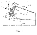
- FIG. 1 Illustrated schematically in Figure 1 is an exemplary annular combustor 10 of a gas turbine engine having an axial centerline axis 12.
- the combustor 10 may take any conventional form including a pair of radially outer and inner annular combustion liners 10a,b joined together at an upstream annular dome 10c, with the liners 10a,b being spaced radially apart to define an annular combustion chamber or zone 10d.
- a conventional compressor Disposed upstream of the combustor 10 is a conventional compressor (not shown) which provides pressurized air 14 to the combustor 10 wherein it is mixed with fuel 16 to form a fuel and air mixture 18a which is suitably ignited for generating hot combustion gases 18b in the combustion zone 10d.
- the combustion gases 18b are discharged from the combustor 10 and flow to one or more turbine stages (not shown) which extract energy therefrom for powering the engine and producing useful workout for either powering an aircraft in flight, or for marine or industrial applications.
- the combustor 10 includes a plurality of circumferentially spaced apart carburetors 20 which mix the compressed air 14 and fuel 16 to provide a larger plurality of injection points for the resulting fuel and air mixtures 18a therefrom for reducing NO x emissions.
- the fuel 16 is typically in liquid form, atomized by air in the carburetor, and produces in the combustion zone 10d a diffusion flame during operation. It is conventionally known that NO x emissions can be reduced by reducing exposure time within the near stoichiometric flame temperature region. This is typically accomplished by obtaining lean mixtures of low fuel drop size and low characteristic flame lengths in correspondingly short combustors.
- flame length is proportional to recirculation zone length within the combustor which in turn is proportional to swirler diameter. Since swirler diameter is proportional to the square root of swirler flow, a halving of NO x emissions may be accomplished by a four-fold increase in the number of injection points within the combustor, with all else being equal. Further reduction in NO x emissions may be obtained by narrow focus swirlers with collapsed sprays, low drop size, and well distributed lean mixtures.
- each of the carburetors 20 includes a respective, single fuel injector 22 which feeds the fuel 1 6 to a plurality of fuel-atomizing air swirlers 24 circumferentially spaced around the common fuel injector 22.
- four swirlers 24 cooperate with the common fuel injector 20, although two, three, or more swirlers 24 could otherwise be associated with a common fuel injector 22.
- identical carburetors 20 like that illustrated in Figure 2 are circumferentially spaced apart from each other around the circumference of the combustor dome 10c, with the individual swirlers 24 being circumferentially spaced apart around each of the corresponding fuel injectors 22.
- each fuel injector 22 provides a corresponding plurality of circumferential fuel-and-air injection points spaced circumferentially along the combustor dome 10c for reducing NO x emissions.
- Typical carburetors include a single fuel injector cooperating with a single air swirler for providing a single injection point which would experience the problems disclosed above if the increased number of injection points were obtained by simply increasing the number of fuel injectors and cooperating swirlers.
- NO x reduction may be achieved without undesirably increasing the number of fuel injectors themselves, thusly avoiding the above mentioned problems.
- each fuel injector 22 includes a central, hollow stem 22a through which the fuel 16 is provided from a conventional fuel supply (not shown).
- the fuel stem 22a is conventionally thermally insulated by using a tubular heat shield 22b spaced radially outwardly therefrom to provide an air-insulating gap therebetween.
- the distal, tip end of the fuel stem 22a is closed, and includes a plurality of hollow pipes or spokes 22c extending radially outwardly from the stem 22a and in flow communication therewith.
- Each of the spokes 22c includes a fuel outlet 22d disposed at respective distal or outer ends thereof, which is shown in more detail in Figure 4.
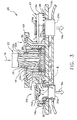
- Each of the swirlers 24 includes a tubular body 24a as illustrated in Figure 3 which may be formed by conventional casting along with its integral components described below in a manner similar to conventional air swirlers, but modified for use in the present invention.
- Each tubular body 24a includes a cylindrical fuel inlet 24b extending radially therethrough in flow communication with a respective one of the fuel outlets 22d for receiving the fuel 16 therefrom.
- each of the swirler fuel inlets 24b preferably extends generally tangentially through the body 24a to swirl or spiral the fuel inside the body 24a in a first rotational direction shown clockwise in Figure 2.
- each of the swirlers 24 includes a plurality of circumferentially spaced apart, stationary first swirl vanes 24c to swirl a portion of the compressed air 14 for mixing with the fuel 16 from the fuel inlet 24b to form and then discharge from the swirler 24 a fuel and air mixture 18a.
- the swirl vanes 24c are arranged in a first row to define a first air inlet of each of the swirlers 24, and are disposed coaxially with the swirler body 24a for swirling a respective portion of the air 14 inside the center channel of the body.
- the first swirl vanes 24c are inclined tangentially to swirl the air 14 therethrough in a second, or counterclockwise rotational direction, opposite to the first direction for the fuel 16.
- a plurality of circumferentially spaced apart second swirl vanes 24d are disposed coaxially with the body 24a in another row defining a second air inlet of each swirler 24.
- the second swirl vanes 24d are spaced axially forwardly or upstream from the first swirl vanes 24c for swirling another portion of the air 14 into the body 24a.
- the second swirl vanes 24d are preferably inclined tangentially oppositely to the first swirl vanes 24c to swirl the air 14 therethrough in the first rotational direction for obtaining counter-swirl.
- the swirler fuel inlet 24b is preferably disposed axially between the rows of first and second swirl vanes 24c,d for injecting the fuel therebetween for mixing therewith and ejection from a common outlet 24e of the swirler body 24a as the fuel and air mixture 18a.
- the fuel stem 22a has a suitable inner diameter for providing a sufficient total flowrate of the fuel 16 which is divided between the several fuel spokes 22c.
- the fuel is suitably metered by the size of the fuel outlets 22d in a simple orifice configuration. If desired, a conventional spin disk or series orifice arrangement may instead be used in designs having relatively low flow numbers for metering the fuel.
- the air 14 provided in each swirler 24 is metered by the respective air inlets defined by the first and second swirl vanes 24c,d. In this way, a suitably lean fuel and air mixture 18a may be obtained from each of the swirlers 24 for increasing the number of mixture injection points associated with a common fuel injector 22.
- swirlers are conventionally known including counter-rotational swirlers of the general type illustrated in Figure 3.
- a conventional swirler typically mounts its fuel injector coaxially therein at a forward end thereof.
- the swirlers 24 illustrated in Figure 3 are suitably modified to block the forward end thereof, and providing a circumferential air inlet using the second swirl vanes 24d.
- the swirler fuel inlet 24b is provided to the side of the swirler body 24a axially between the first and second swirl vanes 24c,d.
- the swirlers 24 may be otherwise conventional in configuration, and conventionally manufactured in a common casting for example.
- each of the swirlers 24 is suitably fixedly joined to the combustor dome 10c by brazing or welding, for example.
- the combustor includes a plurality of integral tubular pockets 10e formed on the forward side of the combustor dome 10c in which each of the respective swirlers 24 may be mounted.
- Each pocket 10e includes a plurality of circumferentially spaced apart air holes 26 aligned with the first swirl vanes 24c for admitting the air 14 thereto.
- a tubular retainer 10f extending integrally outwardly from the forward side of the combustor dome 10c centered within the pockets 10e for mounting the fuel injector 22 in a floating arrangement to the combustor dome 10c.
- a tubular ferrule 28 is disposed between the retainer 10f and the fuel injector 22 for mounting the fuel injector 22 to the combustor dome 10c in a conventional floating arrangement.
- the fuel injector 22 is allowed to slide axially inside the ferrule 28, and the ferrule 28 includes a radial flange at one end which is circumferentially trapped in a corresponding groove at the forward end of the retainer 10f for allowing differential radial movement therebetween.
- the combustor dome may be designed specifically for the improved carburetors 20, without requiring design changes in the combustor casing through which the fuel stems are mounted.
- the fuel injector 22 preferably further includes an integral sleeve 22e formed at its distal end for surrounding the fuel spokes 22c.
- the sleeve 22e includes a plurality of circumferentially spaced apart access ports 30, shown in more particularity in Figure 4, which extend radially through the sleeve for receiving respective ones of the fuel spokes 22c and outlets 22d thereof.
- the sleeve 22e is spaced radially outwardly from the heat shield 22b surrounding the fuel stem 22a to define an annular sleeve inlet 32 at the distal or outer end of the sleeve, with the proximal or inner end of the sleeve being integrally joined with the tip of the stem 22a.
- the sleeve inlet 32 receives and channels another portion of the compressed air 14 through the sleeve ports 30 and around the individual fuel outlets 22d.
- the sleeve ports 30 are suitably sized for metering the air 14 therethrough which initially mixes with the fuel 16 being discharged from the fuel outlet 22d.
- the ferrule 28 includes a plurality of circumferentially spaced apart access ports 34 extending radially therethrough in alignment with respective ones of the fuel outlets 22d at one end, and the fuel inlets 24b of the swirlers 24 at an opposite end for channeling fuel therebetween.
- the ferrule ports 34 are suitably large and have a bellmouth shape for receiving both the fuel 16 from the fuel outlets 22d, and the surrounding air 14 from the sleeve ports 30.
- a plurality of air holes 36 are disposed around the circumference of the floating flange of the ferrule 28 for providing flow communication between the ferrule 28 and the concentric retainer 10f for allowing purge flow therebetween.
- fuel 16 is channeled through the insulated fuel stem 22a to each of the fuel spokes 22c which distribute the fuel to the respective swirlers 24.
- the fuel is ejected from the fuel outlets 22d at the end of each spoke and is metered thereby and is directed radially through the aligned holes in the sleeve 22e, ferrule 28, retainer 10f, and into the respective fuel inlets 24b in each of the swirlers 24.
- Air enters each of the swirlers 24 through the two rows of swirl vanes 24c,d for mixing with and further atomizing the fuel 16 injected therein through the fuel inlets 24b.
- the swirlers 24, including their vanes 24c,d, may be conventionally configured for co-rotation or counter-rotation airflow for mixing with the injected fuel to provide relatively low drop size fuel and lean fuel/air mixtures 18a discharged therefrom.
- the swirlers 24 may be configured for narrowly focusing the fuel and air mixtures 18a with collapsed sprays and well distributed lean mixtures for further reducing NO x emissions.
- Reduced NO x emissions may therefore be obtained without an increase in the number of fuel injector stems 22a, which avoids an increase in complexity, cost, and weight if more fuel stems were otherwise used. Fewer fuel stems 22a requires fewer perforations through the combustor casing and reduces the likelihood of undesirable fuel coking.
- the carburetors 22 provide relatively simple airblast atomization having plain jet injection of the fuel 16 between the injector fuel outlets 22d and the swirler fuel inlet 24b.
- the swirlers 24 include conventional pre-filming tubular surfaces therein for enhanced atomization.
- the increased number of injection points provided by the multiple swirlers 24 with the common fuel injectors 22 provides an improved mechanism for correspondingly reducing NO x emissions and, a lower pattern factor may be achieved with the increased number of injection points.
- the profile factor may be varied or trimmed in the radial direction by incorporating different sizing in the swirlers and injector fuel outlets 22d for adjusting the corresponding fuel and air mixtures 18a from each of the swirlers.
- suitable fuel staging may be incorporated into the fuel stems 22a for separately controlling the fuel delivery to each of the radial spokes 22c.
- the individual swirlers 24 are fixedly joined to the combustor dome 10c, with the fuel injector 22 being mounted in a floating arrangement thereto.
- the several swirlers 24 associated with each fuel injector 22 may be joined together and collectively joined to the combustor dome 10c in a suitable floating arrangement relative thereto instead of being fixed thereto. In this way, the floating ferrule 28 may be eliminated, and the fuel injector 22 instead mounted directly to the floating swirler assembly associated therewith.
Landscapes
- Engineering & Computer Science (AREA)
- Chemical & Material Sciences (AREA)
- Combustion & Propulsion (AREA)
- Mechanical Engineering (AREA)
- General Engineering & Computer Science (AREA)
Claims (10)
- Vergaser (20) enthaltend:einen Brennstoffinjektor (22), der an einem geschlossenen entfernten Ende endet und mehrere auf dem Umfang im Abstand angeordnete Brennstoff-Auslässe (22d) hat, die an dem entfernten Ende radial verlaufen, undmehrere Luftverwirbler (24), die auf dem Umfang im Abstand um den Brennstoffinjektor herum angeordnet sind und die jeweils einen radialen Brennstoff-Einlass (24b), der mit einem entsprechenden der Brennstoff-Auslässe (22d) in Strömungsverbindung angeordnet sind, um von diesen Brennstoff radial zu empfangen, und jeweils mehrere Verwirblerschaufeln (24c,d) haben, um Luft zu verwirbeln zum Mischen mit dem Brennstoff aus dem Brennstoff-Einlass (24b) innerhalb jedes Verwirblers (24).
- Vergaser nach Anspruch 1, wobei der Brennstoffinjektor ferner einen hohlen Steg (22a) zum Leiten des Brennstoffes und mehrere hohle Speichen (22c) aufweist, die von dem Steg (22a) radial nach aussen verlaufen und mit diesem in Strömungsverbindung sind, und die Brennstoff-Auslässe (22d) an entsprechenden äusseren Enden der Speichen (22c) angeordnet sind.
- Vergaser nach Anspruch 2, wobei jeder Verwirbler (24) ferner enthält:wobei der Brennstoff-Einlass (24b) axial zwischen den Reihen der ersten und zweiten Verwirbelungsschaufeln (24c,d) angeordnet ist, zum Einspritzen des Brennstoffes dazwischen zum Mischen damit und Ausstossen aus einem gemeinsamen Auslass (24e) des Körper (24a) als ein Brennstoff- und Luftgemisch.einen rohrförmigen Körper (24a) mit dem Brennstoff-Einlass (24b), der radial davon ausgeht,eine Reihe erster Verwirbelungsschaufeln (24c), die koaxial zu dem Körper (24a) angeordnet sind, zum Verwirbeln eines Teils der Luft in den Körper (24a),eine Reihe zweiter Verwirbelungsschaufeln (24d), die koaxial zu dem Körper (24a) und im Abstand von den ersten Verwirbelungsschaufeln (24c) angeordnet sind, zum Verwirbeln eines anderen Teils der Luft in den Körper (24a), und
- Vergaser nach Anspruch 3, wobei der Brennstoffinjektor ferner eine integrale Buchse (22e) aufweist, die die Brennstoff-Speichen (22c) umgibt und mehrere Zugangsöffnungen (30) hat, die radial durch diese hindurchführen zur Aufnahme entsprechender Brennstoff-Auslässe (22d), wobei die Buchse (22e) im Abstand von dem Brennstoffinjektor (22) angeordnet ist, um einen ringförmigen Einlass zu bilden zum Aufnehmen und Leiten eines anderen Teils (14) der Luft durch die Buchsenöffnungen (30) und um die Brenntsoff-Auslässe herum.
- Vergaser nach Anspruch 4, wobei ferner ein rohrförmiger Endring (28) vorgesehen ist, der die Injektor-Buchse (22e) umgibt, zum Befestigen des Brennstoff-Injektors (22) an einem Brenner-Dom (10c), wobei der Endring (28) mehrere auf dem Umfang im Abstand angeordnete Zugangsöffnungen (34) aufweist, die radial hindurchführen in Ausrichtung mit entsprechenden Brennstoff-Auslässen (22d) zum Leiten von Brennstoff dazwischen.
- Vergaser nach Anspruch 5, wobei die Brennstoff-Einlässe (24b) des Verwirblers tangential durch den Körper (24a) verlaufen, um dem Brennstoff darin eine spiralförmige Bewegung in einer ersten Drehrichtung zu erteilen.
- Vergaser nach Anspruch 6, wobei die ersten Verwirbelungsschaufeln (24c) schräg verlaufen, um die hindurchtretende Luft in einer zweiten Drehrichtung, entgegengesetzt zur ersten Drehrichtung, zu verwirbeln, und wobei die zweiten Verwirbelungsschaufeln (24d) schräg verlaufen, um die hindurchtretende Luft in der ersten Drehrichtung zu verwirbeln.
- Vergaser nach Anspruch 5 in Kombination mit einem Brennerdom (10c), wobei die Verwirbler (24) fest mit diesem verbunden sind und der Endring (28) verschiebbar damit verbunden ist, damit der Brennstoffinjektor (22) relativ zu dem Brennerdom (10c) schwimmen kann.
- Vergaser nach Anspruch 8, wobei die Verwirbler (24) in dem Brennerdom (10c) auf dem Umfang im Abstand angeordnet sind zum Bilden mehrerer Umfangs-Einspritzpunkte von dem gemeinsamen Brennstoffinjektor (22).
- Vergaser nach Anspruch 8, wobei ferner ein ringförmiger Halter (10f) vorgesehen ist, der mit dem Brennerdom (10c) verbunden ist und den Endring (28) darin aufnimmt.
Applications Claiming Priority (2)
| Application Number | Priority Date | Filing Date | Title |
|---|---|---|---|
| US899116 | 1997-07-23 | ||
| US08/899,116 US5930999A (en) | 1997-07-23 | 1997-07-23 | Fuel injector and multi-swirler carburetor assembly |
Publications (3)
| Publication Number | Publication Date |
|---|---|
| EP0893650A2 EP0893650A2 (de) | 1999-01-27 |
| EP0893650A3 EP0893650A3 (de) | 1999-05-12 |
| EP0893650B1 true EP0893650B1 (de) | 2004-05-12 |
Family
ID=25410502
Family Applications (1)
| Application Number | Title | Priority Date | Filing Date |
|---|---|---|---|
| EP98305865A Expired - Lifetime EP0893650B1 (de) | 1997-07-23 | 1998-07-23 | Vergaser mit multiplen Verwirbelungsvorrichtungen |
Country Status (3)
| Country | Link |
|---|---|
| US (1) | US5930999A (de) |
| EP (1) | EP0893650B1 (de) |
| DE (1) | DE69823749T2 (de) |
Families Citing this family (38)
| Publication number | Priority date | Publication date | Assignee | Title |
|---|---|---|---|---|
| US6339923B1 (en) | 1998-10-09 | 2002-01-22 | General Electric Company | Fuel air mixer for a radial dome in a gas turbine engine combustor |
| JP4683787B2 (ja) * | 2001-03-09 | 2011-05-18 | 大阪瓦斯株式会社 | バーナ装置及びガスタービンエンジン |
| US6442940B1 (en) * | 2001-04-27 | 2002-09-03 | General Electric Company | Gas-turbine air-swirler attached to dome and combustor in single brazing operation |
| US6898926B2 (en) * | 2003-01-31 | 2005-05-31 | General Electric Company | Cooled purging fuel injectors |
| US6959535B2 (en) | 2003-01-31 | 2005-11-01 | General Electric Company | Differential pressure induced purging fuel injectors |
| US6898938B2 (en) | 2003-04-24 | 2005-05-31 | General Electric Company | Differential pressure induced purging fuel injector with asymmetric cyclone |
| US9200607B2 (en) | 2007-12-04 | 2015-12-01 | Steven Wilson | Apparatus for spray injection of liquid or gas |
| US8555866B2 (en) | 2007-12-04 | 2013-10-15 | Steven Wilson | Apparatus for spray injection of liquid or gas |
| US8147121B2 (en) * | 2008-07-09 | 2012-04-03 | General Electric Company | Pre-mixing apparatus for a turbine engine |
| US8112999B2 (en) * | 2008-08-05 | 2012-02-14 | General Electric Company | Turbomachine injection nozzle including a coolant delivery system |
| US8800895B2 (en) * | 2008-08-27 | 2014-08-12 | Woodward, Inc. | Piloted variable area fuel injector |
| US9500368B2 (en) * | 2008-09-23 | 2016-11-22 | Siemens Energy, Inc. | Alternately swirling mains in lean premixed gas turbine combustors |
| US8297059B2 (en) * | 2009-01-22 | 2012-10-30 | General Electric Company | Nozzle for a turbomachine |
| US9140454B2 (en) * | 2009-01-23 | 2015-09-22 | General Electric Company | Bundled multi-tube nozzle for a turbomachine |
| US8539773B2 (en) * | 2009-02-04 | 2013-09-24 | General Electric Company | Premixed direct injection nozzle for highly reactive fuels |
| US20110073071A1 (en) * | 2009-09-30 | 2011-03-31 | Woodward Governor Company | Internally Nested Variable-Area Fuel Nozzle |
| US9683739B2 (en) * | 2009-11-09 | 2017-06-20 | Woodward, Inc. | Variable-area fuel injector with improved circumferential spray uniformity |
| RU2442932C1 (ru) * | 2010-06-01 | 2012-02-20 | Общество с ограниченной ответственностью "Новые технологии" | Малоэмиссионная горелка |
| US20120210717A1 (en) * | 2011-02-21 | 2012-08-23 | General Electric Company | Apparatus for injecting fluid into a combustion chamber of a combustor |
| US8893500B2 (en) | 2011-05-18 | 2014-11-25 | Solar Turbines Inc. | Lean direct fuel injector |
| US8919132B2 (en) | 2011-05-18 | 2014-12-30 | Solar Turbines Inc. | Method of operating a gas turbine engine |
| RU2511980C2 (ru) * | 2011-10-04 | 2014-04-10 | Федеральное государственное бюджетное образовательное учреждение высшего профессионального образования "Воронежский государственный технический университет" | Способ сжигания топлива |
| US9182124B2 (en) | 2011-12-15 | 2015-11-10 | Solar Turbines Incorporated | Gas turbine and fuel injector for the same |
| AU2012375461B2 (en) * | 2012-03-29 | 2015-10-29 | Exxonmobil Upstream Research Company | Turbomachine combustor assembly |
| US9267690B2 (en) | 2012-05-29 | 2016-02-23 | General Electric Company | Turbomachine combustor nozzle including a monolithic nozzle component and method of forming the same |
| US8904798B2 (en) | 2012-07-31 | 2014-12-09 | General Electric Company | Combustor |
| US9115671B2 (en) | 2012-11-07 | 2015-08-25 | Benebe, Inc. | Hybrid carburetor and fuel injection assembly for an internal combustion engine |
| US9677766B2 (en) * | 2012-11-28 | 2017-06-13 | General Electric Company | Fuel nozzle for use in a turbine engine and method of assembly |
| US9353950B2 (en) | 2012-12-10 | 2016-05-31 | General Electric Company | System for reducing combustion dynamics and NOx in a combustor |
| US10260748B2 (en) | 2012-12-21 | 2019-04-16 | United Technologies Corporation | Gas turbine engine combustor with tailored temperature profile |
| WO2014204449A1 (en) | 2013-06-18 | 2014-12-24 | Woodward, Inc. | Gas turbine engine flow regulating |
| US9482433B2 (en) * | 2013-11-11 | 2016-11-01 | Woodward, Inc. | Multi-swirler fuel/air mixer with centralized fuel injection |
| RU2567899C2 (ru) * | 2014-02-19 | 2015-11-10 | Андрей Аркадьевич Мельников | Устройство для сжигания топлива |
| US10267524B2 (en) * | 2015-09-16 | 2019-04-23 | Woodward, Inc. | Prefilming fuel/air mixer |
| JP6638935B2 (ja) * | 2015-12-22 | 2020-02-05 | 川崎重工業株式会社 | 燃料噴射装置 |
| US10724740B2 (en) | 2016-11-04 | 2020-07-28 | General Electric Company | Fuel nozzle assembly with impingement purge |
| US10634353B2 (en) * | 2017-01-12 | 2020-04-28 | General Electric Company | Fuel nozzle assembly with micro channel cooling |
| RU2696519C1 (ru) * | 2018-05-08 | 2019-08-02 | АО "Казанское моторостроительное производственное объединение" (АО "КМПО") | Кольцевая камера сгорания газотурбинного двигателя |
Family Cites Families (15)
| Publication number | Priority date | Publication date | Assignee | Title |
|---|---|---|---|---|
| US30160A (en) * | 1860-09-25 | Lock for buiiglar-proof pockets | ||
| US2583416A (en) * | 1948-12-07 | 1952-01-22 | Lucas Ltd Joseph | Liquid fuel vaporizer |
| US2595765A (en) * | 1949-01-01 | 1952-05-06 | Lucas Ltd Joseph | Liquid fuel burner |
| US3236048A (en) * | 1963-09-25 | 1966-02-22 | Gen Motors Corp | Vaporizing manifold and flameholder for afterburners |
| GB1421399A (en) * | 1972-11-13 | 1976-01-14 | Snecma | Fuel injectors |
| US3834159A (en) * | 1973-08-03 | 1974-09-10 | Gen Electric | Combustion apparatus |
| DE2341904B2 (de) * | 1973-08-18 | 1978-07-27 | Motoren- Und Turbinen-Union Muenchen Gmbh, 8000 Muenchen | Brennkammer für Gasturbinentriebwerke |
| US4260367A (en) * | 1978-12-11 | 1981-04-07 | United Technologies Corporation | Fuel nozzle for burner construction |
| CA1306873C (en) * | 1987-04-27 | 1992-09-01 | Jack R. Taylor | Low coke fuel injector for a gas turbine engine |
| US5261226A (en) * | 1991-08-23 | 1993-11-16 | Westinghouse Electric Corp. | Topping combustor for an indirect fired gas turbine |
| US5237820A (en) * | 1992-01-02 | 1993-08-24 | General Electric Company | Integral combustor cowl plate/ferrule retainer |
| US5437158A (en) * | 1993-06-24 | 1995-08-01 | General Electric Company | Low-emission combustor having perforated plate for lean direct injection |
| FR2730555B1 (fr) * | 1995-02-15 | 1997-03-14 | Snecma | Ensemble d'injection de carburant pour chambre de combustion de turbines a gaz |
| US5680766A (en) * | 1996-01-02 | 1997-10-28 | General Electric Company | Dual fuel mixer for gas turbine combustor |
| US5675971A (en) * | 1996-01-02 | 1997-10-14 | General Electric Company | Dual fuel mixer for gas turbine combustor |
-
1997
- 1997-07-23 US US08/899,116 patent/US5930999A/en not_active Expired - Fee Related
-
1998
- 1998-07-23 DE DE69823749T patent/DE69823749T2/de not_active Expired - Lifetime
- 1998-07-23 EP EP98305865A patent/EP0893650B1/de not_active Expired - Lifetime
Also Published As
| Publication number | Publication date |
|---|---|
| DE69823749T2 (de) | 2005-05-12 |
| DE69823749D1 (de) | 2004-06-17 |
| US5930999A (en) | 1999-08-03 |
| EP0893650A2 (de) | 1999-01-27 |
| EP0893650A3 (de) | 1999-05-12 |
Similar Documents
| Publication | Publication Date | Title |
|---|---|---|
| EP0893650B1 (de) | Vergaser mit multiplen Verwirbelungsvorrichtungen | |
| US8171735B2 (en) | Mixer assembly for gas turbine engine combustor | |
| US5899075A (en) | Turbine engine combustor with fuel-air mixer | |
| EP0700499B1 (de) | Verbrennungskammer eines gasturbinenmotors | |
| US6272840B1 (en) | Piloted airblast lean direct fuel injector | |
| US5123248A (en) | Low emissions combustor | |
| US4763481A (en) | Combustor for gas turbine engine | |
| EP0769657B1 (de) | Vormischbrenner für eine Gasturbinenbrennkammer mit niedriger Schadstoffemission | |
| US6381964B1 (en) | Multiple annular combustion chamber swirler having atomizing pilot | |
| US5444982A (en) | Cyclonic prechamber with a centerbody | |
| US5199265A (en) | Two stage (premixed/diffusion) gas only secondary fuel nozzle | |
| EP1262718B1 (de) | Methode und Anlage zur Reduzierung der Schadstoffausstosses der Brennkammer | |
| US6374615B1 (en) | Low cost, low emissions natural gas combustor | |
| US8387393B2 (en) | Flashback resistant fuel injection system | |
| US20100263382A1 (en) | Dual orifice pilot fuel injector | |
| US20120151930A1 (en) | Fuel atomization dual orifice fuel nozzle | |
| US5142858A (en) | Compact flameholder type combustor which is staged to reduce emissions | |
| EP0924469A2 (de) | Drallerzeuger ohne Venturi | |
| US20070028595A1 (en) | High pressure gas turbine engine having reduced emissions | |
| EP1193447B1 (de) | Brennkammer mit mehreren Einspritzdüsen | |
| JP2002139221A (ja) | エンジン排気エミッション減少のための燃料ノズル組立体 | |
| US6571559B1 (en) | Anti-carboning fuel-air mixer for a gas turbine engine combustor | |
| JP2008128631A (ja) | 空気と燃料の混合物を噴射する装置と、このような装置を備える燃焼チャンバ及びターボ機械 | |
| EP0773410B1 (de) | Kraftstoff-Luft Mischrohr | |
| GB2176274A (en) | Combustor for gas turbine engine |
Legal Events
| Date | Code | Title | Description |
|---|---|---|---|
| PUAI | Public reference made under article 153(3) epc to a published international application that has entered the european phase |
Free format text: ORIGINAL CODE: 0009012 |
|
| AK | Designated contracting states |
Kind code of ref document: A2 Designated state(s): DE FR GB IT |
|
| AX | Request for extension of the european patent |
Free format text: AL;LT;LV;MK;RO;SI |
|
| PUAL | Search report despatched |
Free format text: ORIGINAL CODE: 0009013 |
|
| AK | Designated contracting states |
Kind code of ref document: A3 Designated state(s): AT BE CH CY DE DK ES FI FR GB GR IE IT LI LU MC NL PT SE |
|
| AX | Request for extension of the european patent |
Free format text: AL;LT;LV;MK;RO;SI |
|
| RHK1 | Main classification (correction) |
Ipc: F23D 23/00 |
|
| 17P | Request for examination filed |
Effective date: 19991112 |
|
| AKX | Designation fees paid |
Free format text: DE FR GB IT |
|
| 17Q | First examination report despatched |
Effective date: 20011011 |
|
| GRAP | Despatch of communication of intention to grant a patent |
Free format text: ORIGINAL CODE: EPIDOSNIGR1 |
|
| GRAS | Grant fee paid |
Free format text: ORIGINAL CODE: EPIDOSNIGR3 |
|
| GRAA | (expected) grant |
Free format text: ORIGINAL CODE: 0009210 |
|
| AK | Designated contracting states |
Kind code of ref document: B1 Designated state(s): DE FR GB IT |
|
| REG | Reference to a national code |
Ref country code: GB Ref legal event code: FG4D |
|
| REF | Corresponds to: |
Ref document number: 69823749 Country of ref document: DE Date of ref document: 20040617 Kind code of ref document: P |
|
| ET | Fr: translation filed | ||
| PLBE | No opposition filed within time limit |
Free format text: ORIGINAL CODE: 0009261 |
|
| STAA | Information on the status of an ep patent application or granted ep patent |
Free format text: STATUS: NO OPPOSITION FILED WITHIN TIME LIMIT |
|
| 26N | No opposition filed |
Effective date: 20050215 |
|
| PGFP | Annual fee paid to national office [announced via postgrant information from national office to epo] |
Ref country code: IT Payment date: 20100728 Year of fee payment: 13 Ref country code: FR Payment date: 20100805 Year of fee payment: 13 Ref country code: DE Payment date: 20100728 Year of fee payment: 13 |
|
| PGFP | Annual fee paid to national office [announced via postgrant information from national office to epo] |
Ref country code: GB Payment date: 20100726 Year of fee payment: 13 |
|
| GBPC | Gb: european patent ceased through non-payment of renewal fee |
Effective date: 20110723 |
|
| REG | Reference to a national code |
Ref country code: FR Ref legal event code: ST Effective date: 20120330 |
|
| PG25 | Lapsed in a contracting state [announced via postgrant information from national office to epo] |
Ref country code: DE Free format text: LAPSE BECAUSE OF NON-PAYMENT OF DUE FEES Effective date: 20120201 Ref country code: FR Free format text: LAPSE BECAUSE OF NON-PAYMENT OF DUE FEES Effective date: 20110801 |
|
| REG | Reference to a national code |
Ref country code: DE Ref legal event code: R119 Ref document number: 69823749 Country of ref document: DE Effective date: 20120201 |
|
| PG25 | Lapsed in a contracting state [announced via postgrant information from national office to epo] |
Ref country code: IT Free format text: LAPSE BECAUSE OF NON-PAYMENT OF DUE FEES Effective date: 20110723 |
|
| PG25 | Lapsed in a contracting state [announced via postgrant information from national office to epo] |
Ref country code: GB Free format text: LAPSE BECAUSE OF NON-PAYMENT OF DUE FEES Effective date: 20110723 |