EP0893610A1 - Spreizdübel - Google Patents
Spreizdübel Download PDFInfo
- Publication number
- EP0893610A1 EP0893610A1 EP98110296A EP98110296A EP0893610A1 EP 0893610 A1 EP0893610 A1 EP 0893610A1 EP 98110296 A EP98110296 A EP 98110296A EP 98110296 A EP98110296 A EP 98110296A EP 0893610 A1 EP0893610 A1 EP 0893610A1
- Authority
- EP
- European Patent Office
- Prior art keywords
- expansion
- dowel
- shaft
- dowel shaft
- borehole
- Prior art date
- Legal status (The legal status is an assumption and is not a legal conclusion. Google has not performed a legal analysis and makes no representation as to the accuracy of the status listed.)
- Granted
Links
- 230000007704 transition Effects 0.000 claims description 11
- 238000004873 anchoring Methods 0.000 claims description 5
- 238000005336 cracking Methods 0.000 description 3
- 230000000694 effects Effects 0.000 description 1
Images
Classifications
-
- F—MECHANICAL ENGINEERING; LIGHTING; HEATING; WEAPONS; BLASTING
- F16—ENGINEERING ELEMENTS AND UNITS; GENERAL MEASURES FOR PRODUCING AND MAINTAINING EFFECTIVE FUNCTIONING OF MACHINES OR INSTALLATIONS; THERMAL INSULATION IN GENERAL
- F16B—DEVICES FOR FASTENING OR SECURING CONSTRUCTIONAL ELEMENTS OR MACHINE PARTS TOGETHER, e.g. NAILS, BOLTS, CIRCLIPS, CLAMPS, CLIPS OR WEDGES; JOINTS OR JOINTING
- F16B13/00—Dowels or other devices fastened in walls or the like by inserting them in holes made therein for that purpose
- F16B13/04—Dowels or other devices fastened in walls or the like by inserting them in holes made therein for that purpose with parts gripping in the hole or behind the reverse side of the wall after inserting from the front
- F16B13/06—Dowels or other devices fastened in walls or the like by inserting them in holes made therein for that purpose with parts gripping in the hole or behind the reverse side of the wall after inserting from the front combined with expanding sleeve
- F16B13/063—Dowels or other devices fastened in walls or the like by inserting them in holes made therein for that purpose with parts gripping in the hole or behind the reverse side of the wall after inserting from the front combined with expanding sleeve by the use of an expander
- F16B13/065—Dowels or other devices fastened in walls or the like by inserting them in holes made therein for that purpose with parts gripping in the hole or behind the reverse side of the wall after inserting from the front combined with expanding sleeve by the use of an expander fastened by extracting the screw, nail or the like
Definitions
- the invention relates to an expansion anchor for anchoring in a borehole in one Masonry with the features of the preamble of claim 1.
- expansion anchor is known from DE-G 87 11 684.
- the well-known expansion anchor has a cylindrical dowel shaft with a conical expansion body on its front end, with a tapered end of the expansion body facing the dowel shaft is.
- an expansion sleeve is the dowel shaft or placed around the expansion body by pulling in the expansion body is expandable into the expansion sleeve and thereby the expansion plug in the borehole anchored.
- the End of the dowel shaft facing away from the expansion body is threaded by means of of which the expansion body is retractable into the expansion sleeve via the dowel shaft.
- the expansion sleeve which has not yet spread out, lies against a borehole wall, it sticks in the borehole and is held up by the masonry when the expansion body is pulled in.
- the dowel shaft When the expansion body is pulled into the expansion sleeve, the dowel shaft becomes attached to it Torque applied to the thread. This torque is at best partially dismantled over the length of the dowel shaft, provided this is an oversize has opposite the borehole, so that friction between dowel shaft and masonry consists. In addition, a counter moment acts on the expansion body, which during and after pulling the expansion body into the expansion sleeve from the expansion sleeve in the borehole is held against twisting. If the dowel shaft is undersized in the borehole the torque for retracting the expansion body into the expansion sleeve acts constantly over the entire length of the dowel shaft to the expansion body.
- That torque causes a torsional stress, which is a tensile load for retracting the Spreading body is superimposed in the expansion sleeve.
- a torsional stress which is a tensile load for retracting the Spreading body is superimposed in the expansion sleeve.
- Particularly high material tensions cause the tensile load and the torsional stress at the transition from the dowel shaft to the expansion body.
- These material tensions can lead to cracking and lead to tearing of the expansion body from the dowel shaft, they limit that in any case Tightening torque of the expansion anchor and the pulling force of the expansion body into the Expansion sleeve and thus the force with which the expansion anchor is anchored in the masonry.
- the invention has for its object to provide an expansion anchor of the type mentioned Kind in such a way that a torsional stress is reduced.
- the Expansion dowel according to the invention has an anti-rotation device that the Secures dowel shaft against twisting in the borehole.
- the anti-rotation device can, for example, be non-positive or positive.
- Any non-circular cross-section that is in contact with the borehole wall can be considered and thereby when pulling the expansion body into the expansion sleeve on the thread torque applied to the dowel shaft preferably completely, at least however partially transferred to the masonry. This will put it on the dowel shaft acting torsional moment in the area of the anti-rotation device completely or at least partially dismantled, at the transition from the dowel shaft to the expansion body there is no or only a reduced torsional moment.
- the anti-rotation device is also conceivable as an eccentric dowel shaft section, for example to be provided as a kind of bend or double bend.
- the anti-rotation device is designed so that it has a drive-in resistance when inserting the expansion anchor enlarged in the borehole only to a limited extent.
- the expansion plug according to the invention has the advantage that when the expansion body is pulled in material stresses occurring in the expansion sleeve are reduced, so that a Pull-in thread applied pull-in torque and a pull-in force of the expansion body can be enlarged into the expansion sleeve. The risk of cracking and one Tearing of the expansion body from the dowel shaft is reduced.
- the anti-rotation device is preferably designed as a type of cam or as a polygon with an edge running approximately in the longitudinal direction of the dowel shaft is located radially outside a circumference of the dowel shaft, or as a laterally protruding one Rib or as toothing, which also runs approximately in the longitudinal direction, educated.
- These anti-rotation devices dig when the Expansion dowels in the drill hole in the masonry, they form one or more in Longitudinal furrows. You have the advantage of a high anti-rotation device effect, so are able to get a large torque from the dowel shaft transfer to the masonry, and cause only a low driving resistance.
- the anti-rotation device can basically on any Location of the dowel shaft.
- its anchor shaft has an undersize in relation to a nominal diameter of the borehole, which is used for anchoring the expansion anchor is attached to the masonry.
- the undersize the dowel shaft in relation to the borehole has the advantage of even pulling in and Anchoring forces.
- the term undersize is not to be seen strictly, the dowel shaft can with narrow drill holes at the lower tolerance range with less There is friction on the masonry, which is actually a transition fit is.
- the dowel shaft tapers at the transition to Spreader.
- the transition is to avoid voltage peaks in this area not designed as a ring step with all-round, almost rectangular edges, but the transition is designed, for example, as a cone or has a concave, circumferential one Rounding up.
- a chamfer on a fillet of a ring step also reduces voltage peaks, which can lead to cracking and tearing of the expansion body.
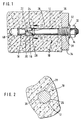
- the inventive, generally designated 10, shown in the drawing Expansion dowel has a cylindrical dowel shaft 12.
- a rear end of the dowel shaft 12 is provided with a thread 14, the outer diameter of which is somewhat is larger than a diameter of the dowel shaft 12.
- Pointing at its front end the dowel shaft 12 has a conical expansion body 16, the tapered end of which Dowel shaft 12 is facing.
- the dowel shaft 12 has a slightly smaller diameter than a diameter of the larger one End of the expansion body 16, which is approximately the same as the outer diameter of the thread 14 matches.
- a spreading sleeve 20 encompassing this is placed on the intermediate section 18, which has a continuous longitudinal slot 22.
- a transition 24 from the intermediate section 18 to dowel shaft 12 is rounded concavely.
- the dowel shaft 12 has a low radial collar 26, to which the transition 24 connects.
- the radial collar 26 is after two outwardly projecting, longitudinal ribs 28 on opposite one another Provide places ( Figure 2).
- the ribs 28 are larger radially over the end Diameter of the expansion body 16 and over the outer diameter of the thread 14 before.
- a nut 30 is on the Screwed-in thread 14, which is under a washer 32.
- the expansion plug 10 For fastening an object, for example a bracket 34, to a masonry 36, the expansion plug 10 according to the invention with the expansion body 16 is ahead through a hole 38 in the bracket 34 into a previously drilled hole in the masonry 36 40 introduced.
- the borehole 40 When inserting or driving into the borehole 40 penetrate the Ribs 28 in the masonry 36, they form an anti-rotation device of the Expansion dowel 10.
- the expansion sleeve 20 is when the expansion dowel 10 is inserted into the Borehole 40 is elastically compressed radially, i.e. it is stuck in hole 40. That Depending on its tolerance, borehole 40 has approximately one with the diameter of the larger end of the expansion body 16 and the outer diameter of the thread 14 matching diameters. The borehole 40 is therefore oversized with respect to the dowel shaft 12.
- the nut 30 is tightened and thereby the expansion body 16 is drawn into the expansion sleeve 20.
- the clamping force the expansion sleeve 20 in the borehole 40 prevents the expansion body 16 from Pulls expansion sleeve 20 out of borehole 40.
- the expansion sleeve 20 is from the expansion body 16 radially expanded and the expansion anchor 10 in this way in the masonry 36 anchored.
- the expansion plug 10 at the transition 24 is of diameter of the dowel shaft 12 to the smaller diameter of the intermediate section 18 or the tapered end of the expansion body 16 free from torsional stress, from the anti-rotation device 26, 28 up to and including the expansion body 16 act only tensile forces on the expansion anchor 10. To avoid voltage peaks the transition 24 is rounded concavely.
Landscapes
- Engineering & Computer Science (AREA)
- General Engineering & Computer Science (AREA)
- Mechanical Engineering (AREA)
- Dowels (AREA)
- Joining Of Building Structures In Genera (AREA)
- Piles And Underground Anchors (AREA)
- Valve-Gear Or Valve Arrangements (AREA)
- Inorganic Insulating Materials (AREA)
- Control Of Motors That Do Not Use Commutators (AREA)
- Tents Or Canopies (AREA)
- Furnace Housings, Linings, Walls, And Ceilings (AREA)
- Reinforcement Elements For Buildings (AREA)
- Thermistors And Varistors (AREA)
- Valve Device For Special Equipments (AREA)
- Gripping On Spindles (AREA)
Abstract
Description
- Figur 1
- einen erfindungsgemäßen in ein Bohrloch eingesetzten Spreizdübel vor dem Aufspreizen einer Spreizhülse; und
- Figur 2
- einen Querschnitt entlang Linie II-II in Figur 1.
Claims (6)
- Spreizdübel zur Verankerung in einem Bohrloch in einem Mauerwerk, mit einer Spreizhülse, und mit einem Dübelschaft, der an einem vorderen Ende einen Spreizkörper aufweist, welcher über den Dübelschaft in die Spreizhülse einziehbar ist und dabei die Spreizhülse aufspreizt, dadurch gekennzeichnet, daß der Dübelschaft (12) eine radial überstehende Verdrehsicherungseinrichtung (26, 28) aufweist.
- Spreizdübel nach Anspruch 1, dadurch gekennzeichnet, daß die Verdrehsicherungseinrichtung als nach außen stehende, in etwa in Längsrichtung des Dübelschaftes (12) verlaufende Kante ausgebildet ist.
- Spreizdübel nach Anspruch 1, dadurch gekennzeichnet, daß die Verdrehsichererungseinrichtung (26, 28) als nach außen stehende, in etwa in Längsrichtung des Dübelschaftes (12) verlaufende Rippe (28) ausgebildet ist.
- Spreizdübel nach Anspruch 1, dadurch gekennzeichnet, daß der Dübelschaft (12) ein Untermaß in Bezug auf einen Nenndurchmesser des Bohrlochs (40) aufweist.
- Spreizdübel nach Anspruch 1, dadurch gekennzeichnet, daß der Dübelschaft (12) ein Einziehgewinde (14) zum Einziehen des Spreizkörpers (16) in die Spreizhülse (20) aufweist.
- Spreizdübel nach Anspruch 1, dadurch gekennzeichnet, daß der Spreizdübel (10) eine kontinuierliche Verjüngung am Übergang (24) vom Dübelschaft (12) zum Spreizkörper (16) aufweist.
Applications Claiming Priority (2)
| Application Number | Priority Date | Filing Date | Title |
|---|---|---|---|
| DE29713072U | 1997-07-23 | ||
| DE29713072U DE29713072U1 (de) | 1997-07-23 | 1997-07-23 | Spreizdübel |
Publications (2)
| Publication Number | Publication Date |
|---|---|
| EP0893610A1 true EP0893610A1 (de) | 1999-01-27 |
| EP0893610B1 EP0893610B1 (de) | 2001-07-04 |
Family
ID=8043547
Family Applications (1)
| Application Number | Title | Priority Date | Filing Date |
|---|---|---|---|
| EP98110296A Expired - Lifetime EP0893610B1 (de) | 1997-07-23 | 1998-06-05 | Spreizdübel |
Country Status (7)
| Country | Link |
|---|---|
| EP (1) | EP0893610B1 (de) |
| AT (1) | ATE202829T1 (de) |
| CZ (1) | CZ232398A3 (de) |
| DE (2) | DE29713072U1 (de) |
| ES (1) | ES2161495T3 (de) |
| HU (1) | HU218450B (de) |
| PL (1) | PL327654A1 (de) |
Cited By (1)
| Publication number | Priority date | Publication date | Assignee | Title |
|---|---|---|---|---|
| EP2886881A1 (de) | 2013-12-19 | 2015-06-24 | HILTI Aktiengesellschaft | Spreizanker mit Verdrehsicherung |
Citations (4)
| Publication number | Priority date | Publication date | Assignee | Title |
|---|---|---|---|---|
| GB1354958A (en) * | 1970-12-28 | 1974-06-05 | Palar Curacao Nv | Anchor fastener |
| DE2256822A1 (de) * | 1972-11-20 | 1974-06-06 | Manfred Dipl Ing Jost | Anker, insbesondere duebel |
| DE29501182U1 (de) * | 1995-01-26 | 1995-03-16 | SMK Meister GmbH & Co KG, 72293 Glatten | Drehgesicherte Metalldübel |
| EP0724085A1 (de) * | 1995-01-28 | 1996-07-31 | Heinrich Liebig | Formschlüssig setzbarer Hinterschnitt-Anker |
Family Cites Families (4)
| Publication number | Priority date | Publication date | Assignee | Title |
|---|---|---|---|---|
| DE3423805C2 (de) * | 1984-06-28 | 1995-08-03 | Brueckl Ges Fuer Befestigungst | Schlagspreizdübel |
| DE8506519U1 (de) * | 1985-03-07 | 1985-05-09 | Schneider, Josef, 7465 Geislingen | Ankerbolzen |
| DE19507058A1 (de) * | 1995-01-28 | 1996-08-01 | Heinrich Liebig | Formschlüssig setzbarer Hinterschnitt-Anker |
| DE19534133A1 (de) * | 1995-09-14 | 1997-03-20 | Brueckl Ges Fuer Befestigungst | Hülsenspreizdübel |
-
1997
- 1997-07-23 DE DE29713072U patent/DE29713072U1/de not_active Expired - Lifetime
-
1998
- 1998-06-05 EP EP98110296A patent/EP0893610B1/de not_active Expired - Lifetime
- 1998-06-05 AT AT98110296T patent/ATE202829T1/de not_active IP Right Cessation
- 1998-06-05 ES ES98110296T patent/ES2161495T3/es not_active Expired - Lifetime
- 1998-06-05 DE DE59800955T patent/DE59800955D1/de not_active Expired - Lifetime
- 1998-07-08 HU HU9801522A patent/HU218450B/hu not_active IP Right Cessation
- 1998-07-22 PL PL98327654A patent/PL327654A1/xx unknown
- 1998-07-23 CZ CZ982323A patent/CZ232398A3/cs not_active IP Right Cessation
Patent Citations (4)
| Publication number | Priority date | Publication date | Assignee | Title |
|---|---|---|---|---|
| GB1354958A (en) * | 1970-12-28 | 1974-06-05 | Palar Curacao Nv | Anchor fastener |
| DE2256822A1 (de) * | 1972-11-20 | 1974-06-06 | Manfred Dipl Ing Jost | Anker, insbesondere duebel |
| DE29501182U1 (de) * | 1995-01-26 | 1995-03-16 | SMK Meister GmbH & Co KG, 72293 Glatten | Drehgesicherte Metalldübel |
| EP0724085A1 (de) * | 1995-01-28 | 1996-07-31 | Heinrich Liebig | Formschlüssig setzbarer Hinterschnitt-Anker |
Cited By (6)
| Publication number | Priority date | Publication date | Assignee | Title |
|---|---|---|---|---|
| EP2886881A1 (de) | 2013-12-19 | 2015-06-24 | HILTI Aktiengesellschaft | Spreizanker mit Verdrehsicherung |
| WO2015091465A1 (de) | 2013-12-19 | 2015-06-25 | Hilti Aktiengesellschaft | Spreizanker mit verdrehsicherung |
| CN105829735A (zh) * | 2013-12-19 | 2016-08-03 | 喜利得股份公司 | 具有防转动件的膨胀锚栓 |
| TWI565882B (zh) * | 2013-12-19 | 2017-01-11 | 希爾悌股份有限公司 | 具有防止轉動手段的脹開錨 |
| CN105829735B (zh) * | 2013-12-19 | 2017-07-25 | 喜利得股份公司 | 具有防转动件的膨胀锚栓 |
| US9970467B2 (en) | 2013-12-19 | 2018-05-15 | Hilti Aktiengesellschaft | Handheld power tool |
Also Published As
| Publication number | Publication date |
|---|---|
| ES2161495T3 (es) | 2001-12-01 |
| CZ285775B6 (cs) | 1999-11-17 |
| HU218450B (hu) | 2000-08-28 |
| DE59800955D1 (de) | 2001-08-09 |
| EP0893610B1 (de) | 2001-07-04 |
| ATE202829T1 (de) | 2001-07-15 |
| HU9801522D0 (en) | 1998-08-28 |
| HUP9801522A2 (hu) | 1999-02-01 |
| PL327654A1 (en) | 1999-02-01 |
| CZ232398A3 (cs) | 1999-11-17 |
| HUP9801522A3 (en) | 2000-03-28 |
| DE29713072U1 (de) | 1998-11-26 |
Similar Documents
| Publication | Publication Date | Title |
|---|---|---|
| EP0308619B1 (de) | Spreizdübel | |
| EP0318426B1 (de) | Spreizdübel mit Spreizhülse und einziehbarem Spreizkegel | |
| DE3335628C2 (de) | ||
| EP0499580B1 (de) | Ausziehwerkzeug | |
| EP0314912B1 (de) | Spreizdübel für die Verankerung in hinterschnittenen Bohrlöchern | |
| DE3124823A1 (de) | Spreizduebel | |
| EP0163152A1 (de) | Dübel | |
| EP0068227A1 (de) | Ankerbolzen | |
| EP0790415B1 (de) | Spreizdübel | |
| EP1837531A2 (de) | Befestigungselement | |
| EP3478972B1 (de) | Befestigungselement | |
| DE1575069B1 (de) | Spreizanker | |
| EP0723085B1 (de) | Spreizdübel | |
| EP0993556B1 (de) | Spreizdübel | |
| DE19520130C2 (de) | Formschlüssig setzbarer Hinterschnitt-Anker | |
| EP1412644A1 (de) | Spreizdübel | |
| EP0724085A1 (de) | Formschlüssig setzbarer Hinterschnitt-Anker | |
| EP0381678B1 (de) | Hinterschnitt-bohrdübel | |
| DE3502607A1 (de) | Anker, insbesondere lastabhaengiger duebel | |
| DE4113924C2 (de) | Befestigungselement | |
| EP0893610B1 (de) | Spreizdübel | |
| DE19815334A1 (de) | Spreizdübel | |
| DD267536A5 (de) | Duebel mit spreizhuelse | |
| DE4010999A1 (de) | Befestigungselement | |
| DE19936927A1 (de) | Kunststoffdübel |
Legal Events
| Date | Code | Title | Description |
|---|---|---|---|
| PUAI | Public reference made under article 153(3) epc to a published international application that has entered the european phase |
Free format text: ORIGINAL CODE: 0009012 |
|
| AK | Designated contracting states |
Kind code of ref document: A1 Designated state(s): AT BE CH DE DK ES FR GB GR IT LI NL PT |
|
| AX | Request for extension of the european patent |
Free format text: AL;LT;LV;MK;RO;SI |
|
| 17P | Request for examination filed |
Effective date: 19990527 |
|
| AKX | Designation fees paid |
Free format text: AT BE CH DE DK ES FR GB GR IT LI NL PT |
|
| 17Q | First examination report despatched |
Effective date: 19991222 |
|
| GRAG | Despatch of communication of intention to grant |
Free format text: ORIGINAL CODE: EPIDOS AGRA |
|
| GRAG | Despatch of communication of intention to grant |
Free format text: ORIGINAL CODE: EPIDOS AGRA |
|
| GRAH | Despatch of communication of intention to grant a patent |
Free format text: ORIGINAL CODE: EPIDOS IGRA |
|
| GRAH | Despatch of communication of intention to grant a patent |
Free format text: ORIGINAL CODE: EPIDOS IGRA |
|
| GRAA | (expected) grant |
Free format text: ORIGINAL CODE: 0009210 |
|
| AK | Designated contracting states |
Kind code of ref document: B1 Designated state(s): AT BE CH DE DK ES FR GB GR IT LI NL PT |
|
| PG25 | Lapsed in a contracting state [announced via postgrant information from national office to epo] |
Ref country code: NL Free format text: LAPSE BECAUSE OF FAILURE TO SUBMIT A TRANSLATION OF THE DESCRIPTION OR TO PAY THE FEE WITHIN THE PRESCRIBED TIME-LIMIT Effective date: 20010704 |
|
| REF | Corresponds to: |
Ref document number: 202829 Country of ref document: AT Date of ref document: 20010715 Kind code of ref document: T |
|
| REG | Reference to a national code |
Ref country code: CH Ref legal event code: EP |
|
| REF | Corresponds to: |
Ref document number: 59800955 Country of ref document: DE Date of ref document: 20010809 |
|
| ITF | It: translation for a ep patent filed | ||
| PG25 | Lapsed in a contracting state [announced via postgrant information from national office to epo] |
Ref country code: PT Free format text: LAPSE BECAUSE OF FAILURE TO SUBMIT A TRANSLATION OF THE DESCRIPTION OR TO PAY THE FEE WITHIN THE PRESCRIBED TIME-LIMIT Effective date: 20011004 Ref country code: DK Free format text: LAPSE BECAUSE OF FAILURE TO SUBMIT A TRANSLATION OF THE DESCRIPTION OR TO PAY THE FEE WITHIN THE PRESCRIBED TIME-LIMIT Effective date: 20011004 |
|
| PG25 | Lapsed in a contracting state [announced via postgrant information from national office to epo] |
Ref country code: GR Free format text: LAPSE BECAUSE OF FAILURE TO SUBMIT A TRANSLATION OF THE DESCRIPTION OR TO PAY THE FEE WITHIN THE PRESCRIBED TIME-LIMIT Effective date: 20011005 |
|
| GBT | Gb: translation of ep patent filed (gb section 77(6)(a)/1977) |
Effective date: 20010913 |
|
| ET | Fr: translation filed | ||
| REG | Reference to a national code |
Ref country code: ES Ref legal event code: FG2A Ref document number: 2161495 Country of ref document: ES Kind code of ref document: T3 |
|
| NLV1 | Nl: lapsed or annulled due to failure to fulfill the requirements of art. 29p and 29m of the patents act | ||
| REG | Reference to a national code |
Ref country code: GB Ref legal event code: IF02 |
|
| PGFP | Annual fee paid to national office [announced via postgrant information from national office to epo] |
Ref country code: FR Payment date: 20020430 Year of fee payment: 5 |
|
| PLBE | No opposition filed within time limit |
Free format text: ORIGINAL CODE: 0009261 |
|
| STAA | Information on the status of an ep patent application or granted ep patent |
Free format text: STATUS: NO OPPOSITION FILED WITHIN TIME LIMIT |
|
| PGFP | Annual fee paid to national office [announced via postgrant information from national office to epo] |
Ref country code: GB Payment date: 20020605 Year of fee payment: 5 |
|
| PGFP | Annual fee paid to national office [announced via postgrant information from national office to epo] |
Ref country code: AT Payment date: 20020613 Year of fee payment: 5 |
|
| PGFP | Annual fee paid to national office [announced via postgrant information from national office to epo] |
Ref country code: ES Payment date: 20020625 Year of fee payment: 5 |
|
| PG25 | Lapsed in a contracting state [announced via postgrant information from national office to epo] |
Ref country code: LI Free format text: LAPSE BECAUSE OF NON-PAYMENT OF DUE FEES Effective date: 20020630 Ref country code: CH Free format text: LAPSE BECAUSE OF NON-PAYMENT OF DUE FEES Effective date: 20020630 Ref country code: BE Free format text: LAPSE BECAUSE OF NON-PAYMENT OF DUE FEES Effective date: 20020630 |
|
| 26N | No opposition filed | ||
| BERE | Be: lapsed |
Owner name: FISCHERWERKE ARTUR *FISCHER G.M.B.H. & CO. K.G. Effective date: 20020630 |
|
| REG | Reference to a national code |
Ref country code: CH Ref legal event code: PL |
|
| PG25 | Lapsed in a contracting state [announced via postgrant information from national office to epo] |
Ref country code: GB Free format text: LAPSE BECAUSE OF NON-PAYMENT OF DUE FEES Effective date: 20030605 Ref country code: AT Free format text: LAPSE BECAUSE OF NON-PAYMENT OF DUE FEES Effective date: 20030605 |
|
| PG25 | Lapsed in a contracting state [announced via postgrant information from national office to epo] |
Ref country code: ES Free format text: LAPSE BECAUSE OF NON-PAYMENT OF DUE FEES Effective date: 20030606 |
|
| GBPC | Gb: european patent ceased through non-payment of renewal fee |
Effective date: 20030605 |
|
| PG25 | Lapsed in a contracting state [announced via postgrant information from national office to epo] |
Ref country code: FR Free format text: LAPSE BECAUSE OF NON-PAYMENT OF DUE FEES Effective date: 20040227 |
|
| REG | Reference to a national code |
Ref country code: FR Ref legal event code: ST |
|
| REG | Reference to a national code |
Ref country code: ES Ref legal event code: FD2A Effective date: 20030606 |
|
| PG25 | Lapsed in a contracting state [announced via postgrant information from national office to epo] |
Ref country code: IT Free format text: LAPSE BECAUSE OF NON-PAYMENT OF DUE FEES;WARNING: LAPSES OF ITALIAN PATENTS WITH EFFECTIVE DATE BEFORE 2007 MAY HAVE OCCURRED AT ANY TIME BEFORE 2007. THE CORRECT EFFECTIVE DATE MAY BE DIFFERENT FROM THE ONE RECORDED. Effective date: 20050605 |
|
| PGFP | Annual fee paid to national office [announced via postgrant information from national office to epo] |
Ref country code: IT Payment date: 20070720 Year of fee payment: 10 |
|
| PGRI | Patent reinstated in contracting state [announced from national office to epo] |
Ref country code: IT Effective date: 20091201 |
|
| PGFP | Annual fee paid to national office [announced via postgrant information from national office to epo] |
Ref country code: DE Payment date: 20120423 Year of fee payment: 15 |
|
| PGRI | Patent reinstated in contracting state [announced from national office to epo] |
Ref country code: IT Effective date: 20091201 |
|
| REG | Reference to a national code |
Ref country code: DE Ref legal event code: R119 Ref document number: 59800955 Country of ref document: DE Effective date: 20140101 |
|
| PG25 | Lapsed in a contracting state [announced via postgrant information from national office to epo] |
Ref country code: DE Free format text: LAPSE BECAUSE OF NON-PAYMENT OF DUE FEES Effective date: 20140101 |