EP0893169A2 - Rolling stand having crossed rolls with variable setting - Google Patents
Rolling stand having crossed rolls with variable setting Download PDFInfo
- Publication number
- EP0893169A2 EP0893169A2 EP98202344A EP98202344A EP0893169A2 EP 0893169 A2 EP0893169 A2 EP 0893169A2 EP 98202344 A EP98202344 A EP 98202344A EP 98202344 A EP98202344 A EP 98202344A EP 0893169 A2 EP0893169 A2 EP 0893169A2
- Authority
- EP
- European Patent Office
- Prior art keywords
- roll
- casing
- rolls
- rolling
- rolling stand
- Prior art date
- Legal status (The legal status is an assumption and is not a legal conclusion. Google has not performed a legal analysis and makes no representation as to the accuracy of the status listed.)
- Granted
Links
- 238000005096 rolling process Methods 0.000 title claims abstract description 76
- 239000007787 solid Substances 0.000 claims abstract description 7
- 230000009471 action Effects 0.000 claims description 10
- 230000000903 blocking effect Effects 0.000 claims description 7
- 230000000295 complement effect Effects 0.000 claims description 5
- 230000001419 dependent effect Effects 0.000 claims 1
- 239000000463 material Substances 0.000 abstract description 13
- 239000002775 capsule Substances 0.000 description 5
- 238000013519 translation Methods 0.000 description 5
- 238000005452 bending Methods 0.000 description 4
- 238000006073 displacement reaction Methods 0.000 description 4
- 238000006243 chemical reaction Methods 0.000 description 3
- 230000000694 effects Effects 0.000 description 3
- 230000007246 mechanism Effects 0.000 description 3
- CWYNVVGOOAEACU-UHFFFAOYSA-N Fe2+ Chemical compound [Fe+2] CWYNVVGOOAEACU-UHFFFAOYSA-N 0.000 description 2
- 230000009467 reduction Effects 0.000 description 2
- 230000008859 change Effects 0.000 description 1
- 238000005097 cold rolling Methods 0.000 description 1
- 238000011161 development Methods 0.000 description 1
- 230000018109 developmental process Effects 0.000 description 1
- 229920001971 elastomer Polymers 0.000 description 1
- 230000002349 favourable effect Effects 0.000 description 1
- 239000012530 fluid Substances 0.000 description 1
- 238000005098 hot rolling Methods 0.000 description 1
- 238000004519 manufacturing process Methods 0.000 description 1
- 239000007769 metal material Substances 0.000 description 1
- 238000012986 modification Methods 0.000 description 1
- 230000004048 modification Effects 0.000 description 1
- 229920002635 polyurethane Polymers 0.000 description 1
- 239000004814 polyurethane Substances 0.000 description 1
- 238000012545 processing Methods 0.000 description 1
- 238000009877 rendering Methods 0.000 description 1
- 239000012858 resilient material Substances 0.000 description 1
- 239000000126 substance Substances 0.000 description 1
Images


Classifications
-
- B—PERFORMING OPERATIONS; TRANSPORTING
- B21—MECHANICAL METAL-WORKING WITHOUT ESSENTIALLY REMOVING MATERIAL; PUNCHING METAL
- B21B—ROLLING OF METAL
- B21B13/00—Metal-rolling stands, i.e. an assembly composed of a stand frame, rolls, and accessories
- B21B13/02—Metal-rolling stands, i.e. an assembly composed of a stand frame, rolls, and accessories with axes of rolls arranged horizontally
- B21B13/023—Metal-rolling stands, i.e. an assembly composed of a stand frame, rolls, and accessories with axes of rolls arranged horizontally the axis of the rolls being other than perpendicular to the direction of movement of the product, e.g. cross-rolling
-
- B—PERFORMING OPERATIONS; TRANSPORTING
- B21—MECHANICAL METAL-WORKING WITHOUT ESSENTIALLY REMOVING MATERIAL; PUNCHING METAL
- B21B—ROLLING OF METAL
- B21B31/00—Rolling stand structures; Mounting, adjusting, or interchanging rolls, roll mountings, or stand frames
- B21B31/16—Adjusting or positioning rolls
- B21B31/18—Adjusting or positioning rolls by moving rolls axially
- B21B31/185—Adjusting or positioning rolls by moving rolls axially and by crossing rolls
-
- B—PERFORMING OPERATIONS; TRANSPORTING
- B21—MECHANICAL METAL-WORKING WITHOUT ESSENTIALLY REMOVING MATERIAL; PUNCHING METAL
- B21B—ROLLING OF METAL
- B21B13/00—Metal-rolling stands, i.e. an assembly composed of a stand frame, rolls, and accessories
- B21B13/02—Metal-rolling stands, i.e. an assembly composed of a stand frame, rolls, and accessories with axes of rolls arranged horizontally
- B21B2013/025—Quarto, four-high stands
-
- B—PERFORMING OPERATIONS; TRANSPORTING
- B21—MECHANICAL METAL-WORKING WITHOUT ESSENTIALLY REMOVING MATERIAL; PUNCHING METAL
- B21B—ROLLING OF METAL
- B21B2203/00—Auxiliary arrangements, devices or methods in combination with rolling mills or rolling methods
- B21B2203/06—Cassettes
-
- B—PERFORMING OPERATIONS; TRANSPORTING
- B21—MECHANICAL METAL-WORKING WITHOUT ESSENTIALLY REMOVING MATERIAL; PUNCHING METAL
- B21B—ROLLING OF METAL
- B21B2203/00—Auxiliary arrangements, devices or methods in combination with rolling mills or rolling methods
- B21B2203/36—Spacers
Definitions
- the present invention concerns rolling mills with crossed rolls, devised for manufacturing flat products such as sheets, slabs, rolled strips and others.
- with crossed rolls is intended to indicate that particular rolling process and the corresponding rolling mills for implementing it, wherein one or more stands laid in succession along the feeding direction of the material to be rolled are equipped with opposed working rolls, having the axes of rotation arranged obliquely with respect to one another.
- the rolling stands above have at least two rolls, situated respectively on opposite sides of the material to be rolled, which are laid in such a manner that when seen in plan they exhibit a particular "X"-shaped lay out of their axes of rotation.
- hydraulic actuators also called capsules, or electromechanical actuators, called "setting screws”
- these actuators consist in practice of a fixed part rigidly connected to the load-bearing structure of each rolling stand, and a movable part moving to and fro with respect to the other one, in a direction perpendicular to the feeding plane of the material to be rolled.
- actuators are provided for each roll, or pair of rolls in the case of pair crossing, which act in parallel directions on their supporting chocks: in practice, during rolling the actuators or capsules maintain the rolls, which tend to be separated by the forces induced by the material being processed, at a predetermined distance from one another depending on the circumstances (i.e. thickness of the product to be rolled).
- the actuators in question have a part which is integral with the load-bearing structure of the respective rolling stand, the more the inclination of the rolls increases as a result of their angular adjustment, the more the resultant force which is applied to their support bearings will be displaced with respect to their axis.
- This beam is guided along the uprights of the above-mentioned structure: it is interposed between the two actuators associated with a pair formed by a working roll with a back up roll, and a casing for housing these rolls wherein the corresponding bearings are arranged.
- the principle of operation of this solution lies in the fact that the aforesaid beam constitutes a slidably guided element, sufficiently rigid and with suitable dimensions as to render it capable of absorbing the stresses that occur as a result of the unbalanced forces already mentioned.
- the balancing beam must have relevant dimensions, because of the very high forces occurring during the rolling process with crossed rolls (of the order of 2000-4000 tons), which are well known; this means in substance an increase of weight of the rolling stand as well as of its various components which will be dimensioned also in function of the presence of this beam.
- this imbalance should be compensated to some degree by the torsion of the balancing beam; however it should not be excluded that this may cause difficulties in the sliding of the beam along the uprights of the load-bearing structure of the stand.
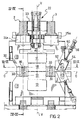
- It comprises a load-bearing structure consisting essentially of two ring-shaped frames 2, 3 arranged on opposite sides with respect to a vertical axis V of the stand passing through the median part of a strip, slab or other, being rolled; the drawings do not show graphically the product which is rolled but only a horizontal reference direction O, transverse to that of its feeding has been indicated.
- rolling stand 1 is of the pair crossing type: it is to say that on the upper and lower faces of the material to be rolled respectively act two working rolls, indicated by 10 and 12, each associated with a corresponding back up roll 11 and 13.
- the upper rolls 10 and 11 are mounted in a casing 20 wherein there are also accomodated their chocks with the respective bearings (not numbered in the drawings where they are visible only in Fig. 3 for the working roll 10); in particular, the back up roll 11 is connected to a cross-member 21 arranged transversely to the casing 20 and to which are applied its chocks (not shown in the drawings); the cross-member 21 is supported vertically by an assembly 22 of a mounting 23 which extends between the two frames 2 and 3.
- the assembly 22 in this case consists of a hydraulic cylinder with two rods hinged to the sides thereof and passing through the upper face of the casing 20, thereby meeting the cross-member 21 to which they are hinged.
- actuators 24 and 25 intended for setting the distance of the rolls 10 and 11 from the material to be rolled; such actuators comprise a fixed part 24a and 25a respectively, which will be explained in more detail hereinafter, coupled to a corresponding part 24b, 25b movable to and fro in a direction parallel to the axis V; the aforesaid movable parts 24b and 25b act on the chocks of the back up roll 11.
- the actuators 24 and 25 are per se analogous to those existing in the state of the art: differently however from what has been shown in US Patent No. 4 453 393, they are located on the roll-carrying casing 20 and not on the load-bearing structure of the stand; furthermore, their fixed parts 24a, 25a are arranged on the upper face of the casing 20 so as to be able to act against the inner surface of the frames 2 and 3 during the operation of the stand (see Figs. 2 and 4).
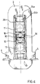
- the casing 20 has a substantially box-like shape (see Fig. 5 where, for clarity, the casing is shown with its lateral sides exploded), open towards the base where the working roll 10 is located and laterally to allow the connection of said roll with respective drive means, indicated only by a shaft 32 visible in Fig. 3; it can be observed that in the latter figure the line of intersection of the casing 20 with the plane of the drawing has been shown by cross-hatching in order to facilitate understanding of the drawing.
- the casing 20 is rotatably supported by the frames 2, 3 about the axis of rotation V; in this respect it can be seen from Figures 3 and 4 that between the casing 20 and the frames 2, 3 there is enough space to allow the rotations of the casing, which are however of limited amplitude ( ⁇ 1° - 2°).
- Such rotations are operated by two opposed thrust elements 27 and 28, mounted on the frames 2, 3.
- the casing 20 there are also located devices 30 for bending and supporting the working roll 10, consisting of normal hydraulic rams; such devices serve to push upwards the chocks of the working roll (not numbered in the drawings and visible only in Fig. 3) while the actuators 24, 25 (which push downwards) act on the chocks of the back up rolls.
- devices 30 for bending and supporting the working roll 10 consisting of normal hydraulic rams; such devices serve to push upwards the chocks of the working roll (not numbered in the drawings and visible only in Fig. 3) while the actuators 24, 25 (which push downwards) act on the chocks of the back up rolls.
- the surfaces 40 are slightly concave and orientated in such a way that their perpendiculars converge towards the axis V, which in Fig. 3 is identified by the point of intersection of the horizontal direction O with the dash-dotted line perpendicular thereto.
- the blocks 41 which are opposite to the frame 2 (those on the left in Fig. 3), are equipped with a platform 41a driven hydraulically in order to move between a retracted position wherein the platform is withdrawn into the relative block 41, and an advanced position wherein it exerts a thrust against the corresponding surface 40.
- pins 43 which are located opposite to the frame 3 of the housing, i.e. the one which is not affected by the blocks 41 with the hydraulic platform 41a mentioned above; said pins are positioned axially by an eccentric 44 of suitable dimensions and driven hydraulically (but could obviously be actuated also in other ways), in order to exert a thrusting action on a corresponding complementary appendage 45 present on the frame 3.
- the end of the pins 43 pushes against the appendage 45 which is shaped with a curved surface so that the straight line of action of their reciprocal thrust, crosses axis V.
- the rolling mill housing 1 under consideration here is moreover of the so-called "shifting" type, that is to say that its working rolls 10 and 12 are provided with the possibility of being translated along their axes.
- the wheels 50 and 51 are engaged in corresponding guide slots 52 and 53, each of which is arranged on a respective slider 54 and 55 mounted at the end of an oleodynamic thrust element 56; the latter is in turn hinged, at its end opposite to the slider, on a projection 60 of the casing 20.
- the casing 20 blocked in the structure is released by withdrawing the slacks take-up pins 43 from their advanced position, wherein they exert a thrusting action against the complementary appendage 45 associated thereto.
- the casing 20 becomes free to rotate about the axis V under the action of the thrust elements 27, 28, and the action exerted by the surfaces 40 arranged on the chamfered edges of the frames 2 and 3 with regard to the easing 20, becomes relevant: indeed the latter is guided in its rotation by said surfaces which for this reason, are orientated according to what has been explained above.
- the assembly 22 is solid in rotation with the casing 20 and is supported by the mounting 23 so as to rotate about it, which instead remains immovable being fixed to the frames 2 and 3.
- the guiding action of the aforesaid surfaces 40 makes it possible to use a reduced number of thrust elements, in this case two, to control the rotation of each casing with maximum precision and extreme simplicity; in fact, owing to this solution it is no longer necessary, as it happens in current applications, to have rigid and precise control of the movements of the thrust elements which rotate the casing, since the rotation of the latter can be guided by the aforesaid surfaces and blocks.
- the axial translation system proposed by the invention overcomes this difficulty because the various mechanisms which serve to push the roll axially, are now mounted on the casing 20 together with the roll and can therefore act independently of its angular position, since they are solid with the roll during its angular movements.
- Figure 8 One of these is referred to in Figure 8, where it is shown in a view corresponding to that of Figure 4; this variant refers to a stand generally similar to the preceding one, with the difference however that it is provided with the possibility of being able to vary the angular position of the rolls also under load, that is to say, during rolling.
- this second embodiment of the invention differs from the first one in that between the fixed parts 24a, 25a of the actuators 24, 25 and the frames 2, 3 against which the latter respectively act, there are interposed means 70 for the reduction of the horizontal friction forces which would oppose the rotational movements of the casing 20 described above, in the case where these movements took place during the rolling process, such as in the case of adjustment under load of the housing 1.
- Such means may be of the type described in British Patent Application GB-A-2 141 959 in the name of Davy McKee and already published, that is to say, a bearing containing a fluid, rollers or balls which transform the sliding friction between the frames 2, 3 and the fixed parts 24a, 25a into rolling friction, a shim made of rubber, polyurethane or some other suitable resilient material.
- the platforms 41a with the pins 43 intended for blocking and taking up slacks, to be capable of working dynamically according to predetermined patterns (for example a setting ring of force and/or position) as an alternative, or in addition, to a logic of the "on-off" type used in the case of stands without the possibility of adjustment under load.
- pairs formed by a working roll and a back up roll be used, but rolling stands could instead be envised wherein each working roll is associated with two or more support rolls.
- the assembly 22 serves essentially to retain the back up roll 11 when the working roll 10 is removed from the housing in order to be replaced.
- the rolling stand of the invention which, being of the crossed roll type, may be produced according to several alternatives, in the light of what has been stated at the beginning of this description.
- the stand of the invention can find useful application in the field both of cold and hot-rolling mills, and furthermore it may be used for rolling ferrous materials, non-ferrous materials and also non-metallic materials: consequently it should not be excluded that it may undergo modifications other than those already discussed, as a function of its wide possibilities of use.
Abstract
Description
Claims (13)
- A rolling stand for flat products, which comprises a load-bearing structure (2, 3, 4, 5), an upper working roll (10) and a lower working roll (12) rotatably supported in opposed position within said structure, at least one of them being angularly adjustable with its axis that can rotate in a plane about a reference axis (V) of the stand perpendicular thereto, at least one actuator (24, 25) acting on the adjustable roll in order to set the distance between it and the opposed roll, characterised in that the actuator (24, 25) is solid in rotation about the reference axis (V) with the angularly adjustable roll (10, 12), so as to exert on the latter an action independent of its angular position.
- A rolling stand according to Claim 1, wherein said at least one angularly adjustable working roll (10, 12) is associated with at least one back up roll (11, 13), and wherein such rolls are mounted in a casing (20) supported by the structure (2-5) of the stand in a rotatable manner with respect to said reference axis (V) and on which easing there is also located said at least one actuator (24, 25), thereby the angular adjustment of the working roll is obtained by means of the corresponding rotation of the casing about aforesaid reference axis (V).
- A rolling stand according to Claim 2, wherein the roll-carrying casing (20) is guided during its rotation by guide surfaces (40) present on the load-bearing structure (2-5) of the stand, orientated in such a way as to have the respective perpendiculars passing substantially through the reference axis (V).
- A rolling stand according to any one of Claims 2 or 3, wherein means (40, 41a; 43, 44, 45) are provided for removably blocking the roll-carrying casing (20) in the position assumed by the latter after its rotation about the reference axis (V).
- A rolling stand according to Claim 4, wherein the means for removably blocking the casing comprise a pin (43) and a corresponding complementary appendage (45) arranged one on the roll-carrying casing (20) and the other on the load-bearing structure (2, 3) of the stand, or vice versa, and wherein the pin is capable of exerting a thrust against the complementary appendage according to a line of action passing substantially through the reference axis (V) of the stand.
- A rolling stand according to Claim 4 or 5, wherein the means for the removably blocking the casing comprise a platform (41a) arranged on the roll-carrying casing (20) in a position opposed to one of the guide surfaces (40), movable to and fro between an advanced position in which it exerts a thrust on the said guide surface and a retracted position in which it is distanced therefrom.
- A rolling stand according to any one of the preceding claims, comprising means (47, 49, 50, 51, 54, 55) for axially translating said angularly adjustable working roll (10, 12), said means comprising an arm (47, 49) which extends from one end of the roll and on which there is mounted a freely rotatable wheel (50, 51) axially coplanar with the roll, said wheel being engaged with a slider (55) slidably guided by means (53, 56, 60) solid in rotation with the working roll.
- A rolling stand according to Claim 7, wherein the working roll (10, 12) is mounted in the roll-carrying casing (20) and the means (53, 56, 60) for the guided sliding of the slider (55) are arranged on the casing.
- A rolling stand according to any one of the preceding claims, wherein between said at least one actuator (24, 25) and a part (2, 3) of the load-bearing structure of the housing there are interposed means (70) for reducing the forces which oppose the rotation of the roll for its angular adjustment, during rolling.
- A rolling stand according to Claim 9 when dependent on one of Claims 4, 5 or 6, wherein the means (40, 41a; 43, 44, 45) for removably blocking the roll-carrying casing (20) are adjustable according to a setting ring of position and/or force.
- A rolling stand for flat products, which comprises a load-bearing structure (2, 3, 4, 5), an upper working roll (10) and a lower working roll (12) rotatably supported in opposed position within said structure, at least one of them being angularly adjustable with its axis which can rotate in a plane about to a reference axis (V) of the stand perpendicular thereto, at least one actuator (24, 25) acting on the adjustable roll in order to set the distance between it and the opposed roll, characterized in that it comprises means (47, 49, 50, 51, 54, 55) for axially translating said angularly adjustable working roll, and which include an arm (47, 49) extending from one end of the roll and on which there is mounted a freely rotatable wheel (50, 51) axially coplanar with the roll, said wheel being engaged with a slider (55) slidingly guided by means (53, 56, 60) that are solid in rotation about the reference axis (V) with the working roll.
- A rolling stand according to Claim 11, wherein said at least one angularly adjustable working roll (10, 12) is associated with at least one back up roll (11, 13), such rolls being mounted in a casing (20) supported by the structure (2-5) of the housing in a rotatable manner with respect to said reference axis (V) and on which casing there are located said means (53, 55, 60) for slidingly guiding the slider (55).
- A rolling mill for flat products, comprising a plurality of rolling stands according to any one of the preceding claims, located along the feeding direction of the product to be rolled.
Applications Claiming Priority (2)
| Application Number | Priority Date | Filing Date | Title |
|---|---|---|---|
| IT97MI001760A IT1293773B1 (en) | 1997-07-24 | 1997-07-24 | LAMINATION CAGE WITH CROSSED ROLLERS, WITH VARIABLE STRUCTURE. |
| ITMI971760 | 1997-07-24 |
Publications (3)
| Publication Number | Publication Date |
|---|---|
| EP0893169A2 true EP0893169A2 (en) | 1999-01-27 |
| EP0893169A3 EP0893169A3 (en) | 1999-10-20 |
| EP0893169B1 EP0893169B1 (en) | 2002-12-18 |
Family
ID=11377622
Family Applications (1)
| Application Number | Title | Priority Date | Filing Date |
|---|---|---|---|
| EP98202344A Expired - Lifetime EP0893169B1 (en) | 1997-07-24 | 1998-07-13 | Rolling stand having crossed rolls with variable setting |
Country Status (6)
| Country | Link |
|---|---|
| US (1) | US6085567A (en) |
| EP (1) | EP0893169B1 (en) |
| AT (1) | ATE229848T1 (en) |
| DE (1) | DE69810203T2 (en) |
| ES (1) | ES2186092T3 (en) |
| IT (1) | IT1293773B1 (en) |
Cited By (4)
| Publication number | Priority date | Publication date | Assignee | Title |
|---|---|---|---|---|
| WO1999056895A1 (en) * | 1998-04-30 | 1999-11-11 | Sms Demag Innse S.P.A. | Bearing for rolling stands with crossing rolls |
| WO2000012236A1 (en) * | 1998-08-28 | 2000-03-09 | Sms Demag Ag | Rolling stand with crossing back-up and/or working rolls |
| EP1281448A2 (en) * | 2001-07-30 | 2003-02-05 | Mitsubishi Heavy Industries, Ltd. | Rolling mill and rolling method |
| CN104722579A (en) * | 2015-03-20 | 2015-06-24 | 中国重型机械研究院股份公司 | Balance system for twenty-high roll mill intermediate roll |
Families Citing this family (5)
| Publication number | Priority date | Publication date | Assignee | Title |
|---|---|---|---|---|
| US6604397B2 (en) | 2001-02-05 | 2003-08-12 | Dietrich Industries, Inc. | Rollforming machine |
| EP1542815B8 (en) * | 2002-09-18 | 2009-02-18 | Bathium Canada Inc. | Lamination process and apparatus for alkali metals or alloys thereof |
| DE10243677A1 (en) * | 2002-09-20 | 2004-04-01 | Sms Demag Ag | Device for bending rollers in a multiple roller rolling mill comprises a vertical positioning unit assigned to bending blocks of one roll stand, to a plunger cylinder and to the bending blocks of the opposite-lying roll stand |
| DE102004020131A1 (en) * | 2003-12-19 | 2005-07-21 | Sms Demag Ag | Cold rolling steel mill combines three types of position shifting technology with a uniform frame design |
| DE102008009902A1 (en) * | 2008-02-19 | 2009-08-27 | Sms Demag Ag | Rolling device, in particular push roll stand |
Citations (7)
| Publication number | Priority date | Publication date | Assignee | Title |
|---|---|---|---|---|
| JPS56131004A (en) * | 1980-03-17 | 1981-10-14 | Mitsubishi Heavy Ind Ltd | Pair-cross type four-stage rolling mill |
| US4453393A (en) * | 1981-08-13 | 1984-06-12 | Mitsubishi Jukogyo Kabushiki Kaisha | Four high mill of the paired-roll-crossing type |
| JPS59110406A (en) * | 1982-12-14 | 1984-06-26 | Ishikawajima Harima Heavy Ind Co Ltd | Method and device for roll shifting |
| GB2141959A (en) * | 1983-06-23 | 1985-01-09 | Davy Mckee | Rolling mill |
| JPS60162512A (en) * | 1984-02-03 | 1985-08-24 | Mitsubishi Heavy Ind Ltd | Cross driving device of cross rolling mill |
| WO1992002320A1 (en) * | 1990-08-03 | 1992-02-20 | Davy Mckee (Poole) Limited | Twin roll casting |
| JPH04361802A (en) * | 1991-06-03 | 1992-12-15 | Ishikawajima Harima Heavy Ind Co Ltd | Cross mill |
Family Cites Families (5)
| Publication number | Priority date | Publication date | Assignee | Title |
|---|---|---|---|---|
| DE3638330A1 (en) * | 1986-11-10 | 1988-05-19 | Schloemann Siemag Ag | ROLLING DEVICES WITH A DEVICE FOR THE AXIAL SHIFTING OF ADJUSTABLE ROLLERS |
| JP2862439B2 (en) * | 1991-07-30 | 1999-03-03 | 三菱重工業株式会社 | Roll cross device of cross roll rolling mill |
| DE69209043T2 (en) * | 1991-12-27 | 1996-11-14 | Hitachi Ltd | Rolling mill, rolling process and rolling mill system |
| IT1280175B1 (en) * | 1995-05-25 | 1998-01-05 | Danieli Off Mecc | DEVICE FOR THE CROSS HANDLING OF THE LAMINATION CYLINDERS |
| IT1288933B1 (en) * | 1996-06-25 | 1998-09-25 | Danieli Off Mecc | DEVICE FOR THE CROSS HANDLING OF THE ROLLING CYLINDERS |
-
1997
- 1997-07-24 IT IT97MI001760A patent/IT1293773B1/en active IP Right Grant
-
1998
- 1998-07-13 DE DE69810203T patent/DE69810203T2/en not_active Expired - Lifetime
- 1998-07-13 EP EP98202344A patent/EP0893169B1/en not_active Expired - Lifetime
- 1998-07-13 ES ES98202344T patent/ES2186092T3/en not_active Expired - Lifetime
- 1998-07-13 AT AT98202344T patent/ATE229848T1/en active
- 1998-07-14 US US09/115,235 patent/US6085567A/en not_active Expired - Lifetime
Patent Citations (7)
| Publication number | Priority date | Publication date | Assignee | Title |
|---|---|---|---|---|
| JPS56131004A (en) * | 1980-03-17 | 1981-10-14 | Mitsubishi Heavy Ind Ltd | Pair-cross type four-stage rolling mill |
| US4453393A (en) * | 1981-08-13 | 1984-06-12 | Mitsubishi Jukogyo Kabushiki Kaisha | Four high mill of the paired-roll-crossing type |
| JPS59110406A (en) * | 1982-12-14 | 1984-06-26 | Ishikawajima Harima Heavy Ind Co Ltd | Method and device for roll shifting |
| GB2141959A (en) * | 1983-06-23 | 1985-01-09 | Davy Mckee | Rolling mill |
| JPS60162512A (en) * | 1984-02-03 | 1985-08-24 | Mitsubishi Heavy Ind Ltd | Cross driving device of cross rolling mill |
| WO1992002320A1 (en) * | 1990-08-03 | 1992-02-20 | Davy Mckee (Poole) Limited | Twin roll casting |
| JPH04361802A (en) * | 1991-06-03 | 1992-12-15 | Ishikawajima Harima Heavy Ind Co Ltd | Cross mill |
Non-Patent Citations (5)
| Title |
|---|
| PATENT ABSTRACTS OF JAPAN vol. 006, no. 010 (M-107), 21 January 1982 (1982-01-21) -& JP 56 131004 A (MITSUBISHI HEAVY IND LTD), 14 October 1981 (1981-10-14) * |
| PATENT ABSTRACTS OF JAPAN vol. 008, no. 227 (M-332), 18 October 1984 (1984-10-18) -& JP 59 110406 A (ISHIKAWAJIMA HARIMA JUKOGYO KK), 26 June 1984 (1984-06-26) * |
| PATENT ABSTRACTS OF JAPAN vol. 009, no. 330 (M-442), 25 December 1985 (1985-12-25) -& JP 60 162512 A (MITSUBISHI JUKOGYO KK), 24 August 1985 (1985-08-24) * |
| PATENT ABSTRACTS OF JAPAN vol. 017, no. 233 (M-1407), 12 May 1993 (1993-05-12) -& JP 04 361802 A (ISHIKAWAJIMA HARIMA HEAVY IND CO LTD), 15 December 1992 (1992-12-15) * |
| SHUNJI KAMADA ET AL: "EDGE PROFILE CONTROL USING PAIR CROSS MILL IN COLD ROLLING" IRON AND STEEL ENGINEER, vol. 73, no. 6, 1 June 1996 (1996-06-01), pages 20-26, XP000621621 ISSN: 0021-1559 * |
Cited By (6)
| Publication number | Priority date | Publication date | Assignee | Title |
|---|---|---|---|---|
| WO1999056895A1 (en) * | 1998-04-30 | 1999-11-11 | Sms Demag Innse S.P.A. | Bearing for rolling stands with crossing rolls |
| US6592265B1 (en) | 1998-04-30 | 2003-07-15 | Sms Demag Innse Spa | Bearing for rolling stands with crossing rolls |
| WO2000012236A1 (en) * | 1998-08-28 | 2000-03-09 | Sms Demag Ag | Rolling stand with crossing back-up and/or working rolls |
| EP1281448A2 (en) * | 2001-07-30 | 2003-02-05 | Mitsubishi Heavy Industries, Ltd. | Rolling mill and rolling method |
| EP1281448A3 (en) * | 2001-07-30 | 2005-08-17 | Mitsubishi Heavy Industries, Ltd. | Rolling mill and rolling method |
| CN104722579A (en) * | 2015-03-20 | 2015-06-24 | 中国重型机械研究院股份公司 | Balance system for twenty-high roll mill intermediate roll |
Also Published As
| Publication number | Publication date |
|---|---|
| DE69810203T2 (en) | 2003-08-28 |
| DE69810203D1 (en) | 2003-01-30 |
| EP0893169A3 (en) | 1999-10-20 |
| EP0893169B1 (en) | 2002-12-18 |
| IT1293773B1 (en) | 1999-03-10 |
| US6085567A (en) | 2000-07-11 |
| ATE229848T1 (en) | 2003-01-15 |
| ITMI971760A1 (en) | 1999-01-24 |
| ES2186092T3 (en) | 2003-05-01 |
Similar Documents
| Publication | Publication Date | Title |
|---|---|---|
| KR100245472B1 (en) | Rolling mill,rolling method and rolling mill equipment | |
| US4615202A (en) | Six-high rolling stand | |
| EP0893169B1 (en) | Rolling stand having crossed rolls with variable setting | |
| US3657913A (en) | Crown control | |
| US5765422A (en) | Device for the crossed displacement of rolling rolls | |
| RU2462323C1 (en) | System of rolls | |
| US3861190A (en) | Rolling mills | |
| JPS6232001B2 (en) | ||
| EP1005921B1 (en) | Cross rolling machine | |
| EP1082183B1 (en) | Bearing for rolling stands with crossing rolls | |
| US4414889A (en) | Rolling device | |
| JPS6317001B2 (en) | ||
| JP3334771B2 (en) | Rolling mill | |
| JP4425489B2 (en) | Multi-stage rolling mill | |
| EP0815963B1 (en) | Device for the crossed displacement of rolling rolls | |
| US5984529A (en) | Sliding bearings for chocks in rolling mill stands with crossed displacement of the rolls under load | |
| JPS6251682B2 (en) | ||
| US5921129A (en) | Device for the crossed displacement of rolling rolls | |
| JPS5831241B2 (en) | Pair-cross type 4-high rolling mill | |
| JPH04361802A (en) | Cross mill | |
| JP2740659B2 (en) | Shape control rolling mill | |
| Güttinger et al. | Maintaining flatness in cold rolling using NIPCO rolls | |
| JPH091208A (en) | Cross rolling mill | |
| GB2038218A (en) | Roll gap adjustment system for cluster mills | |
| JP2521617Y2 (en) | Rolling mill |
Legal Events
| Date | Code | Title | Description |
|---|---|---|---|
| PUAI | Public reference made under article 153(3) epc to a published international application that has entered the european phase |
Free format text: ORIGINAL CODE: 0009012 |
|
| AK | Designated contracting states |
Kind code of ref document: A2 Designated state(s): AT BE CH CY DE DK ES LI |
|
| AX | Request for extension of the european patent |
Free format text: AL;LT;LV;MK;RO;SI |
|
| PUAL | Search report despatched |
Free format text: ORIGINAL CODE: 0009013 |
|
| AK | Designated contracting states |
Kind code of ref document: A3 Designated state(s): AT BE CH CY DE DK ES FI FR GB GR IE IT LI LU MC NL PT SE |
|
| AX | Request for extension of the european patent |
Free format text: AL;LT;LV;MK;RO;SI |
|
| RIC1 | Information provided on ipc code assigned before grant |
Free format text: 6B 21B 13/02 A, 6B 21B 31/18 B |
|
| AKX | Designation fees paid | ||
| 17P | Request for examination filed |
Effective date: 20000411 |
|
| RBV | Designated contracting states (corrected) |
Designated state(s): AT BE CH CY DE DK ES LI |
|
| RBV | Designated contracting states (corrected) |
Designated state(s): AT BE DE ES FR IT NL |
|
| REG | Reference to a national code |
Ref country code: DE Ref legal event code: 8566 |
|
| GRAH | Despatch of communication of intention to grant a patent |
Free format text: ORIGINAL CODE: EPIDOS IGRA |
|
| GRAH | Despatch of communication of intention to grant a patent |
Free format text: ORIGINAL CODE: EPIDOS IGRA |
|
| GRAA | (expected) grant |
Free format text: ORIGINAL CODE: 0009210 |
|
| RAP1 | Party data changed (applicant data changed or rights of an application transferred) |
Owner name: SMS DEMAG INNSE S.P.A. |
|
| AK | Designated contracting states |
Kind code of ref document: B1 Designated state(s): AT BE DE ES FR IT NL |
|
| REF | Corresponds to: |
Ref document number: 229848 Country of ref document: AT Date of ref document: 20030115 Kind code of ref document: T |
|
| REF | Corresponds to: |
Ref document number: 69810203 Country of ref document: DE Date of ref document: 20030130 Kind code of ref document: P Ref document number: 69810203 Country of ref document: DE Date of ref document: 20030130 |
|
| REG | Reference to a national code |
Ref country code: ES Ref legal event code: FG2A Ref document number: 2186092 Country of ref document: ES Kind code of ref document: T3 |
|
| ET | Fr: translation filed | ||
| PLBE | No opposition filed within time limit |
Free format text: ORIGINAL CODE: 0009261 |
|
| STAA | Information on the status of an ep patent application or granted ep patent |
Free format text: STATUS: NO OPPOSITION FILED WITHIN TIME LIMIT |
|
| 26N | No opposition filed |
Effective date: 20030919 |
|
| PGFP | Annual fee paid to national office [announced via postgrant information from national office to epo] |
Ref country code: IT Payment date: 20120726 Year of fee payment: 15 Ref country code: DE Payment date: 20120727 Year of fee payment: 15 Ref country code: ES Payment date: 20120726 Year of fee payment: 15 Ref country code: FR Payment date: 20120731 Year of fee payment: 15 Ref country code: BE Payment date: 20120725 Year of fee payment: 15 |
|
| PGFP | Annual fee paid to national office [announced via postgrant information from national office to epo] |
Ref country code: NL Payment date: 20120724 Year of fee payment: 15 |
|
| PGFP | Annual fee paid to national office [announced via postgrant information from national office to epo] |
Ref country code: AT Payment date: 20120620 Year of fee payment: 15 |
|
| BERE | Be: lapsed |
Owner name: *SMS DEMAG INNSE S.P.A. Effective date: 20130731 |
|
| REG | Reference to a national code |
Ref country code: NL Ref legal event code: V1 Effective date: 20140201 |
|
| REG | Reference to a national code |
Ref country code: AT Ref legal event code: MM01 Ref document number: 229848 Country of ref document: AT Kind code of ref document: T Effective date: 20130713 |
|
| REG | Reference to a national code |
Ref country code: FR Ref legal event code: ST Effective date: 20140331 |
|
| PG25 | Lapsed in a contracting state [announced via postgrant information from national office to epo] |
Ref country code: DE Free format text: LAPSE BECAUSE OF NON-PAYMENT OF DUE FEES Effective date: 20140201 Ref country code: NL Free format text: LAPSE BECAUSE OF NON-PAYMENT OF DUE FEES Effective date: 20140201 Ref country code: BE Free format text: LAPSE BECAUSE OF NON-PAYMENT OF DUE FEES Effective date: 20130731 |
|
| REG | Reference to a national code |
Ref country code: DE Ref legal event code: R119 Ref document number: 69810203 Country of ref document: DE Effective date: 20140201 |
|
| PG25 | Lapsed in a contracting state [announced via postgrant information from national office to epo] |
Ref country code: IT Free format text: LAPSE BECAUSE OF NON-PAYMENT OF DUE FEES Effective date: 20130713 Ref country code: AT Free format text: LAPSE BECAUSE OF NON-PAYMENT OF DUE FEES Effective date: 20130713 Ref country code: FR Free format text: LAPSE BECAUSE OF NON-PAYMENT OF DUE FEES Effective date: 20130731 |
|
| REG | Reference to a national code |
Ref country code: ES Ref legal event code: FD2A Effective date: 20140909 |
|
| PG25 | Lapsed in a contracting state [announced via postgrant information from national office to epo] |
Ref country code: ES Free format text: LAPSE BECAUSE OF NON-PAYMENT OF DUE FEES Effective date: 20130714 |