EP0893024B1 - Video-rauschverminderung - Google Patents
Video-rauschverminderung Download PDFInfo
- Publication number
- EP0893024B1 EP0893024B1 EP97916583A EP97916583A EP0893024B1 EP 0893024 B1 EP0893024 B1 EP 0893024B1 EP 97916583 A EP97916583 A EP 97916583A EP 97916583 A EP97916583 A EP 97916583A EP 0893024 B1 EP0893024 B1 EP 0893024B1
- Authority
- EP
- European Patent Office
- Prior art keywords
- disjuncture
- pixel information
- output
- noise
- filter
- Prior art date
- Legal status (The legal status is an assumption and is not a legal conclusion. Google has not performed a legal analysis and makes no representation as to the accuracy of the status listed.)
- Expired - Lifetime
Links
- 239000003638 chemical reducing agent Substances 0.000 title abstract description 6
- 230000009467 reduction Effects 0.000 claims abstract description 27
- 230000003111 delayed effect Effects 0.000 claims description 17
- 238000000034 method Methods 0.000 claims description 14
- 238000001514 detection method Methods 0.000 claims description 10
- 230000002123 temporal effect Effects 0.000 claims description 7
- 230000008859 change Effects 0.000 claims description 6
- 230000001934 delay Effects 0.000 description 6
- 238000012935 Averaging Methods 0.000 description 5
- 238000010586 diagram Methods 0.000 description 3
- 238000013459 approach Methods 0.000 description 2
- 238000009795 derivation Methods 0.000 description 2
- 230000008569 process Effects 0.000 description 2
- 230000000007 visual effect Effects 0.000 description 2
- 230000003044 adaptive effect Effects 0.000 description 1
- 230000002238 attenuated effect Effects 0.000 description 1
- 230000002301 combined effect Effects 0.000 description 1
- 230000002596 correlated effect Effects 0.000 description 1
- 230000000694 effects Effects 0.000 description 1
- 238000001914 filtration Methods 0.000 description 1
- 238000005259 measurement Methods 0.000 description 1
- 238000012986 modification Methods 0.000 description 1
- 230000004048 modification Effects 0.000 description 1
- 238000011946 reduction process Methods 0.000 description 1
- 230000007480 spreading Effects 0.000 description 1
Images

Classifications
-
- H—ELECTRICITY
- H04—ELECTRIC COMMUNICATION TECHNIQUE
- H04N—PICTORIAL COMMUNICATION, e.g. TELEVISION
- H04N5/00—Details of television systems
- H04N5/14—Picture signal circuitry for video frequency region
- H04N5/21—Circuitry for suppressing or minimising disturbance, e.g. moiré or halo
Definitions
- This invention relates to video noise reducers and methods of noise reduction.
- a well known method for the reduction of noise in a video signal employs a recursive filter.
- the method operates by averaging similar areas in successive images and relies on the fact that the true image information in a video signal is highly correlated.
- Noise is generally random and is attenuated in the averaging process.
- a recursion constant k determines the relative weightings of the current and preceding frames in the averaging process and thus the number of frames over which effective averaging takes place.
- Significant attenuation of noise can be achieved with averaging over a relatively small number of frames.
- the present invention consists, in one aspect, in a method of noise reduction in a video signal, in which pixel information is recursively filtered to produce a noise reduced output, with recursion being disabled at a disjuncture so that pixel information after the disjuncture is not recursively combined with pixel information prior to the disjuncture, wherein, after the disjuncture, recursively filtered pixel information prior to a disjuncture continues to provide the noise reduced output, until pixel information after the disjuncture has been recursively filtered to an appropriate degree of noise reduction.
- the present invention consists in a video noise reduction filter comprising a temporal recursive filter; means for disabling recursion in the temporal recursive filter on detection of a disjuncture so that pixel information after the disjuncture is not recursively combined with pixel information prior to the disjuncture; a delay path affording multiple filter outputs mutually delayed by picture intervals; and means for selecting between said filter outputs on detection of a disjuncture so that recursively filtered pixel information prior to a disjuncture continues to provide the noise reduced output, until pixel information after the disjuncture has been recursively filtered to an appropriate degree of noise reduction.
- the present invention recognises that, taking the example of a shot change, the visually disturbing effect of replacing a quiet, heavily noise-reduced shot by the first noisy field of a new shot can be avoided by delaying showing the new shot until sufficient fields have been recursively filtered for the noise level on the new shot to have approached or equalled that of the current shot.
- the same approach applies of course pixel-by-pixel in the face of motion.
- a subtractor 10 serves to derive the difference between the input video signal at terminal 12 and the signal at the output 14 of the filter, delayed by one frame in delay 16.
- the frame difference signal which is output by the subtractor 10 passes through a multiplier 18, the coefficient k of which is generated in noise measurement system and control block 20 which receives the frame difference signal as an input.
- the rectified and filtered difference between the incoming signal and the frame delayed output of the filter is taken as a measure of motion.
- the signal passing through multiplier 18 is added in adder 22 to the output of frame delay 16 to derive the filter output on terminal 14.
- the circuit of Figure 1 serves, for each pixel, to add to the filter output in the previous frame, k times the difference between the current pixel and the filter output in the previous frame.
- k the difference between the current pixel and the filter output in the previous frame.
- the filter output in that example will comprise 50% of the current frame, 25% of the preceding frame, 12.5% of the next preceding frame and so on. If motion is detected, that is to say the frame difference signal output from subtractor 10 exceeds a predetermined threshold, the value of k is set to unity.
- the combined effect of subtractor 10 and adder 22 is then first to subtract and then to add the filter output from the preceding frame leaving only information from the current frame. Setting the value of k to unity accordingly disables the recursion.
- an object 50 is depicted as moving in position between frame i and frame i+1 .
- a motion signal k is illustrated, being the rectified difference between frame i and frame i+1 . It will be seen that the value of k goes high at the leading edge of the object in frame i and falls at the leading edge of the object in frame i+1 . Similarly, the value of k goes high at the trailing edge of the object in frame i and falls at the trailing edge of the object in frame i+1 . It will be understood that during the intervals over which the value of k is high, the recursive noise reduction is disabled. There are thus created regions in the picture at the edges of the moving object at which there is no noise reduction. These regions are shown for frame i+1 at a and b .
- Whist the motion signal k has been depicted as simply the rectified frame difference, it has been customary to filter the motion signal, causing spatial spreading.
- the derivation of k embodies this approach.
- successive outputs of a recursive filter might be:- a : a + b 2 : a + b + c 3 : a + b + c + d 4
- the visual effect of increased noise in e is avoided by introducing a picture interval delay or delays and continuing to output:- a + b + c + d 4 until the recursive filter has produced an output following the disjuncture, which is appropriately noise reduced, for example:- e + f + g + h 4
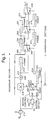
- FIG. 3 An example of a noise reducer according to the invention will now be described with reference to Figure 3. It will be seen that the left-hand portion of the circuit, marked “recursive section”, corresponds generally to the previously described temporal noise reduction filter. It will accordingly not be necessary to describe again the function of subtractor 210, multiplier 218, adder 222 and frame delay 216.
- derivation of the signal k is performed in two stages.
- a motion detector block 250 receives the output from subtractor 210 and carries out appropriate filtering.
- a motion detection signal is then passed to one input of a motion control block 252, one function of this block being to provide a k signal having the properties discussed above, by which the correct proportions are maintained in the recursion to optimise noise reduction.
- the motion control block 252 additionally derives a signal m . The function of which will be described later.
- the right-hand section of Figure 3 comprises a switched delay line giving up to three frames of delay.
- the frame delay 216 of the recursive section doubles as the first frame delay in a transversal section and there are additional frame delays 256 and 251.
- Switches 260, 262 and 269 are provided to select appropriate outputs from the frame delay path.
- Switch 260 selects between the output 214 of the recursive noise reduction filter and the point 266 of the output from the frame delay 216.
- the switch 262 selects between the output of the switch 260 and the point 268 intermediate between frame delays 256 and 251.
- Switch 269 switches between the output of switch 262 and the point 270 at the output of frame delay 251.
- the control input of switch 260 is the signal m from the motion control block 252. This signal passes through frame delays 272 and 274 to provide the control inputs for switches 262 and 269 respectively.
- the frame delays 216, 256 and 251 may be regarded as a picture-interval delay path affording, through the switches 260, 262 and 269 picture delayed outputs from the recursive filter.
- each of the switches selects between the quietest of its two inputs.
- the next switch can choose between the previous delayed output, and the output of the first switch. If the first switch is currently selecting the stored output, then the second switch is offered delayed versions of the signals offered to the first switch, and so it can use a delayed version of the same decision ( m ). On the other hand, if the first is currently selecting the nondelayed output (because it is quieter than the delayed output) then the second switch should ideally remake the decision using a lower threshold. However, since the threshold is not really critical, satisfactory results are obtained by simply using the original decision ( m ) delayed by one frame in both cases. Similarly, subsequent switches can also be controlled by delayed versions of m . The slight error introduced by this simplification can be reduced on average by using a slightly lower threshold to generate m .
- the motion control block can be implemented in many ways. The simplest is probably a PROM containing pre-computed output values for all combinations of its inputs.
- the previous notation will be employed of successive pixel values a, b, c, d ... separated by a picture interval, with a disjuncture such as a shot change occurring between d and e .
- the signal appearing at critical locations are shown in the following table:- 214 266 268 270 m 260 262 out a a z y x 1 z ? ? b a+b / 2 a z y 0 a+b / 2 z ?
Landscapes
- Engineering & Computer Science (AREA)
- Multimedia (AREA)
- Signal Processing (AREA)
- Picture Signal Circuits (AREA)
- Transforming Electric Information Into Light Information (AREA)
- Polyurethanes Or Polyureas (AREA)
- Transforming Light Signals Into Electric Signals (AREA)
Claims (9)
- Verfahren zur Rausch- bzw. Störungsverminderung in einem Videosignal, bei dem Pixel-Informationen rekursiv bzw. wiederholbar gefiltert werden, um einen störungs- bzw. rauschreduzierten Ausgang zu erzeugen, wobei die Rekursion bei einer Unterbrechung gesperrt wird, so dass Pixel- bzw. Bildelementinformationen nach der Unterbrechung nicht rekursiv bzw. wiederholbar mit Pixel- bzw. Bildinformationen vor der Unterbrechung kombiniert werden, wobei nach der Unterbrechung rekursiv gefilterte Pixel- bzw. Bildelementinformationen vor einer Unterbrechung fortfahren, den rausch- bzw. störungsreduzierten Ausgang zur Verfügung zu stellen, bis Pixel- bzw. Bildinformationen nach der Unterbrechung rekursiv bis zu einem passenden bzw. geeigneten Grad der Rausch- bzw. Störungsverringerung gefiltert worden sind.
- Verfahren nach Anspruch 1, wobei der Ausgang eines rekursiven Filters an eine Bildintervallverzögerungskette angelegt wird und der Erfassung einer Unterbrechung unter Sperrung der Rekursion folgend eine Auswahl zwischen bildintervallverzögerten Filterausgängen durchgeführt wird.
- Verfahren nach einem der Ansprüche 1 oder 2, wobei bei der Erfassung einer Unterbrechung in der Form eines Bildwechsels von einem ersten Bild zu einem zweiten Bild die Ausgabe von Feldern von dem zweiten Bild verzögert wird, bis ausreichend Felder rekursiv gefiltert worden sind, um den Störungs- bzw. Rauschpegel auf dem zweiten Bild rekursiv näherungsweise auf den des ersten reduziert zu haben.
- Verfahren nach einem der Ansprüche 1 oder 2, wobei bei der Erfassung einer Unterbrechung in der Form einer Bewegung die Ausgabe von Pixeln bzw. Bildelementen, die nach der Unterbrechung erscheinen, verzögert wird, bis ausreichend Pixel bzw. Bildelemente rekursiv gefiltert worden sind, um den Störungs- bzw. Rauschpegel nach der Unterbrechung auf näherungsweise den vor der Unterbrechung reduziert zu haben.
- Verfahren nach einem der vorangehenden Ansprüche, wobei die Rekursion so nach einer Unterbrechung gesteuert wird, dass verfügbare Pixel bzw. Bildelemente gleichermassen zu dem Filterausgang beitragen.
- Verfahren nach Anspruch 5, in dem die Rekursionskonstante in Abhängigkeit von der Zahl der Bildintervalle seit einer Unterbrechung verändert wird, was zu einer Sperrung der Rekursion führt.
- Verfahren nach einem der Ansprüche 1 bis 4, wobei die Rekursionskonstante nach einer Unterbrechung in Abhängigkeit von der Zahl der Bildintervalle seit der Unterbrechung verändert wird, um den Ausgangsrausch- bzw. -Störungspegel zu minimieren.
- Videorausch bzw. -Störungsverringerungsfilter, der aufweist, einen temporären Rekursionsfilter; Mittel zum Sperren der Rekursion in dem temporären Rekursionsfilter bei Erfassung einer Unterbrechung, so dass Pixel- bzw. Bildelementinformationen nach der Unterbrechung nicht mit Pixel- bzw. Bildelementinformationen vor der Unterbrechung rekursiv kombiniert werden; einen Verzögerungspfad, der mehrere Filterausgänge aufbringt, die gegenseitig um Bildintervalle verzögert sind; und Mittel, um zwischen den Filterausgängen bei Erfassung einer Unterbrechung auszuwählen, so dass rekursiv gefilterte Pixel- bzw. Bildelementinformationen vor einer Unterbrechung fortfahren, einen störungs- bzw. rauschverringerten Ausgang zur Verfügung zu stellen, bis Bildelementinformationen nach der Unterbrechung rekursiv bis zu einem passenden bzw. angemessenen Grad der Störungs- bzw. Rauschverringerung gefiltert worden sind.
- Videorausch- bzw. Störungsverringerungsfilter gemäß Anspruch 8, wobei die Mittel zum Auswählen zwischen mehreren Filterausgängen dazu dienen, den Ausgang auszuwählen, der den minimalen Störungs- bzw. Rauschpegel hat.
Applications Claiming Priority (3)
| Application Number | Priority Date | Filing Date | Title |
|---|---|---|---|
| GB9607668 | 1996-04-12 | ||
| GBGB9607668.2A GB9607668D0 (en) | 1996-04-12 | 1996-04-12 | Video noise reducer |
| PCT/GB1997/001049 WO1997039572A1 (en) | 1996-04-12 | 1997-04-14 | Video noise reducer |
Publications (2)
| Publication Number | Publication Date |
|---|---|
| EP0893024A1 EP0893024A1 (de) | 1999-01-27 |
| EP0893024B1 true EP0893024B1 (de) | 2000-06-28 |
Family
ID=10792004
Family Applications (1)
| Application Number | Title | Priority Date | Filing Date |
|---|---|---|---|
| EP97916583A Expired - Lifetime EP0893024B1 (de) | 1996-04-12 | 1997-04-14 | Video-rauschverminderung |
Country Status (9)
| Country | Link |
|---|---|
| US (1) | US6259489B1 (de) |
| EP (1) | EP0893024B1 (de) |
| JP (1) | JP3899129B2 (de) |
| AT (1) | ATE194255T1 (de) |
| AU (1) | AU722673B2 (de) |
| CA (1) | CA2249532A1 (de) |
| DE (1) | DE69702393T2 (de) |
| GB (1) | GB9607668D0 (de) |
| WO (1) | WO1997039572A1 (de) |
Families Citing this family (39)
| Publication number | Priority date | Publication date | Assignee | Title |
|---|---|---|---|---|
| US6310982B1 (en) | 1998-11-12 | 2001-10-30 | Oec Medical Systems, Inc. | Method and apparatus for reducing motion artifacts and noise in video image processing |
| IL134182A (en) | 2000-01-23 | 2006-08-01 | Vls Com Ltd | Method and apparatus for visual lossless pre-processing |
| AU2654000A (en) * | 2000-02-17 | 2001-08-27 | University Of British Columbia, The | Noise reduction for video signals |
| US6735561B1 (en) * | 2000-03-29 | 2004-05-11 | At&T Corp. | Effective deployment of temporal noise shaping (TNS) filters |
| US6753929B1 (en) | 2000-06-28 | 2004-06-22 | Vls Com Ltd. | Method and system for real time motion picture segmentation and superposition |
| JP2002216403A (ja) * | 2001-01-16 | 2002-08-02 | Canon Inc | 光磁気ディスクのアニール方法、及び光磁気ディスク |
| US6718069B2 (en) * | 2001-02-22 | 2004-04-06 | Varian Medical Systems, Inc. | Method and system for reducing correlated noise in image data |
| EP1251463A1 (de) * | 2001-04-20 | 2002-10-23 | BTS Media Solutions GmbH | Anordnung zur Verarbeitung von Videosignalen |
| KR100396557B1 (ko) * | 2001-10-11 | 2003-09-02 | 삼성전자주식회사 | 영상 신호의 노이즈 감쇄 방법 및 그 장치 |
| KR100429804B1 (ko) * | 2001-12-29 | 2004-05-03 | 삼성전자주식회사 | 적응적 영상 노이즈 감쇄 장치 및 그 방법 |
| GB2390772B (en) | 2002-07-12 | 2005-12-07 | Snell & Wilcox Ltd | Improved noise reduction |
| FR2860941A1 (fr) * | 2003-10-14 | 2005-04-15 | Nextream France | Dispositif et procede d'estimation de bruit d'un signal video |
| US7095028B2 (en) * | 2003-10-15 | 2006-08-22 | Varian Medical Systems | Multi-slice flat panel computed tomography |
| US7589326B2 (en) * | 2003-10-15 | 2009-09-15 | Varian Medical Systems Technologies, Inc. | Systems and methods for image acquisition |
| EP1526740A1 (de) * | 2003-10-21 | 2005-04-27 | Deutsche Thomson-Brandt Gmbh | Verfahren und Vorrichtung zur rekursiven Verminderung des Chrominanzrauschens |
| US7317841B2 (en) * | 2003-12-22 | 2008-01-08 | Ge Medical Systems Global Technology Company, Llc | System and method for image noise reduction using a minimal error spatiotemporal recursive filter |
| US8401069B2 (en) * | 2004-04-05 | 2013-03-19 | Snell Limited | Apparatus and process for re-timing video cuts |
| KR100624421B1 (ko) | 2004-05-04 | 2006-09-19 | 삼성전자주식회사 | 디지탈 영상 신호 필터링 장치 및 방법 |
| US7903902B2 (en) * | 2004-07-26 | 2011-03-08 | Sheraizin Semion M | Adaptive image improvement |
| CA2616871A1 (en) * | 2004-07-30 | 2006-02-02 | Algolith Inc. | Apparatus and method for adaptive 3d noise reduction |
| US7526142B2 (en) * | 2005-02-22 | 2009-04-28 | Sheraizin Vitaly S | Enhancement of decompressed video |
| JP2006287632A (ja) * | 2005-03-31 | 2006-10-19 | Pioneer Electronic Corp | ノイズ低減装置およびノイズ低減方法 |
| US7535517B2 (en) * | 2005-04-14 | 2009-05-19 | Samsung Electronics Co., Ltd. | Method of motion compensated temporal noise reduction |
| JP4649355B2 (ja) * | 2006-03-27 | 2011-03-09 | 富士通株式会社 | ブロックノイズ検出方法及び装置並びにブロックノイズ低減方法及び装置 |
| JP2007274067A (ja) * | 2006-03-30 | 2007-10-18 | Mitsubishi Electric Corp | ノイズ除去装置、ノイズ除去方法、および映像信号表示装置 |
| GB2438660B (en) * | 2006-06-02 | 2011-03-30 | Tandberg Television Asa | Recursive filter system for a video signal |
| NO326285B1 (no) | 2006-07-19 | 2008-11-03 | Tandberg Telecom As | Fremgangsmate for stoyreduksjon av et videobilde |
| CN101658027B (zh) | 2007-03-31 | 2013-04-10 | 索尼德国有限责任公司 | 用于图像帧的降噪方法和单元 |
| TWI401944B (zh) * | 2007-06-13 | 2013-07-11 | Novatek Microelectronics Corp | 用於視訊處理系統之雜訊消除裝置 |
| TW200901751A (en) * | 2007-06-20 | 2009-01-01 | Sunplus Technology Co Ltd | System and method for estimating noise in a video frame |
| TW200906170A (en) * | 2007-07-18 | 2009-02-01 | Sunplus Technology Co Ltd | Image noise estimation system and method |
| US8237868B2 (en) | 2009-03-30 | 2012-08-07 | Sharp Laboratories Of America, Inc. | Systems and methods for adaptive spatio-temporal filtering for image and video upscaling, denoising and sharpening |
| US8755625B2 (en) | 2010-11-19 | 2014-06-17 | Analog Devices, Inc. | Component filtering for low-light noise reduction |
| US20120128244A1 (en) * | 2010-11-19 | 2012-05-24 | Raka Singh | Divide-and-conquer filter for low-light noise reduction |
| US9510018B2 (en) | 2011-11-23 | 2016-11-29 | Luca Rossato | Signal analysis and generation of transient information |
| CN104115482B (zh) * | 2012-10-04 | 2017-11-21 | 松下电器(美国)知识产权公司 | 图像噪声除去装置、以及图像噪声除去方法 |
| US20140192266A1 (en) * | 2013-01-04 | 2014-07-10 | Qualcomm Incorporated | Method and apparatus of reducing compression noise in digital video streams |
| GB2583519B (en) | 2019-05-02 | 2021-12-08 | Apical Ltd | Image processing |
| US20230113786A1 (en) * | 2021-10-13 | 2023-04-13 | SparkCognition, Inc. | Artifact reduction for solutions to inverse problems |
Family Cites Families (13)
| Publication number | Priority date | Publication date | Assignee | Title |
|---|---|---|---|---|
| US4064530A (en) * | 1976-11-10 | 1977-12-20 | Cbs Inc. | Noise reduction system for color television |
| EP0004728B1 (de) * | 1978-04-03 | 1982-04-28 | British Broadcasting Corporation | Rauschverminderung in elektrischen Signalen |
| FR2575886B1 (fr) | 1985-01-04 | 1987-02-20 | Thomson Csf | Procede pour reduire la visibilite du bruit dans une suite d'images video et dispositif pour la mise en oeuvre de ce procede |
| US4639784A (en) * | 1985-02-19 | 1987-01-27 | Rca Corporation | Video signal recursive filter adaptively controlled responsive to the history of image motion |
| US4737850A (en) * | 1985-07-03 | 1988-04-12 | Rca Corporation | Apparatus for noise reducing composite video signal |
| JP2782766B2 (ja) * | 1989-03-22 | 1998-08-06 | キヤノン株式会社 | 動画静止画変換方法 |
| US5025316A (en) * | 1989-11-06 | 1991-06-18 | North American Philips Corporation | Video noise reduction system with measured noise input |
| DE4031785C2 (de) * | 1990-10-08 | 1996-07-04 | Broadcast Television Syst | Verfahren zur Reduktion von Rauschen in Videosignalen |
| US5185664A (en) * | 1991-10-31 | 1993-02-09 | North American Philips Corporation | Method and apparatus for combining field and frame recursive noise reduction for video signals |
| DE4137404C2 (de) * | 1991-11-14 | 1997-07-10 | Philips Broadcast Television S | Verfahren zur Reduktion von Rauschen |
| EP0578311B1 (de) | 1992-07-10 | 1998-12-09 | Koninklijke Philips Electronics N.V. | Röntgendurchleuchtungsgerät mit Mitteln zur Rauschreduktion |
| JPH06121192A (ja) * | 1992-10-08 | 1994-04-28 | Sony Corp | ノイズ除去回路 |
| US5499057A (en) * | 1993-08-27 | 1996-03-12 | Sony Corporation | Apparatus for producing a noise-reducded image signal from an input image signal |
-
1996
- 1996-04-12 GB GBGB9607668.2A patent/GB9607668D0/en active Pending
-
1997
- 1997-04-14 DE DE69702393T patent/DE69702393T2/de not_active Expired - Lifetime
- 1997-04-14 AT AT97916583T patent/ATE194255T1/de not_active IP Right Cessation
- 1997-04-14 AU AU25191/97A patent/AU722673B2/en not_active Ceased
- 1997-04-14 US US09/171,128 patent/US6259489B1/en not_active Expired - Lifetime
- 1997-04-14 EP EP97916583A patent/EP0893024B1/de not_active Expired - Lifetime
- 1997-04-14 WO PCT/GB1997/001049 patent/WO1997039572A1/en not_active Ceased
- 1997-04-14 JP JP53686997A patent/JP3899129B2/ja not_active Expired - Fee Related
- 1997-04-14 CA CA002249532A patent/CA2249532A1/en not_active Abandoned
Also Published As
| Publication number | Publication date |
|---|---|
| DE69702393D1 (de) | 2000-08-03 |
| GB9607668D0 (en) | 1996-06-12 |
| CA2249532A1 (en) | 1997-10-23 |
| US6259489B1 (en) | 2001-07-10 |
| AU2519197A (en) | 1997-11-07 |
| JP2000508851A (ja) | 2000-07-11 |
| WO1997039572A1 (en) | 1997-10-23 |
| DE69702393T2 (de) | 2001-02-01 |
| EP0893024A1 (de) | 1999-01-27 |
| AU722673B2 (en) | 2000-08-10 |
| JP3899129B2 (ja) | 2007-03-28 |
| ATE194255T1 (de) | 2000-07-15 |
Similar Documents
| Publication | Publication Date | Title |
|---|---|---|
| AU722673B2 (en) | Video noise reducer | |
| EP0592196B1 (de) | Schaltungen zur Rauschunterdrückung | |
| US4058836A (en) | Noise reduction in television signals | |
| US5446501A (en) | Three-dimensional median and recursive filtering apparatus and method for video image enhancement | |
| EP0502615B1 (de) | Verfahren zur Bewegungsfeststellung eines Videosignals und Störbegrenzer mit Einsatz dieser Verfahren | |
| KR960008061B1 (ko) | 비디오 신호용 잡음 감소 장치 | |
| EP0175736B1 (de) | Gerät das einen bewegungsdetektor umfasst, zur verarbeitung eines fernsehsignals | |
| KR100367512B1 (ko) | 움직임적응비디오잡음감소시스템 | |
| KR0140226B1 (ko) | 잡음 제거회로 | |
| KR100230254B1 (ko) | 잡음 감소 회로 | |
| US20040125236A1 (en) | Video noise floor estimator with impulse noise detection | |
| US4562470A (en) | Electrical noise reducer for T.V. signals | |
| US5099329A (en) | Noise reduction method and device for image signal | |
| KR950003035B1 (ko) | 영상신호의 천이영역 강조장치 및 방법 | |
| KR930003566B1 (ko) | 화질 조정회로 | |
| US5978047A (en) | Blemish concealment in video signals | |
| US5519453A (en) | Method of eliminating interfernce signals from video signals | |
| KR940017737A (ko) | 잡음 제거 필터 및 방법과 영상 신호 수상기 | |
| EP0182294B1 (de) | Schaltung zur Bearbeitung von Videosignalen | |
| JPH09312788A (ja) | 雑音低減回路 | |
| FI95638B (fi) | Kytkentäjärjestely televisiokuvan terävyyden korostamiseksi ja kohinan vaimentamiseksi | |
| JP3424372B2 (ja) | 雑音低減装置 | |
| JP2000134510A (ja) | 映像信号のノイズ除去回路 | |
| JP3115047B2 (ja) | 画像用ノイズ低減回路 | |
| JP2862700B2 (ja) | 動き検出装置 |
Legal Events
| Date | Code | Title | Description |
|---|---|---|---|
| PUAI | Public reference made under article 153(3) epc to a published international application that has entered the european phase |
Free format text: ORIGINAL CODE: 0009012 |
|
| 17P | Request for examination filed |
Effective date: 19980924 |
|
| AK | Designated contracting states |
Kind code of ref document: A1 Designated state(s): AT BE CH DE DK ES FR GB IE IT LI NL SE |
|
| 17Q | First examination report despatched |
Effective date: 19990210 |
|
| GRAG | Despatch of communication of intention to grant |
Free format text: ORIGINAL CODE: EPIDOS AGRA |
|
| GRAG | Despatch of communication of intention to grant |
Free format text: ORIGINAL CODE: EPIDOS AGRA |
|
| GRAH | Despatch of communication of intention to grant a patent |
Free format text: ORIGINAL CODE: EPIDOS IGRA |
|
| GRAH | Despatch of communication of intention to grant a patent |
Free format text: ORIGINAL CODE: EPIDOS IGRA |
|
| GRAA | (expected) grant |
Free format text: ORIGINAL CODE: 0009210 |
|
| AK | Designated contracting states |
Kind code of ref document: B1 Designated state(s): AT BE CH DE DK ES FR GB IE IT LI NL SE |
|
| PG25 | Lapsed in a contracting state [announced via postgrant information from national office to epo] |
Ref country code: LI Free format text: LAPSE BECAUSE OF FAILURE TO SUBMIT A TRANSLATION OF THE DESCRIPTION OR TO PAY THE FEE WITHIN THE PRESCRIBED TIME-LIMIT Effective date: 20000628 Ref country code: ES Free format text: THE PATENT HAS BEEN ANNULLED BY A DECISION OF A NATIONAL AUTHORITY Effective date: 20000628 Ref country code: CH Free format text: LAPSE BECAUSE OF FAILURE TO SUBMIT A TRANSLATION OF THE DESCRIPTION OR TO PAY THE FEE WITHIN THE PRESCRIBED TIME-LIMIT Effective date: 20000628 Ref country code: BE Free format text: LAPSE BECAUSE OF FAILURE TO SUBMIT A TRANSLATION OF THE DESCRIPTION OR TO PAY THE FEE WITHIN THE PRESCRIBED TIME-LIMIT Effective date: 20000628 Ref country code: AT Free format text: LAPSE BECAUSE OF FAILURE TO SUBMIT A TRANSLATION OF THE DESCRIPTION OR TO PAY THE FEE WITHIN THE PRESCRIBED TIME-LIMIT Effective date: 20000628 |
|
| REF | Corresponds to: |
Ref document number: 194255 Country of ref document: AT Date of ref document: 20000715 Kind code of ref document: T |
|
| REG | Reference to a national code |
Ref country code: CH Ref legal event code: EP |
|
| REG | Reference to a national code |
Ref country code: IE Ref legal event code: FG4D |
|
| REF | Corresponds to: |
Ref document number: 69702393 Country of ref document: DE Date of ref document: 20000803 |
|
| ITF | It: translation for a ep patent filed | ||
| ET | Fr: translation filed | ||
| PG25 | Lapsed in a contracting state [announced via postgrant information from national office to epo] |
Ref country code: SE Free format text: LAPSE BECAUSE OF FAILURE TO SUBMIT A TRANSLATION OF THE DESCRIPTION OR TO PAY THE FEE WITHIN THE PRESCRIBED TIME-LIMIT Effective date: 20000928 Ref country code: DK Free format text: LAPSE BECAUSE OF FAILURE TO SUBMIT A TRANSLATION OF THE DESCRIPTION OR TO PAY THE FEE WITHIN THE PRESCRIBED TIME-LIMIT Effective date: 20000928 |
|
| REG | Reference to a national code |
Ref country code: CH Ref legal event code: PL |
|
| PG25 | Lapsed in a contracting state [announced via postgrant information from national office to epo] |
Ref country code: IE Free format text: LAPSE BECAUSE OF NON-PAYMENT OF DUE FEES Effective date: 20010416 |
|
| PLBE | No opposition filed within time limit |
Free format text: ORIGINAL CODE: 0009261 |
|
| STAA | Information on the status of an ep patent application or granted ep patent |
Free format text: STATUS: NO OPPOSITION FILED WITHIN TIME LIMIT |
|
| PGFP | Annual fee paid to national office [announced via postgrant information from national office to epo] |
Ref country code: NL Payment date: 20010430 Year of fee payment: 5 |
|
| 26N | No opposition filed | ||
| REG | Reference to a national code |
Ref country code: GB Ref legal event code: IF02 |
|
| REG | Reference to a national code |
Ref country code: IE Ref legal event code: MM4A |
|
| PG25 | Lapsed in a contracting state [announced via postgrant information from national office to epo] |
Ref country code: NL Free format text: LAPSE BECAUSE OF NON-PAYMENT OF DUE FEES Effective date: 20021101 |
|
| NLV4 | Nl: lapsed or anulled due to non-payment of the annual fee |
Effective date: 20021101 |
|
| PG25 | Lapsed in a contracting state [announced via postgrant information from national office to epo] |
Ref country code: IT Free format text: LAPSE BECAUSE OF NON-PAYMENT OF DUE FEES;WARNING: LAPSES OF ITALIAN PATENTS WITH EFFECTIVE DATE BEFORE 2007 MAY HAVE OCCURRED AT ANY TIME BEFORE 2007. THE CORRECT EFFECTIVE DATE MAY BE DIFFERENT FROM THE ONE RECORDED. Effective date: 20050414 |
|
| PGFP | Annual fee paid to national office [announced via postgrant information from national office to epo] |
Ref country code: DE Payment date: 20120420 Year of fee payment: 16 |
|
| PGFP | Annual fee paid to national office [announced via postgrant information from national office to epo] |
Ref country code: FR Payment date: 20120419 Year of fee payment: 16 |
|
| PG25 | Lapsed in a contracting state [announced via postgrant information from national office to epo] |
Ref country code: DE Free format text: LAPSE BECAUSE OF NON-PAYMENT OF DUE FEES Effective date: 20131101 |
|
| REG | Reference to a national code |
Ref country code: FR Ref legal event code: ST Effective date: 20131231 |
|
| REG | Reference to a national code |
Ref country code: DE Ref legal event code: R119 Ref document number: 69702393 Country of ref document: DE Effective date: 20131101 |
|
| PG25 | Lapsed in a contracting state [announced via postgrant information from national office to epo] |
Ref country code: FR Free format text: LAPSE BECAUSE OF NON-PAYMENT OF DUE FEES Effective date: 20130430 |
|
| PGFP | Annual fee paid to national office [announced via postgrant information from national office to epo] |
Ref country code: GB Payment date: 20160427 Year of fee payment: 20 |
|
| REG | Reference to a national code |
Ref country code: GB Ref legal event code: PE20 Expiry date: 20170413 |
|
| PG25 | Lapsed in a contracting state [announced via postgrant information from national office to epo] |
Ref country code: GB Free format text: LAPSE BECAUSE OF EXPIRATION OF PROTECTION Effective date: 20170413 |