EP0892985B1 - Transport device for flat objects and process of transfer of these objects between the device and a treatment apparatus - Google Patents
Transport device for flat objects and process of transfer of these objects between the device and a treatment apparatus Download PDFInfo
- Publication number
- EP0892985B1 EP0892985B1 EP97919462A EP97919462A EP0892985B1 EP 0892985 B1 EP0892985 B1 EP 0892985B1 EP 97919462 A EP97919462 A EP 97919462A EP 97919462 A EP97919462 A EP 97919462A EP 0892985 B1 EP0892985 B1 EP 0892985B1
- Authority
- EP
- European Patent Office
- Prior art keywords
- module
- door
- flange
- machine
- modules
- Prior art date
- Legal status (The legal status is an assumption and is not a legal conclusion. Google has not performed a legal analysis and makes no representation as to the accuracy of the status listed.)
- Expired - Lifetime
Links
Images


Classifications
-
- H—ELECTRICITY
- H01—ELECTRIC ELEMENTS
- H01L—SEMICONDUCTOR DEVICES NOT COVERED BY CLASS H10
- H01L21/00—Processes or apparatus adapted for the manufacture or treatment of semiconductor or solid state devices or of parts thereof
- H01L21/67—Apparatus specially adapted for handling semiconductor or electric solid state devices during manufacture or treatment thereof; Apparatus specially adapted for handling wafers during manufacture or treatment of semiconductor or electric solid state devices or components ; Apparatus not specifically provided for elsewhere
- H01L21/677—Apparatus specially adapted for handling semiconductor or electric solid state devices during manufacture or treatment thereof; Apparatus specially adapted for handling wafers during manufacture or treatment of semiconductor or electric solid state devices or components ; Apparatus not specifically provided for elsewhere for conveying, e.g. between different workstations
- H01L21/67739—Apparatus specially adapted for handling semiconductor or electric solid state devices during manufacture or treatment thereof; Apparatus specially adapted for handling wafers during manufacture or treatment of semiconductor or electric solid state devices or components ; Apparatus not specifically provided for elsewhere for conveying, e.g. between different workstations into and out of processing chamber
- H01L21/67757—Apparatus specially adapted for handling semiconductor or electric solid state devices during manufacture or treatment thereof; Apparatus specially adapted for handling wafers during manufacture or treatment of semiconductor or electric solid state devices or components ; Apparatus not specifically provided for elsewhere for conveying, e.g. between different workstations into and out of processing chamber vertical transfer of a batch of workpieces
-
- H—ELECTRICITY
- H01—ELECTRIC ELEMENTS
- H01L—SEMICONDUCTOR DEVICES NOT COVERED BY CLASS H10
- H01L21/00—Processes or apparatus adapted for the manufacture or treatment of semiconductor or solid state devices or of parts thereof
- H01L21/67—Apparatus specially adapted for handling semiconductor or electric solid state devices during manufacture or treatment thereof; Apparatus specially adapted for handling wafers during manufacture or treatment of semiconductor or electric solid state devices or components ; Apparatus not specifically provided for elsewhere
- H01L21/673—Apparatus specially adapted for handling semiconductor or electric solid state devices during manufacture or treatment thereof; Apparatus specially adapted for handling wafers during manufacture or treatment of semiconductor or electric solid state devices or components ; Apparatus not specifically provided for elsewhere using specially adapted carriers or holders; Fixing the workpieces on such carriers or holders
- H01L21/6735—Closed carriers
- H01L21/67353—Closed carriers specially adapted for a single substrate
-
- H—ELECTRICITY
- H01—ELECTRIC ELEMENTS
- H01L—SEMICONDUCTOR DEVICES NOT COVERED BY CLASS H10
- H01L21/00—Processes or apparatus adapted for the manufacture or treatment of semiconductor or solid state devices or of parts thereof
- H01L21/67—Apparatus specially adapted for handling semiconductor or electric solid state devices during manufacture or treatment thereof; Apparatus specially adapted for handling wafers during manufacture or treatment of semiconductor or electric solid state devices or components ; Apparatus not specifically provided for elsewhere
- H01L21/673—Apparatus specially adapted for handling semiconductor or electric solid state devices during manufacture or treatment thereof; Apparatus specially adapted for handling wafers during manufacture or treatment of semiconductor or electric solid state devices or components ; Apparatus not specifically provided for elsewhere using specially adapted carriers or holders; Fixing the workpieces on such carriers or holders
- H01L21/6735—Closed carriers
- H01L21/67379—Closed carriers characterised by coupling elements, kinematic members, handles or elements to be externally gripped
-
- H—ELECTRICITY
- H01—ELECTRIC ELEMENTS
- H01L—SEMICONDUCTOR DEVICES NOT COVERED BY CLASS H10
- H01L21/00—Processes or apparatus adapted for the manufacture or treatment of semiconductor or solid state devices or of parts thereof
- H01L21/67—Apparatus specially adapted for handling semiconductor or electric solid state devices during manufacture or treatment thereof; Apparatus specially adapted for handling wafers during manufacture or treatment of semiconductor or electric solid state devices or components ; Apparatus not specifically provided for elsewhere
- H01L21/673—Apparatus specially adapted for handling semiconductor or electric solid state devices during manufacture or treatment thereof; Apparatus specially adapted for handling wafers during manufacture or treatment of semiconductor or electric solid state devices or components ; Apparatus not specifically provided for elsewhere using specially adapted carriers or holders; Fixing the workpieces on such carriers or holders
- H01L21/6735—Closed carriers
- H01L21/67386—Closed carriers characterised by the construction of the closed carrier
-
- H—ELECTRICITY
- H01—ELECTRIC ELEMENTS
- H01L—SEMICONDUCTOR DEVICES NOT COVERED BY CLASS H10
- H01L21/00—Processes or apparatus adapted for the manufacture or treatment of semiconductor or solid state devices or of parts thereof
- H01L21/67—Apparatus specially adapted for handling semiconductor or electric solid state devices during manufacture or treatment thereof; Apparatus specially adapted for handling wafers during manufacture or treatment of semiconductor or electric solid state devices or components ; Apparatus not specifically provided for elsewhere
- H01L21/673—Apparatus specially adapted for handling semiconductor or electric solid state devices during manufacture or treatment thereof; Apparatus specially adapted for handling wafers during manufacture or treatment of semiconductor or electric solid state devices or components ; Apparatus not specifically provided for elsewhere using specially adapted carriers or holders; Fixing the workpieces on such carriers or holders
- H01L21/6735—Closed carriers
- H01L21/67389—Closed carriers characterised by atmosphere control
- H01L21/67393—Closed carriers characterised by atmosphere control characterised by the presence of atmosphere modifying elements inside or attached to the closed carrierl
-
- H—ELECTRICITY
- H01—ELECTRIC ELEMENTS
- H01L—SEMICONDUCTOR DEVICES NOT COVERED BY CLASS H10
- H01L21/00—Processes or apparatus adapted for the manufacture or treatment of semiconductor or solid state devices or of parts thereof
- H01L21/67—Apparatus specially adapted for handling semiconductor or electric solid state devices during manufacture or treatment thereof; Apparatus specially adapted for handling wafers during manufacture or treatment of semiconductor or electric solid state devices or components ; Apparatus not specifically provided for elsewhere
- H01L21/677—Apparatus specially adapted for handling semiconductor or electric solid state devices during manufacture or treatment thereof; Apparatus specially adapted for handling wafers during manufacture or treatment of semiconductor or electric solid state devices or components ; Apparatus not specifically provided for elsewhere for conveying, e.g. between different workstations
- H01L21/67763—Apparatus specially adapted for handling semiconductor or electric solid state devices during manufacture or treatment thereof; Apparatus specially adapted for handling wafers during manufacture or treatment of semiconductor or electric solid state devices or components ; Apparatus not specifically provided for elsewhere for conveying, e.g. between different workstations the wafers being stored in a carrier, involving loading and unloading
- H01L21/67775—Docking arrangements
Description
L'invention concerne un dispositif de transport d'objets plats, dénommés cassettes ou paniers, et un procédé de transfert de ces objets entre ledit dispositif et une machine de traitement garantissant un environnement particulier autour de l'objet, sans aucune discontinuité des spécification de cet environnement même au moment du transfert de l'objet dans la machine de procédé.The invention relates to a device for transport of flat objects, called cassettes or baskets, and a method of transferring these objects between said device and a processing machine guaranteeing a particular environment around the object, without any discontinuity in the specification of this environment even at the time of the transfer of the object in the process machine.
L'invention se rapporte au domaine de la fabrication d'objets plats en milieu ultrapropre. Une telle fabrication utilise conventionnellement la technologie de la salle blanche qui consiste à traiter globalement l'atmosphère dans laquelle ces objets sont fabriqués, manipulés, stockés. Dans les industries agroalimentaire, pharmaceutique et microélectronique, notamment, de nombreux objets sont ainsi fabriqués en atmosphère de salle blanche afin d'éviter les risques de contamination.The invention relates to the field of manufacture of flat objects in an ultra-clean environment. A such manufacture conventionally uses the clean room technology which involves treating overall the atmosphere in which these objects are manufactured, handled, stored. In industries food, pharmaceutical and microelectronics, in particular, many objects are thus made in clean room atmosphere to avoid risks contamination.
Dans l'industrie microélectronique, la contamination est particulièrement redoutée dans la fabrication de pièces nécessitant de réaliser des gravures très fines et des couches de très faibles épaisseurs, telles que les écrans plats (LCD), et surtout dans la fabrication de dispositifs semiconducteurs, tels que les microprocesseurs ou les mémoires statiques ou dynamique, etc... où la densité d'intégration est très élevée.In the microelectronics industry, the contamination is particularly feared in the manufacturing of parts requiring very fine prints and very weak layers thicknesses, such as flat screens (LCD), and especially in the manufacture of semiconductor devices, such as microprocessors or static or dynamic memories, etc ... where the density integration is very high.
Pour simplifier la description, dans la suite, on considérera à titre d'exemple cette industrie microélectronique, et plus particulièrement le cas du traitement de plaques de semi-conducteur, par exemple de silicium. La fabrication des circuits électroniques sur des plaques de semi-conducteur ("wafers"), par exemple circulaires, nécessite, en effet, que ces dernières soient traitées, manipulées, stockées sous atmosphère ultrapropre, c'est-à-dire entourées d'un gaz d'ultra propreté et/ou ultrapur comme de l'air très propre ou de l'azote.To simplify the description, in the next, we will consider as an example this industry microelectronics, and more particularly the case of semiconductor wafer processing, for example of silicon. The manufacture of electronic circuits on semiconductor wafers, for example circular example, requires, in fact, that these be processed, handled, stored under ultra clean atmosphere, i.e. surrounded by a gas ultra clean and / or ultra clean like very air clean or nitrogen.
Il existe principalement deux sortes de contaminations, à savoir la contamination d'origine particulaire et la contamination d'origine physico-chimique, ou contamination moléculaire.There are mainly two kinds of contamination, i.e. original contamination particulate matter and physico-chemical contamination, or molecular contamination.
La contamination d'origine particulaire est due à un dépôt physique de particules sur le produit fabriqué, susceptible d'engendrer des phénomènes physiques. Dans le domaine microélectronique sur les plaques de semi-conducteur, de telles particules peuvent entraíner des courts-circuits ou des coupures de connexion électrique, entraínant des chutes de rendement.Particulate contamination is due to physical deposition of particles on the product manufactured, likely to generate phenomena physical. In the microelectronics field on semiconductor wafers, such particles may cause short circuits or cuts of electrical connection, resulting in falls of performance.
La contamination d'origine physico-chimique ou moléculaire vient principalement de l'air de la salle blanche, riche particulièrement en composants carbonés volatils.Physico-chemical contamination or molecular mainly comes from the air of the clean room, particularly rich in components volatile carbonaceous.
Ces contaminants passent à travers le système de filtration. De plus ils sont souvent générés aussi dans la salle blanche, par les filtres, les joints de filtres, les surfaces plastiques et aussi à proximité des plaques de silicium (paniers et boítes de transport en plastique).These contaminants pass through the filtration system. In addition, they are often generated also in the clean room, through filters, filter seals, plastic surfaces and also to proximity to silicon plates (baskets and boxes plastic transport).
Même si la relation présence de contaminants moléculaires-perte de rendement est encore difficile à démontrer, on sait que chimiquement ces espèces peuvent être absorbées à la surface de la plaque de silicium. Les nouvelles liaisons chimiques vont être révélées par les traitements thermiques pour devenir de réels défauts impactant les rendements. Ces. contaminants peuvent venir des procédés eux-mêmes et sont véhiculés par la plaque de silicium elle-même, qui contaminera toutes les surfaces qui seront à proximité de la plaque.Even if the relation presence of molecular contaminants-yield loss is still difficult to demonstrate, we know that chemically these species can be absorbed on the surface of the silicon plate. New chemical bonds are going to be revealed by heat treatments for become real defects impacting yields. These. contaminants can come from the processes themselves and are carried by the silicon wafer itself, which will contaminate all nearby surfaces of the plate.
Pour éviter la contamination particulaire on peut, à présent, utiliser différentes solutions.To avoid particulate contamination we can now use different solutions.
Un première solution consiste à mettre le local, où sont manipulées ces plaques de semi-conducteur, sous une atmosphère ultrapropre, c'est-à-dire sous atmosphère contrôlée.A first solution is to put the local, where these semiconductor wafers are handled, in an ultra clean atmosphere, that is to say under controlled atmosphere.
Le contrôle de l'environnement de l'objet consiste alors à le protéger de toutes les sources de contamination provenant essentiellement des opérateurs et des machines de fabrication. Cette protection est réalisée en créant un flux d'air dans la salle, le plus laminaire possible, créant des veines de protection autour des objets et entraínant toutes les particules vers les bouches de reprise, en général placées dans le faux plancher.Object environment control then consists in protecting it from all sources of contamination mainly from operators and manufacturing machines. This protection is achieved by creating an air flow in the room, the most laminar possible, creating protective veins around the objects and causing all the particles towards the return outlets, generally placed in the false floor.
Cette solution est la plus couramment
utilisée. Elle permet d'atteindre des classes
d'empoussièrement de classe 1 signifiant qu'il n'existe
pas plus de une particule de taille supérieure à 0,5 µm
dans un pied cube (1 pied = 0,3048 m ; norme 209
Federal Standard, "Airborne Particulate Cleanliness
Classes in Clean Rooms and Clean Zones"). Avec ce mode
de protection il est envisagé d'atteindre des classes
meilleures que 1. Etant donné que l'on se trouve
quasiment à la limite du réalisable au niveau de
filtres, la seule façon d'atteindre une meilleure
propreté est d'augmenter le nombre de renouvellements
d'air dans la salle.This solution is most commonly
used. It allows you to reach
On voit que l'on atteint les limites de la technologie "salle blanche" et que les améliorations, s'il est encore possible d'en avoir, ne se feront qu'au prix d'une augmentation importante des coûts de fonctionnement entraínée par les quantités d'énergie nécessaires pour assurer le recyclage de l'air.We see that we reach the limits of "clean room" technology and that improvements, if it is still possible to have them, will only be done price of a significant increase in the costs of functioning driven by the amounts of energy necessary to recycle the air.
Dans cette solution les plaques de silicium
10 sont rangées dans des paniers 11 contenant vingt
cinq plaques. Comme le montre la figure 1 ces paniers
11 sont chargés manuellement sur les ports d'entrée-sortie
des équipements de fabrication, cette opération
étant particulièrement contaminante.In this solution the
Pour les transports dans l'unité de
production ou de stockage, les paniers sont rangés et
protégés par une boíte de transport 12.For transport in the unit of
production or storage, the baskets are stored and
protected by a
Sur la figure 1A sont représentées les
zones de travail et équipements, et les ports d'entrée
des équipements "passe paroi". Sur cette figure sont
représentés un réacteur 1, un robot 2, un ascenseur 3,
les opérations 4 étant des opérations manuelles. Sur la
figure 1B sont représentées les zones de circulation et
de stockage.In Figure 1A are shown the
work areas and equipment, and ports of entry
"wall pass" equipment. In this figure are
represented a
Une seconde solution consiste à réduire les
volumes "ultrapropres" aux seuls endroits où sont
manipulés les plaques de silicium. Il s'agit donc
principalement des postes de travail. On réalise alors,
autour de ces zones sensibles, des mini-environnements
("Enclosure on Canopy") dans lesquels on installe un
système de filtration très efficace 5, comme représenté
sur la figure 2. De même que pour les figures 1A et 1B,
la figure 2A correspond aux zones de travail et la
figure 2B au transfert et au stockage.A second solution is to reduce the
"ultra clean" volumes only where
manipulated the silicon wafers. It is therefore
mainly workstations. We then realize,
around these sensitive areas, mini-environments
("Enclosure on Canopy") in which we install a
highly
Dans ce cas les paniers 11 de plaques 10
sont placés dans des boítes 12 (ou "Pod") "quasiment"
étanches. Ces boítes sont ouvertes automatiquement (6)
dans l'environnement ultrapropre du mini-environnement,
afin de pouvoir transférer le panier 11 ou les plaques
10 dans de très bonnes conditions de propreté.
Essentiellement utilisée dans le domaine de la
microélectronique, cette technologie dénommée SMIF
("Standard Mechanical Interface") conduit à des
réductions significatives des coûts de fonctionnement.
Cette approche permet sans doute une légère
amélioration de la classe d'empoussièrement, mais elle
se heurte aux mêmes limites que celles de la salle
blanche conventionnelle.In this case the
De plus, ces améliorations sont obtenues au détriment d'un interfaçage avec les machines plus complexe nécessitant souvent des éléments robotiques coûteux.In addition, these improvements are achieved at detriment of interfacing with more machines complex often requiring robotic elements expensive.
Pour atteindre des classes de propreté inférieures à 1, la technologie dite "WAFEC", illustrée sur la figure 3, propose de créer localement autour du panier 11 une mini-salle blanche mobile. Cette technologie est conçue pour pouvoir déposer les paniers de plaques sur les entrées des machines sans dispositif supplémentaire, en garantissant les conditions de propreté par un flux d'air ultrapropre permanent autour des plaques. De plus un flux d'air localisé accompagne la plaque dans une veine d'air ultrapropre jusqu'à l'entrée des réacteurs des machines. La figure 3A correspond aux zones de travail, et la figure 3B aux zones de transfert-stockage. Dans cette technologie il y a protection dynamique de l'enceinte, protection rapprochée des "wafers" 13 et transfert automatique de la cassette 14.To achieve cleanliness classes less than 1, the so-called "WAFEC" technology, illustrated in Figure 3, suggests creating locally around the basket 11 a mobile mini-clean room. This technology is designed to be able to deposit baskets of plates on machine entrances without device additional, guaranteeing the conditions of cleanliness by a permanent ultra clean air flow around plates. In addition, a localized air flow accompanies the plate in an ultra clean air stream up to the entrance to the engine reactors. Figure 3A corresponds to the work areas, and Figure 3B aux transfer-storage areas. In this technology there there is dynamic protection of the enclosure, protection close to "wafers" 13 and automatic transfer of cassette 14.
Cette technologie a permis d'atteindre des classes meilleures que 0,01. Bien que prometteuse, elle n'a pas connu le succès industriel espéré par le fait que la génération permanente d'air ultrapropre nécessite des générateurs d'air mobiles pour accompagner les containers, dispositifs pas accepté dans un environnement de production.This technology has made it possible to achieve classes better than 0.01. Although promising, it did not achieve the industrial success hoped for by the fact that the permanent generation of ultra clean air requires mobile air generators to accompany containers, devices not accepted in a production environment.
Ces trois solutions sont sans doute en mesure de régler le problème de la contamination particulaire, mais aucune d'entre elles ne permet de garantir un environnement exempt de contaminants moléculaires, constamment présents dans l'air des salles blanches, générés par tous les composants plastiques, les filtres, les joints des filtres, le matériau des paniers et des boites de transport.These three solutions are undoubtedly in able to solve the contamination problem particulate, but none of them allows ensure a contaminant-free environment molecules, constantly present in the air of clean rooms, generated by all components plastics, filters, filter seals, material of baskets and transport boxes.
De plus ces trois solutions manipulent des paniers conventionnels contenant en général vingt cinq plaques et donc aucune ne permet de réaliser la flexibilité dont l'industrie microélectronique a besoin pour optimiser le temps d'attente sur les machines en vue de réduire le temps de cycle.In addition, these three solutions manipulate conventional baskets usually containing twenty five plates and therefore none allows the flexibility the microelectronics industry needs to optimize the waiting time on machines by to reduce cycle time.
Pour envisager d'apporter une solution au
besoin de pureté (environnement exempt de contaminants
moléculaires), la technologie SMIF a proposé
d'introduire de l'azote dans la boíte 12 ou "Pod" au
moment où la boíte est en attente (ou stockage).To consider providing a solution to
need for purity (environment free of contaminants
SMIF technology has proposed
to introduce nitrogen into
Une autre approche proposée ("Portable Clean Room") propose une technologie de transport des paniers entre les différentes machines dans des containers maintenus sous azote par une bouteille d'azote embarquée. Cette technologie présente les mêmes inconvénients que la technologie SMIF pour transférer les objets dans les équipements ou machines de procédé.Another proposed approach ("Portable Clean Room ") offers transport technology for baskets between different machines in containers kept under nitrogen by a bottle on-board nitrogen. This technology has the same disadvantages that SMIF technology to transfer objects in process equipment or machines.
Une autre solution est celle des containers individuels qui a le double objectif d'une part de créer un environnement ultrapropre et ultrapur autour des plaques de silicium et d'autre part, de permettre une grande flexibilité. Une telle solution consiste à confiner les plaques dans des containers individuels. Différentes variantes de cette solution existent : l'une proposée par IMB (références [1] et [2] en fin de description et illustrée sur la figure 4) et l'autre proposée par le Commissariat à l'Energie Atomique (LETI) (références [3], [4] et [5]).Another solution is that of containers individual who has the dual purpose of a share of create an ultra clean and ultra clean environment around silicon wafers and secondly to allow great flexibility. One such solution is to confine the plates in individual containers. Different variants of this solution exist: one proposed by IMB (references [1] and [2] at the end of description and illustrated in Figure 4) and the other proposed by the French Atomic Energy Commission (LETI) (references [3], [4] and [5]).
Sur la figure 4 on retrouve notamment un
container individuel IBM 16, la zone d'ouverture du
container 17, et le module 18 d'interfaçage des
équipement selon IBM.In Figure 4 we find in particular a
individual container IBM 16, the opening area of
Même si ces deux solutions techniques sont différentes, elles présentent déjà beaucoup d'avantages par rapport aux solutions de mini-environnement de type SMIF en matière de protection des plaques de silicium contre les contaminants particulaires et moléculaires résultant d'une meilleure étanchéité et de capacités de renouveler l'environnement.Even if these two technical solutions are different, they already have a lot of advantages compared to type mini-environment solutions SMIF for the protection of silicon wafers against particulate and molecular contaminants resulting from better sealing and capacity renew the environment.
Par contre une telle approche présente encore plusieurs inconvénients, notamment :
- la nécessité de disposer d'un module spécifique entre le container et l'équipement pour réaliser le transfert des plaques de silicium ;
- la non-continuité de la chaíne de protection des protections au niveau des zones d'ouverture due à la difficulté de réaliser une étanchéité parfaite entre le container et le module d'interface compte tenu des systèmes d'ouverture de ce type de container individuel ;
- l'interfaçage individuel des machines, bien que théoriquement optimal en terme de flexibilité, se trouve être sous-optimal pour les applications en microélectronique compte tenu du fait que la majorité des équipements de traitement demandent, pour être utilisés de façon optimale, que plusieurs plaques soient disponibles en même temps à l'entrée de la machine. De plus, le transport individuel impose une augmentation importante du nombre de transactions d'informations pour garantir le suivi parfait des objets fabriqués.
- the need to have a specific module between the container and the equipment for carrying out the transfer of the silicon plates;
- the non-continuity of the protection protection chain at the opening zones due to the difficulty of achieving perfect sealing between the container and the interface module taking into account the opening systems of this type of individual container;
- individual interfacing of machines, although theoretically optimal in terms of flexibility, is found to be sub-optimal for microelectronics applications given that the majority of processing equipment requires, in order to be optimally used, that several plates are available at the same time at the machine entrance. In addition, individual transport requires a significant increase in the number of information transactions to guarantee perfect tracking of manufactured objects.
En outre, dans ces dispositifs de l'art antérieur décrivant des mini-environnements individuels, les portes sont solidaires des dispositifs d'ouverture et de fermeture et cela nuit à l'étanchéité "mécanique" lors de l'accouplement avec la machine.Furthermore, in these art devices previous describing mini-environments individual doors are integral with the devices opening and closing and this impairs sealing "mechanical" when coupled with the machine.
De plus les amenées de gaz sont situées sur les côtés. Pour les alimenter en gaz de façon collective, il est nécessaire de les empiler sur une étagère munie de canaux de distribution de gaz permettant d'alimenter chaque alvéole.In addition, the gas supplies are located on the sides. To supply them with gas so collective, it is necessary to stack them on a shelf fitted with gas distribution channels allowing to feed each cell.
Toutes les solutions existantes de mini-environnement collectif (comme SMIF), ou individuel (comme les solutions IBM ou CEA) nécessitent des adaptations particulières des machines de traitement, ou des modules de transfert spécifiques pour transférer les paniers et/ou les plaques vers les machines de traitement. Cet inconvénient majeur par rapport au fonctionnement conventionnel, qui consiste à charger directement le panier sur l'ascenseur de la machine, est amplifié dans le cas des équipements réalisant un procédé de fabrication dans le vide. Ces équipements, en effet, présentent un sas d'entrée dans lequel est introduit le panier, puis ce sas est fermé et amené au niveau de vide du coeur de la machine pour pouvoir alors mettre en communication physique entre celui-ci et le coeur de la machine afin de pouvoir réaliser les transferts d'objets, comme illustré sur la figure 5.All existing mini-environment solutions collective (like SMIF), or individual (like IBM or CEA solutions) require special adaptations of processing machines, or specific transfer modules to transfer baskets and / or plates to the machines treatment. This major drawback compared to conventional operation, which consists of charging the basket directly on the machine lift, is amplified in the case of equipment carrying out a vacuum manufacturing process. These equipments, indeed, present an entry airlock in which is introduces the basket, then this airlock is closed and brought to the vacuum level of the heart of the machine to be able then put in physical communication between it and the heart of the machine in order to be able to carry out the object transfers, as illustrated in figure 5.
Sur la figure 5A on a une première étape
d'ouverture du sas 20, et d'introduction du panier 11.
Sur cette figure sont représentés la porte du sas 21,
une vanne 22, un module de transfert vide 23, un robot
de transfert 90 et la chambre de traitement 25.In Figure 5A we have a first step
opening the
Sur la figure 5B on a une seconde étape de
fermeture du sas 20, et de descente en vide du sas.In Figure 5B we have a second step of
closing the
Sur la figure 5C on a une troisième étape
de transfert, la vanne 22 étant ouverte permettant au
robot 90 du module de transfert d'échanger des plaques
10 entre le panier 11 dans le sas 20 et la chambre de
traitement 25.In Figure 5C we have a third step
transfer, the
Dans le cas des solutions de type mini-environnement
collectif, il existe deux solutions pour
transférer les objets plats. La première solution,
illustrée sur la figure 6, consiste, après avoir ouvert
le container 12 ou "Pod", à transférer grâce à un bras
robotisé 75 le panier 11 à l'intérieur du sas. Une
deuxième solution, illustrée sur la figure 7, consiste
à transférer les plaques de silicium 10 du panier 11
appartenant au container à un autre panier 27 installé
à demeure dans le sas 20. Dans ce cas un robot
multidoigt 90, souvent intégré au sas, est capable de
réaliser ce transfert.In the case of mini-environment type solutions
collective, there are two solutions for
transfer flat objects. The first solution,
illustrated in Figure 6, consists, after opening
Dans le cas des mini-environnements
individuels, comme illustré sur la figure 8, le robot
d'un module d'interface 29 décrit précédemment assure
le transfert séquentiel de la plaque dans un panier
installé à demeure dans le sas 20. Les containers
individuels sont connectés séquentiellement au module
d'interface pour transférer le nombre de plaques prévus
dans le panier 27 du sas. Une vanne supplémentaire 34
permet d'isoler le sas du module d'interface, elle joue
le même rôle que la porte du sas.In the case of mini-environments
individual, as illustrated in figure 8, the robot
an
Ainsi différents dispositifs de l'art antérieur permettent d'effectuer le transport de telles plaques de semi-conducteur :
- Les premiers sont des dispositifs conventionnels ou paniers standard, comme illustré sur la figure 1, dans lesquels les plaques sont rangées. Ces paniers peuvent être transportés dans des boítes de transport. La protection contre la contamination est réalisée par le flux d'air ultrapropre de la salle blanche, surtout au moment des transferts du panier de la boíte de transport sur la machine.
- Les seconds sont des mini-environnements de type collectif de type SMIF qui permettent le transport de plusieurs plaques de semi-conducteur à la fois. Ce sont des dispositifs statiques qui garderont la mémoire de l'environnement dans lequel ils sont ouverts. Un tel mini-environnement est moyennement étanche, une purge de celui-ci pouvant d'ailleurs être prévue. Il nécessite un interface spécifique avec les équipements sous vide, par exemple pour réaliser un transfert de panier, et un transfert des plaques, comme illustré sur la figure 2. Une variante a été introduite pour protéger au plus près la plaque et recréer en permanence le propreté autour de la plaque, comme illustré sur la figure 3.
- Les derniers sont des mini-environnements de type monoplaque, comme décrits notamment dans les références données en fin de description. Ces mini-environnements, qui sont des dispositifs actifs, de l'azote étant contenu dans ceux-ci, nécessitent un grand nombre de transferts. Même si les équipements fonctionnent une plaque après l'autre ("Single Wafer Processing"), tous ont des tampons d'entrée imposant un nombre minimum de plaques.
- The first are conventional devices or standard baskets, as illustrated in Figure 1, in which the plates are stored. These baskets can be transported in transport boxes. Protection against contamination is achieved by the ultra clean air flow from the clean room, especially when transferring the basket from the transport box to the machine.
- The second are mini-environments of collective type of SMIF type which allow the transport of several semiconductor wafers at the same time. These are static devices that will keep the memory of the environment in which they are open. Such a mini-environment is moderately sealed, a purge of it can also be provided. It requires a specific interface with the vacuum equipment, for example to carry out a basket transfer, and a transfer of the plates, as illustrated in FIG. 2. A variant has been introduced to protect the plate as closely as possible and permanently recreate the cleanliness around the plate, as illustrated in figure 3.
- The latter are mini-environments of the single-plate type, as described in particular in the references given at the end of the description. These mini-environments, which are active devices, nitrogen being contained in them, require a large number of transfers. Even if the equipment works one plate after another ("Single Wafer Processing"), all have input buffers imposing a minimum number of plates.
Aujourd'hui on protège les plaques de semi-conducteur contre les contaminants particulaires. Mais il est impératif, pour garantir les rendements de production, de protéger ces plaques contre les contaminants moléculaires, dont les V.O.C. ("Volatil Organic Contaminants").Today we protect semiconductor plates against particulate contaminants. But it is imperative, to guarantee the yields of production, to protect these plates against molecular contaminants, including V.O.C. ("Volatile Organic Contaminants ").
Ces contaminants V.O.C. ont des origines diverses :
- composants contenus dans l'air extérieur avant filtration ;
- dégazage de tous les composants plastiques utilisés dans la réalisation de salles blanches, filtres, joints de filtre, panneaux plastiques... ;
- panier et boíte de transport des plaques ;
- plaques de semi-conducteur après certains procédés qui libèrent des amines, des acétones....
- existence de pertes de rendement ; ou
- nécessité d'étapes de procédé supplémentaires pour traiter les surfaces des plaques de semi-conducteur avant certains procédés critiques.
- components contained in the outside air before filtration;
- degassing of all plastic components used in the production of clean rooms, filters, filter seals, plastic panels ...;
- basket and plate transport box;
- semiconductor plates after certain processes which release amines, acetones ...
- existence of yield losses; or
- need for additional process steps to treat the surfaces of the semiconductor wafers before certain critical processes.
Le maintien d'un environnement "inerte" autour des plaques de semi-conducteur s'avère nécessaire pour s'affranchir de ce type de contamination. L'azote est un exemple de gaz recommandé. Un tel choix permet aussi d'avoir un environnement exempt d'oxygène (pas de croissance d'oxyde natif) et de vapeur d'eau (pas de corrosion des métaux) utilisés pour réaliser les niveaux d'interconnexion.Maintaining an "inert" environment around the semiconductor plates turns out necessary to get rid of this type of contamination. Nitrogen is an example of gas recommended. Such a choice also makes it possible to have a oxygen-free environment (no growth native oxide) and water vapor (no corrosion of metals) used to make the levels interconnection.
Un premier document de l'art antérieur,la demande de brevet WO-A-92 02950, décrit un dispositif de stockage, de transport et de protection de substrats, dans les conditions de chambre propre. Les substrats sont emmagasinés séparément dans des cassettes qui peuvent être étroitement emboítées les unes sur les autres. Les cassettes sont positionnées, grâce à un monte-charge, devant une fente de chargement dans la chambre propre. Un ocuvercle hermétique latéral sur la cassette est ouvert et le substrat est saisi et, après passage à travers ladite fente, déposé sur un support.A first document of the prior art, the patent application WO-A-92 02950, describes a device for storage, transport and protection of substrates, in clean room conditions. Substrates are stored separately in cassettes which can be tightly fitted on top of each other other. The cassettes are positioned, thanks to a freight elevator, in front of a loading slot in the clean room. A hermetic side cover on the cassette is opened and the substrate is gripped and after passage through said slot, deposited on a support.
Un second document de l'art antérieur, la demande de brevet EP-A-0 591 085, décrit un système à purge de gaz pour une enceinte d'isolation pour des éléments sensibles à la contamination. Cette enceinte comporte une coquille et un élément de fermeture adapté pour purger des gaz de l'enceinte. L'élément de fermeture comporte des filtres et des vidanges de vapeur et d'humidité.A second document of the prior art, the Patent application EP-A-0 591 085, describes a system with gas purge for an isolation enclosure for elements sensitive to contamination. This enclosure has a shell and a suitable closure to purge gases from the enclosure. The element of closure includes filters and draining steam and humidity.
Différents problèmes se posent aujourd'hui à l'homme de l'art :
- Celui de garantir autour des objets plats, par exemple des plaques de semi-conducteur, sans aucune discontinuité, un environnement ultrapropre, mais aussi ultrapur nécessitant de réaliser une véritable chaíne continue de pureté. L'environnement des plaques de semi-conducteur sera toujours inerte de manière à maintenir la plaque dans un environnement exempt de contaminants moléculaires dont les contaminants chimiques volatils, dont les V.O.C. (ou "Volatil Organic Contaminants") sont une espèce particulièrement génératrice de défectivité.
- Celui de réduire le temps de cycle et donc du nombre de plaques immobilisées, qui sera résolu en introduisant de la flexibilité dans la taille des lots pour optimiser le temps d'attente sur les machines, sans aller jusqu'à la flexibilité extrême du transport individuel qui n'est optimale que pour un nombre limité de machines, et qui augmente considérablement le nombre de transactions d'information.
- Celui de pouvoir interfacer les équipements de traitement sans module intermédiaire et en particulier de pouvoir rentrer dans le sas vide des équipements, comme les paniers conventionnels.
- That of guaranteeing around flat objects, for example semiconductor wafers, without any discontinuity, an ultra-clean, but also ultra-pure environment requiring the production of a true continuous chain of purity. The environment of the semiconductor wafers will always be inert so as to maintain the wafer in an environment free of molecular contaminants, including volatile chemical contaminants, of which VOCs (or "Volatil Organic Contaminants") are a species particularly generating defectiveness.
- That of reducing the cycle time and therefore the number of immobilized plates, which will be resolved by introducing flexibility in the size of the batches to optimize the waiting time on the machines, without going as far as the extreme flexibility of individual transport. which is only optimal for a limited number of machines, and which considerably increases the number of information transactions.
- That of being able to interface the processing equipment without an intermediate module and in particular of being able to enter the empty airlock of equipment, such as conventional baskets.
L'invention a pour objet de résoudre les deux problèmes (isolation des plaques dans un environnement adapté, de préférence azoté et possibilité de flexibilité) et de proposer un dispositif dont l'utilisation reste très proche d'un fonctionnement conventionnel avec des paniers de transport standards, de façon à conserver le même type d'interface avec les équipements de traitement, même pour ce qui est des équipements réalisant le traitement dans le vide.The object of the invention is to resolve the two problems (insulation of the plates in a suitable environment, preferably nitrogen and possibility of flexibility) and propose a device whose use remains very close to a conventional operation with transport baskets standards, so as to maintain the same type of interface with processing equipment, even in terms of equipment performing vacuum treatment.
La présente invention concerne un dispositif collectif de transport d'objets plats confinés individuellement dans une atmosphère déterminée comportant un empilement de plusieurs modules de forme plate chaque module comprenant une alvéole plate de faible épaisseur débouchant sur une face latérale dudit module, chaque module étant apte à recevoir un seul objet plat et à être fermé par une porte indépendante, caractérisé en ce que chaque module comprend au moins trois plots de positionnement situés sur les deux faces de celui-ci pour permettre un positionnement des modules lés uns par rapport aux autres lors de leur empilage et des moyens intégrés d'assemblage avec le module inférieur et/ou supérieur, ces moyens d'assemblage étant complémentaires, de façon à ce que le moyen d'un module soit verrouillé par le moyen du module placé immédiatement dessous ou dessus.The present invention relates to a device collective transport of individually confined flat objects in a specific atmosphere comprising a stack of several modules of flat form each module including a thin flat cell emerging on a lateral face of said module, each module being able to receive a single flat object and to be closed by a independent door, characterized in that each module includes at least three positioning pads located on both sides of it to allow positioning of the modules compared to others when stacked and means integrated assembly with the lower and / or upper module, these assembly means being complementary, so that the means of a module is locked by means of the module placed immediately below or above.
Avantageusement les alvéoles sont séparées entre elles d'un pas constant.Advantageously, the cells are separated between them with a constant step.
Avantageusement la fermeture et l'ouverture de chaque porte sont assurées par des moyens de verrouillage et de déverrouillage. Avantageusement les deux éléments de cheminée disposés sur la face de l'ensemble opposée aux ouvertures, associées à une poignée, permettent la préhension de celui-ci.Advantageously closing and opening of each door are provided by means of locking and unlocking. Advantageously the two chimney elements arranged on the face of the assembly opposite the openings, associated with a handle, allow the gripping thereof.
Avantageusement chaque ensemble comprend des moyens de positionnement, et des moyens de verrouillage à un autre ensemble qui lui serait associé.Advantageously each set includes positioning means, and means for lock to another set that would be him associated.
Avantageusement chaque alvéole est dotée de moyens de sustentation et de blocage de l'objet plat qu'elle contient.Advantageously, each cell is provided with means of lifting and blocking the flat object it contains.
Avantageusement chaque ensemble est muni d'au moins un moyen d'identification de celui-ci.Advantageously, each set is provided at least one means of identifying it.
Avantageusement chaque ensemble est muni d'au moins un capteur de pression interne.Advantageously, each set is provided at least one internal pressure sensor.
Avantageusement les alvéoles sont munies de capteurs de présence d'objets.Advantageously, the cells are provided with object presence sensors.
Avantageusement chaque ensemble est muni de moyens permettant la fermeture étanche de chacune des portes, et ceci de façon indépendante, lesdits moyens servant également pour retirer chaque porte au moment de son ouverture.Advantageously, each set is provided with means for sealing each of the doors, and this independently, said means also used to remove each door when of its opening.
Avantageusement, chaque ensemble est muni de moyens de transfert d'information vers les autres ensembles auxquels il est associé.Advantageously, each set is provided means of transferring information to others sets with which it is associated.
Avantageusement, selon l'invention, ces ensembles sont associables et dissociables entre eux, manuellement ou automatiquement. Advantageously, according to the invention, these sets are associable and dissociable between them, manually or automatically.
Dans une variante de réalisation chaque ensemble est formé de plusieurs modules, chaque module comportant une alvéole. Chaque module, appelé module de base, est constitué d'une enceinte de part et d'autre de laquelle sont disposées deux coques.In an alternative embodiment each together is made up of several modules, each module having a cell. Each module, called the base, consists of an enclosure on both sides of which are arranged two shells.
Avantageusement l'enceinte est réalisée dans une matériau pris dans la famille des polycarbonates, légèrement chargé de fibres conductrices, qui protège les objets plats des contaminations moléculaires et chimiques, qui ne désorbe pas ni n'absorbe de contaminations moléculaires, et qui est suffisamment conducteur pour éviter l'accumulation des charges électrostatiques. De plus ce matériau est avantageusement léger.Advantageously the enclosure is made in a material taken from the family of polycarbonates, lightly loaded with fibers conductive, which protects flat objects from molecular and chemical contamination, which neither desorbs nor absorbs contamination which is sufficiently conductive to avoid the accumulation of electrostatic charges. Of the more this material is advantageously light.
Avantageusement un dépôt d'une couche à base de silice, rendue légèrement conductrice, pour évacuer les charges électrostatiques est réalisé à l'intérieur de l'enceinte.Advantageously, depositing a layer at silica base, made slightly conductive, for removing electrostatic charges is carried out at inside the enclosure.
Avantageusement des logements sont prévus dans les coques pour recevoir un mécanisme des baïonnettes, un verrou d'assemblage, une étiquette d'identification du module et/ou une étiquette radiofréquence réinscriptible, capable de mémoriser par exemple, l'identification de l'objet et/ou les informations sur l'état d'avancement du procédé appliqué à l'objet contenu dans l'enceinte.Advantageously, accommodation is provided in the hulls to receive a mechanism of bayonets, an assembly lock, a label module identification and / or label rewritable radio frequency, capable of memorizing by example, identification of the object and / or information on the progress of the process applied to the object contained in the enclosure.
Avantageusement les coques comportent des trous permettant le passage de plots de positionnement.Advantageously, the hulls include holes allowing the passage of positioning studs.
Avantageusement les deux coques, une fois assemblées autour de l'enceinte, réalisent un écran électrostatique et électromagnétique pour protéger l'objet situé à l'intérieur de l'enceinte de ce type de perturbation. Advantageously, the two hulls, once assembled around the enclosure, create a screen electrostatic and electromagnetic to protect the object located inside the enclosure of this type of disturbance.
Avantageusement les coques sont réalisées en plastique chargé fortement de fibres conductrices pour les rendre très conductrices.Advantageously, the hulls are made made of plastic heavily loaded with conductive fibers to make them very conductive.
Avantageusement l'enceinte comprend :
- des plots de positionnement pour positionner les enceintes les unes par rapport aux autres lors de l'assemblage de différents modules ;
- un dispositif de verrouillage ;
- deux éléments de cheminée ;
- deux dispositifs permettant la sustentation des objets plats et de répartition de gaz ;
- une porte et les baïonnettes de manoeuvre.
- positioning pads for positioning the speakers relative to each other when assembling different modules;
- a locking device;
- two fireplace elements;
- two devices allowing the lifting of flat objects and gas distribution;
- a door and the operating bayonets.
Avantageusement les éléments de cheminée sont placés dans le même plan que l'enceinte de façon à ce que, lorsque l'on empile plusieurs modules pour former un ensemble, on obtienne les deux cheminées de l'ensemble.Advantageously the chimney elements are placed in the same plane as the enclosure so as to what when stacking multiple modules for form a whole, we get the two chimneys of all.
Avantageusement le dispositif de verrouillage permet d'assembler des modules entre eux et permet d'effectuer la connexion électrique de masse pour permettre l'écoulement des charges électrostatiques accumulées sur les objets plats et dans les enceintes.Advantageously, the device for interlock allows modules to be assembled together and allows for the electrical ground connection to allow the flow of charges electrostatic accumulated on flat objects and in the speakers.
Avantageusement ce dispositif de verrouillage comporte des emplacements dans lesquels sont placés des capteurs.Advantageously this device lock has slots in which sensors are placed.
Avantageusement le dispositif de verrouillage comprend un piton rapporté sur une excroissance réalisée sur le boítier, cette excroissance possédant deux rainures dans lesquelles peut se déplacer le verrou pour réaliser l'assemblage. Advantageously, the device for lock includes a peg attached to a protuberance carried out on the housing, this outgrowth having two grooves in which can move the lock to carry out the assembly.
Dans une variante de réalisation chaque module est réalisé en une seule pièce comportant au moins une zone transparente. Chaque module peut comprendre un nervurage de type « mâle-femelle ». La partie non transparente de chaque module peut être réalisée en polycarbonate chargée fibre de verre ou aiguille de silice, et la partie transparente en polycarbonate. Chaque module peut comprendre des flasques transparents rapportés sur un cadre ou être réalisé en un moulage bi-matière.In an alternative embodiment each module is made in one piece comprising at minus a transparent area. Each module can include a “male-female” type ribbing. The non-transparent part of each module can be made of glass fiber filled polycarbonate or silica needle, and the transparent part polycarbonate. Each module can include transparent flanges attached to a frame or to be made in a bi-material molding.
Dans une variante de réalisation le dispositif de l'invention comprend un système d'association des modules réalisé par des formes complémentaires ayant la forme d'oreillettes. Chaque module comprend de chaque côté une oreillette supérieure et deux oreillettes inférieures, les oreillettes inférieures étant dotées d'un mécanisme permettant d'associer les modules entre eux et d'exercer une pression suffisante pour assurer un positionnement précis et les étanchéités. Chaque mécanisme comprend un ergots présentant un pan en biseau solidaire d'un ressort permettant la rentrée de l'ergot dans l'oreillette inférieure correspondante. Chaque oreillette supérieure est dotée à chaque extrémité respectivement d'un coin apte à réagir lorsque deux modules sont positionnés l'un sur l'autre, à l'entrée des biseaux des ergots pour transformer la pression exercée sur ceux-ci en une force tendant à bloquer deux modules entre eux. Des doigts de manoeuvre solidaires des ergots se déplaçant dans des lumières réalisées dans les oreillettes inférieures permettent de manoeuvrer les ergots afin de désolidariser le module supérieur du module inférieur.In an alternative embodiment the device of the invention comprises a system of association of modules produced by forms complementary in the form of ear cups. Each module includes a headset on each side upper and two lower atria, lower ear cups having a mechanism allowing to associate the modules with each other and to exert sufficient pressure to ensure a precise positioning and seals. Each mechanism includes lugs with a pan bevel integral with a spring allowing the retraction of the lug in the corresponding lower atrium. Each upper earpiece is equipped with each end respectively of a corner capable of reacting when two modules are positioned one on top of the other, at the entry of the bevels of the pins to transform the pressure exerted on them in a force tending to block two modules together. Operating fingers integral with the pins moving in lights performed in the lower atria allow to maneuver the pins in order to separate the upper module of the lower module.
Le dispositif de verrouillage permet l'association de plusieurs modules, et/ou de plusieurs ensembles, ou d'au moins un module et d'au moins un ensemble.The locking device allows the association of several modules, and / or of several sets, or at least one module and at least one together.
Chaque porte est munie d'un moyen de blocage permettant de maintenir l'objet plat en contact avec deux butées situées sur chacun des dispositifs de sustentation pour assurer le positionnement et le maintien de l'objet dans le module.Each door is provided with a means of blocking to keep the flat object in contact with two stops located on each of the lift to ensure positioning and keeping the object in the module.
Chaque dispositif permettant la sustentation d'un objet plat à la forme d'un tube percé. de trous permettant l'amenée et la répartition des gaz. Le blocage d'un objet est réalisé par deux butées réalisées aux premières extrémités des deux tubes servant d'amenée de gaz qui débouchent dans un élément de cheminée et par la porte et son moyen de blocage. Ce moyen de blocage peut être un ressort.Each device allowing the levitation of a flat object in the form of a pierced tube. holes allowing the supply and distribution of gases. The blocking of an object is achieved by two stops made at the first ends of the two tubes serving as a gas outlet which opens into an element chimney and through the door and its locking means. This locking means may be a spring.
Dans une variante de réalisation le dispositif de l'invention comprend deux dispositifs de sustentation, situés de part et d'autre du module, réalisant un plénum avec la paroi interne de ce module permettant de répartir le gaz dans le module avec un flux transversal par un dispositif d'injection et d'évacuer le gaz par un dispositif d'échappement. Le blocage d'un objet est réalisé par un système de positionnement rigide en forme de coin solidaire de la porte, deux butées ressort, et deux éléments en forme de fourchette solidaires des dispositifs de sustentation. Les dispositifs de sustentation comprennent deux butées ressort et deux fourchettes, ces butées servant pour le maintien d'un objet plat, et pour repousser celui-ci en avant au moment de l'ouverture de la porte afin de le dégager des fourchettes.In an alternative embodiment the device of the invention comprises two devices lift, located on either side of the module, creating a plenum with the internal wall of this module to distribute the gas in the module with a transverse flow by an injection device and to evacuate the gas by an exhaust system. The blocking of an object is achieved by a system of rigid wedge-shaped positioning secured to the door, two spring stops, and two shaped elements fork integral with the lift. Lifting devices include two spring stops and two forks, these stops serving to hold a flat object, and to push this one forward when opening the door to free it from forks.
Dans une variante de réalisation la porte comprend un joint, un corps et un dispositif de verrouillage du module, le joint venant en butée sur les dispositifs de sustentation lors le la fermeture de la porte. Le joint est armé avec une armature permettant de répartir convenablement la pression du joint sur tout le périmètre du nez du module. Le joint comporte un logement en forme de coin apte à bloquer l'objet plat.In an alternative embodiment the door includes a seal, a body and a device for locking of the module, the seal abuts on the lift devices when closing the door. The joint is reinforced with a frame allowing to distribute the pressure of the seal around the entire perimeter of the module nose. Gasket has a wedge-shaped housing capable of locking the flat object.
Chaque module comprend des moyens de positionnement pour positionner les modules les uns par rapport aux autres, des moyens de verrouillage à un autre module qui lui serait associé, des moyens d'ouverture de porte, des moyens de sustentation d'objet et de répartition des gaz.Each module includes means of positioning to position the modules one by one compared to others, locking means to a other module associated with it, means door opening, lifting means purpose and distribution of gases.
Dans une variante de réalisation, chaque module comprend des moyens d'identification et/ou des moyens capteur de contrôle et des moyens de transfert d'information vers les autres modules.In an alternative embodiment, each module includes means of identification and / or control sensor means and transfer means information to the other modules.
La structure d'un module est telle qu'une variation de ±3000 Pascal de la pression interne par rapport à la pression extérieure n'entraíne aucune modification des fonctionnalités et des étanchéités.The structure of a module is such that ± 3000 Pascal variation in internal pressure by external pressure does not cause any modification of functionality and sealing.
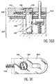
Avantageusement, dans chaque ensemble, un joint est disposé entre deux éléments de cheminée correspondant respectivement à deux modules différents de façon à assurer l'étanchéité entre deux modules consécutifs, ces modules étant appelés modules intermédiaires.Advantageously, in each set, a joint is arranged between two chimney elements corresponding respectively to two different modules so as to seal between two modules consecutive, these modules being called modules intermediate.
Toutefois un ensemble dit "unitaire" peut être formé d'un seul module contenant une alvéole.However, a so-called "unitary" set can be formed of a single module containing a cell.
Avantageusement, les éléments de cheminée reçoivent, selon la nature du module auquel ils appartiennent, un joint à chaque extrémité dans le cas d'un module intermédiaire, un joint pour la face associée à un module intermédiaire et un connecteur pour la face susceptible d'être connectée à un autre ensemble dans le cas d'un module terminal, ou un connecteur à chaque extrémité dans le cas où un module est un ensemble unitaire.Advantageously, the chimney elements receive, depending on the nature of the module to which they belong, a seal at each end in the case an intermediate module, a seal for the face associated with an intermediate module and a connector for the face that can be connected to another together in the case of a terminal module, or a connector at each end in case a module is a unitary whole.
Dans une variante de réalisation les éléments de cheminée reçoivent un élément de filtration permettant le filtrage des particules qui pourraient être libérées lors de la connexion/déconnexion de modules. L'élément de filtration comprend une couronne centrale composée d'une couronne rigide sur laquelle est rapportée une membrane filtrante. Avantageusement le connecteur autobloquant comprend un clapet monté sur un ressort guidé par un flasque monté étanche grâce à un joint sur l'élément de cheminée correspondant, un joint à lèvre permettant d'assurer l'étanchéité entre éléments de cheminée, et des formes complémentaires.In an alternative embodiment the chimney elements receive a filtration element allowing the filtering of particles which could be released when logging in / out of modules. The filter element includes a crown central composed of a rigid crown on which a filter membrane is added. advantageously the self-locking connector includes a valve mounted on a spring guided by a flange mounted tight thanks to a joint on the corresponding chimney element, a lip seal for sealing between fireplace elements, and complementary shapes.
Dans une autre variante de réalisation, l'élément de filtration comprend une couronne en matière filtrante. Le connecteur autobloqueur comprend une membrane élastique en forme de tripode venant se loger dans un emplacement aménagé dans la partie inférieure d'un flasque muni sur sa face inférieure d'une portée conique.In another alternative embodiment, the filter element comprises a crown in filter material. The self-locking connector includes an elastic membrane in the shape of a tripod coming stay in a site fitted out in the bottom of a flange provided on its underside of a conical bearing.
Chaque ensemble est doté de moyens de verrouillage manuels ou automatiques à un autre ensemble unitaire ou non qui lui serait associé permettant l'association et la dissociation d'au moins deux ensembles unitaires ou non.Each set has means of manual or automatic locking to another unitary unit or not associated with it allowing the association and dissociation of at least two unitary sets or not.
On assemble un ensemble En+1 sur un ensemble En par action sur un levier du mécanisme d'assemblage appartenant à l'ensemble En afin de ne pas dépositionner En+1 par rapport à En, En étant déjà bloqué par rapport à En-1.We assemble an En + 1 set on a together In by action on a mechanism lever assembly belonging to the En set so as not to depose En + 1 with respect to En, Being already blocked compared to En-1.
Ce procédé d'assemblage est applicable pour l'assemblage de modules. Pour réaliser des ensembles à partir de modules unitaires, après avoir réaliser un empilement de modules, on retire tous les leviers de manoeuvre des modules intermédiaires, on ne conserve que celui du module terminal haut, qui sert à l'amarrage d'un autre ensemble.This assembly process is applicable for assembly of modules. To make sets with starting from unit modules, after having carried out a stack of modules, we remove all the levers operation of the intermediate modules, than that of the top terminal module, which is used to mooring another set.
Dans un exemple de réalisation de l'invention particulièrement avantageux les objets plats sont des plaques de semi-conducteur.In an example of realization of the invention particularly advantageous the objects dishes are semiconductor plates.
L'invention concerne également un procédé de transfert d'un objet plat d'une alvéole du dispositif décrit ci-dessus, dans une machine de traitement, caractérisé en ce que ledit dispositif est positionné de telle sorte que chaque alvéole puisse être mise en communication avec ladite machine afin qu'un robot, dont est dotée ladite machine, puisse effectuer un transfert dudit objet dans un sens ou dans l'autre tout en préservant l'environnement de pureté et de propreté entourant l'objet durant le transfert.The invention also relates to a method of transfer of a flat object from a cell of the device described above, in a treatment, characterized in that said device is positioned so that each cell can be put in communication with said machine so that a robot, with which said machine is equipped, can transfer said object in one direction or in each other while preserving the environment of purity and cleanliness surrounding the object during transfer.
Avantageusement pour réaliser une connexion on a les étapes suivantes :
- positionnement du dispositif de l'invention sur le plateau de la machine ;
- positionnement d'au moins une alvéole en face du mors mobile de la bride ;
- raccordement étanche entre au moins une alvéole du dispositif de l'invention avec la machine par déplacement du mors mobile de la bride grâce à un mécanisme de translation solidaire de la bride ;
- purge du volume mort entre la porte de l'alvéole et la porte du mors mobile ;
- mise en contact de la porte de l'alvéole sur la porte du mors mobile, en actionnant les baïonnettes associées à l'alvéole par un mécanisme solidaire de la partie fixe de la bride, l'action sur les baïonnettes permettant aussi de solidariser les deux portes ;
- ouverture simultanée des deux portes ainsi solidarisées pour emprisonner les contaminations à l'interface, cet escamotage, réalisé par un mécanisme solidaire du mors mobile des deux portes à l'intérieur du mors mobile, libérant un espace suffisant au passage du doigt du robot interne de la machine pour prendre ou déposer un objet plat dans l'alvéole (par exemple une plaque de silicium) ;
- transfert de l'objet plat par le robot ;
- isolation sur le plan contamination de l'alvéole et de la machine : on réalise un flux de gaz approprié dans le mors mobile afin d'isoler sur le plan contamination l'intérieur de l'enveloppe par rapport à la machine pour éviter la contamination des alvéoles au moment du transfert de l'objet plat ; toutefois, dans le cas des équipements "vide", il n'y a pas d'injection de gaz mais liaison au circuit de vide ;
- fermeture simultanée par le mécanisme de bride des deux portes maintenues en contact ; une fois la position atteinte, la porte du mors mobile fermant de façon étanche la machine, alors que la porte de l'alvéole ne ferme pas l'alvéole de façon étanche ;
- reconditionnement de l'atmosphère de l'alvéole avant fermeture : dans cette position on reconditionne la pureté dans l'enveloppe en injectant un gaz approprié ; toutefois on ne réalise pas cette opération pour les équipements "vide" ;
- désolidarisation des deux portes par action du mécanisme sur la bride, sur les baïonnettes de la porte de l'alvéole et recul de la porte de l'alvéole jusqu'à fermer de façon étanche l'alvéole ;
- retrait du mors mobile par action du mécanisme de transfert solidaire de la bride ;
- possibilité, alors, d'indexer pour ouvrir une autre alvéole ou bien de retirer le dispositif de l'invention de la machine.
- positioning of the device of the invention on the machine table;
- positioning of at least one cell opposite the movable jaw of the flange;
- sealed connection between at least one cell of the device of the invention with the machine by displacement of the movable jaw of the flange by means of a translation mechanism integral with the flange;
- purging the dead volume between the cell door and the movable jaw door;
- bringing the cell door into contact with the mobile jaw door, by actuating the bayonets associated with the cell by a mechanism secured to the fixed part of the flange, the action on the bayonets also making it possible to secure the two doors ;
- simultaneous opening of the two doors thus secured to trap contamination at the interface, this retraction, produced by a mechanism integral with the movable jaw of the two doors inside the movable jaw, freeing up sufficient space for the passage of the finger of the internal robot the machine for picking up or placing a flat object in the cell (for example a silicon plate);
- transfer of the flat object by the robot;
- isolation in terms of contamination of the cell and the machine: an appropriate gas flow is made in the movable jaw in order to isolate the inside of the envelope from the contamination in relation to the machine to avoid contamination of the alveoli at the time of transfer of the flat object; however, in the case of "vacuum" equipment, there is no gas injection but connection to the vacuum circuit;
- simultaneous closing by the flange mechanism of the two doors kept in contact; once the position reached, the door of the movable jaw sealingly closing the machine, while the door of the cell does not close the cell sealingly;
- reconditioning of the atmosphere of the cell before closing: in this position, the purity is reconditioned in the envelope by injecting an appropriate gas; however, this operation is not carried out for "empty"equipment;
- separation of the two doors by action of the mechanism on the flange, on the bayonets of the cell door and recoil of the cell door until the cell is sealed;
- removal of the movable jaw by action of the transfer mechanism integral with the flange;
- possibility, then, to index to open another cell or to remove the device of the invention from the machine.
Avantageusement on utilise au moins une bride comportant une partie mobile, fermée par une porte, qui avance vers au moins une alvéole à ouvrir afin de réaliser une liaison étanche entre la machine et l'alvéole. Un mors mobile est raccordé à la partie fixe de la bride par un soufflet pour assurer la translation et garantir l'étanchéité avec la machine. Dans le cas du raccordement des équipements "vide" ce soufflet est métallique. La bride est dotée de moyens permettant d'ouvrir la porte de l'alvéole et la porte fermant la bride afin de réaliser un tunnel de communication étanche dans lequel le robot de la machine peut réaliser le transfert de l'objet.Advantageously, at least one flange comprising a movable part, closed by a door, which advances towards at least one cell to be opened in order to create a tight connection between the machine and the socket. A movable jaw is connected to the fixed part of the flange by a bellows to ensure translation and guarantee sealing with the machine. In the case of equipment connection "empty" this bellows is metallic. The flange is provided with means for opening the door the cell and the door closing the flange in order to build a waterproof communication tunnel in which the machine robot can transfer the object.
La porte, qui est indépendante de l'alvéole correspondante et amovible, est complètement désolidarisée de celle-ci au moment de l'ouverture pour libérer complètement le passage du robot.The door, which is independent of the cell matching and removable, is completely separated from it at the time of opening for completely free the passage of the robot.
Dans un exemple de réalisation un mécanisme, qui permet de verrouiller la porte pour fermer l'alvéole, est commandé et animé par un mécanisme complémentaire solidaire de la porte de la bride d'ouverture. L'association de ces deux mécanismes déverrouille la porte fermant l'alvéole et libère celle-ci, ces deux mécanismes étant alors solidarisés.In an exemplary embodiment a mechanism, which allows the door to be locked to close the cell, is controlled and driven by a complementary mechanism integral with the door of the opening flange. The combination of these two mechanisms unlocks the door closing the cell and releases the latter, these two mechanisms then being joined.
Grâce à plusieurs mécanismes dont est munie la bride, on réalise l'avance ou le recul du mors mobile, on vient engager deux butées solidaires d'un mécanisme d'oreillettes, de part et d'autre de l'alvéole pour que le mors mobile puisse venir exercer une pression sur l'alvéole pour assurer l'étanchéité sans dépositionner le dispositif de l'invention ; un mécanisme actionne les baïonnettes pour assurer le transfert de la porte de l'alvéole sur la porte du mors mobile et libérer cette porte pour permettre son escamotage dans le mors mobile ; grâce à un mécanisme dont est doté le mors mobile on peut réaliser l'escamotage des deux portes.Thanks to several mechanisms which are provided the flange, the jaw is moved forward or backward mobile, we just engage two stops integral with a headset mechanism on either side of the socket so that the movable jaw can come to exert pressure on the cell to seal without depositing the device of the invention; a mechanism operates the bayonets to ensure the transfer from the cell door to the jaw door mobile and free this door to allow its retraction in the movable jaw; through a mechanism with the movable jaw we can realize the retraction of the two doors.
Avantageusement on contrôle, avant l'accostage, la position de l'alvéole à ouvrir. Le contrôle de la position du doigt du robot ou de l'objet est réalisé au moment de la prise ou de la dépose d'un objet de façon à réaliser cette opération sans frottement. L'identification de l'objet peut être lue à la volée par un dispositif électro-optique.Advantageously, we check before docking, the position of the cell to open. The control of the position of the robot finger or of the object is carried out when taking or removing a object so as to perform this operation without friction. The identification of the object can be read at the fly by an electro-optical device.
Avantageusement deux butées solidaires d'un mécanisme d'oreillettes permettent de maintenir un positionnement précis du dispositif de l'invention alors que le mors mobile qui est muni d'un joint, exerce une pression sur son joint afin d'assurer l'étanchéité avec l'alvéole considérée.Advantageously two stops integral with a ear cup mechanism to maintain a precise positioning of the device of the invention while the movable jaw which is provided with a seal, exerts pressure on its joint to ensure sealing with the cell in question.
Avantageusement la bride est munie de moyens qui permettent de purger les volumes morts et de restaurer l'environnement pur de l'alvéole avant de la fermer. Elle est aussi muni de moyens permettant de contrôler la position dudit dispositif, de contrôler la position relative de l'objet au moment de son transfert, et de lire son identifiant, pendant son transfert.Advantageously, the flange is provided with means to purge dead volumes and restore the pure environment of the cell before the to close. It is also provided with means allowing control the position of said device, control the relative position of the object at the time of its transfer, and read its identifier, during its transfer.
Avantageusement lorsque la machine met en oeuvre un procédé réalisé sous vide et qu'elle est nécessairement munie d'un sas de transfert, le dispositif de l'invention appelé aussi cassette, peut 5 être installé dans le sas. Dans ce cas on réalise simultanément le vide dans les différentes alvéoles du dispositif grâce aux cheminées et dans le sas de transfert de celui-ci.Advantageously when the machine puts in works a process carried out under vacuum and that it is necessarily equipped with a transfer airlock, the device of the invention also called cassette, can 5 be installed in the airlock. In this case we realize simultaneously the vacuum in the different cells of the device thanks to the chimneys and in the airlock transfer of it.
Ensuite l'interfaçage se fait comme décrit précédemment pour le transfert d'objets vers les machines dont les procédés sont réalisés dans le vide sans rupture de la chaíne de propreté et/ou de pureté entourant les objets et surtout sans nécessité d'opérations supplémentaires pour sortir les objets des alvéoles et les réintroduire dans le sas de la machine. Cette descente en vide, simultanément dans chaque alvéole, est assurée et régulée par un moyen exploitant les informations des capteurs de pression installés dans la cassette et dans le sas. Ce moyen comporte un dispositif de pompage. Les mêmes moyens permettent également remonter à la pression atmosphérique par contrôle de l'injection d'azote en simultanéité dans le sas et dans les alvéoles.Then the interfacing is done as described previously for the transfer of objects to machines whose processes are carried out in a vacuum without breaking the chain of cleanliness and / or purity surrounding objects and especially unnecessary additional operations to remove objects from cells and reintroduce them into the machine lock. This descent into vacuum, simultaneously in each cell, is ensured and regulated by an operating means information from installed pressure sensors in the cassette and in the airlock. This plea involves a pumping device. The same means allow also go back to atmospheric pressure by simultaneous nitrogen injection control in the airlock and in the alveoli.
L'invention permet de rendre les plaques de semi-conducteur accessibles par le robot interne des équipements, sans nécessiter de robot supplémentaire.The invention makes it possible to make the plates of semiconductor accessible by the internal robot equipment, without the need for an additional robot.
Les principaux avantages de l'invention par rapport aux dispositifs de l'art antérieur sont explicités notamment sur le tableau I en fin de description.The main advantages of the invention by compared to the prior art devices are explained in particular in Table I at the end of description.
- Les figures 1 à 3 illustrent différents dispositifs de l'art antérieur, les figures 1A, 2A et 3A correspondant aux zones de travail et les figures 1B, 2B et 3B correspondant aux zones de transfert et de stockage ; Figures 1 to 3 illustrate different devices of the prior art, FIGS. 1A, 2A and 3A corresponding to the work areas and the figures 1B, 2B and 3B corresponding to the transfer and storage;
- les figures 4 à 8 illustrent d'autres dispositif de l'art antérieur ;Figures 4 to 8 illustrate other prior art device;
- les figures 9 et 12 illustrent une première réalisation du dispositif de l'invention ;Figures 9 and 12 illustrate a first embodiment of the device of the invention;
- les figures 13 à 20 illustrent une seconde réalisation du dispositif de l'invention à base de modules ; les figures 14 et 16 à 20 illustrant différentes caractéristiques d'un module de base du dispositif de l'invention ;Figures 13 to 20 illustrate a second embodiment of the device of the invention based modules; Figures 14 and 16 to 20 illustrating different characteristics of a basic module of the device of the invention;
- la figure 21 illustre un élément de cheminée muni de deux connecteurs permettant la liaison avec des éléments voisins ;Figure 21 illustrates an element of chimney provided with two connectors allowing the connection with neighboring elements;
- le figure 22 illustre le procédé selon l'invention de transfert d'objets plats entre le dispositif de l'invention et une machine de traitement ;Figure 22 illustrates the process according to the invention of transfer of flat objects between the device of the invention and a machine for treatment ;
- la figure 23 illustre un système de mise sous vide du dispositif selon l'invention ;Figure 23 illustrates a stakeout system under vacuum of the device according to the invention;
- les figures 24 à 38 illustrent différentes variantes de réalisation du dispositif de l'invention.Figures 24 to 38 illustrate different variants of the device the invention.
La présente invention concerne un
dispositif de transport d'objets plats 10, par exemple
des plaques de semi-conducteur, confinés dans une
atmosphère déterminée. Ce peut être par exemple, comme
représenté sur la figure 9, un ensemble 30, en
plastique ou en métal, muni d'une ou de plusieurs
alvéoles plates 31, ici neuf, de faible épaisseur,
débouchant sur une face latérale 32 dudit ensemble,
disposées en parallèle, réunies entre elles d'un point
de vue aéraulique. Chaque alvéole est apte à recevoir
un objet plat 10 et à être fermée par une porte 33
indépendante s'étendant sur toute la longueur de cette
face latérale. Chaque porte 33 est séparable de
l'ensemble. La fermeture et l'ouverture de chaque porte
33 sont assurées par un dispositif de verrouillage et
de déverrouillage. les alvéoles 31 sont séparées entre
elles d'un pas constant.The present invention relates to a
device for transporting
Chaque ensemble 30 comporte un élément de
cheminée d'amenée de gaz 35 et un élément de cheminée
de retour de gaz 36. Ces deux éléments de cheminée
disposés sur la face de l'ensemble 30 opposée aux
ouvertures, associés à une poignée 55, permettent la
préhension de celui-ci. Cette poignée 51 de
manipulation du dispositif de l'invention peut être
assemblée comme un autre ensemble 30 sur la face
supérieure de ce dispositif.Each set 30 includes an element of
Les éléments de cheminée 35 et 36 sont
terminés par un connecteur auto-obturant 38.The
Chaque ensemble 30 comprend des moyens de positionnement des différents ensembles entre eux 28, des moyens d'assemblage 51 à un autre ensemble qui lui serait associé, des moyens d'identification, des moyens de sustentation d'objet dans chaque alvéole et de répartition des gaz, des moyens capteur de contrôle et des moyens de transfert d'information vers d'autres ensembles qui lui seraient associés.Each set 30 includes means for positioning of the different sets between them 28, assembly means 51 to another assembly which would be associated, means of identification, means object lift in each socket and gas distribution, control sensor means and means of transferring information to others sets associated with it.
Sur la figure 9 est également représenté un
plateau 80 sur lequel peut être disposé le dispositif
de l'invention. La figure 10 illustre la face
inférieure du dispositif de l'invention munie de picots
51 et de plots de positionnement 60. La figure 11
illustre un plateau 61 compatible pour la prise par un
robot avec le même mode d'assemblage que la poignée 55.Figure 9 also shows a
Comme représenté sur la figure 12 le
dispositif de l'invention appelé cassette peut être
constitué d'un ou de plusieurs ensembles 30 tels que
définis ci-dessus, associés entre eux, chaque ensemble
comportant une ou plusieurs alvéoles.As shown in Figure 12 the
device of the invention called cassette can be
consisting of one or
Dans une variante de réalisation illustrée
sur la figure 13, le dispositif de l'invention est
formé d'un ou de plusieurs ensembles 39 ; mais chaque
ensemble 39 est lui-même constitué d'un ou plusieurs
modules 40 associés mécaniquement entre eux de manière
indissociable, telle qu'à chaque alvéole correspond à
présent un module indépendant. Quelle que soit la
constitution de la cassette, ces différents ensembles
constitutifs sont dissociables lors du nettoyage et
peuvent être associés à la demande pour réaliser un
autre lot de traitement d'objets plats, cette nouvelle
association étant figée pour tout un cycle.In an illustrated embodiment
in FIG. 13, the device of the invention is
formed by one or
Sur la figure 13 est représenté, à titre
d'exemple, un ensemble 39 formé d'un seul module 40 et
deux ensembles 39 formés de quatre modules 40.In Figure 13 is shown, as
for example, an
Le module unitaire 40 peut être utilisé
pour recevoir un objet 10, par exemple une plaque de
semi-conducteur, servant de référence.The
Les ensembles constitués d'un seul bloc comme illustré sur la figure 9, ou d'un ou plusieurs modules comme illustré sur la figure 13, sont associables et dissociables entre eux pour obtenir un dispositif de transport d'utilisation flexible, c'est-à-dire adapté au besoin de l'opérateur, le pas entre les différentes alvéoles, même au raccordement de deux ensembles, restant le même.Self-contained sets as shown in Figure 9, or one or more modules as illustrated in figure 13, are associable and dissociable between them to obtain a flexible use transport device, i.e. adapted to the operator's needs, the step between the different cells, even at the connection of two together, staying the same.
Comme représenté sur la figure 14, un
module de base 40 est constitué une enceinte 41 de part
et d'autre de laquelle sont disposés deux coques 42 et
43 assemblées entre elles, protégeant l'enceinte 41.As shown in Figure 14, a
Cette enceinte 41 comprend :
- des plots de positionnement 60 illustrés notamment sur la figure 17 pour positionner les enceintes les unes par rapport aux autres lors de l'assemblage des différents modules ;
un dispositif d'assemblage 45 ;- des éléments de cheminée 46
et 47 ; - deux dispositifs 48 permettant la sustentation des objets plats et de répartition de gaz à l'intérieur de l'enceinte ;
une porte 49 pour fermer de façon étanche l'enceinte 41 et les baïonnettes de manoeuvre 50 pour ouvrir et fermer et maintenir la porte fermée, pour faire avancer la porte dans la bride de raccordement et pour la libérer afin de permettre l'escamotage de la porte dans la bride.
- positioning
pads 60 illustrated in particular in Figure 17 to position the speakers relative to each other during the assembly of the different modules; - an
assembly device 45; -
chimney elements - two
devices 48 allowing the levitation of flat objects and distribution of gas inside the enclosure; - a
door 49 for sealingly closing theenclosure 41 and the operating bayonets 50 for opening and closing and keeping the door closed, for advancing the door in the connection flange and for releasing it in order to allow the retraction of the door in the flange.
L'enceinte 41 est réalisée idéalement dans
un matériau qui protège les objets plats 10 des
contaminations moléculaires et chimiques, qui ne
désorbe pas ni n'absorbe de contamination moléculaire,
suffisamment conducteur pour éviter l'accumulation des
charges électrostatiques et avantageusement léger. Dans
la pratique, on peut utiliser des matériaux pris dans
la famille des polycarbonates légèrement chargés de
fibres conductrices.The
Pour l'application micro-électronique, afin
de garantir le degré de pureté requis, on peut procéder
à un dépôt à l'intérieur de l'enceinte 41 d'une couche
à base de silice rendue légèrement conductrice pour
évacuer les charges électrostatiques. Ces charges sont
écoulées à la masse par le système de sustentation,
lui-même connecté aux coques de protection de
l'enceinte comme représenté sur la figure 15.
L'assemblage de ces deux coques réalise aussi un écran
électrostatique et électromagnétique pour protéger
l'objet situé à l'intérieur de l'enceinte de ce type de
perturbation.For the microelectronic application, so
to guarantee the required degree of purity, we can proceed
to a deposit inside the
Les coques 42 et 43 sont, par exemple,
réalisées en plastique chargé fortement de fibres
conductrices pour les rendre très conductrices.The
Les coques 42 et 43 comportent des trous
permettant le passage des plots de positionnement. Les
deux coques qui entourent l'enceinte sont assemblées
entre elles, par exemple avec des vis 62, et ont pour
rôle de protéger l'enceinte. Des logements sont prévus
dans ces coques pour recevoir le mécanisme de
baïonnettes 50, le verrou d'assemblage 52, et
avantageusement une étiquette d'identification du
module et/ou une étiquette radiofréquence
réinscriptible, capable de mémoriser par exemple,
l'identification de l'objet 10 et/ou les informations
sur l'état d'avancement du procédé appliqué à l'objet
contenu dans l'enceinte.
Le dispositif d'assemblage 45 permet
d'assembler des modules entre eux et permet d'effectuer
la connexion électrique de masse pour permettre
l'écoulement des charges électrostatiques accumulées
sur les objets plats et dans les enceintes. Ce
dispositif d'assemblage comporte des emplacements dans
lesquels seront placés des capteurs.The
Les éléments de cheminée reçoivent, selon
la nature du module auxquels il appartiennent, un joint
44 à chaque extrémité dans le cas d'un module
intermédiaire, un joint 44 à une extrémité et un
connecteur 38 à l'autre dans le cas d'un module
terminal, ou un connecteur 38 à chaque extrémité dans
le cas où un module est un ensemble unitaire.The chimney elements receive, according to
the nature of the module to which it belongs, a joint
44 at each end in the case of a module
intermediate, a
Les dispositifs 48 pour la sustentation des
objets plats et de répartition de gaz à l'intérieur de
l'enceinte sont rapportés dans l'enceinte. The
Les baïonnettes de manoeuvre permettent évidemment les opérations inverses à celles décrites.The operating bayonets allow obviously the reverse operations to those described.
Avantageusement l'enceinte comprend
différents capteurs, par exemple un capteur de pression
ou de présence d'oxygène, situés dans des logements
prévus à cet effet par exemple le logement 64.Advantageously, the enclosure includes
different sensors, for example a pressure sensor
or presence of oxygen, located in housing
provided for this purpose, for
La porte 49 réalise une fermeture étanche
du module 40 par la pression d'un joint, par exemplaire
plan ou « genouillère », solidaire de la porte sur une
forme adaptée, par exemple de type « couteau », du
module. La pression est assurée par les baïonnettes de
manoeuvre 50 dotées d'un ressort de rappel.
Comme représenté sur les figures 14, 17 et
18, le dispositif d'assemblage 45 comprend un piton 51
rapporté sur une excroissance réalisée sur le enceinte
41, cette excroissance possédant deux rainures dans
lesquelles peut se déplacer le verrou 52 pour réaliser
l'assemblage des enceintes de deux modules successifs
Mn+1 et Mn. Le verrouillage du module Mn+1 est réalisé
par action sur le module Mn, Mn étant déjà bloqué.As shown in FIGS. 14, 17 and 18, the
Sur la figure 18 le module supérieur est un
module terminal haut Mn d'un ensemble et comporte un
levier 63 qui lui permet de déverrouiller un ensemble
Mn+1 qui lui serait superposé. Les modules
intermédiaires ou bas Mn-1 ..., constituant un
ensemble, sont non déverrouillables et ne comportent
pas un tel levier parce que celui-ci a été enlevé pour
qu'ils puissent constituer un tel ensemble.In FIG. 18, the upper module is a top terminal module M n of an assembly and includes a
Comme représenté sur la figure 14 la porte
49 est munie d'un ressort 54 de blocage de l'objet plat
10.As shown in figure 14 the
Un dispositif 48 permettant la sustentation
de l'objet plat 10, illustré sur les figures 14, 16, 19
et 20 a la forme d'un tube 55 réalisé, par exemple,
par une tige pleine dans laquelle est percé un orifice
qui va en se rétrécissant, cet orifice étant percé de
trous 56. Le blocage de l'objet 10 est réalisé par deux
butées maintenant l'objet en position, réalisées aux
premières extrémités des deux tubes 55 et par la porte
et son ressort de blocage.A
Le bouchon 57 et le ressort 58 permettent
de maintenir le tube 55 dans son logement. Un logement
59 est prévu dans le boítier 41 pour blocage de ce tube
55.The
Le matériau de ce tube est par exemple du
plastique de type PEEK conducteur permettant de
maintenir le potentiel de l'objet à la masse et de
conduire les charges électrostatiques vers les coques
conductrices 42 et 43, elles-mêmes maintenues à la
masse. Le bouchon 57 et le ressort 58 assurent le
contact électrique.The material of this tube is for example
conductive PEEK type plastic allowing
maintain the object's potential to ground and
conduct electrostatic charges towards the hulls
conductive 42 and 43, themselves maintained at the
mass. The
Ce dispositif 48 est également utilisé pour
répartir le gaz dans l'enceinte.This
Dans un mode avantageux de l'invention, les alvéoles peuvent être réalisées dans un plastique résistant à des températures d'environ 120°C pouvant alors être utilisées pour réaliser un procédé de traitement des objets. Par exemple, elles peuvent ainsi être utilisées pour stabiliser un procédé d'implantation ionique : en contrôlant la température de l'azote injecté, on peut contrôler parfaitement le refroidissement des objets.In an advantageous embodiment of the invention, the alveoli can be made of plastic resistant to temperatures of around 120 ° C then be used to carry out a process of treatment of objects. For example, they can be used to stabilize a process ion implantation: by controlling the temperature injected nitrogen, we can perfectly control the cooling objects.
Avantageusement l'enceinte 41 peut être
réalisée dans un matériau compatible avec les
spécifications de l'objet confiné.Advantageously, the
Pour les plaques de silicium, cette enceinte doit être en plastique pour des raisons de légèreté. Pour des applications où il n'est pas nécessaire de voir les plaques cette enceinte peut être réalisée dans des matériaux de type polycarbonate chargés de fibres conductrices pour écouler les charges électrostatiques.For silicon wafers, this enclosure must be plastic for reasons of lightness. For applications where it is not necessary to see the plates this enclosure can be made of polycarbonate materials loaded with conductive fibers to discharge the charges electrostatic.
Pour des applications où il est nécessaire de conserver la transparence et où les conditions d'environnement sont très sévères en terme de dégazage, on utilise du polycarbonate revêtu à l'intérieur d'une couche barrière de moins de 1 micromètre de silice convenablement dopé en silicium pour la rendre légèrement conductrice, sans perte de la transparence.For applications where it is necessary to maintain transparency and where the conditions environment are very severe in terms of degassing, polycarbonate coated inside a barrier layer of less than 1 micrometer of silica suitably doped with silicon to make it slightly conductive, without loss of transparency.
Les deux coques 42, 43 constituant le
boítier de protection et de maintien de l'enceinte
peuvent être réalisées en plastique conducteur.The two
Les charges électrostatiques créées sur les
faces internes de l'enceinte et celles véhiculées par
l'objet vont être écoulées vers le boítier conducteur
par le mécanisme de sustentation (48), lui-même
conducteur grâce au contact réalisé par le ressort (57)
et le bouchon (58). Le verrou 52 en connexion avec la
coque par un ressort va écouler les charges sur le
verrou du module sous-jacent via le piton conducteur
51, créant ainsi une chaíne de "masse" jusqu'au plateau
conducteur sur lequel est positionné le mécanisme de
l'invention, plateau raccordé à la masse, comme
représenté sur la figure 15.The electrostatic charges created on the
internal faces of the enclosure and those conveyed by
the object will be passed to the conductive housing
by the lift mechanism (48), itself
conductor thanks to the contact made by the spring (57)
and the plug (58). The
Un connecteur auto-obturant 38, comme
illustré sur la figure 21, permet d'assurer d'une part
l'étanchéité des volumes intérieurs des enceintes pour
les extrémités non connectées, et d'autre part la
continuité de la distribution de gaz pour les parties
connectées.A self-sealing
Un tel connecteur 38 comprend un corps 65,
muni de deux canaux 66 permettant le passage du gaz, à
l'intérieur duquel un système poussoir 67, actionné par
un ressort 68, est apte à repousser une bille 69
disposée dans un siège muni d'un chanfrein 70, une
membrane 71 de protection contre la contamination du
ressort étant disposée entre le système poussoir 67 et
la bille 69. Un joint torique 72 est disposé sur la
périphérie extérieure supérieure de ce corps.Such a
Lorsque deux connecteurs de ce type sont
reliés l'un à l'autre, l'étanchéité est réalisée grâce
aux joints, et l'appui des deux billes l'une sur
l'autre permet la mise en communication des canaux de
passage de gaz entre eux : sur la figure 21 le
connecteur auto-obturant 38 situé en bas est représenté
en connexion avec un même connecteur disposé sur un
plateau 80 représenté en tiretés.When two connectors of this type are
connected to each other, sealing is achieved by
at the joints, and the support of the two balls, one on
the other allows the communication channels
gas passage between them: in figure 21 the
self-sealing
Dans une variante de réalisation, illustrée
sur la figure 24, le module de base 40 est réalisé en
une seule pièce transparente, pour pouvoir identifier
et observer l'objet plat 10 situé à l'intérieur. Cette
pièce peut être totalement transparente, ou au minimum
transparente dans les zones 81 en regard de l'objet
plat 10. Sur la figure 24 est représentée une telle
zone minimum 81.In an alternative embodiment, illustrated
in FIG. 24, the
On peut ainsi observer et identifier
l'objet plat, par exemple la plaque de silicium 10 à
l'intérieur du module 40 sans avoir à la sortir, c'est-à-dire
en la maintenant dans son environnement ultrapur
et/ou ultra-propre.We can thus observe and identify
the flat object, for example the
Comme illustré sur la figure 25 un
nervurage spécial 82 de type « mâle-femelle » peut
permettre d'accroítre la rigidité du module 40, aussi
bien au niveau du « nez » du module, qu'au niveau des
cheminées d'admission de gaz.As illustrated in Figure 25 a
A titre d'exemple on peut réaliser la partie non transparente très rigide en polycarbonate chargé fibre de verre ou aiguille de silice, et la partie transparente en polycarbonate. On peut, pour ce faire, utiliser des plaques transparentes rapportées sur un cadre par soudage ou à force avec un joint, ou un moulage bi-matière.By way of example, the very rigid non-transparent polycarbonate part fiberglass or silica needle, and the transparent polycarbonate part. We can, for this do, use attached transparent plates on a frame by welding or by force with a joint, or a bi-material molding.
Dans une variante de réalisation, comme
illustré sur les figures 26 à 29, la forme des
dispositifs 48 pour la sustentation des objets plats 10
et le mode de diffusion de gaz sont modifiés ; la
figure 27 illustrant une coupe a-a de la figure 26 et
la figure 29A illustrant une coupe b-b de la figure 28.In an alternative embodiment, as
illustrated in FIGS. 26 to 29, the shape of the
Comme illustré sur la figure 27 chaque
dispositif 48, situé de part et d'autre du module 40, a
une coupe se rapprochant de la forme d'un « T » qui
permet de réaliser un flux de gaz horizontal et
transverse à l'objet plat. En effet la partie interne
du module 40 et chaque dispositif 48 réalisent un
« plénum » permettant de répartir le gaz dans le module
par un dispositif 48 d'injection et d'évacuer le gaz
par un dispositif 48 d'échappement.As illustrated in Figure 27 each
Chaque dispositif 48 reste conducteur pour
écouler les charges et maintenir l'objet plat 10 à un
potentiel électrique voisin de la masse.Each
La fonction blocage de l'objet plat 10 est
assurée par un système de positionnement rigide 86 en
forme de « coin » solidaire de la porte 49. L'effet
« blocage », positionnement de l'objet plat 10, porte
fermée ou porte ouverte, est assuré par deux butées
ressort 85 et deux éléments 87 en forme de fourchette
solidaires du système de sustentation 48, comme
illustré sur la figure 29B, empêchant l'objet plat 10
de bouger dans le module 40.The blocking function of the
Lorsque la porte 49 est ouverte, les butées
ressort 85 repoussent légèrement l'objet plat 10 vers
l'avant pour le libérer des éléments 87 permettant,
ainsi, à l'objet plat 10 d'être pris par un robot de
préhension.When
Dans une variante de réalisation le système
d'association des modules 40, comme illustré sur la
figure 24, est obtenu comme illustré sur les figures 30
et 31 en utilisant des formes complémentaires 90 sous
forme d'oreillettes, la figure 30 illustrant une coupe
c-c de la figure 31. Chaque module 40 comporte, de
chaque côté, une oreillette supérieure 92 et deux
oreillettes inférieures 91. Ces oreillettes 91 et 92,
dont le rôle pourrait être inversé, sont réalisées sur
chacun des modules 40 pour permettre leur empilage et
pour amener en correspondance deux oreillettes
inférieures 91 d'un module N avec l'oreillette
supérieure 92 complémentaire d'un module N-1.In an alternative embodiment the system
of association of the
Un mécanisme logé dans les oreillettes
inférieures 91 permet d'une part de venir verrouiller
les modules 40 entre eux et d'autre part, de venir
plaquer les modules 40 les uns sur les autres pour
garantir le positionnement relatif et la pression
nécessaire pour obtenir l'étanchéité de l'empilage des
différents éléments de cheminée.A mechanism housed in the ear cups
lower 91 allows on the one hand to come and lock
La figure 32 illustre les mécanismes logés
dans les deux oreillettes inférieures 91 d'un module 40
de rang N et leur mode de fonctionnement.Figure 32 illustrates the mechanisms housed
in the two
Deux ergots 93 présentant un pan en biseau
pénètrent dans l'oreillette supérieure 92 du module 40
de rang N-1. Cette oreillette supérieure est dotée de
deux coins 97 qui font réaction aux biseaux des ergots
93 et transforment la pression exercée sur les ergots
93 par les deux ressorts 98 en une force tendant à
bloquer le module 40(N) sur le module 40(N-1).Two
Des doigts de manoeuvre 94 solidaires des
ergots 93 se déplaçant dans une lumière 95 réalisée
dans les oreillettes inférieures 91 permettent de
manoeuvrer les ergots afin de pouvoir désolidariser le
module supérieur N du module inférieur N-1.Operating
Les oreillettes 91 et 92 peuvent être soit
rapportées sur le module 40, soit faire partie de ce
module.
Dans une variante de réalisation illustrée
sur les figures 33 et 34, la porte 49 du module 40 est
composée de trois parties, un joint 100, un corps 101
sur lequel le joint est monté et un dispositif de
verrouillage 102 pour lier la porte avec le module 40.
Le joint 100 vient en butée sur les dispositifs de
sustentation 48 des objets plats 10 situés de part et
d'autre du module 40. La pression sur le joint 100 est
assurée par une pression sur le corps de la porte 49 au
moment de la fermeture de celle-ci, pression qui est
maintenue grâce à deux gâchettes 103, appartenant au
mécanisme de verrouillage 102, qui viennent se loger
dans deux logements 104 aménagés de part et d'autre du
« nez » du module 40.In an illustrated embodiment
in Figures 33 and 34, the
La pression sur le joint 100 en forme de
« genouillère » (voir figure 33) a pour effet de faire
grossir ce dernier sur tout son périmètre, répartissant
une force suffisante sur celui-ci pour assurer une
excellente étanchéité.The pressure on the
Différents matériaux peuvent être utilisés pour réaliser ce joint 100, par exemple le vitton, le kalrez, le chemraz.Different materials can be used to make this joint 100, for example the vitton, the kalrez, the chemraz.
Le joint 100 est armé par une armature 105
dont la rigidité est calculée pour répartir
convenablement la pression du joint 100 sur tout le
périmètre du « nez » du module 40.The
Un logement en forme de coin 106 aménagé
dans le joint 100 permet de bloquer l'objet plat 10
dans le module. Ce logement 106 joue le même rôle que
le « coin » 86, décrit précédemment, solidaire de la
porte 49.A 106-shaped corner accommodation
in the joint 100 allows to block the
Des formes particulières 111 et 112 sont
réalisées dans le nez du module 40 pour permettre d'une
part (forme 112) de réaliser une étanchéité vis-à-vis
de l'extérieur du module 40 grâce à un joint 120 de
forme oblongue, et d'autre part (forme 111) de recevoir
un corps de porte 101 doté d'une forme complémentaire à
(111) permettant de se prémunir des variations de forme
du nez du module 40.
Le dispositif de verrouillage 102 est
commandé et animé par un mécanisme complémentaire 107
solidaire de la contreporte d'une bride d'ouverture.The
L'association des mécanismes 102 et 107
permet de déverrouiller la porte 49 du module 40 pour
pouvoir libérer la porte du module. Dans la même action
les mécanismes 102 et 107 sont solidarisés pour
permettre de retirer la porte 49 du module 40.The combination of
Au moment de la fermeture du module 40 un
palpeur solidaire du mécanisme 107 permet de
reverrouiller la porte 49 sur son module 40 et de
libérer les mécanismes 102 et 107 pour pouvoir retirer
la bride.When
La figure 35A est une coupe du mécanisme
102 de verrouillage entre la porte 73 d'une alvéole et
le mécanisme 107 du système d'accouplement de
l'invention, et du mécanisme 107 complémentaire de
celui installé dans la porte. La position du mecanisme
représenté dans cette figure correspond à la position
lorsque les deux mécanismes 102 et 107 sont
désolidarisés.Figure 35A is a section of the
La figure 35B est une coupe du système de verrouillage lorsque la porte de l'alvéole est accouplée au mécanisme de la bride pour permettre l'escamotage de la porte de l'alvéole dans la bride. Figure 35B is a section through the locking when the cell door is coupled to the flange mechanism to allow the retraction of the cell door in the flange.
La figure 36 représente les deux positions
de la gâchette 103, en trait plein la position de
verrouillage de la porte 73 et en trait pointillé la
position de libération de la porte 73 qui correspond
aussi à la position de verrouillage sur la porte 74.Figure 36 shows the two positions
trigger 103, in solid line the position of
locking the
Comme illustré sur ces figures 35 et 36 un
exemple de mécanisme 102, permettant de verrouiller la
porte 73 pour fermer l'alvéole correspondante grâce à
deux gâchettes 103 qui viennent se loger dans deux
logements 104 correspondants, est commandé et animé par
un mécanisme complémentaire 107 solidaire de la porte
74 de la bride d'ouverture 70.As illustrated in these figures 35 and 36 a
example of
L'association des mécanismes 102 et 107
permet de déverrouiller la porte 73 fermant l'alvéole
pour pouvoir libérer celle-ci. Dans la même action les
mécanismes 102 et 107 sont solidarisés pour permettre
de retirer la porte 73.The combination of
Au moment de la fermeture de l'alvéole un
palpeur 114 solidaire du mécanisme 107 permet de
reverrouiller la porte 73 sur l'alvéole et de libérer
les mécanismes 102 et 107 pour pouvoir retirer la bride
70.At the time of closure of the cell a
Une gâchette 103, qui est montée dans le
corps de la porte, comporte deux ouvertures, une
première apte à laisser passer le palpeur 114 solidaire
du mécanisme 107, et une seconde dans laquelle vient se
positionner un bouchon 110, qui est maintenu en place
par un ressort 111, cette gâchette étant solidaire d'un
ressort de rappel 113.
Le mécanisme 107 comprend un palpeur 114
monté sur un ressort 118, et une pièce mobile en
rotation, ou percuteur, 112 comportant sur sa
périphérie une gorge 117 en forme de came et sur sa
surface supérieure un excentrique 115. Le palpeur 114
et le percuteur 112 sont montés en parallèle de manière
à ce qu'un ergot 116 solidaire de la base du palpeur
114 vienne se positionner dans la gorge, un appui sur
le palpeur 114 permettant une rotation du percuteur 112
d'un demi tour.The
La gâchette 103, montée dans le corps de la
porte 73, assure le verrouillage de la porte 73 pour
fermer l'alvéole et assure la liaison de la porte 73
avec la porte 74 de la bride pour permettre de retirer
la porte 73, et ainsi de pouvoir accéder à l'objet 10.
La gâchette 103 est maintenue en position
de verrouillage grâce au bouchon 110 maintenu en place
grâce au ressort 111.
Au moment de l'accostage la pièce 112 du
mécanisme 107 vient percuter le bouchon 110 qui en
reculant libère la gâchette 103 qui peut se retirer de
sa position de verrouillage grâce au ressort 113.At the time of docking,
Le palpeur 114 monté sur ressort 118
traverse le mécanisme 102 pour venir s'appuyer sur le
corps du module 40. En reculant ce palpeur 114 entraíne
en rotation le percuteur 112 grâce au système de came
116-117. Ce faisant, l'excentrique 115 pivote de 180°
permettant à la gâchette 103 de se mettre en position
déverrouillée et dans le même temps verrouille le
percuteur 112 avec la gâchette 103, liant ainsi les
mécanismes 102 et 107, et donc la porte 73 et la porte
74.The
La tête de la pièce 112 est dotée d'une
gorge excentrique 117 qui sous l'effet de la rotation
de 1/2 tour induite par le recul du palpeur 114 va
libérer la gâchette 103, qui tirée par le ressort 113
va se dégager du logement 104 déverrouillant ainsi la
porté 73 de l'alvéole. Se faisant, la gâchette 103 va
venir s'engager dans la gorge excentrique pour
verrouiller la porte 73 sur le mécanisme 107 permettant
ainsi l'escamotage de la porte. Cette situation est
illustrée figure 35B.The head of
Pour refermer une alvéole après un
transfert d'objet 10 et pouvoir ainsi libérer l'alvéole
de la bride pour accéder à d'autres alvéoles, le
mécanisme interne de la bride ramène l'ensemble porte
73-porte 74 représenté sur la figure 35B dans la
position d'accostage boíte-bride.To close a cell after a
Le palpeur 114 vient à nouveau prendre
appui sur le boítier de l'alvéole, être repoussé,
arrimant ainsi la pièce 112 d'un demi tour, dont la
gorge excentrique va repousser la gâchette 103 en
position de verrouillage de la porte 73. Dans cette
position, il est possible de désolidariser la porte 73
de la porte 74, la pièce 112 étant libérée de la
gâchette 103.The
En simultanéité du retrait du mécanisme 107
le bouchon 110 repoussé par le ressort 111 va venir
prendre la place de la pièce 112, verrouillant la
gâchette 103 en position, dans la position où la porte
73 et la boíte 40 sont liées.Simultaneous withdrawal of
Lorsque la porte 74 ramène la porte 73 pour
refermer l'alvéole, le palpeur 114 vient en contact
avec la boíte de l'alvéole et recule.When
Son mouvement de recul entraíne
progressivement une rotation de 180° du percuteur 112,
qui ramène la gâchette 103 en position de verrouillage
grâce à la rotation associée de l'excentrique 115 du
percuteur 112.Its backward movement causes
gradually a 180 ° rotation of the
La porte 74 peut alors se retirer, le
bouchon de blocage 110 vient remplacer le percuteur 112
pour maintenir la gâchette 103 en position de
verrouillage.
Dans une variante de réalisation, illustrée
sur la figure 37, le connecteur auto-obturant 38,
illustré sur la figure 21, est repris de façon à
pouvoir être monté de part et d'autre de l'élément de
cheminée et d'autre part pour intégrer une fonction de
filtrage des particules qui pourraient être libérées
lors de la connexion/déconnexion des modules 40.In an alternative embodiment, illustrated
in FIG. 37, the self-sealing
Chaque élément de cheminée 46 ou 47 du
module 40, comme illustré notamment sur la figure 14,
peut recevoir un ou deux connecteurs 120 selon la place
du module 40 dans un empilage 39, illustré par exemple
sur la figure 13. Si le module 40 est le module
terminal de l'empilage 39, il reçoit un seul connecteur
120, placé du côté extérieur par rapport à l'empilage.
Dans le cas où l'empilage est composé d'un seul module
40, chaque élément de cheminée reçoit deux connecteurs
120 situés de part et d'autre de l'élément de cheminée
46 ou 47. La figure 37 représente une configuration de
ce dernier type associée à un autre ensemble, comme
illustré par exemple sur la figure 13.Each
L'élément de filtration peut être réalisé
par une couronne centrale 121, illustrée figure 38,
composée d'une couronne rigide 122, en polycarbone par
exemple, sur laquelle est rapportée une membrane
filtrante 123. Les formes de ces pièces sont aménagées
pour permettre le passage du gaz à travers le
connecteur et l'alimentation de l'intérieur du module
40 avec un gaz filtré (exempt de particules).The filter element can be realized
by a
Les connecteurs 120 sont montés de part et
d'autre de cet élément de filtration 121. Chaque
connecteur 120 est composé d'un clapet à trois pans
124, guidé par un flasque 125 monté étanche grâce à un
joint 126 sur l'élément de cheminée du module 40.The
Ce flasque 125 est maintenu en pression par
des formes 127, de type filetage par exemple. Le clapet
124 ferme l'orifice du connecteur 120 de façon étanche,
lorsque celui-ci n'est pas connecté, grâce à la
pression d'un ressort 128 sur un joint 137. Un joint à
lèvres 129 permet d'assurer l'étanchéité entre les
éléments de cheminée d'un ensemble 39.This
Des formes complémentaires 130 sont réalisées
de part et d'autre de l'élément de cheminée pour empêcher
que le clapet 124 ne soit sollicité quand on pose
le module 40 ou l'ensemble 39 sur un plan de travail, ce
qui permet de garantir l'étanchéité de ceux-ci.
Lorsque deux modules 40 sont positionnés
l'un au-dessus de l'autre, comme illustré sur la figure
37, les deux clapets 124 en correspondance sont
repoussés, les joints 129 réalisant « une cuvette
étanche » entre les clapets. Cette « cuvette » est
purgée, au moment de la connexion, avant que les
modules ne soient en position définitive. Le gaz peut
passer d'un étage à l'autre grâce aux formes aménagées
sur les clapets 124 et peut alimenter les modules 40 en
gaz filtré.When two
Le dispositif de l'invention, tel que
défini ci-dessus, permet de réaliser autour de l'objet
plat 10 une "chaíne de propreté et de pureté" sans
interruption entre le stockage, le transport et les
échanges des objets plats 10 avec les machines de
traitement (même avec les machines qui fonctionnent
dans un environnement de vide).The device of the invention, such as
defined above, allows to realize around the object
flat 10 a "chain of cleanliness and purity" without
interruption between storage, transport and
exchanges of
Le dispositif est parfaitement étanche pendant les phases de transport. Pour cela chaque alvéole est fermée de façon étanche par une porte indépendante et toutes les alimentations en gaz sont obstruées.The device is perfectly waterproof during the transport phases. For this each cell is sealed with a door independent and all gas supplies are obstructed.
Pendant le stockage d'objets dans les alvéoles, le dispositif est continuellement purgé par un gaz approprié (par exemple l'azote) pour diluer les contaminants volatils libérés. La distribution du gaz dans les différentes alvéoles est réalisée par la structure de "cheminée".While storing objects in the alveoli, the device is continuously purged by a suitable gas (e.g. nitrogen) to dilute the volatile contaminants released. Gas distribution in the different cells is produced by the "chimney" structure.
Ainsi le dispositif de l'invention correspond à un panier conventionnel de transport et de stockage de plaques de semi-conducteur transformé le plus légèrement possible tout en lui donnant deux fonctionnalités supplémentaires :
- La possibilité de confiner individuellement les objets plats dans un environnements "inerte". Les différentes enceintes sont raccordées entre elles par deux "cheminées" assurant l'alimentation et l'extraction du gaz d'inertage.
- La possibilité de réaliser des ensembles
de quelques tailles standards (
par exemple
- The possibility of individually confining flat objects in an "inert" environment. The various enclosures are connected together by two "chimneys" ensuring the supply and extraction of the inerting gas.
- The possibility of making sets of a few standard sizes (for example 1, 4, 7, 13) by rigid and fixed association of basic modules thanks to the assembly device.
Ces ensembles et/ou ces modules de bases sont positionnés les uns par rapport aux autres grâce à un système de repères. Dans le cas où les ensembles sont réalisés à partir des modules de base, comme représenté sur la figure 11, l'étanchéité entre les différents éléments de la "cheminée" est assurée par des joints maintenus en pression grâce au système d'assemblage. Il est possible d'associer et de dissocier ces différents ensembles manuellement ou automatiquement en vue de réaliser la flexibilité nécessaire pour optimiser au cas par cas l'utilisation des machines.These sets and / or these basic modules are positioned in relation to each other thanks to a benchmark system. In the event that the sets are made from the basic modules, such as shown in Figure 11, the seal between the different elements of the "fireplace" is provided by joints kept under pressure thanks to the system assembly. It is possible to associate and dissociate these different sets manually or automatically in order to achieve flexibility necessary to optimize the use on a case by case basis machines.
Le raccordement entre ces ensembles se fait en respectant le pas entre les positions des objets dans les enceintes.The connection between these sets is made respecting the pitch between the positions of the objects in the speakers.
Le système d'assemblage/désassemblage, qui assure une liaison rigide entre les ensembles, peut être réalisé manuellement ou automatiquement. The assembly / disassembly system, which provides a rigid connection between the assemblies, can be done manually or automatically.
Lors de l'interfaçage avec les machines de
traitement, la cassette est positionnée sur un plateau
80 solidaire de la machine et une bride spéciale 70
illustrée sur les figures 22 et 23 permet d'effectuer
la connexion étanche avec les alvéoles.When interfacing with machines
treatment, the cassette is positioned on a
Pour la mise en oeuvre de cette bride 70 on
positionne sur le plateau 80 le dispositif de
l'invention de telle sorte que chaque alvéole ou chaque
module puisse être mis en communication avec la
machine de traitement considéré par l'intermédiaire de
la bride 70 pour former un tunnel étanche 76. Le
plateau 80 est monté sur un indexeur de façon à
adresser les différentes alvéoles. Une fois
positionnée, la bride 70 assure la mise en
communication d'une alvéole avec la machine afin qu'un
robot 90 dont est dotée ladite machine puisse effectuer
un transfert d'un objet 10 dans un sens ou dans
l'autre. On utilise alors cette bride 70, qui comporte
notamment un mors mobile 71 fermé par une porte 74
permettant de fermer de façon étanche la machine et un
soufflet 72, pour réaliser une liaison étanche entre la
machine et l'alvéole à ouvrir.For the implementation of this
Le mors mobile 71 est raccordé à la partie
fixe de la bride par le soufflet 72 pour amener la
translation et garantir l'étanchéité avec la machine.The
Dans le cas du raccordement des équipements "vide" ce soufflet est métallique.In the case of equipment connection "empty" this bellows is metallic.
La bride de raccordement comporte deux systèmes d'oreillettes qui se logent de chaque côté du module. Elles sont mobiles transversalement de façon à ce qu'une butée vienne se loger dans le module pour le maintenir en position lorsque le mors mobile avance sur le module. Le système d'oreillette comporte, à l'intérieur, un mécanisme qui permet d'actionner les baïonnettes qui sont dans le module pour manoeuvrer la porte.The connection flange has two headset systems that fit on either side of the module. They are movable transversely so as to that a stop comes to be housed in the module for the hold in position when the movable jaw advances on the module. The headset system includes, inside, a mechanism that activates the bayonets which are in the module to maneuver the door.
La bride 70 est dotée d'un mécanisme de
translation pour permettre l'avance et le recul du mors
mobile 71, d'un autre mécanisme capable de venir
engager deux butées de part et d'autre de l'alvéole
pour que le mors mobile 71 puisse venir exercer une
pression sur l'alvéole pour assurer l'étanchéité sans
dépositionner le dispositif de l'invention.The
Un autre mécanisme permet d'actionner les
baïonnettes pour assurer le transfert de la porte 73 de
l'alvéole sur la porte 74 du mors mobile 71 et libérer
cette porte pour permettre son escamotage dans le mors
mobile.Another mechanism is used to activate the
bayonets to transfer
Enfin le mors mobile 71 est doté d'un
mécanisme permettant l'escamotage des deux portes 73 et
74.Finally the
Avantageusement des systèmes de "vision"
équipent le mors mobile 71 pour contrôler avant
l'accostage la position de l'alvéole à ouvrir.Advantageously "vision" systems
equip the
D'autres capteurs permettent de contrôler
la position du doigt du robot, ou de l'objet au moment
de la prise ou de la dépose d'un objet 10 de façon à
réaliser cette opération sans générer de particules
(pas de frottement). Une barrette de photodiodes ou CDD
peut permettre de lire à la volée (au passage)
l'identification de l'objet 10 inscrite en général en
périphérie de celui-ci.Other sensors allow to control
the position of the robot's finger, or of the object at the time
picking up or putting down an
Ainsi, contrairement aux dispositifs de l'art antérieur, dans lesquels la boíte est poussée contre le système d'ouverture et le plateau doit effectuer un mouvement transversal en plus d'un mouvement de haut en bas, dans l'invention, la cassette est fixe et c'est le mors mobile de la bride de raccordement qui s'aboute à la porte d'une alvéole. So unlike the prior art, in which the box is pushed against the opening system and the tray must perform a transverse movement in more than one up and down movement, in the invention, the cassette is fixed and it is the movable jaw of the flange of connection which abuts on the door of a cell.
Les butées solidaire d'un mécanisme d'oreillettes latérales viennent se positionner de part et d'autre de chaque alvéole, permettent un maintien en position de la cassette lors de la connexion de l'alvéole considérée avec le mors mobile de la bride en maintenant une pression telle que l'étanchéité de la connexion soit réalisée.The stops integral with a mechanism side earpieces are positioned on the side and on the other side of each cell, allow maintenance in position of the cassette when connecting the cell considered with the movable jaw of the flange in now a pressure such that the tightness of the connection is made.
Cette bride 70 est dotée de moyens
permettant d'ouvrir la porte de l'alvéole 73 et la
porte 74 fermant la machine afin de réaliser un tunnel
de communication étanche dans lequel le robot 75 de la
machine peut réaliser le transfert de l'objet.This
Ce dispositif d'interfaçage comprenant une
bride d'adaptation dotée d'un mors mobile 71 est
nécessaire pour assurer la continuité de la protection
de l'objet 10 au moment de l'échange. Cette bride 70
est équipée des moyens qui permettent à la fois
d'ouvrir et de fermer les portes 73 et 74 qui ferment
d'une part les alvéoles contenant les objets plats et
celles qui assure la fermeture côté "équipement".This interfacing device comprising a
adapter flange with a
Ce dispositif d'interfaçage permet
d'assurer le transfert d'objets plats 10, par exemple
des plaques de semi-conducteur, entre le dispositif de
transport de l'invention, étanche et éventuellement en
légère surpression, à porte latérale, contenant un
nombre limité d'alvéoles contenant chacune un objet
plat, et une machine de traitement où ces objets
subiront des traitements particuliers (insolation,
dépôt de couches, gravure de ces couches...) en
utilisant le robot (de type "pick and place") interne
de la machine de procédé.This interfacing device allows
ensuring the transfer of
Ce dispositif est rapporté sur la machine
de telle façon que le doigt terminal 75 ("end
effector") de son robot interne 90 puisse passer au
travers de la bride du dispositif d'interfaçage pour
aller chercher ou déposer les objets 10 dans les
alvéoles de la cassette lorsque celle-ci est connectée.
Le dispositif de l'invention est également positionné
par rapport à la machine pour que cette opération soit
possible grâce à l'utilisation d'un plateau 80.This device is attached to the machine
in such a way that the terminal finger 75 ("end
effector ") of its
Lorsque la connexion n'est pas réalisée, la bride d'interfaçage assure une fermeture étanche de la partie interne de la machine par rapport à l'extérieur, ou une fermeture au vide si la partie interne de la. machine est au vide. Dans cette situation, le dispositif de l'invention est libéré pour réaliser son chargement ou son déchargement de la machine, par remplacement ou indexation. C'est également dans cette position qu'on peut indexer séquentiellement les différentes alvéoles.When the connection is not made, the interfacing flange ensures tight sealing of the internal part of the machine relative to the outside, or a vacuum closure if the internal part of the. machine is empty. In this situation, the device of the invention is released to perform its loading or unloading of the machine, by replacement or indexing. It is also in this position that can be sequentially indexed different cells.
Le dispositif de l'invention est monté sur
un plateau 80 solidaire d'un indexeur qui adresse
séquentiellement les différentes alvéoles lorsque le
mors mobile est rétracté.The device of the invention is mounted on
a
Ainsi, afin de réaliser la connexion du dispositif de l'invention à la machine de traitement doté d'un dispositif d'interfaçage, il est nécessaire que le positionnement du dispositif de l'invention par rapport à la machine et son robot interne soit réalisé avec des tolérances adéquates. Ces conditions initiales étant satisfaites, pour obtenir une connexion, le dispositif d'interfaçage solidaire de la machine de traitement réalise, plus précisément, les étapes suivantes :
- positionnement précis du dispositif de l'invention sur le plateau de la machine ;
- positionnement précis d'au moins une
alvéole en face du mors mobile 71 de la
bride 70 ; - raccordement étanche entre au moins une
alvéole du dispositif de l'invention avec la machine
par déplacement du mors mobile 71 de la
bride 70 grâce à un mécanisme de translation solidaire de labride 70 ; - purge du volume mort entre la
porte 73 de l'alvéole et laporte 74 du mors mobile 71 ; - mise en contact de la
porte 73 de l'alvéole sur laporte 74 du mors mobile 71, en actionnant les baïonnettes associées à l'alvéole par un mécanisme solidaire de la partie fixe de la bride. L'action sur ces baïonnettes permet aussi de solidariser les deux portes 73et 74 ; - ouverture simultanée des deux portes 73
et 74 ainsi solidarisées pour emprisonner les contaminations à l'interface. Cet escamotage, réalisé par un mécanisme solidaire du mors mobile 71 des deux portes à l'intérieur du mors mobile, libère un espace suffisant au passage du doigt 75 durobot interne 90 de la machine pour prendre ou déposerun objet plat 10 dans l'alvéole (par exemple une plaque de silicium). - transfert de l'objet
plat 10par le robot 90 ; - isolation sur le plan contamination de l'alvéole et de la machine : on réalise d'un flux de gaz approprié dans le mors mobile 71 afin d'isoler sur le plan contamination l'intérieur de l'enceinte par rapport à la machine pour éviter la contamination des alvéoles au moment du transfert de l'objet plat ; toutefois dans le cas des équipements "vide", il n'y a pas d'injection de gaz mais liaison au circuit de vide ;
- fermeture simultanée par le mécanisme
dans la bride des deux portes 73 et 74 maintenues en
contact. Une fois la position atteinte, la
porte 74 du mors mobile 71 ferme de façon étanche la machine, alors que laporte 73 de l'alvéole ne ferme pas l'alvéole de façon étanche ; - reconditionnement de l'atmosphère de l'alvéole avant fermeture : dans cette position on reconditionne la pureté dans l'enveloppe en injectant un gaz approprié ; toutefois on ne réalise pas cette opération pour les équipements "vide" ;
- désolidarisation des deux portes 73
et 74 par action du mécanisme sur la bride, sur les baïonnettes de laporte 73 de l'alvéole et recul de la porte de l'alvéole jusqu'à fermer de façon étanche l'alvéole ; - retrait du mors mobile 71 par action du
mécanisme de transfert solidaire de la
bride 70 ; - possibilité alors d'indexer pour ouvrir une autre alvéole ou bien de retirer le dispositif de l'invention de la machine.
- precise positioning of the device of the invention on the machine table;
- precise positioning of at least one cell opposite the
movable jaw 71 of theflange 70; - sealed connection between at least one cell of the device of the invention with the machine by displacement of the
movable jaw 71 of theflange 70 by means of a translation mechanism integral with theflange 70; - purging the dead volume between the
door 73 of the cell and thedoor 74 of themovable jaw 71; - bringing the
door 73 of the cell into contact with thedoor 74 of themovable jaw 71, by actuating the bayonets associated with the cell by a mechanism integral with the fixed part of the flange. The action on these bayonets also makes it possible to secure the twodoors - simultaneous opening of the two
doors movable jaw 71 of the two doors inside the movable jaw, frees sufficient space for the passage of thefinger 75 of theinternal robot 90 of the machine to pick up or deposit aflat object 10 in the alveolus (for example a silicon plate). - transfer of the
flat object 10 by therobot 90; - isolation in terms of contamination of the cell and of the machine: an appropriate gas flow is made in the
movable jaw 71 in order to isolate in terms of contamination the interior of the enclosure relative to the machine to avoid contamination of the alveoli when the flat object is transferred; however in the case of "vacuum" equipment, there is no gas injection but connection to the vacuum circuit; - simultaneous closing by the mechanism in the flange of the two
doors door 74 of themovable jaw 71 seals the machine tightly, while thedoor 73 of the cell does not close the cell sealingly; - reconditioning of the cell atmosphere before closing: in this position, the purity is reconditioned in the envelope by injecting an appropriate gas; however, this operation is not carried out for "empty"equipment;
- separation of the two
doors door 73 of the cell and recoil of the cell door until the cell is closed in a sealed manner; - removal of the
movable jaw 71 by action of the transfer mechanism integral with theflange 70; - possibility then to index to open another cell or to remove the device of the invention from the machine.
On peut avoir, dans une variante de
réalisation, plusieurs dispositifs interface (bride
70 + mors 71) disposés en parallèle qui peuvent
fonctionner simultanément pour réaliser ainsi plusieurs
"tunnels" entre plusieurs alvéoles et la machine de
traitement.We can have, in a variant of
realization, several interface devices (
Dans le dispositif selon l'invention un
objet 10 est maintenu à l'intérieur d'une l'alvéole
sans toucher les surfaces internes supérieure et
inférieure de l'alvéole. Ainsi, le flux d'air formé par
le diffuseur des figures 16, 19 et 20 peut entourer
complètement les deux faces de cet objet 10 et assurer
ainsi son balayage aéraulique et garantir un
renouvellement parfait de l'atmosphère environnant
l'objet. In the device according to the invention a
L'espace entre cet objet 10 et les surfaces
supérieure et inférieure du volume interne de l'alvéole
doit être suffisant pour que le flux puisse être
quasiment laminaire (avec la face supérieure) et pour
qu'un doigt terminal 75 d'un robot 90 puisse venir en
dessous de cet objet pour procéder à la saisie de ce
dernier. Un robot 90 du type "pick and place" convient
pour ce type d'opérations et est compatible avec le
dispositif selon l'invention.The space between this
On obtient ainsi un dispositif étanche
confinant l'objet 10 dans un environnement adapté à son
traitement ou à sa fabrication.A waterproof device is thus obtained
confining the
Il est également possible de faire régner à l'intérieur du dispositif des pressions différentes, telles qu'une légère surpression pour assurer une meilleure protection pendant les transports et le stockage de l'objet plat.It is also possible to reign at inside the device different pressures, such as a slight overpressure to ensure better protection during transport and storage of the flat object.
L'invention permet de garder les mêmes fonctionnalités d'interfaçage avec les machines de traitement que les paniers de transport classiquement utilisés.The invention makes it possible to keep the same interfacing features with machines treatment as transport baskets conventionally used.
Le dispositif de l'invention vient se placer en lieu et place du panier traditionnel sur l'équipement de procédé. Le principe et les moyens de l'échange des objets plats entre le panier traditionnel et la machine de traitement sont conservés.The device of the invention comes place in place of the traditional basket on process equipment. The principle and the means of the exchange of flat objects between the traditional basket and the processing machine are kept.
Pour les machines de traitement dont les échanges de plaques doivent se faire sous vide, le dispositif de l'invention est introduit dans un sas comme un panier traditionnel.For processing machines whose plate exchanges must be done under vacuum, the device of the invention is introduced into an airlock like a traditional basket.
Pour satisfaire les conditions d'échange entre les objets dans le sas et le coeur de la machine, on amène la pression dans le sas au même niveau que celui dans la machine. To meet the exchange conditions between the objects in the airlock and the heart of the machine, the pressure in the airlock is brought to the same level as the one in the machine.
Dans le dispositif de l'invention on réalise ainsi le vide à l'intérieur des alvéoles par les deux cheminées en simultanéité avec la réalisation du vide dans le sas.In the device of the invention, thus creates the vacuum inside the cells by the two chimneys simultaneously with the realization vacuum in the airlock.
Sur la figure 23, est représenté le
dispositif de l'invention disposé sur un plateau mobile
80 ayant un mouvement vertical. Ce plateau 80 portant
le dispositif de l'invention est placé dans une
position particulière permettant la connexion des
cheminées 81 et 82. Les enceintes sont vidées à travers
les cheminées 81 et 82, avec les deux vannes 83 et 84
commandées par exemple électriquement. Le sas 94 est
relié à une vanne 85. ces vannes 83, 84 et 85 sont
connectées à au moins une pompe à vide 86 par
l'intermédiaire d'un circuit d'asservissement de
pression 87 et d'une vanne 88 de manière à pouvoir
effectuer le vide simultanément dans les alvéoles et
dans le sas. Des capteurs de pression sont disposés à
cet effet dans les alvéoles et dans le sas 90. Une
vanne 92 permet également une arrivée d'azote dans le
circuit 87.In Figure 23, the
device of the invention arranged on a
On réalise simultanément le vide dans les différentes alvéoles du dispositif et dans le sas, afin de pouvoir interfacer les machines dont les procédés sont réalisés dans le vide sans rupture de la chaíne de propreté et surtout sans nécessité d'opérations supplémentaires pour sortir les objets des alvéoles et les réintroduire dans le sas de la machine. On a ainsi réalisé le même niveau de vide dans les différentes alvéoles, dans le sas et dans la machine de procédé. La procédure de transfert d'objet peut alors être réalisée selon le procédé de l'invention.A vacuum is simultaneously created in the different cells of the device and in the airlock, so to be able to interface machines whose processes are made in a vacuum without breaking the chain cleanliness and above all without the need for operations additional to remove objects from the alveoli and reintroduce them into the machine lock. So we have achieved the same level of vacuum in the different cells, in the airlock and in the process machine. The object transfer procedure can then be performed according to the method of the invention.
La connexion du dispositif de l'invention, telle que décrite précédemment, peut alors avoir lieu de manière à permettre la prise ou la dépose d'un objet plat 10.The connection of the device of the invention, as described above, can then take place so as to allow an object to be picked up or dropped off flat 10.
Un système de régulation réalise la mise au vide sans écart de pression préjudiciable pour les alvéoles. Lorsque le procédé est terminé, avant de ressortir la cassette du sas, le même système assure la remontée à la pression atmosphérique en injectant de l'azote simultanément et sans déséquilibre de pression entre le sas et les alvéoles. On remonte ainsi à la pression atmosphérique en simultanéité dans le sas et dans les alvéoles.A regulation system realizes the setting vacuum without damaging pressure differential for alveoli. When the process is complete, before remove the cassette from the airlock, the same system ensures the rise to atmospheric pressure by injecting nitrogen simultaneously and without pressure imbalance between the airlock and the alveoli. We go back to the simultaneous atmospheric pressure in the airlock and in the alveoli.
Ainsi concernant l'utilisation de machines
mettant en oeuvre un procédé effectué dans le vide,
contrairement aux cassettes utilisées dans l'art
antérieur, dans lesquelles les objets sont
nécessairement transférés dans un sas à vide avant leur
arrivée dans la machine, la cassette de l'invention est
introduite directement dans le sas à vide.

Claims (19)
- Device (39) for the collective transportation of flat objects (10), individually confined in a given atmosphere, comprising a stack of several flat modules (40), each module comprising a flat cell of limited thickness issuing onto one lateral face of said module (40), each module (40) being able to receive a single flat object (10) and can be closed by an independent door (33), characterized in that each module (40) comprises at least three positioning elements (28, 60) located on the two faces thereof in order to permit a positioning of the modules with respect to one another during their stacking and integrated assembly means (51, 52) for assembly with the lower and/or upper module, said assembly means (51, 52) being complimentary in such a way that the means (51) of one module is locked by the means (52) of the module placed immediately above or below it.
- Device according to claim 1, wherein each module (40) has at least one transparent zone facing the flat object (10).
- Device according to claim 1, wherein the assembly means (51, 52) and/or positioning means (23, 60) implement the electric earth connection to permit the flow of electrostatic charges accumulated on the flat objects (10) and in the modules (40) towards an earth point.
- Device according to claim 1, wherein on each side each module (40) has at least one upper ear flap (92, 93, 94, 95, 98) and at least one lower ear flap (91), said ear flaps being implemented so as to permit a stacking of the module (40) and bring into correspondence two lower or upper ear flaps of one module (40) with a complimentary upper or lower ear flap of an adjacent module, a mechanism located in the lower ear flaps (91) making it possible on the one hand to lock the modules (40) together and on the other engage the modules (40) on one another during the stacking thereof.
- Device according to claim 1, comprising a manipulating handle (55, 61) provided with the same assembly devices (51, 52) as those of the modules (40) so as to be assembled on the upper surface of said device (39).
- Device according to claim 1, which is purgeable from a plate (80) on which is installed the device, said plate having connectors (38) for the supply and return of gases, located in the rear part, opposite to the access face of said flat objects, in which each elementary module (40) has in its rear part two shaft elements (46, 47), which are flat, positioned horizontally and communicating with the interior of the module, so as to respectively ensure the supply and return of gas into the same, each stack element being provided on its lower and upper face with a joint (44) for bringing about a seal with the stack elements of the other modules (40) of the device, the seal being obtained by the combined action of the joint and the assembly system (51, 52).
- Device according to claim 6, wherein the stack elements of the modules (40) are terminated by self-sealing connectors (38).
- Device according to claim 7, wherein each self-sealing connector (38) comprises a filtering element (121) and a valve (124) guided by a flange (125) fitted in tight manner by means of a first joint (126) on each stack element of the module (40), said flange (121) being maintained under pressure by shapes (127), the valve (124) sealing the orifice of the connector in tight manner, when the latter is not connected, by means of the pressure of a spring (128) on a second joint (137), a lip joint (129) making it possible to ensure the seal between the stack elements (46, 47) of two adjacent modules (40).
- Device according to claim 6, wherein each module (40) comprises internal purge means, implemented by two perforated (56) tubes (48) having a blind end and an end connected to the stack elements.
- Device according to claim 9, wherein the internal purge elements (48) also serve as object lifting elements.
- Device according to claim 1, which is tight and in which each module (40) has an independent door provided with a knuckle joint (100) deformable under the action of a pressure exerted on the body of the door (101) by a locking mechanism (102).
- Device according to claim 11, wherein the body of the door (101) of the modules (40) has a shape (111) effecting a fitting together with a complimentary shape (112) within the nose of the module.
- Device according to claim 1, wherein the locking function of the flat object (10) in each module (40) is provided by a rigid positioning system (86) in "corner" form integral with the door (49), associated with two spring abutments (85) and two fork-shaped elements (87) positioned to the rear of the module (40) preventing the flat object (10) from moving in module (40).
- Method for transferring a flat object (10) from a module (40) of the device (39), according to any one of the preceding claims, in a processing machine, characterized in that said device is positioned on a plate (80) mounted on a vertical indexer,a given module (40) of the device (39) is addressed following a vertical movement of said plate (80),the selected module (40) is linked with the processing machine in question by means of a retractable flange (70), which has a mobile jaw (71) sealed by a door (74), making it possible to tightly seal the machine in the retracted position, a bellows (72) and translation means making it possible to join the mobile jaw (71) to the module (40) and bring about a tight connection between the machine and said module (40), the door (73) of the module (40) and the door (74) of the mobile jaw being associated and retracted within the mobile jaw in order to form a tight tunnel between the module (40) and the machine,the object (10) is transferred with the aid of a robot (90) equipping said machine, in one or other direction and in a translatory movement.
- Method according to claim 14, wherein the object is transferred under atmospheric pressure and takes place in accordance with the following stages:a) positioning the device according to the invention on a plate (80) of the machine in the loading position,b) adjusting the pressure within the device to the pressure within the machine by means of stacks and gas feeds on the plate (80),c) vertical indexing of the device to bring the module (40) containing the object to be transferred in front of the mobile jaw (71) of the flange (70),d) tight connection between said module (40) and the machine by the displacement of the mobile jaw (71) of the flange (70) by means of a translation mechanism integral with the flange (70),e) purging the dead volume between the door (73) of the module (40) and the door (74) of the mobile jaw (71),f) connecting the door (73) of the module (40) to the door (74) of the mobile jaw (71) by means of a mechanism belonging to the flange (70),g) simultaneous opening of the two thus joined doors (73, 74) in order to trap contamination at the interface and retraction of said two connected doors into a space provided within the mobile jaw (71),h) insulation with respect to the contamination of the cell of module (40) and the machine,i) transfer of the flat object (10) by the robot (90) through the tight tunnel,j) simultaneous sealing by the mechanism in the flange of the two doors (73, 74) maintained in contact,k) separation of the two doors (73, 74) by the action of the mechanism of the flange, which also brings about the locking of the door (73) of module (40) and its tight closure,l) retraction of the mobile jaw (71) by the action of the transfer mechanism integral with the flange (70),m) optionally return to stage c) for transferring another object contained in another module or the following stage if the transfer operation is ended,n) bringing the device to its loading position,o) reconditioning the atmosphere of the device by a purge cycle.
- Method according to claim 14, wherein a check is made on the position of the module (40) to be opened prior to docking by means of "vision" systems equipping the mobile jaw (71).
- Method according to claim 14, wherein a check is made on the position of the finger of the robot, or the object at the time of its passage through the mobile jaw (71) using transducers, in such a way as to implement the taking up or depositing operation with respect to the object in the cell without producing friction.
- Method according to claim 14, wherein reading takes place during movement of the identification of the object (10) inscribed thereon using a vision transducer installed in the flange (70).
- Method according to claim 14, wherein transfer takes place under a vacuum, the flange (70) being fitted within a transfer lock (94) and the device is placed on the plate (80) of the indexer belonging to said lock, in the loading position, said method involving the following stages:a') positioning the device on a plate (80) of the machine in the loading position,b') placing under vacuum said device, performed simultaneously with placing the lock under a vacuum,c') vertical indexing of the device to bring the module (40) containing the object to be transferred in front of the mobile jaw (71) of the flange (70), d') tight connection between said module (40) and the machine by the displacement of the mobile jaw (71) of the flange (70) by means of a translation mechanism integral with the flange (70),e') purging the dead volume between the door (73) of the module (40) and the door (74) of the mobile jaw (71),f') connection of the door (73) of the module (40) to the door (74) of the mobile jaw (71) by means of a mechanism belonging to the flange (70),g') simultaneous opening of the two thus connected doors (73, 74) in order to trap contamination at the interface and retraction of said two connected doors into a space provided within the mobile jaw (71),h') transfer of the flat object (10) by the robot (90) through the tight tunnel,i') simultaneous closure by the mechanism in the flange of the two doors (73, 74) maintained in contact,j') separation of the two doors (73, 74) by the action of the flange mechanism, which also brings about the locking of the door (73) of module (40) and its tight closure,k') retraction of the mobile jaw (71) by the action of the transfer mechanism integral with the flange (70),l') optionally return to stage c) for transferring another object contained in another module or the following stage if the transfer operation is ended, m') bringing the device to its loading position,n') return to atmosphere pressure in the device, implemented according to the same principle as the production of the vacuum, the regulating system then ensuring the simultaneous rise of the pressure in the lock and in the device, whilst checking the nitrogen flow injected into the lock and into the device by means of stacks.
Applications Claiming Priority (3)
| Application Number | Priority Date | Filing Date | Title |
|---|---|---|---|
| FR9604173 | 1996-04-03 | ||
| FR9604173A FR2747112B1 (en) | 1996-04-03 | 1996-04-03 | DEVICE FOR TRANSPORTING FLAT OBJECTS AND METHOD FOR TRANSFERRING THESE OBJECTS BETWEEN SAID DEVICE AND A PROCESSING MACHINE |
| PCT/FR1997/000587 WO1997038439A1 (en) | 1996-04-03 | 1997-04-02 | Device for transporting planar objects and method for transferring said objects from the device to a processing machine |
Publications (2)
| Publication Number | Publication Date |
|---|---|
| EP0892985A1 EP0892985A1 (en) | 1999-01-27 |
| EP0892985B1 true EP0892985B1 (en) | 2002-07-10 |
Family
ID=9490859
Family Applications (1)
| Application Number | Title | Priority Date | Filing Date |
|---|---|---|---|
| EP97919462A Expired - Lifetime EP0892985B1 (en) | 1996-04-03 | 1997-04-02 | Transport device for flat objects and process of transfer of these objects between the device and a treatment apparatus |
Country Status (6)
| Country | Link |
|---|---|
| US (1) | US6176023B1 (en) |
| EP (1) | EP0892985B1 (en) |
| JP (1) | JP2001516500A (en) |
| DE (1) | DE69713879T2 (en) |
| FR (1) | FR2747112B1 (en) |
| WO (1) | WO1997038439A1 (en) |
Families Citing this family (40)
| Publication number | Priority date | Publication date | Assignee | Title |
|---|---|---|---|---|
| US5879458A (en) * | 1996-09-13 | 1999-03-09 | Semifab Incorporated | Molecular contamination control system |
| FR2779421B1 (en) | 1998-06-08 | 2000-08-18 | Incam Solutions | ADAPTER DEVICE FOR CONTAINMENT BOXES OF AT LEAST ONE FLAT OBJECT UNDER ULTRA-CLEAN ATMOSPHERE |
| US6042324A (en) * | 1999-03-26 | 2000-03-28 | Asm America, Inc. | Multi-stage single-drive FOUP door system |
| FR2802335B1 (en) * | 1999-12-09 | 2002-04-05 | Cit Alcatel | MINI-ENVIRONMENT MONITORING SYSTEM AND METHOD |
| US6631935B1 (en) | 2000-08-04 | 2003-10-14 | Tru-Si Technologies, Inc. | Detection and handling of semiconductor wafer and wafer-like objects |
| JP2002096013A (en) * | 2000-09-26 | 2002-04-02 | Fujitsu Ltd | Method of applying resin |
| US6901971B2 (en) * | 2001-01-10 | 2005-06-07 | Entegris, Inc. | Transportable container including an internal environment monitor |
| US6935830B2 (en) * | 2001-07-13 | 2005-08-30 | Tru-Si Technologies, Inc. | Alignment of semiconductor wafers and other articles |
| US6615113B2 (en) | 2001-07-13 | 2003-09-02 | Tru-Si Technologies, Inc. | Articles holders with sensors detecting a type of article held by the holder |
| US6638004B2 (en) | 2001-07-13 | 2003-10-28 | Tru-Si Technologies, Inc. | Article holders and article positioning methods |
| JP3960787B2 (en) * | 2001-11-30 | 2007-08-15 | 信越ポリマー株式会社 | Precision substrate storage container |
| US7121414B2 (en) * | 2001-12-28 | 2006-10-17 | Brooks Automation, Inc. | Semiconductor cassette reducer |
| US7363777B2 (en) * | 2004-03-05 | 2008-04-29 | Corning Incorporated | Closed cassette and method for heat treating glass sheets |
| TWI247974B (en) * | 2004-03-11 | 2006-01-21 | Gudeng Prec Ind Co Ltd | Optical mask positioning device |
| US7611319B2 (en) * | 2004-06-16 | 2009-11-03 | Applied Materials, Inc. | Methods and apparatus for identifying small lot size substrate carriers |
| WO2006029025A2 (en) * | 2004-09-04 | 2006-03-16 | Applied Materials, Inc. | Substrate carrier having reduced height |
| US7771563B2 (en) | 2004-11-18 | 2010-08-10 | Sumitomo Precision Products Co., Ltd. | Systems and methods for achieving isothermal batch processing of substrates used for the production of micro-electro-mechanical-systems |
| CA2600603A1 (en) * | 2005-02-24 | 2006-08-31 | Teva Pharmaceutical Industries Ltd. | Formulations of ladostigil tartrate |
| TWI399823B (en) * | 2005-07-09 | 2013-06-21 | Tec Sem Ag | Vorrichtung zur lagerung von substraten |
| WO2007061604A2 (en) * | 2005-11-21 | 2007-05-31 | Applied Materials, Inc. | Apparatus and methods for a substrate carrier having an inflatable seal |
| US20070141280A1 (en) * | 2005-12-16 | 2007-06-21 | Applied Materials, Inc. | Substrate carrier having an interior lining |
| US8598524B2 (en) | 2006-06-07 | 2013-12-03 | Fei Company | Slider bearing for use with an apparatus comprising a vacuum chamber |
| CN101461026B (en) * | 2006-06-07 | 2012-01-18 | Fei公司 | Slider bearing for use with an apparatus comprising a vacuum chamber |
| JP4367440B2 (en) * | 2006-06-14 | 2009-11-18 | 村田機械株式会社 | Transport system |
| WO2008008738A2 (en) * | 2006-07-10 | 2008-01-17 | Asyst Technologies, Inc. | Variable lot size load port |
| US8297319B2 (en) * | 2006-09-14 | 2012-10-30 | Brooks Automation, Inc. | Carrier gas system and coupling substrate carrier to a loadport |
| TWI475627B (en) | 2007-05-17 | 2015-03-01 | Brooks Automation Inc | Substrate carrier, substrate processing apparatus and system, for reducing particle contamination of substrate during processing and method of interfacing a carrier with a processing tool |
| TWI466807B (en) | 2008-03-13 | 2015-01-01 | Entegris Inc | Wafer container with tubular environmental control components |
| FR2963327B1 (en) * | 2010-07-27 | 2012-08-24 | Air Liquide | DEVICE FOR STORING ARTICLES UNDER CONTROLLED ATMOSPHERE |
| KR101147192B1 (en) * | 2011-11-11 | 2012-05-25 | 주식회사 엘에스테크 | Apparatus for purge native oxide of wafer |
| WO2013157462A1 (en) | 2012-04-16 | 2013-10-24 | ローツェ株式会社 | Accommodating container, shutter opening and closing unit for accommodating container, and wafer stocker using same |
| US9841671B2 (en) * | 2013-07-03 | 2017-12-12 | Murata Machinery, Ltd. | Storage container |
| US9837293B2 (en) * | 2013-10-30 | 2017-12-05 | Taiwan Semiconductor Manufacturing Co., Ltd. | Mechanisms for charging gas into cassette pod |
| CN106463435B (en) | 2014-12-11 | 2019-07-09 | 瑞士艾发科技 | Room for substrate degassing |
| KR101670382B1 (en) * | 2015-03-10 | 2016-10-28 | 우범제 | Purge gas injection plate and manufacturing method thereof |
| JP6554872B2 (en) * | 2015-03-31 | 2019-08-07 | Tdk株式会社 | GAS PURGE DEVICE, LOAD PORT DEVICE, PURGE CONTAINER CONTAINER STAND, AND GAS PURGE METHOD |
| CN108780766B (en) * | 2016-03-08 | 2022-03-04 | 瑞士艾发科技 | Chamber for degassing a substrate |
| JP7048885B2 (en) * | 2018-03-15 | 2022-04-06 | シンフォニアテクノロジー株式会社 | EFEM |
| USD954769S1 (en) * | 2020-06-02 | 2022-06-14 | Applied Materials, Inc. | Enclosure system shelf |
| CN112013655A (en) * | 2020-08-18 | 2020-12-01 | 涌明科技(上海)有限公司 | Semiconductor chip baking device |
Family Cites Families (24)
| Publication number | Priority date | Publication date | Assignee | Title |
|---|---|---|---|---|
| US4682927A (en) * | 1982-09-17 | 1987-07-28 | Nacom Industries, Incorporated | Conveyor system |
| DE69007733T2 (en) * | 1989-05-08 | 1994-09-29 | Philips Nv | DEVICE AND METHOD FOR TREATING A FLAT, DISC-SHAPED SUBSTRATE AT LOW PRESSURE. |
| DE4024973C2 (en) * | 1990-08-07 | 1994-11-03 | Ibm | Arrangement for storing, transporting and introducing substrates |
| US5169272A (en) * | 1990-11-01 | 1992-12-08 | Asyst Technologies, Inc. | Method and apparatus for transferring articles between two controlled environments |
| FR2697003B1 (en) * | 1992-10-16 | 1994-11-18 | Commissariat Energie Atomique | System for handling and confining flat objects in individual boxes. |
| US5363867A (en) * | 1992-01-21 | 1994-11-15 | Shinko Electric Co., Ltd. | Article storage house in a clean room |
| JP3191392B2 (en) * | 1992-04-07 | 2001-07-23 | 神鋼電機株式会社 | Sealed container for clean room |
| US5351415A (en) * | 1992-05-18 | 1994-10-04 | Convey, Inc. | Method and apparatus for maintaining clean articles |
| KR100304127B1 (en) * | 1992-07-29 | 2001-11-30 | 이노마다 시게오 | Electronic-substrate treatment system using portable sealed container and apparatus thereof |
| DE69219329T2 (en) * | 1992-08-04 | 1997-10-30 | Ibm | Portable sealable pressurized containers for storing semiconductor wafers in a protective gaseous environment |
| DE69205570T2 (en) * | 1992-08-04 | 1996-06-13 | Ibm | Distributor with gas delivery device for handling and storing sealable portable pressurized containers. |
| EP0582018B1 (en) * | 1992-08-04 | 1995-10-18 | International Business Machines Corporation | Pressurized interface apparatus for transferring a semiconductor wafer between a pressurized sealable transportable container and a processing equipment |
| ES2078718T3 (en) * | 1992-08-04 | 1995-12-16 | Ibm | MANUFACTURING CHAIN STRUCTURES BASED ON FULLY AUTOMATED AND COMPUTERIZED CONVEYORS ADAPTED TO PRESSURE SEALABLE TRANSPORTABLE CONTAINERS. |
| US5295522A (en) * | 1992-09-24 | 1994-03-22 | International Business Machines Corporation | Gas purge system for isolation enclosure for contamination sensitive items |
| FR2697004B1 (en) * | 1992-10-16 | 1994-11-18 | Commissariat Energie Atomique | Storage and transport system for flat objects such as extra-flat boxes and its portable rack. |
| FR2697000B1 (en) * | 1992-10-16 | 1994-11-25 | Commissariat Energie Atomique | Flat box for confining a flat object under a special atmosphere. |
| US5346518A (en) * | 1993-03-23 | 1994-09-13 | International Business Machines Corporation | Vapor drain system |
| US5440822A (en) * | 1993-07-16 | 1995-08-15 | Novel Experimental Technology | Method and apparatus for drying electrophoresis gels |
| US5538390A (en) * | 1993-10-29 | 1996-07-23 | Applied Materials, Inc. | Enclosure for load lock interface |
| US5570987A (en) * | 1993-12-14 | 1996-11-05 | W. L. Gore & Associates, Inc. | Semiconductor wafer transport container |
| US5544421A (en) * | 1994-04-28 | 1996-08-13 | Semitool, Inc. | Semiconductor wafer processing system |
| JP3073886B2 (en) * | 1994-05-30 | 2000-08-07 | 大日本スクリーン製造株式会社 | Substrate heat treatment equipment |
| US5810537A (en) * | 1995-10-18 | 1998-09-22 | Bye/Oasis Engineering Inc. | Isolation chamber transfer apparatus |
| US5756157A (en) * | 1996-10-02 | 1998-05-26 | Silicon Valley Group | Method for processing flat panel displays and large wafers |
-
1996
- 1996-04-03 FR FR9604173A patent/FR2747112B1/en not_active Expired - Fee Related
-
1997
- 1997-04-02 US US09/155,746 patent/US6176023B1/en not_active Expired - Fee Related
- 1997-04-02 DE DE69713879T patent/DE69713879T2/en not_active Expired - Fee Related
- 1997-04-02 JP JP53589797A patent/JP2001516500A/en not_active Ceased
- 1997-04-02 WO PCT/FR1997/000587 patent/WO1997038439A1/en active IP Right Grant
- 1997-04-02 EP EP97919462A patent/EP0892985B1/en not_active Expired - Lifetime
Also Published As
| Publication number | Publication date |
|---|---|
| DE69713879D1 (en) | 2002-08-14 |
| EP0892985A1 (en) | 1999-01-27 |
| DE69713879T2 (en) | 2003-02-27 |
| WO1997038439A1 (en) | 1997-10-16 |
| FR2747112A1 (en) | 1997-10-10 |
| US6176023B1 (en) | 2001-01-23 |
| JP2001516500A (en) | 2001-09-25 |
| FR2747112B1 (en) | 1998-05-07 |
Similar Documents
| Publication | Publication Date | Title |
|---|---|---|
| EP0892985B1 (en) | Transport device for flat objects and process of transfer of these objects between the device and a treatment apparatus | |
| EP2033215B1 (en) | Device for the transport, storage and transfer of substrates | |
| US11658051B2 (en) | Substrate transport | |
| FR2668301A1 (en) | METHOD AND INSTALLATION OF TRANSFER WITHOUT CONTAMINATION. | |
| EP0598633B1 (en) | Handling and processing system for workpieces in individual boxes | |
| WO1997003001A1 (en) | Sealable, transportable container having a breather assembly | |
| EP2926370B1 (en) | Station and method for measuring particulate contamination of a transport chamber for conveying and atmospherically storing semiconductor substrates | |
| EP1630854A2 (en) | Vacuum interface between a mini-environment box and an equipment | |
| KR20030011536A (en) | Loadport, substrate processing apparatus and method of substituting atmosphere | |
| EP0891629A1 (en) | Coupling system for the transfer of a confined planar object from a containment pod to an object processing unit | |
| EP0964434A2 (en) | Adapter device for confinement boxes with at least one flat object in ultra-clean atmosphere | |
| TWI523140B (en) | Loading port | |
| WO2012000950A1 (en) | Treatment device for transport and storage boxes | |
| WO2000044653A1 (en) | Substrate carrier as batchloader | |
| EP1973153A1 (en) | Sealed chamber for transport and storage of semiconductor substrates | |
| EP2144285B1 (en) | device for loading and unloading substrates | |
| JP4306798B2 (en) | Substrate carrier and load lock door drive device | |
| EP0187557B1 (en) | Double barrier transfer device between a container and a confinement | |
| JP4255222B2 (en) | Substrate processing apparatus, substrate processing method, and semiconductor device manufacturing method | |
| EP2926369B1 (en) | Station and method for measuring the particulate contamination of a transport chamber for conveying and atmospherically storing semiconductor substrates | |
| US20060045663A1 (en) | Load port with manual FOUP door opening mechanism | |
| KR102365815B1 (en) | substrate processing equipment | |
| EP2144276A2 (en) | Purge device and method | |
| FR3101001A1 (en) | Station and method for cleaning a transport enclosure for conveying and atmospheric storage of semiconductor substrates |
Legal Events
| Date | Code | Title | Description |
|---|---|---|---|
| PUAI | Public reference made under article 153(3) epc to a published international application that has entered the european phase |
Free format text: ORIGINAL CODE: 0009012 |
|
| 17P | Request for examination filed |
Effective date: 19980929 |
|
| AK | Designated contracting states |
Kind code of ref document: A1 Designated state(s): DE FR GB IT NL |
|
| 17Q | First examination report despatched |
Effective date: 20001211 |
|
| GRAG | Despatch of communication of intention to grant |
Free format text: ORIGINAL CODE: EPIDOS AGRA |
|
| RTI1 | Title (correction) |
Free format text: TRANSPORT DEVICE FOR FLAT OBJECTS AND PROCESS OF TRANSFER OF THESE OBJECTS BETWEEN THE DEVICE AND A TREATMENT APPARATUS |
|
| RTI1 | Title (correction) |
Free format text: TRANSPORT DEVICE FOR FLAT OBJECTS AND PROCESS OF TRANSFER OF THESE OBJECTS BETWEEN THE DEVICE AND A TREATMENT APPARATUS |
|
| GRAG | Despatch of communication of intention to grant |
Free format text: ORIGINAL CODE: EPIDOS AGRA |
|
| GRAH | Despatch of communication of intention to grant a patent |
Free format text: ORIGINAL CODE: EPIDOS IGRA |
|
| GRAH | Despatch of communication of intention to grant a patent |
Free format text: ORIGINAL CODE: EPIDOS IGRA |
|
| GRAA | (expected) grant |
Free format text: ORIGINAL CODE: 0009210 |
|
| AK | Designated contracting states |
Kind code of ref document: B1 Designated state(s): DE FR GB IT NL |
|
| PG25 | Lapsed in a contracting state [announced via postgrant information from national office to epo] |
Ref country code: NL Free format text: LAPSE BECAUSE OF FAILURE TO SUBMIT A TRANSLATION OF THE DESCRIPTION OR TO PAY THE FEE WITHIN THE PRESCRIBED TIME-LIMIT Effective date: 20020710 |
|
| REG | Reference to a national code |
Ref country code: GB Ref legal event code: FG4D Free format text: NOT ENGLISH |
|
| REF | Corresponds to: |
Ref document number: 69713879 Country of ref document: DE Date of ref document: 20020814 |
|
| GBT | Gb: translation of ep patent filed (gb section 77(6)(a)/1977) |
Effective date: 20020830 |
|
| NLV1 | Nl: lapsed or annulled due to failure to fulfill the requirements of art. 29p and 29m of the patents act | ||
| PLBE | No opposition filed within time limit |
Free format text: ORIGINAL CODE: 0009261 |
|
| STAA | Information on the status of an ep patent application or granted ep patent |
Free format text: STATUS: NO OPPOSITION FILED WITHIN TIME LIMIT |
|
| 26N | No opposition filed |
Effective date: 20030411 |
|
| PGFP | Annual fee paid to national office [announced via postgrant information from national office to epo] |
Ref country code: IT Payment date: 20080731 Year of fee payment: 12 |
|
| PGFP | Annual fee paid to national office [announced via postgrant information from national office to epo] |
Ref country code: GB Payment date: 20080723 Year of fee payment: 12 |
|
| PGFP | Annual fee paid to national office [announced via postgrant information from national office to epo] |
Ref country code: FR Payment date: 20090414 Year of fee payment: 13 Ref country code: DE Payment date: 20090422 Year of fee payment: 13 |
|
| GBPC | Gb: european patent ceased through non-payment of renewal fee |
Effective date: 20090402 |
|
| PG25 | Lapsed in a contracting state [announced via postgrant information from national office to epo] |
Ref country code: GB Free format text: LAPSE BECAUSE OF NON-PAYMENT OF DUE FEES Effective date: 20090402 |
|
| REG | Reference to a national code |
Ref country code: FR Ref legal event code: ST Effective date: 20101230 |
|
| PG25 | Lapsed in a contracting state [announced via postgrant information from national office to epo] |
Ref country code: DE Free format text: LAPSE BECAUSE OF NON-PAYMENT OF DUE FEES Effective date: 20101103 |
|
| PG25 | Lapsed in a contracting state [announced via postgrant information from national office to epo] |
Ref country code: IT Free format text: LAPSE BECAUSE OF NON-PAYMENT OF DUE FEES Effective date: 20090402 |
|
| PG25 | Lapsed in a contracting state [announced via postgrant information from national office to epo] |
Ref country code: FR Free format text: LAPSE BECAUSE OF NON-PAYMENT OF DUE FEES Effective date: 20100430 |