EP2926370B1 - Station and method for measuring particulate contamination of a transport chamber for conveying and atmospherically storing semiconductor substrates - Google Patents
Station and method for measuring particulate contamination of a transport chamber for conveying and atmospherically storing semiconductor substrates Download PDFInfo
- Publication number
- EP2926370B1 EP2926370B1 EP13817657.3A EP13817657A EP2926370B1 EP 2926370 B1 EP2926370 B1 EP 2926370B1 EP 13817657 A EP13817657 A EP 13817657A EP 2926370 B1 EP2926370 B1 EP 2926370B1
- Authority
- EP
- European Patent Office
- Prior art keywords
- measuring
- casing
- controlled environment
- door
- interface
- Prior art date
- Legal status (The legal status is an assumption and is not a legal conclusion. Google has not performed a legal analysis and makes no representation as to the accuracy of the status listed.)
- Active
Links
- 238000011109 contamination Methods 0.000 title claims description 27
- 239000000758 substrate Substances 0.000 title claims description 21
- 238000000034 method Methods 0.000 title claims description 17
- 239000004065 semiconductor Substances 0.000 title claims description 11
- 239000002245 particle Substances 0.000 claims description 79
- 238000002347 injection Methods 0.000 claims description 69
- 239000007924 injection Substances 0.000 claims description 69
- 238000005070 sampling Methods 0.000 claims description 33
- 230000007246 mechanism Effects 0.000 claims description 22
- 238000004140 cleaning Methods 0.000 claims description 10
- 238000004891 communication Methods 0.000 claims description 8
- 238000001914 filtration Methods 0.000 claims description 8
- 238000012545 processing Methods 0.000 claims description 8
- 230000008878 coupling Effects 0.000 claims description 5
- 238000010168 coupling process Methods 0.000 claims description 5
- 238000005859 coupling reaction Methods 0.000 claims description 5
- 238000010926 purge Methods 0.000 claims description 4
- 238000005259 measurement Methods 0.000 description 112
- 239000007789 gas Substances 0.000 description 59
- 238000006073 displacement reaction Methods 0.000 description 9
- 238000004519 manufacturing process Methods 0.000 description 8
- 238000002955 isolation Methods 0.000 description 7
- 239000000463 material Substances 0.000 description 7
- 238000003860 storage Methods 0.000 description 7
- 238000007664 blowing Methods 0.000 description 6
- 230000003749 cleanliness Effects 0.000 description 5
- 230000002093 peripheral effect Effects 0.000 description 5
- IJGRMHOSHXDMSA-UHFFFAOYSA-N Atomic nitrogen Chemical compound N#N IJGRMHOSHXDMSA-UHFFFAOYSA-N 0.000 description 4
- 101000873785 Homo sapiens mRNA-decapping enzyme 1A Proteins 0.000 description 4
- MCMNRKCIXSYSNV-UHFFFAOYSA-N Zirconium dioxide Chemical compound O=[Zr]=O MCMNRKCIXSYSNV-UHFFFAOYSA-N 0.000 description 4
- 102100035856 mRNA-decapping enzyme 1A Human genes 0.000 description 4
- 230000008569 process Effects 0.000 description 4
- 230000008901 benefit Effects 0.000 description 3
- 238000000691 measurement method Methods 0.000 description 3
- 239000000356 contaminant Substances 0.000 description 2
- 239000007788 liquid Substances 0.000 description 2
- 229910052757 nitrogen Inorganic materials 0.000 description 2
- 229920000515 polycarbonate Polymers 0.000 description 2
- 239000004417 polycarbonate Substances 0.000 description 2
- 239000010979 ruby Substances 0.000 description 2
- 229910001750 ruby Inorganic materials 0.000 description 2
- 229910052594 sapphire Inorganic materials 0.000 description 2
- 239000010980 sapphire Substances 0.000 description 2
- 238000013519 translation Methods 0.000 description 2
- 230000014616 translation Effects 0.000 description 2
- 238000011144 upstream manufacturing Methods 0.000 description 2
- 239000002253 acid Substances 0.000 description 1
- 150000007513 acids Chemical class 0.000 description 1
- 230000009471 action Effects 0.000 description 1
- 239000000443 aerosol Substances 0.000 description 1
- 150000001412 amines Chemical class 0.000 description 1
- 230000015572 biosynthetic process Effects 0.000 description 1
- 230000000295 complement effect Effects 0.000 description 1
- 239000012141 concentrate Substances 0.000 description 1
- 239000004020 conductor Substances 0.000 description 1
- 230000007423 decrease Effects 0.000 description 1
- 238000005516 engineering process Methods 0.000 description 1
- 239000003344 environmental pollutant Substances 0.000 description 1
- 238000000605 extraction Methods 0.000 description 1
- 238000012423 maintenance Methods 0.000 description 1
- 230000013011 mating Effects 0.000 description 1
- 230000007935 neutral effect Effects 0.000 description 1
- 231100000719 pollutant Toxicity 0.000 description 1
- 230000003449 preventive effect Effects 0.000 description 1
- 238000005086 pumping Methods 0.000 description 1
- 239000000725 suspension Substances 0.000 description 1
- 235000012431 wafers Nutrition 0.000 description 1
- 238000005406 washing Methods 0.000 description 1
- XLYOFNOQVPJJNP-UHFFFAOYSA-N water Substances O XLYOFNOQVPJJNP-UHFFFAOYSA-N 0.000 description 1
Images


Classifications
-
- G—PHYSICS
- G01—MEASURING; TESTING
- G01N—INVESTIGATING OR ANALYSING MATERIALS BY DETERMINING THEIR CHEMICAL OR PHYSICAL PROPERTIES
- G01N15/00—Investigating characteristics of particles; Investigating permeability, pore-volume, or surface-area of porous materials
- G01N15/10—Investigating individual particles
-
- H—ELECTRICITY
- H01—ELECTRIC ELEMENTS
- H01L—SEMICONDUCTOR DEVICES NOT COVERED BY CLASS H10
- H01L21/00—Processes or apparatus adapted for the manufacture or treatment of semiconductor or solid state devices or of parts thereof
- H01L21/67—Apparatus specially adapted for handling semiconductor or electric solid state devices during manufacture or treatment thereof; Apparatus specially adapted for handling wafers during manufacture or treatment of semiconductor or electric solid state devices or components ; Apparatus not specifically provided for elsewhere
- H01L21/673—Apparatus specially adapted for handling semiconductor or electric solid state devices during manufacture or treatment thereof; Apparatus specially adapted for handling wafers during manufacture or treatment of semiconductor or electric solid state devices or components ; Apparatus not specifically provided for elsewhere using specially adapted carriers or holders; Fixing the workpieces on such carriers or holders
- H01L21/6735—Closed carriers
- H01L21/67389—Closed carriers characterised by atmosphere control
-
- G01N2015/1024—
Definitions
- the present invention relates to a station for measuring the particle contamination of a transport chamber for conveying and atmospheric storage of semiconductor substrates such as wafers or photomasks.
- the invention also relates to a corresponding measurement method.
- the transport enclosures determine a confined space at atmospheric pressure, separated from the external environment, for transporting and storing one or more substrates.
- these enclosures make it possible to transport the substrates from one equipment to another or to store the substrates between two manufacturing steps.
- These transport enclosures are made of materials such as polycarbonate, which can in some cases concentrate contaminants and especially organic contaminants, amines or acids. Indeed, during the manufacture of semiconductors, the transport chambers are manipulated, which leads to the formation of polluting particles that lodge in the walls of the transport chambers and contaminate them. The particles stuck on the walls of the transport enclosures can then peel off, fall back on the substrates stored in these enclosures and make them unusable. These contaminations can be very harmful for the substrates. It is therefore necessary to clean these speakers. Their regular cleaning is therefore expected by washing with a liquid such as pure water. These cleaning steps are carried out either directly in the semiconductor substrate manufacturing plants, or in companies specializing in the cleaning of atmospheric transport enclosures.
- the measuring device comprises a first chamber for removing the door from the transport chamber and a second chamber for measuring the particulate contamination of the rigid envelope of the chamber.
- the interface includes an articulated injection nozzle for directing a jet of gas against the inner walls of the rigid envelope so as to detach the particles for measurement by a particle counter. To improve the stall of the particles, it is expected to be able to pulse the injected gas flow.
- This measuring device may nevertheless have certain disadvantages.
- the mechanical actuators for actuating the articulated injection nozzle and the articulated injection nozzle itself may be at the origin of the creation of particles due in particular friction between the moving parts.
- the pulsed injection of gas flow requires the repeated opening and closing at high speed of gas inlet valves, which can also be a source of contamination.
- One of the aims of the present invention is therefore to propose a station and a corresponding measurement method, making it possible to reliably and cleanly measure a level of particulate contamination of atmospheric transport enclosures by a real-time measurement that can be implemented directly. in the manufacturing plant.
- the subject of the invention is a measurement station as defined by claim 1.
- the blowing is then carried out through the injection nozzles which are of fixed orientation, to unhook the particles and to carry out a measurement without moving part in the confined volume of the rigid envelope closed by the envelope measurement interface. This ensures a blowing closer to the inner walls of the rigid casing, without movement of the injection nozzles at the time of blowing.
- the distance between the outlets of the injection nozzles and the inner walls of the rigid casing is controlled and can be optimized according to the shape of the measuring head.
- the orientation of the gas jets and the value of the flow / pressure torque of the injection nozzles being controlled and determined once and for all, the stall of the particles can be reproduced identically, ensuring the reproducibility of the measurements.
- the measurement module may comprise a module displacement mechanism configured to move the envelope measuring interface between a rest position and a measurement position in the coupled rigid envelope, thereby defining a first measurement volume between the first measurement volume and the measurement position. envelope measuring interface and said rigid envelope coupled.
- the measuring station may include a processing unit configured to control the selective injection of the gas into the injection nozzles.
- said measuring head has a parallelepipedal general shape and each of the five faces of the measurement head protruding from the base of the envelope measuring interface may comprise at least one injection nozzle. It is thus possible selectively to control the injection of the gas into each of the five faces of the rigid envelope, and to measure in turn the contamination of each of the faces, which makes it possible to determine with precision the origin of the contamination and a state of cleanliness. for each inner wall of the enclosure.
- the injection nozzles may comprise injectors made of hard material, such as ruby, sapphire or zirconia injectors, making it possible to define with very high precision the dimensions of the injection orifice, which allows a good reproducibility of the measurements. .
- the hard material injectors are indestructible, which avoids dimensional drift over time.
- the injection nozzles may for example be configured to direct a jet of gas in at least two directions perpendicular to each other and perpendicular to the walls.
- a rigid casing transport enclosure coupled to the controlled environment chamber. A jet of gas confined perpendicular to the wall improves the impact on the walls to effectively detach the particles adhered to the inner walls of the rigid envelope.
- the measurement module comprises a door measurement hollow interface configured to mate with the door by defining a second measurement volume between a measurement face of the module of the module. measuring and the door facing, the measuring face having at least one injection nozzle and a second sampling port connected to the particle measuring unit. Since the door does not allow predefining a volume portion to confine the unhooked particles to be measured, it is the door measurement hollow interface that is adapted to define a second measurement volume in which the injection nozzles blow. for picking up particles from the door and in which a second sampling port connected to the particle measuring unit withdraws the gaseous sample at the time of making a measurement.
- the hollow interface measuring door has for example a general form of frame.
- the injection nozzle is for example configured to direct a jet of gas in a direction substantially orthogonal to the door measurement hollow interface.
- the measurement interface envelope and the door measurement hollow interface are arranged back to back.
- the loading port is for example likely to move the door towards the door measurement hollow interface.
- the measuring head is likely to be translated into the rigid envelope coupled and the access door is likely to be translated towards the door measurement hollow interface.
- the sampling line of the particle measurement unit may comprise a valve device for selectively switching to the first or second sampling port.
- a single particle counter is used to measure both the particle contamination level of the gate and the inner walls of the rigid casing, thereby reducing the costs of the measuring station and the maintenance costs.
- the actuators of the door actuating mechanism and / or the module moving mechanism may be arranged in the controlled environment chamber and the controlled environment chamber may include a laminar flow filtration unit for placing the internal atmosphere of the chamber. controlled environment under laminar flow of filtered air so that any particles generated by the actuators are driven out of the measuring station.
- the measuring station may comprise an electrical cabinet offset laterally from the environment-controlled chamber, said electrical cabinet housing a vacuum pump of the particle measurement unit, thus avoiding contamination of the environment-controlled chamber by the various components housed therein. in the electrical cabinet.
- the particle measurement unit may include cleaning means configured to inject a purge gas into the sampling line.
- the controlled environment chamber has two loading ports capable of mating with a respective transport enclosure.
- the module displacement mechanism is for example configured to move the envelope measuring interface between a rest position and a measurement position in one or other of the rigid envelopes coupled.
- the subject of the invention is also a method for measuring the particle contamination of a transport chamber for conveying and atmospheric storage of semiconductor substrates, characterized in that it is implemented in a measuring station as described above, and in that it comprises a step in which a jet of gas is injected into the injection nozzles of said envelope measuring interface after said envelope measuring interface has been coupled to the rigid envelope.
- a gap is generated between the envelope measurement interface and the rigid envelope coupled to the envelope measurement interface.
- the jet of gas injected into the injection nozzles is sized relative to the sample gas to generate a flow of leakage gas through the first gap, directed outwardly of the rigid casing.
- said envelope measurement interface can be moved in the rigid envelope coupled to the controlled environment chamber.
- a jet of gas is injected into a predefined number of injection nozzles at a time.
- a jet of gas is injected simultaneously into the injection nozzles of the same orientation.
- a jet of gas can be injected simultaneously into the injection nozzles of the same orientation, then alternately in all directions, to make a measurement of the particles for each inner wall of the rigid envelope.
- a particle contamination measuring station 1 coupled to a transport chamber for conveying and atmospheric storage of FOUP type semiconductor substrates.
- the figures illustrate a measuring station capable of coupling with a FOUP transport enclosure
- the measuring station can be adapted for other types of transport enclosures for the conveying and the atmospheric storage of semi substrates.
- Conductors such as in particular standardized ones of the SMIF, FOSB, RSP or MRP type.
- These transport enclosures have an internal atmosphere confined at atmospheric pressure of air or nitrogen, that is to say at a pressure substantially equivalent to that of the environment of use of the clean room, but separated from that -this.
- the transport enclosures comprise a peripheral rigid envelope 2 of generally parallelepipedal shape provided with an opening that can be closed by a removable door 3 sized to allow the introduction and extraction of substrates.
- the envelope 2 and the door 3 are made of materials such as polycarbonate.
- the rigid envelope 2 has a substantially cylindrical bottom wall.
- the internal side walls, bottom and the door 3 are provided with slots (or "slot" in English) to support the substrates.
- the enclosure is relatively tight, but the level of tightness is such that slight leaks can occur through a seal arranged between the rigid envelope 2 and the door 3.
- Some transport speakers, including the speakers of FOUP type have filtered gas passages to balance the pressure between the inside and the outside of the transport enclosure.
- the transport enclosures are emptied of their substrates.
- the measuring station 1 comprises a controlled environment chamber 4 and a measurement module 5.
- the internal atmosphere of the controlled environment chamber 4 is at atmospheric pressure as defined above.
- Room 4 is a clean room type.
- ISO 3 certified in accordance with ISO 146644-1, known as the "mini-environment" standard.
- the controlled environment chamber 4 may comprise a laminar flow filtration unit 6.
- the laminar flow filtration unit 6 comprises air filters for filtering the particles from the outside air, which enter the controlled environment chamber 4.
- the laminar flow filtration unit 6 also comprises diffuser means flow to diffuse the filtered air into a laminar flow, for example from the top of the station 1 downwards as shown schematically by the arrows FI on the figure 3a .
- the bottom of the controlled environment chamber 4 is perforated to allow scanning by the laminar flow.
- the laminar flow filtration unit 6 thus makes it possible to place the internal atmosphere of the controlled environment chamber 4 under a laminar flow of filtered air to limit the introduction of any particles generated by the flow of air or moving components in the controlled environment chamber 4 and to control their evacuation.
- the measuring station 1 comprises an electrical cabinet 7 allowing the supply and housing of all or part of the electrical components of the station.
- the electrical cabinet 7 is advantageously offset laterally from the controlled environment chamber 4, so as to be away from the laminar flow of filtered air, thus avoiding contamination of the controlled environment chamber 4 by the various components housed in the electrical cabinet 7.
- the controlled environment chamber 4 has a lateral access 10 and a loading port 8 ("or load port") arranged under the access 10.
- the loading port 8 is capable of coupling on the one hand to the rigid casing 2 and on the other hand to the door 3 of the transport chamber to move the door 3 in the controlled environment chamber 4 and put the inside of the rigid casing 2 in communication with the interior of the controlled environment chamber 4.
- the loading port 8 comprises a plate 9 for receiving and positioning a transport enclosure.
- the plate 9 may include a presence sensor adapted to control that the transport enclosure model is the one that is compatible with the measuring station 1 receiving the enclosure.
- the plate 9 of the loading port 8 comprises a securing means for the one hand, clamper the rigid casing 2 and on the other hand, advance against the access 10 of the controlled environment chamber 4 (arrow D1 on the figure 3a ).
- the loading port 8 also comprises a loading port door 11.
- the loading port door 11 has substantially the same dimensions as the door 3 of the transport enclosure.
- the loading port door 11 makes it possible in particular to close the access 10 of the controlled environment chamber 4 in the absence of a transport enclosure. It further comprises lock actuation means for locking and unlocking the locking members of the door 3.
- the locking members of the door 3, known per se, comprise for example latches, carried by the door 3, actuated in radial or lateral sliding and engaging in the rigid envelope 2 of the transport chamber when the transport chamber is closed.
- the lock actuation means reversibly reverses the door 3 to the loading port door 11.
- the set of doors 3, 11 can then be moved in a single block in the door. controlled environment chamber 4.
- the loading port door 11 comprises a door actuating mechanism.
- the door actuating mechanism comprises for example a first motorized linear axis (not shown) allowing a linear translation, such as horizontal, as represented by the arrow D2 on the figure 3b .
- These actuators are advantageously electromagnetic bearings to be moved without friction, so cleanly.
- the door actuating mechanism is arranged in the controlled environment chamber 4 in filtered laminar flow so that any particles generated by the actuator are removed.
- the set of doors 3, 11 is offset from the frontal area of the access 10, for example near the inner wall of the controlled environment chamber 4 opposite the access 10. According to another example not shown, the door actuating mechanism moves all the doors 3, 11 downwards from the controlled environment chamber 4 rather than horizontally.
- the interior volume of the rigid envelope 2 is in communication with the interior volume of the controlled environment chamber 4.
- the measurement module 5 comprises an envelope measurement interface 16 configured to mate with a rigid enclosure 2 of the transport enclosure coupled to the controlled environment chamber 4 in place of the door 2, a particle measurement unit 14. and a module displacement mechanism 15.
- the envelope measuring interface 16 is provided with at least two injection nozzles 20 configured to direct a jet of gas on at least two distinct locations of the rigid casing 2 coupled, the respective orientations of the injection nozzles 20 being fixed relative to the rigid casing 2 coupled.
- the envelope measuring interface 16 comprises also a first sampling port 12 connected to the particle measuring unit 14.
- the sampling orifice 12 and the injection nozzles 20 are arranged on a measuring head 13 projecting from a base of the envelope measuring interface 16.
- the injection nozzles 20 comprise injectors made of hard material, such as ruby, sapphire or zirconia.
- the injectors are hollow cylinders made of hard material whose inner diameter can be defined with a very high precision (of the order of a few ⁇ m), this internal diameter defining the torque of the gas injection flow rate and pressure variation between the atmospheric pressure of the controlled environment chamber 4 and the arrival pressure of the gases.
- the injectors made of hard material are indestructible, which avoids dimensional drifts over time and ensures that they can be made very precisely, which allows good reproducibility of the measurements.
- the injectors are connected to gas supply systems provided with isolation valves (not shown) passing through a housing 5a of the measuring module 5.
- the injected gas is a neutral gas such as nitrogen.
- the injection nozzles 20 are furthermore provided with particulate filters for filtering any pollutant particles from the injected gas.
- the injection nozzles 20 are for example configured to direct a jet of gas in at least two directions perpendicular to each other and perpendicular to the walls of the rigid casing 2 coupled to the controlled environment chamber 4 (see the examples of gas jet represented in dotted lines on the figure 3d ).
- the jet of gas confined perpendicular to the wall improves the impact on the walls for an effective stall of the particles.
- the measuring head 13 has a generally parallelepipedal shape substantially complementary to the internal shape of the rigid envelope 2.
- Each of the five faces of the measuring head 13 protruding from the base of the envelope measuring interface 16 comprises at least an injection nozzle 20 so as to direct a jet of gas in a direction substantially orthogonal to the face of the measuring head 13. It is thus possible to individually measure each of the five faces of the rigid casing 2.
- each face may comprise several injection nozzles 20, for example configured to direct gas jets in directions parallel to each other.
- the measuring head 13 has four injection nozzles 20 on each of the five projecting faces.
- the four injection nozzles 20 of one face are inscribed at the four corners of a square shape.
- the four injection nozzles 20 of each face are aligned along a substantially middle and horizontal line.
- the gas jets in particularly critical areas of the rigid envelope 2, such as at the level of the support slots of the substrates or in the corners of the rigid envelope 2. It is also possible to cover a maximum of the surface of the inner wall, in particular by increasing the number of injection nozzles 20 per face.
- the first sampling orifice 12 is for example formed on one of the faces of the measuring head 13.
- the measuring head 13 is configured so that the distance between the outlet of an injection nozzle 20 and the inner wall of a rigid envelope 2 coupled is less than a few centimeters, such as between 1 mm and 10 cm.
- the flow rate of the injection nozzles 20 is for example between 10 and 30 l / min, such as of the order of 20 l / min, depending on the number of injection nozzles 20, the flow rate decreases with the increase in the number of injection nozzles 20.
- the variation in pressure between the atmospheric pressure of the controlled environment chamber 4 and the arrival gas pressure is for example of the order of 3 to 4 bars.
- the module displacement mechanism 15 is configured to move the envelope measuring interface 16 between a rest position ( figure 3a ) and a measuring position in the rigid casing 2 coupled to the controlled environment chamber 4 ( figure 3d ).
- the module displacement mechanism 15 comprises a second motorized linear axis allowing for example two linear translations, such as horizontal as represented by the arrow D3 on the figure 3c and vertical to shift the measuring head 13 out of a frontal area of the access 10 during the movement of the door 3 towards / away from the rigid casing 2.
- the actuator of the module displacement mechanism 15 is advantageously electromagnetic bearing and is placed in the controlled environment chamber 4 under laminar flow of filtered air.
- the measuring head 13 protrudes from the base of the envelope measurement interface 16 towards the access 10 of the controlled environment chamber 4.
- the base of the envelope measurement interface 16 has substantially the same shape and the same dimensions as a door 3 of the transport enclosure, to be easily coupled to a rigid casing 2 of the transport enclosure instead of the door 3.
- the measuring head 13 is for example secured to the center of the base of the envelope measurement interface 16.
- the measurement interface envelope 16 closes the rigid envelope 2 in place of the door 3. defining a first measurement volume V1 ( figure 3d ).
- the measuring head 13 is received in this first measurement volume V1, which places the inside of the rigid envelope 2 in communication with the first sampling orifice 12 connected to the particle measuring unit 14, as well as With the injection nozzles 20.
- This takes advantage of the shell shape of the peripheral envelope of the transport chamber to define a first measurement volume V1 between the rigid envelope 2 and the envelope measurement interface 16. The measurement is then performed in this first measurement volume V1 separated from the rest of the measuring station 1.
- the envelope measuring interface 16 does not close the rigid casing 2 tightly, but provides a small first gap between the two for the passage of a leakage flow.
- the injection gas flow injected into the injection nozzles 20 is sized to place the first measurement volume V1 in slight overpressure with respect to the external environment, thereby favoring the direction of the flow of gas outwards through the first gap between the envelope measuring interface 16 and the rigid envelope 2, which reduces the risk of particle contamination.
- the particle measuring unit 14 comprises, for example, a vacuum pump 17, a particle counter 18 connected upstream of the vacuum pump 17 and a sampling line 19 upstream of the particle counter 18 as illustrated in FIG. figure 3a .
- the vacuum pump 17 is for example offset in the electrical cabinet 7.
- the sampling line 19 is connected at its end to the first sampling orifice 12 of the measuring head 13.
- the sampling line 19 may comprise a first isolation valve 19a arranged between the first sampling orifice 12 and the particle counter 18.
- the sampling line 19 is sufficiently flexible and long to allow the movements of the measuring head 13.
- the unit of measurement of the particles 14 may comprise, for example, a cable chain for carrying and guiding the line of Sampling 19.
- the particle counter 18 is for example housed in the controlled environment chamber 4, as close as possible to the sampling orifice 12 so as to limit the length of the sampling line 19 connected to the particle counter 18.
- the particle measuring unit 14 may comprise cleaning means 29 configured to inject a purge gas into the sampling line 19 in order to purge the particles that may be accommodated therein.
- the gas sample is taken from the first measurement volume V1 of the rigid casing 2 coupled to the envelope measurement interface 16 by suction through the first sampling orifice 12 of the measuring head 13.
- the quantity of particles contained in the gas sample taken is determined by the particle counter 18.
- the particle counter 18 is for example of the aerosol type, that is to say that it makes it possible to give a quantitative information of the particles in suspension in a gaseous environment. It is for example based on laser technology.
- the pumping flow of the vacuum pump 17 is for example of the order of 1.7 m 3 / h.
- the positioning means, the control means of the transport enclosure model, the lock actuation means, the loading port door operating mechanisms and the gas injection means are controlled by a control unit.
- the processing unit 27 is further configured to control the selective injection of the gas into the injection nozzles 20.
- the processing unit 27 is connected to a user interface 28, comprising for example a screen and a keyboard visible on the figure 1 .
- the measurement module 5 is arranged in the controlled environment chamber 4 whose access 10 is closed by the loading port door 11 ( figure 3a ).
- the loading port 8 positions and controls the transport enclosure model, then clamps the rigid envelope 2 of the enclosure and advance against the access 10 of the controlled environment chamber 4 (arrow D1 on the figure 3a ).
- the lock actuation means of the loading port door 11 then unlock the locking members of the door 3 and secure the door 3 to the loading port door 11 (first step, figure 3b ).
- the set of doors 3-11 is then moved into the controlled environment chamber 4 away from the access 10 (arrow D1 on the figure 3b ) placing the interior volume of the rigid envelope 2 in communication with the interior volume of the controlled environment chamber 4 (second step, figure 3c ).
- the measuring station 1 may include a security sensor to verify that the rigid envelope 2 is well emptied of its substrates after opening of the transport enclosure.
- the envelope measurement interface 16 is moved towards the rigid envelope 2.
- the envelope measurement interface 16 couples with the rigid envelope 2 in place of the door 3.
- the measurement head 13 is immobilized in the first measurement volume V1 defines by the envelope measurement interface 16 and the rigid envelope 2 coupled (measuring position).
- This first measurement volume V1 is therefore in communication on the one hand with the first sampling orifice 12 formed in the measuring head 13 and connected to the particle measuring unit 14 and on the other hand, with the nozzles injection 20 of the measuring head 13 ( figure 3d ).
- a jet of gas is injected simultaneously into the injection nozzles 20 of the same orientation.
- a jet of gas is injected into the four injection nozzles 20 on the same face of the measuring head 13.
- the gas jet picks up a sample of particles present on the inner walls of the rigid casing 2 coupled .
- the distance between the outlets of the injection nozzles 20 and the inner walls is controlled (due in particular to the dimensions of the measuring head 13), which makes it possible to detach the particles in a reproducible manner from a transport chamber to the other.
- the gas is taken from the first measurement volume V1 by suction via the sampling line 19.
- the quantity of particles contained in the sample of gas taken is continuously determined by the particle counter 18.
- the gas injection flow places the first measurement volume V1 in slight overpressure with respect to the external environment, thus favoring the direction of the gas flow. outward, which reduces the risk of particulate contamination of the rigid shell 2.
- the blowing is then performed through injection nozzles 20 of fixed orientation, to unhook the particles and perform a measurement without moving parts in the confined volume of the rigid envelope 2 closed by the envelope measurement interface 16. On thus ensures blowing closer to the inner walls of the rigid casing 2 without movement of the injection nozzles 20 at the time of blowing.
- the shell shape of the peripheral envelope 2 of the transport enclosure is advantageously used to define a confined measuring volume, separate from the controlled environment chamber.
- the processing unit 27 informs the user of the state of cleanliness face by side of the transport enclosure.
- the measuring head 13 is removed from the rigid casing 2 and the transport chamber is closed and released to be sent either to the cleaning or to continue the conveying or storage operation, according to its state of cleanliness.
- the measuring station 1 is also adapted to measure the door 3 of the transport enclosure.
- the measurement module 5 comprises a gate measurement hollow interface 21 configured to mate with the gate 3 by defining a second measurement volume V2 between a measurement face 22 of the measurement module 5 and the gate 3 vis-à-vis figure 5e and 6 ).
- the door actuating mechanism of the loading port 8 may be able to move the door 3 towards the door measurement hollow interface 21 after the envelope measuring interface 16 has been moved into the rigid envelope 2 .
- the measuring face 22 has at least one injection nozzle 23 and a second sampling orifice 24.
- the measurement face 22 comprises four injection nozzles 23.
- the hollow measurement interface 21 carries then communication the inside of the second measurement volume V2 with the second sampling orifice 24 connected to the particle measuring unit 14 and with the injection nozzles 23.
- the door 3 Since the door 3 does not make it possible to predefine a volume portion to confine the unhooked particles to be measured, it is the hollow door measurement interface 21 that is adapted to define a second measurement volume V2 in which the nozzles injection 23 blow to unhook the particles of the door 3 and wherein a second sampling port 24 connected to the unit of measurement of the particles 14 takes the sample gas at the time of the realization of a measurement ( figure 5e ).
- the hollow interface measurement door 21 has for example a general form of frame whose peripheral dimensions are substantially equivalent to those of a door 3 and whose thickness is substantially equivalent to the optimum distance between the outlet of a nozzle injection 20 and the inner wall of a rigid shell 2 coupled.
- the optimum distance is of the order of a few centimeters, such as between 1 and 10 cm.
- the second measurement volume V2 thus represents a volume of approximately one-fifth of the internal volume of the transport enclosure.
- the injection nozzles 23 are similar to the injection nozzles 20 of the measuring head 13 and are, for example, configured to direct a jet of gas in a direction substantially orthogonal to the measurement face 22 (see the examples of gas jet represented in dotted lines on the figure 5e ).
- the hollow interface measuring door 21 does not close tightly on the door 3, but provides a small second gap between the two for the passage of a leakage flow.
- the gas injection flow injected into the injection nozzles 20 is sized to place the second measuring volume V2 at a slight overpressure with respect to the external environment, thereby favoring the direction of the flow of gas outwards through the second gap between the measuring hollow interface door 21 and the door 21, which reduces the risk of particulate contamination.
- the envelope measuring interface 16 and the hollow interface measurement gate 21 are for example arranged back to back.
- the measuring head 13 can be translated into the rigid casing 2 coupled and the door 3 can be translated in the direction of the door measurement hollow interface 21.
- the sampling line 19 comprises a valve device for selectively tilting towards the first or the second sampling orifice 12, 24 ( figure 5a ).
- the valve device comprises, for example, a first isolation valve 19a arranged between the first sampling orifice 12 and the particle counter 18 and a second isolation valve 19b arranged between the second sampling orifice 24 and the particle counter 18.
- the first and second isolation valves 19a, 19b can be controlled by the processing unit 27 to selectively measure the door 3 of the transport enclosure or one of the inner walls of the rigid casing 2. only particle counter 18 for measuring both the door 3 and the inner walls of the rigid casing 2.
- the valve device comprises a three-way valve.
- the first five steps are similar to the previously described measurement method.
- the loading port 8 of the measuring station 1 mates with the door 3 of the transport enclosure ( figure 5b ).
- the door of the loading port 11 and the coupled door 3 are moved in the controlled environment chamber 4 ( figure 5c ).
- the envelope measuring interface 16 is moved towards the rigid envelope 2.
- the envelope measurement interface 16 couples with the rigid envelope 2 ( figure 5d ).
- the loading port door 11 and the coupled door 3 are moved towards the door measurement hollow interface 21 by the action of the door actuating mechanism (sixth step, arrow D4 on the figure 5d ).
- the door 3 mates with the measurement module 5 by defining a second measurement volume V2 between a measuring face of the measurement module 5 and the door 3 facing each other ( figure 5e ).
- the hollow interface measurement door 21 is immobilized against the measurement face 22.
- the second measurement volume V2 is therefore in communication with the second sampling orifice 24 formed in the measuring face 22 and connected to the particle measuring unit 14 and on the other hand, with the injection nozzles 23 of the measurement face 22.
- the injection nozzles 23 inject a jet of gas towards the door 3.
- the jet of gas picks up a sample of particles present on the door 3.
- the distance between the outlets of the injection nozzles 23 and the door 3 is controlled, which allows to remove the particles in a reproducible manner from one transport enclosure to another.
- the gas is taken from the second measurement volume V2 by suction via the sampling line 19 after closure of the first isolation valve 19a and opening of the second isolation valve 19b.
- the quantity of particles contained in the sampled gas sample is determined continuously by the particle counter 18.
- the gas injection flow places the second measurement volume V2 at a slight overpressure with respect to the external environment, thus favoring the direction of the outward gas flow through the second gap between the door measurement hollow interface 21 and the door 3, which reduces the risk of particle contamination.
- the processing unit 27 informs the user of the state of cleanliness face by side of the transport enclosure, including the door 3.
- the set of doors 3, 11 is moved away from the door measurement hollow interface 21, the measuring head 13 is removed from the rigid casing 2 and the transport enclosure is closed either to be sent to the cleaning, or to continue the transport and conveying operation according to its state of cleanliness.
- the controlled environment chamber 4 comprises two loading ports 8a, 8b capable of coupling to a respective transport enclosure.
- Each loading port 8a, 8b has its own door operating mechanism 25a, 25b.
- the module displacement mechanism 26 is for example configured to move the envelope measurement interface 16 between a rest position and a measurement position in one or other of the rigid envelopes 2 coupled.
- the module displacement mechanism 26 makes it possible for example to shift the envelope measurement interface 16 laterally to its axial displacement towards the controlled environment chamber 4.
- the envelope measuring interface 16 can thus be offset from the access 10 of the controlled environment chamber 4 to leave free field to the door actuating mechanism 25a or 25b.
Description
La présente invention concerne une station de mesure de la contamination en particules d'une enceinte de transport pour le convoyage et le stockage atmosphérique de substrats semi-conducteurs tels que des plaquettes semi-conductrices (« wafers » en anglais) ou des photomasques. L'invention concerne également un procédé de mesure correspondant.The present invention relates to a station for measuring the particle contamination of a transport chamber for conveying and atmospheric storage of semiconductor substrates such as wafers or photomasks. The invention also relates to a corresponding measurement method.
Les enceintes de transport déterminent un espace confiné sous pression atmosphérique, séparé de l'environnement extérieur, pour le transport et le stockage d'un ou de plusieurs substrats.The transport enclosures determine a confined space at atmospheric pressure, separated from the external environment, for transporting and storing one or more substrates.
Dans l'industrie de fabrication de semi-conducteurs, ces enceintes permettent de transporter les substrats d'un équipement à l'autre ou de stocker les substrats entre deux étapes de fabrication. On distingue notamment les enceintes standardisées de transport et de stockage de plaquettes à ouverture latérale de type FOUP (« Front Opening Unified Pod » en anglais) ou FOSB (« Front Opening Shipping Box » en anglais), ou à ouverture par le bas de type SMIF Pod (« Standard Mechanical Interface Pod » en anglais), ou encore enceintes standardisées de transport et de stockage de photomasques de type RSP (« Reticle SMIF Pod » en anglais) ou MRP (« Multiple Reticule SMIF Pod »).In the semiconductor manufacturing industry, these enclosures make it possible to transport the substrates from one equipment to another or to store the substrates between two manufacturing steps. There are in particular standardized speakers for transport and storage of side opening plates type FOUP ("Front Opening Unified Pod" in English) or FOSB ("Front Opening Shipping Box" in English), or type opening bottom SMIF Pod ("Standard Mechanical Interface Pod" in English), or standardized enclosures for transport and storage of photomasks RSP type ("Reticle SMIF Pod" in English) or MRP ("Multiple Reticle SMIF Pod").
Ces enceintes de transport sont formées de matériaux tels que le polycarbonate, qui peuvent dans certains cas concentrer les contaminants et en particulier des contaminants organiques, aminés ou acides. En effet au cours de la fabrication des semi-conducteurs, les enceintes de transport sont manipulées, ce qui conduit à la formation de particules polluantes qui se logent dans les parois des enceintes de transport et les contaminent. Les particules collées sur les parois des enceintes de transport peuvent ensuite se décoller, retomber sur les substrats stockés dans ces enceintes et les rendre inutilisables. Ces contaminations peuvent être très néfastes pour les substrats. Il est donc nécessaire de nettoyer ces enceintes. On prévoit donc leur nettoyage régulier par lavage avec un liquide tel que l'eau pure. Ces étapes de nettoyage sont réalisées soit directement dans les usines de fabrication de substrat semi-conducteur, soit dans des entreprises spécialisées dans le nettoyage d'enceintes de transport atmosphérique.These transport enclosures are made of materials such as polycarbonate, which can in some cases concentrate contaminants and especially organic contaminants, amines or acids. Indeed, during the manufacture of semiconductors, the transport chambers are manipulated, which leads to the formation of polluting particles that lodge in the walls of the transport chambers and contaminate them. The particles stuck on the walls of the transport enclosures can then peel off, fall back on the substrates stored in these enclosures and make them unusable. These contaminations can be very harmful for the substrates. It is therefore necessary to clean these speakers. Their regular cleaning is therefore expected by washing with a liquid such as pure water. These cleaning steps are carried out either directly in the semiconductor substrate manufacturing plants, or in companies specializing in the cleaning of atmospheric transport enclosures.
Pour déterminer lorsqu'une enceinte nécessite un nettoyage, on connaît un procédé de mesure de la contamination en particules consistant à mesurer le nombre de particules déposées sur les parois des enceintes de transport à l'aide d'un détecteur de particules liquide. Ce procédé présente toutefois l'inconvénient d'être long et lourd à implémenter dans un processus industriel de fabrication de semi-conducteur. De plus, ce type de procédé n'est pas reproductible. En effet, la mesure obtenue est directement liée à l'entreprise spécialisée ayant été chargée de réaliser la mesure, ce qui ne permet pas la mise en place de contrôles standardisés. Par conséquent, certaines enceintes de transport exemptes de particules sont tout de même nettoyées, réduisant ainsi inutilement les cadences de fabrication, tandis que d'autres, polluées de particules, continuent à stocker et/ou transporter des substrats de semi-conducteurs avec des risques potentiels de contamination des substrats.To determine when an enclosure requires cleaning, a method of measuring particle contamination is known that measures the number of particles deposited on the walls of the transport enclosures by means of a liquid particle detector. However, this method has the disadvantage of being long and heavy to implement in an industrial semiconductor manufacturing process. In addition, this type of process is not reproducible. Indeed, the measurement obtained is directly related to the specialized firm that was responsible for carrying out the measurement, which does not allow the implementation of standardized controls. As a result, some particle-free transport enclosures are still cleaned, unnecessarily reducing manufacturing rates, while others, contaminated with particles, continue to store and / or transport semiconductor substrates with risks. contamination potential of the substrates.
Les industriels prévoient donc de fréquents nettoyages préventifs de manière à ne pas impacter le niveau de défectivité des substrats.Industrials therefore provide frequent preventive cleaning so as not to impact the level of defectivity of the substrates.
Pour éviter cela, on connaît par exemple du document
Ce dispositif de mesure peut néanmoins présenter certains inconvénients.This measuring device may nevertheless have certain disadvantages.
En effet, les actionneurs mécaniques permettant d'actionner la buse d'injection articulée et la buse d'injection articulée elle-même, peuvent être à l'origine de la création de particules du fait notamment des frottements entre les pièces mobiles.Indeed, the mechanical actuators for actuating the articulated injection nozzle and the articulated injection nozzle itself, may be at the origin of the creation of particles due in particular friction between the moving parts.
De même, l'injection pulsée de flux de gaz nécessite l'ouverture et la fermeture répétées à haute cadence de vannes d'arrivée de gaz, ce qui peut aussi constituer une source de contamination.Similarly, the pulsed injection of gas flow requires the repeated opening and closing at high speed of gas inlet valves, which can also be a source of contamination.
Un des buts de la présente invention est donc de proposer une station et un procédé de mesure correspondant, permettant de mesurer de manière fiable et propre un niveau de contamination en particules d'enceintes de transport atmosphériques par une mesure en temps réel pouvant être implémentés directement dans l'usine de fabrication.One of the aims of the present invention is therefore to propose a station and a corresponding measurement method, making it possible to reliably and cleanly measure a level of particulate contamination of atmospheric transport enclosures by a real-time measurement that can be implemented directly. in the manufacturing plant.
A cet effet, l'invention a pour objet une station de mesure telle que définie par la revendication 1. Le soufflage est alors réalisé au travers des buses d'injections qui sont d'orientation fixe, pour décrocher les particules et réaliser une mesure sans pièce mobile dans le volume confiné de l'enveloppe rigide fermé par l'interface de mesure enveloppe. On assure ainsi un soufflage au plus proche des parois internes de l'enveloppe rigide, sans mouvement des buses d'injection au moment du soufflage.For this purpose, the subject of the invention is a measurement station as defined by
On profite en outre de la forme en coquille de l'enveloppe périphérique de l'enceinte de transport pour définir un volume de mesure confiné, séparé de la chambre à environnement contrôlé.It also takes advantage of the shell shape of the peripheral envelope of the transport chamber to define a confined measurement volume, separate from the controlled environment chamber.
Par ailleurs, la distance entre les sorties des buses d'injection et les parois interne de l'enveloppe rigide, est maîtrisée et peut être optimisée selon la forme de la tête de mesure.Furthermore, the distance between the outlets of the injection nozzles and the inner walls of the rigid casing is controlled and can be optimized according to the shape of the measuring head.
De plus, l'orientation des jets de gaz et la valeur du couple débit/pression des buses d'injection étant maîtrisés et déterminés une fois pour toutes, le décrochage des particules peut être reproduit à l'identique, assurant la reproductibilité des mesures.In addition, the orientation of the gas jets and the value of the flow / pressure torque of the injection nozzles being controlled and determined once and for all, the stall of the particles can be reproduced identically, ensuring the reproducibility of the measurements.
Le module de mesure peut comporter un mécanisme de déplacement module configuré pour déplacer l'interface de mesure enveloppe entre une position de repos et une position de mesure dans l'enveloppe rigide accouplée, définissant ainsi en position de mesure un premier volume de mesure entre l'interface de mesure enveloppe et ladite enveloppe rigide accouplée. Ainsi ce n'est plus la buse d'injection qui est mobile pour souffler à différentes zones sur les parois internes de l'enveloppe rigide comme dans l'art antérieur.The measurement module may comprise a module displacement mechanism configured to move the envelope measuring interface between a rest position and a measurement position in the coupled rigid envelope, thereby defining a first measurement volume between the first measurement volume and the measurement position. envelope measuring interface and said rigid envelope coupled. Thus it is no longer the injection nozzle that is movable to blow to different areas on the inner walls of the rigid casing as in the prior art.
La station de mesure peut comporter une unité de traitement configurée pour commander l'injection sélective du gaz dans les buses d'injection.The measuring station may include a processing unit configured to control the selective injection of the gas into the injection nozzles.
Selon l'invention ladite tête de mesure présente une forme générale parallélépipédique et chacune des cinq faces de la tête de mesure faisant saillie de la base de l'interface de mesure enveloppe peut comporter au moins une buse d'injection. On peut ainsi commander sélectivement l'injection du gaz dans chacune des cinq faces de l'enveloppe rigide, et mesurer tour à tour la contamination de chacune des faces, ce qui permet de déterminer avec précision la provenance de la contamination et un état de propreté pour chaque paroi interne de l'enceinte.According to the invention, said measuring head has a parallelepipedal general shape and each of the five faces of the measurement head protruding from the base of the envelope measuring interface may comprise at least one injection nozzle. It is thus possible selectively to control the injection of the gas into each of the five faces of the rigid envelope, and to measure in turn the contamination of each of the faces, which makes it possible to determine with precision the origin of the contamination and a state of cleanliness. for each inner wall of the enclosure.
Les buses d'injection peuvent comporter des injecteurs en matériau dur, tels que des injecteurs en rubis, saphir ou zircone, permettant de définir avec une très haute précision les dimensions de l'orifice d'injection, ce qui permet une bonne reproductibilité des mesures. De plus, les injecteurs en matériau dur sont inusables, ce qui évite les dérives de dimension dans le temps.The injection nozzles may comprise injectors made of hard material, such as ruby, sapphire or zirconia injectors, making it possible to define with very high precision the dimensions of the injection orifice, which allows a good reproducibility of the measurements. . In addition, the hard material injectors are indestructible, which avoids dimensional drift over time.
Les buses d'injection peuvent être par exemple configurées pour diriger un jet de gaz dans au moins deux directions perpendiculaires entre elles et perpendiculaires aux parois d'une enveloppe rigide d'enceinte de transport accouplée à la chambre à environnement contrôlé. Un jet de gaz confiné perpendiculairement à la paroi permet d'améliorer l'impact sur les parois pour détacher efficacement les particules adhérées aux parois internes de l'enveloppe rigide.The injection nozzles may for example be configured to direct a jet of gas in at least two directions perpendicular to each other and perpendicular to the walls. a rigid casing transport enclosure coupled to the controlled environment chamber. A jet of gas confined perpendicular to the wall improves the impact on the walls to effectively detach the particles adhered to the inner walls of the rigid envelope.
Selon un mode de réalisation, ne faisant pas partie de l'invention, le module de mesure comporte une interface en creux de mesure porte configurée pour s'accoupler à la porte en définissant un deuxième volume de mesure entre une face de mesure du module de mesure et la porte en vis-à-vis, la face de mesure présentant au moins une buse d'injection et un deuxième orifice de prélèvement raccordé à l'unité de mesure des particules. Etant donné que la porte ne permet pas de prédéfinir une portion volumique pour confiner les particules décrochées à mesurer, c'est l'interface en creux de mesure porte qui est adaptée pour définir un deuxième volume de mesure dans lequel les buses d'injection soufflent pour décrocher les particules de la porte et dans lequel un deuxième orifice de prélèvement raccordé à l'unité de mesure des particules prélève l'échantillon gazeux au moment de la réalisation d'une mesure.According to one embodiment, not forming part of the invention, the measurement module comprises a door measurement hollow interface configured to mate with the door by defining a second measurement volume between a measurement face of the module of the module. measuring and the door facing, the measuring face having at least one injection nozzle and a second sampling port connected to the particle measuring unit. Since the door does not allow predefining a volume portion to confine the unhooked particles to be measured, it is the door measurement hollow interface that is adapted to define a second measurement volume in which the injection nozzles blow. for picking up particles from the door and in which a second sampling port connected to the particle measuring unit withdraws the gaseous sample at the time of making a measurement.
Il est alors également possible de mesurer la contamination en particules de la porte. L'interface en creux de mesure porte présente par exemple une forme générale de cadre.It is then also possible to measure the particulate contamination of the door. The hollow interface measuring door has for example a general form of frame.
La buse d'injection est par exemple configurée pour diriger un jet de gaz dans une direction sensiblement orthogonale à l'interface en creux de mesure porte.The injection nozzle is for example configured to direct a jet of gas in a direction substantially orthogonal to the door measurement hollow interface.
Selon un exemple de ne faisant pas partie de l'invention, l'interface de mesure enveloppe et l'interface en creux de mesure porte sont agencées dos à dos. Le port de chargement est par exemple susceptible de déplacer la porte en direction de l'interface en creux de mesure porte. Par exemple, la tête de mesure est susceptible d'être translatée dans l'enveloppe rigide accouplée et la porte d'accès est susceptible d'être translatée en direction de l'interface en creux de mesure porte.According to an example not forming part of the invention, the measurement interface envelope and the door measurement hollow interface are arranged back to back. The loading port is for example likely to move the door towards the door measurement hollow interface. For example, the measuring head is likely to be translated into the rigid envelope coupled and the access door is likely to be translated towards the door measurement hollow interface.
La ligne de prélèvement de l'unité de mesure des particules peut comporter un dispositif à vanne pour basculer sélectivement vers le premier ou le deuxième orifice de prélèvement. On utilise ainsi un seul compteur de particules pour mesurer à la fois le niveau de contamination en particules de la porte et les parois internes de l'enveloppe rigide, ce qui permet de réduire les coûts de la station de mesure et les frais de maintenance.The sampling line of the particle measurement unit may comprise a valve device for selectively switching to the first or second sampling port. Thus, a single particle counter is used to measure both the particle contamination level of the gate and the inner walls of the rigid casing, thereby reducing the costs of the measuring station and the maintenance costs.
Les actionneurs du mécanisme d'actionnement de porte et/ou du mécanisme de déplacement module peuvent être agencés dans la chambre à environnement contrôlé et la chambre à environnement contrôlé peut comporter une unité de filtrage à flux laminaire pour placer l'atmosphère interne de la chambre à environnement contrôlé sous flux laminaire d'air filtré de sorte que les éventuelles particules générées par les actionneurs soient entraînées hors de la station de mesure.The actuators of the door actuating mechanism and / or the module moving mechanism may be arranged in the controlled environment chamber and the controlled environment chamber may include a laminar flow filtration unit for placing the internal atmosphere of the chamber. controlled environment under laminar flow of filtered air so that any particles generated by the actuators are driven out of the measuring station.
La station de mesure peut comporter une armoire électrique déportée latéralement de la chambre à environnement contrôlé, ladite armoire électrique logeant une pompe à vide de l'unité de mesure des particules, évitant ainsi la contamination de la chambre à environnement contrôlé par les différents composants logés dans l'armoire électrique.The measuring station may comprise an electrical cabinet offset laterally from the environment-controlled chamber, said electrical cabinet housing a vacuum pump of the particle measurement unit, thus avoiding contamination of the environment-controlled chamber by the various components housed therein. in the electrical cabinet.
L'unité de mesure des particules peut comporter des moyens de nettoyage configurés pour injecter un gaz de purge dans la ligne de prélèvement.The particle measurement unit may include cleaning means configured to inject a purge gas into the sampling line.
Selon un mode de réalisation particulier, la chambre à environnement contrôlé comporte deux ports de chargement susceptibles de s'accoupler à une enceinte de transport respective. Le mécanisme de déplacement module est par exemple configuré pour déplacer l'interface de mesure enveloppe entre une position de repos et une position de mesure dans l'une ou l'autre des enveloppes rigides accouplées.According to a particular embodiment, the controlled environment chamber has two loading ports capable of mating with a respective transport enclosure. The module displacement mechanism is for example configured to move the envelope measuring interface between a rest position and a measurement position in one or other of the rigid envelopes coupled.
L'invention a aussi pour objet un procédé de mesure de la contamination en particules d'une enceinte de transport pour le convoyage et le stockage atmosphérique de substrats semi-conducteurs, caractérisé en ce qu'il est mis en oeuvre dans une station de mesure telle que décrite précédemment, et en ce qu'il comporte une étape dans laquelle un jet de gaz est injecté dans les buses d'injection de ladite interface de mesure enveloppe après que ladite interface de mesure enveloppe ait été accouplée à l'enveloppe rigide.The subject of the invention is also a method for measuring the particle contamination of a transport chamber for conveying and atmospheric storage of semiconductor substrates, characterized in that it is implemented in a measuring station as described above, and in that it comprises a step in which a jet of gas is injected into the injection nozzles of said envelope measuring interface after said envelope measuring interface has been coupled to the rigid envelope.
Selon un mode de réalisation, un interstice est généré entre l'interface de mesure enveloppe et l'enveloppe rigide accouplée à l'interface de mesure enveloppe. Le jet de gaz injecté dans les buses d'injection est dimensionné par rapport au gaz prélevé pour générer un flux de gaz de fuite à travers le premier interstice, dirigé vers l'extérieur de l'enveloppe rigide. En injectant plus de gaz qu'on en prélève, on s'assure de ne pas contaminer l'enveloppe rigide.According to one embodiment, a gap is generated between the envelope measurement interface and the rigid envelope coupled to the envelope measurement interface. The jet of gas injected into the injection nozzles is sized relative to the sample gas to generate a flow of leakage gas through the first gap, directed outwardly of the rigid casing. By injecting more gas than is withdrawn, we make sure not to contaminate the rigid envelope.
Selon un mode de réalisation, ladite interface de mesure enveloppe est susceptible d'être déplacée dans l'enveloppe rigide accouplée à la chambre à environnement contrôlé.According to one embodiment, said envelope measurement interface can be moved in the rigid envelope coupled to the controlled environment chamber.
Selon un mode de réalisation, un jet de gaz est injecté dans un nombre prédéfini de buses d'injection à la fois. Par exemple, un jet de gaz est injecté simultanément dans les buses d'injection de même orientation. Ainsi, un jet de gaz peut être injecté simultanément dans les buses d'injection de même orientation, puis alternativement suivant toutes les orientations, pour réaliser une mesure des particules pour chaque paroi interne de l'enveloppe rigide.According to one embodiment, a jet of gas is injected into a predefined number of injection nozzles at a time. For example, a jet of gas is injected simultaneously into the injection nozzles of the same orientation. Thus, a jet of gas can be injected simultaneously into the injection nozzles of the same orientation, then alternately in all directions, to make a measurement of the particles for each inner wall of the rigid envelope.
On obtient ainsi une mesure reproductible, automatique et rapide, pouvant en outre être détaillée quant à la provenance des particules par rapport aux parois internes de l'enceinte de transport.This gives a reproducible measurement, automatic and fast, which can also be detailed as to the origin of the particles relative to the inner walls of the transport chamber.
D'autres avantages et caractéristiques apparaîtront à la lecture de la description d'un exemple illustratif mais non limitatif de la présente invention, ainsi que des dessins annexés sur lesquels :
- la
figure 1 représente une vue en perspective d'un premier mode de réalisation d'une station de mesure de la contamination en particules accouplée à une enceinte de transport, - la
figure 2 représente une vue agrandie de l'enveloppe rigide de l'enceinte de transport accouplée à la station de mesure avec le module de mesure en position de mesure, - la
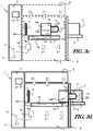
figure 3a représente une vue schématique d'une station de mesure et d'une enceinte de transport, - la
figure 3b représente une vue similaire à lafigure 3a , au cours d'une première étape du procédé de mesure dans laquelle le port de chargement de la station de mesure s'accouple à la porte de l'enceinte de transport, - la
figure 3c représente une vue similaire à lafigure 3a , au cours d'une deuxième étape d'un procédé de mesure dans laquelle une porte du port de chargement et la porte accouplée sont déplacées dans la chambre à environnement contrôlé, - la
figure 3d représente une vue similaire à lafigure 3a , au cours d'une quatrième étape du procédé de mesure dans laquelle l'interface de mesure enveloppe est accouplée à l'enveloppe rigide, - la
figure 4 montre un exemple de réalisation d'une tête de mesure, - la
figure 5a représente une vue schématique d'une station de mesure selon un deuxième mode de réalisation ne faisant pas partie de l'invention et une enceinte de transport, - la
figure 5b représente une vue similaire à lafigure 5a , au cours d'une première étape du procédé de mesure dans laquelle le port de chargement de la station de mesure s'accouple à la porte de l'enceinte de transport, - la
figure 5c représente une vue similaire à lafigure 5a , au cours d'une deuxième étape du procédé de mesure dans laquelle la porte du port de chargement et la porte accouplée sont déplacées dans la chambre à environnement contrôlé, - la
figure 5d représente une vue similaire à lafigure 5a , au cours d'une quatrième étape du procédé de mesure dans laquelle l'interface de mesure enveloppe est accouplée à l'enveloppe rigide, - la
figure 5e représente une vue similaire à lafigure 5a , au cours d'une septième étape du procédé de mesure dans laquelle la porte est accouplée au module de mesure, - la
figure 6 représente une vue de côté de la porte prise en sandwich entre une interface en creux de mesure porte et la porte du port de chargement, - la
figure 7 représente une vue en perspective d'un troisième mode de réalisation d'une station de mesure de la contamination en particules, et - la
figure 8 représente une vue schématique de la station de mesure en particules de lafigure 7 .
- the
figure 1 is a perspective view of a first embodiment of a station for measuring particle contamination coupled to a transport chamber, - the
figure 2 represents an enlarged view of the rigid envelope of the transport enclosure coupled to the measurement station with the measuring module in measurement position, - the
figure 3a represents a schematic view of a measuring station and a transport enclosure, - the
figure 3b represents a view similar to thefigure 3a during a first step of the measuring method in which the loading port of the measuring station mates with the door of the transport enclosure, - the
figure 3c represents a view similar to thefigure 3a during a second step of a measurement process in which a loading port door and the coupled door are moved in the controlled environment chamber, - the
figure 3d represents a view similar to thefigure 3a during a fourth step of the measuring method in which the envelope measuring interface is coupled to the rigid envelope, - the
figure 4 shows an exemplary embodiment of a measuring head, - the
figure 5a represents a schematic view of a measuring station according to a second embodiment not forming part of the invention and a transport enclosure, - the
figure 5b represents a view similar to thefigure 5a during a first step of the measuring method in which the loading port of the measuring station mates with the door of the transport enclosure, - the
figure 5c represents a view similar to thefigure 5a during a second step of the measurement process in which the loading port door and the coupled door are moved into the controlled environment chamber, - the
figure 5d represents a view similar to thefigure 5a during a fourth step of the measuring method in which the envelope measuring interface is coupled to the rigid envelope, - the
figure 5e represents a view similar to thefigure 5a during a seventh step of the measurement process in which the door is coupled to the measuring module, - the
figure 6 represents a side view of the door sandwiched between a door measurement hollow interface and the door of the loading port, - the
figure 7 represents a perspective view of a third embodiment of a station for measuring particulate contamination, and - the
figure 8 represents a schematic view of the particle measuring station of thefigure 7 .
On a représenté sur la
Bien que les figures illustrent une station de mesure susceptible de s'accoupler à une enceinte de transport de type FOUP, la station de mesure peut être adaptée pour d'autres types d'enceintes de transport pour le convoyage et le stockage atmosphérique de substrats semi-conducteurs telles que notamment celles standardisées de type SMIF, FOSB, RSP ou MRP.Although the figures illustrate a measuring station capable of coupling with a FOUP transport enclosure, the measuring station can be adapted for other types of transport enclosures for the conveying and the atmospheric storage of semi substrates. Conductors such as in particular standardized ones of the SMIF, FOSB, RSP or MRP type.
Ces enceintes de transport présentent une atmosphère intérieure confinée sous pression atmosphérique d'air ou d'azote, c'est-à-dire à une pression sensiblement équivalente à celle de l'environnement d'utilisation de la salle blanche, mais séparée de celle-ci.These transport enclosures have an internal atmosphere confined at atmospheric pressure of air or nitrogen, that is to say at a pressure substantially equivalent to that of the environment of use of the clean room, but separated from that -this.
Comme on peut le voir sur les
Pour les mesures, les enceintes de transport sont vidées de leurs substrats.For measurements, the transport enclosures are emptied of their substrates.
Comme visible sur la représentation schématique de la
L'atmosphère interne de la chambre à environnement contrôlé 4 est sous pression atmosphérique telle que définie précédemment. La chambre 4 est de type salle blanche. Elle est par exemple certifiée Iso 3, conformément à la norme ISO 146644-1, dite de « mini-environnement ». Pour cela, la chambre à environnement contrôlé 4 peut comporter une unité de filtrage à flux laminaire 6.The internal atmosphere of the controlled
L'unité de filtrage à flux laminaire 6 comporte des filtres à air pour filtrer les particules en provenance de l'air extérieur, qui pénètrent dans la chambre à environnement contrôlé 4. L'unité de filtrage à flux laminaire 6 comporte également des moyens diffuseurs de flux pour diffuser l'air filtré en un flux laminaire, par exemple depuis le haut de la station 1 vers le bas comme schématisé par les flèches FI sur la
La station de mesure 1 comporte une armoire électrique 7 permettant l'alimentation et le logement de toute ou partie des composants électriques de la station. L'armoire électrique 7 est avantageusement déportée latéralement de la chambre à environnement contrôlé 4, de manière à être à l'écart du flux laminaire d'air filtré, évitant ainsi la contamination de la chambre à environnement contrôlé 4 par les différents composants logés dans l'armoire électrique 7.The measuring
La chambre à environnement contrôlé 4 comporte un accès 10 latéral et un port de chargement 8 (« ou load port » en anglais) agencé sous l'accès 10.The controlled
Le port de chargement 8 est susceptible de s'accoupler d'une part à l'enveloppe rigide 2 et d'autre part à la porte 3 de l'enceinte de transport pour déplacer la porte 3 dans la chambre à environnement contrôlé 4 et mettre l'intérieur de l'enveloppe rigide 2 en communication avec l'intérieur de la chambre à environnement contrôlé 4.The
Le port de chargement 8 comporte un plateau 9 permettant la réception et le positionnement d'une enceinte de transport. Le plateau 9 peut comporter un capteur de présence adapté pour contrôler que le modèle d'enceinte de transport est bien celui qui est compatible avec la station de mesure 1 réceptionnant l'enceinte. En outre, pour s'accoupler à l'enveloppe rigide 2, le plateau 9 du port de chargement 8 comporte un moyen d'arrimage pour d'une part, clamper l'enveloppe rigide 2 et d'autre part, l'avancer contre l'accès 10 de la chambre à environnement contrôlé 4 (flèche D1 sur la
Le port de chargement 8 comporte également une porte de port de chargement 11. La porte de port de chargement 11 présente les sensiblement les mêmes dimensions que la porte 3 de l'enceinte de transport. La porte de port de chargement 11 permet notamment de fermer l'accès 10 de la chambre à environnement contrôlé 4 en l'absence d'enceinte de transport. Elle comporte en outre des moyens d'actionnement de verrou pour verrouiller et déverrouiller des organes de verrouillage de la porte 3.The
Les organes de verrouillage de la porte 3, connus en soi, comprennent par exemple des loquets, portés par la porte 3, actionnés en coulissement radial ou latéral et s'engageant dans l'enveloppe rigide 2 de l'enceinte de transport lorsque l'enceinte de transport est fermée.The locking members of the
Une fois les organes de verrouillage déverrouillés, les moyens d'actionnement de verrou solidarisent de manière réversible la porte 3 à la porte de port de chargement 11. L'ensemble des portes 3,11 peut alors être déplacé d'un seul bloc dans la chambre à environnement contrôlé 4. Pour cela, la porte de port de chargement 11 comporte un mécanisme d'actionnement de porte.Once the locking members are unlocked, the lock actuation means reversibly reverses the
Le mécanisme d'actionnement de porte comporte par exemple un premier axe linéaire motorisé (non représenté) permettant une translation linéaire, telle qu'horizontale, comme représentée par la flèche D2 sur la
L'ensemble des portes 3, 11 est déporté hors de la zone frontale de l'accès 10, par exemple à proximité de la paroi interne de la chambre à environnement contrôlé 4 opposée à l'accès 10. Selon un autre exemple non représenté, le mécanisme d'actionnement de porte déplace l'ensemble des portes 3, 11 vers le bas de la chambre à environnement contrôlé 4 plutôt qu'horizontalement.The set of
Lorsque la porte 3 est déplacée à l'écart de l'enveloppe rigide 2, le volume intérieur de l'enveloppe rigide 2 est en communication avec le volume intérieur de la chambre à environnement contrôlé 4.When the
Le module de mesure 5 comporte une interface de mesure enveloppe 16 configurée pour s'accoupler à une enveloppe rigide 2 d'enceinte de transport accouplée à la chambre à environnement contrôlé 4 à la place de la porte 2, une unité de mesure des particules 14 et un mécanisme de déplacement module 15.The
L'interface de mesure enveloppe 16 est munie d'au moins deux buses d'injection 20 configurées pour diriger un jet de gaz sur au moins deux endroits distincts de l'enveloppe rigide 2 accouplée, les orientations respectives des buses d'injection 20 étant fixes par rapport à l'enveloppe rigide 2 accouplée. L'interface de mesure enveloppe 16 comporte également un premier orifice de prélèvement 12 raccordé à l'unité de mesure des particules 14.The
L'orifice de prélèvement 12 et les buses d'injection 20 sont agencés sur une tête de mesure 13 faisant saillie d'une base de l'interface de mesure enveloppe 16.The
Les buses d'injection 20 comportent des injecteurs en matériau dur, tel qu'en rubis, en saphir ou Zircone. Les injecteurs sont des cylindres creux en matériau dur dont le diamètre intérieur peut être défini avec une très haute précision (de l'ordre de quelques µm), ce diamètre interne définissant le couple de débit d'injection du gaz et de variation de pression entre la pression atmosphérique de la chambre à environnement contrôlé 4 et la pression d'arrivée des gaz. Les injecteurs en matériau dur sont inusables, ce qui évite les dérives de dimension dans le temps et assure qu'ils puissent être réalisés très précisément, ce qui permet une bonne reproductibilité des mesures.The injection nozzles 20 comprise injectors made of hard material, such as ruby, sapphire or zirconia. The injectors are hollow cylinders made of hard material whose inner diameter can be defined with a very high precision (of the order of a few μm), this internal diameter defining the torque of the gas injection flow rate and pressure variation between the atmospheric pressure of the controlled
Les injecteurs sont raccordés à des systèmes d'amenée de gaz pourvus de vannes d'isolation (non représentées), passant dans un logement 5a du module de mesure 5. Le gaz injecté est un gaz neutre tel que de l'azote. Les buses d'injection 20 sont en outre pourvues de filtres à particules pour filtrer d'éventuelles particules polluantes du gaz injecté.The injectors are connected to gas supply systems provided with isolation valves (not shown) passing through a
Les buses d'injection 20 sont par exemple configurées pour diriger un jet de gaz dans au moins deux directions perpendiculaires entre elles et perpendiculaires aux parois de l'enveloppe rigide 2 accouplée à la chambre à environnement contrôlé 4 (voir les exemples de jet de gaz représentés en pointillés sur la
La tête de mesure 13 présente une forme générale parallélépipédique sensiblement complémentairement à la forme interne de l'enveloppe rigide 2. Chacune des cinq faces de la tête de mesure 13 faisant saillie de la base de l'interface de mesure enveloppe 16, comporte au moins une buse d'injection 20 de manière à diriger un jet de gaz dans une direction sensiblement orthogonale à la face de la tête de mesure 13. On peut ainsi mesurer individuellement chacune des cinq faces de l'enveloppe rigide 2.The measuring
En outre, chaque face peut comporter plusieurs buses d'injection 20 par exemple configurées pour diriger des jets de gaz dans des directions parallèles entre elles.In addition, each face may comprise
Par exemple et comme représenté sur la
Selon un autre exemple représenté sur la
Pour augmenter la fiabilité de la mesure, on peut par exemple localiser les jets de gaz dans des zones particulièrement critiques de l'enveloppe rigide 2, tel qu'au niveau des fentes de support des substrats ou dans les coins de l'enveloppe rigide 2. On peut aussi couvrir un maximum de la surface de la paroi interne, notamment en augmentant le nombre de buses d'injection 20 par face.To increase the reliability of the measurement, it is possible, for example, to locate the gas jets in particularly critical areas of the
Le premier orifice de prélèvement 12 est par exemple ménagé sur une des faces de la tête de mesure 13.The
La tête de mesure 13 est configurée pour que la distance entre la sortie d'une buse d'injection 20 et la paroi interne d'une enveloppe rigide 2 accouplée soit inférieure à quelques centimètres, telle que comprise entre 1 mm et 10 cm. Pour optimiser l'arrachage des particules, le débit des buses d'injection 20 est par exemple compris entre 10 et 30 l/min, tel que de l'ordre de 20 l/min, suivant le nombre de buses d'injection 20, le débit diminuant avec l'augmentation du nombre de buses d'injection 20. La variation de pression entre la pression atmosphérique de la chambre à environnement contrôlé 4 et la pression d'arrivée des gaz est par exemple de l'ordre de 3 à 4 bars.The measuring
Le mécanisme de déplacement module 15 est configuré pour déplacer l'interface de mesure enveloppe 16 entre une position de repos (
La tête de mesure 13 fait saillie de la base de l'interface de mesure enveloppe 16 en direction de l'accès 10 de la chambre à environnement contrôlé 4. La base de l'interface de mesure enveloppe 16 présente sensiblement la même forme et les mêmes dimensions qu'une porte 3 d'enceinte de transport, pour être facilement accouplée à une enveloppe rigide 2 d'enceinte de transport à la place de la porte 3. La tête de mesure 13 est par exemple solidarisée au centre de la base de l'interface de mesure enveloppe 16.The measuring
Lorsque l'interface de mesure enveloppe 16 est déplacée dans l'enveloppe rigide 2 accouplée à la chambre à environnement contrôlé 4 en position de mesure, l'interface de mesure enveloppe 16 ferme l'enveloppe rigide 2 à la place de la porte 3 en définissant un premier volume de mesure V1 (
La tête de mesure 13 est reçue dans ce premier volume de mesure V1, ce qui place l'intérieur de l'enveloppe rigide 2 en communication avec le premier orifice de prélèvement 12 raccordé à l'unité de mesure des particules 14, ainsi qu'avec les buses d'injection 20. On profite ainsi de la forme en coquille de l'enveloppe périphérique de l'enceinte de transport pour définir un premier volume de mesure V1 entre l'enveloppe rigide 2 et l'interface de mesure enveloppe 16. La mesure est alors réalisée dans ce premier volume de mesure V1 séparé du reste de la station de mesure 1.The measuring
L'interface de mesure enveloppe 16 ne referme pas l'enveloppe rigide 2 de manière étanche, mais ménage un faible premier interstice entre les deux pour le passage d'un flux de fuite. Le flux d'injection de gaz injecté dans les buses d'injection 20 est dimensionné pour placer le premier volume de mesure V1 en légère surpression par rapport à l'environnement extérieur, favorisant ainsi le sens du flux de gaz vers l'extérieur à travers le premier interstice entre l'interface de mesure enveloppe 16 et l'enveloppe rigide 2, ce qui réduit les risques de contamination en particules.The
L'unité de mesure des particules 14 comporte par exemple une pompe à vide 17, un compteur de particules 18 raccordé en amont de la pompe à vide 17 et une ligne de prélèvement 19 en amont du compteur de particules 18 comme illustré en
La ligne de prélèvement 19 est raccordée à son extrémité au premier orifice de prélèvement 12 de la tête de mesure 13. La ligne de prélèvement 19 peut comporter une première vanne d'isolation 19a agencée entre le premier orifice de prélèvement 12 et le compteur de particules 18. La ligne de prélèvement 19 est suffisamment souple et longue pour permettre les déplacements de la tête de mesure 13. L'unité de mesure des particules 14 peut comporter par exemple une chaîne porte-câble pour porter et guider la ligne de prélèvement 19. Le compteur de particules 18 est par exemple logé dans la chambre à environnement contrôlé 4, au plus près de l'orifice de prélèvement 12 de manière à limiter la longueur de la ligne de prélèvement 19 raccordée au compteur de particules 18.The
En outre, l'unité de mesure des particules 14 peut comporter des moyens de nettoyage 29 configurés pour injecter un gaz de purge dans la ligne de prélèvement 19 afin de la purger des particules qui y seraient éventuellement logées.In addition, the
L'échantillon de gaz est prélevé dans le premier volume de mesure V1 de l'enveloppe rigide 2 accouplée à l'interface de mesure enveloppe 16 par aspiration par le premier orifice de prélèvement 12 de la tête de mesure 13. La quantité de particules contenues dans l'échantillon de gaz prélevé est déterminée par le compteur de particules 18. Le compteur de particules 18 est par exemple de type aérosol, c'est-à-dire qu'il permet de donner une information quantitative des particules en suspension dans un environnement gazeux. Il est par exemple basé sur la technologie laser. Le flux de pompage de la pompe à vide 17 est par exemple de l'ordre de 1,7 m3/h.The gas sample is taken from the first measurement volume V1 of the
Les moyens de positionnement, les moyens de contrôle du modèle d'enceinte de transport, les moyens d'actionnement de verrou, les mécanismes d'actionnement de porte du port de chargement et les moyens d'injection de gaz sont pilotés par une unité de traitement 27 de la station de mesure 1. L'unité de traitement 27 est en outre configurée pour commander l'injection sélective du gaz dans les buses d'injection 20. L'unité de traitement 27 est raccordée à une interface utilisateur 28, comprenant par exemple notamment un écran et un clavier visibles sur la
En position de repos, le module de mesure 5 est agencé dans la chambre à environnement contrôlé 4 dont l'accès 10 est fermée par la porte de port de chargement 11 (
Puis, lorsqu'un opérateur ou un robot place une enceinte de transport sur le plateau 9 du port de chargement 8, le port de chargement 8 positionne et contrôle le modèle d'enceinte de transport, puis clampe l'enveloppe rigide 2 de l'enceinte et l'avance contre l'accès 10 de la chambre à environnement contrôlé 4 (flèche D1 sur la
Les moyens d'actionnement de verrou de la porte de port de chargement 11 déverrouillent alors les organes de verrouillage de la porte 3 et solidarisent la porte 3 à la porte de port de chargement 11 (première étape,
L'ensemble des portes 3-11 est alors déplacé dans la chambre à environnement contrôlé 4 à l'écart de l'accès 10 (flèche D1 sur la
Dans une troisième étape, l'interface de mesure enveloppe 16 est déplacée en direction de l'enveloppe rigide 2.In a third step, the
Dans une quatrième étape, l'interface de mesure enveloppe 16 s'accouple à l'enveloppe rigide 2 à la place de la porte 3. A l'état accouplé, la tête de mesure 13 est immobilisée dans le premier volume de mesure V1 définit par l'interface de mesure enveloppe 16 et l'enveloppe rigide 2 accouplée (position de mesure). Ce premier volume de mesure V1 est donc en communication d'une part, avec le premier orifice de prélèvement 12 ménagé dans la tête de mesure 13 et raccordé à l'unité de mesure des particules 14 et d'autre part, avec les buses d'injection 20 de la tête de mesure 13 (
Dans une cinquième étape, un jet de gaz est injecté simultanément dans les buses d'injection 20 de même orientation. Par exemple, un jet de gaz est injecté dans les quatre buses d'injection 20 d'une même face de la tête de mesure 13. Le jet de gaz décroche un échantillon de particules présentes sur les parois internes de l'enveloppe rigide 2 accouplée. La distance entre les sorties des buses d'injection 20 et les parois interne est maîtrisée (du fait notamment des dimensions de la tête de mesure 13), ce qui permet de décrocher les particules de façon reproductible d'une enceinte de transport à l'autre.In a fifth step, a jet of gas is injected simultaneously into the
Le gaz est prélevé dans le premier volume de mesure V1 par aspiration par la ligne de prélèvement 19. La quantité de particules contenues dans l'échantillon de gaz prélevé est déterminée en continu par le compteur de particules 18.The gas is taken from the first measurement volume V1 by suction via the
Le flux d'injection de gaz place le premier volume de mesure V1 en légère surpression par rapport à l'environnement extérieur, favorisant ainsi le sens du flux de gaz vers l'extérieur, ce qui réduit les risques de contamination en particules de l'enveloppe rigide 2.The gas injection flow places the first measurement volume V1 in slight overpressure with respect to the external environment, thus favoring the direction of the gas flow. outward, which reduces the risk of particulate contamination of the
Le soufflage est alors réalisé au travers des buses d'injections 20 d'orientation fixe, pour décrocher les particules et réaliser une mesure sans pièce mobile dans le volume confiné de l'enveloppe rigide 2 fermé par l'interface de mesure enveloppe 16. On assure ainsi un soufflage au plus proche des parois internes de l'enveloppe rigide 2, sans mouvement des buses d'injection 20 au moment du soufflage.The blowing is then performed through
On profite en outre de la forme en coquille de l'enveloppe périphérique 2 de l'enceinte de transport pour définir un volume de mesure confiné, séparé de la chambre à environnement contrôlé.In addition, the shell shape of the
Puis l'opération de mesure est réitérée pour les buses d'injection 20 de même orientation de chaque face de la tête de mesure 13.Then the measuring operation is repeated for the
L'unité de traitement 27 informe l'utilisateur de l'état de propreté face par face de l'enceinte de transport.The
Lorsque les mesures sont terminées, la tête de mesure 13 est retirée de l'enveloppe rigide 2 et l'enceinte de transport est refermée et libérée pour être envoyée soit au nettoyage, soit pour poursuivre l'opération de convoyage ou de stockage, selon son état de propreté.When the measurements are completed, the measuring
Selon un deuxième mode de réalisation représenté sur les
Pour cela, le module de mesure 5 comporte une interface en creux de mesure porte 21 configurée pour s'accoupler à la porte 3 en définissant un deuxième volume de mesure V2 entre une face de mesure 22 du module de mesure 5 et la porte 3 en vis-à-vis (
La face de mesure 22 présente au moins une buse d'injection 23 et un deuxième orifice de prélèvement 24. Par exemple, la face de mesure 22 comporte quatre buses d'injection 23. L'interface en creux de mesure porte 21 met alors en communication l'intérieur du deuxième volume de mesure V2 avec le deuxième orifice de prélèvement 24 raccordé à l'unité de mesure des particules 14 et avec les buses d'injection 23.The measuring
Etant donné que la porte 3 ne permet pas de prédéfinir une portion volumique pour confiner les particules décrochées à mesurer, c'est l'interface en creux de mesure porte 21 qui est adaptée pour définir un deuxième volume de mesure V2 dans lequel les buses d'injection 23 soufflent pour décrocher les particules de la porte 3 et dans lequel un deuxième orifice de prélèvement 24 raccordé à l'unité de mesure des particules 14 prélève l'échantillon gazeux au moment de la réalisation d'une mesure (
L'interface en creux de mesure porte 21 présente par exemple une forme générale de cadre dont les dimensions périphériques sont sensiblement équivalentes à celles d'une porte 3 et dont l'épaisseur est sensiblement équivalente à la distance optimale entre la sortie d'une buse d'injection 20 et la paroi interne d'une enveloppe rigide 2 accouplée. La distance optimale est de l'ordre de quelques centimètres telle que comprise entre 1 et 10 cm. Le deuxième volume de mesure V2 représente ainsi un volume d'environ un cinquième du volume interne de l'enceinte de transport.The hollow
Les buses d'injection 23 sont similaires aux buses d'injection 20 de la tête de mesure 13 et sont par exemple configurées pour diriger un jet de gaz dans une direction sensiblement orthogonale à la face de mesure 22 (voir les exemples de jet de gaz représentés en pointillés sur la
L'interface en creux de mesure porte 21 ne se referme pas de manière étanche sur la porte 3, mais ménage un faible deuxième interstice entre les deux pour le passage d'un flux de fuite. Le flux d'injection de gaz injecté dans les buses d'injection 20 est dimensionné pour placer le deuxième volume de mesure V2 en légère surpression par rapport à l'environnement extérieur, favorisant ainsi le sens du flux de gaz vers l'extérieur à travers le deuxième interstice entre l'interface en creux de mesure porte 21 et la porte 21, ce qui réduit les risques de contamination en particules.The hollow
L'interface de mesure enveloppe 16 et l'interface en creux de mesure porte 21 sont par exemple agencées dos à dos. La tête de mesure 13 est susceptible d'être translatée dans l'enveloppe rigide 2 accouplée et la porte 3 est susceptible d'être translatée en direction de l'interface en creux de mesure porte 21.The
La ligne de prélèvement 19 comporte un dispositif à vanne pour basculer sélectivement vers le premier ou le deuxième orifice de prélèvement 12, 24 (
Le dispositif à vanne comporte par exemple une première vanne d'isolation 19a agencée entre le premier orifice de prélèvement 12 et le compteur de particules 18 et une deuxième vanne d'isolation 19b agencée entre le deuxième orifice de prélèvement 24 et le compteur de particules 18. Les première et deuxième vannes d'isolation 19a, 19b peuvent être pilotées par l'unité de traitement 27 pour mesurer sélectivement la porte 3 de l'enceinte de transport ou une des parois internes de l'enveloppe rigide 2. On utilise ainsi un seul compteur de particules 18 pour mesurer à la fois la porte 3 et les parois internes de l'enveloppe rigide 2. Selon un autre exemple, le dispositif à vanne comporte une vanne trois voies.The valve device comprises, for example, a
En fonctionnement, les cinq premières étapes sont similaires au procédé de mesure précédemment décrit.In operation, the first five steps are similar to the previously described measurement method.
Dans une première étape, le port de chargement 8 de la station de mesure 1 s'accouple à la porte 3 de l'enceinte de transport (
Au cours d'une deuxième étape, la porte du port de chargement 11 et la porte 3 accouplée sont déplacées dans la chambre à environnement contrôlé 4 (
Puis, au cours d'une troisième étape, l'interface de mesure enveloppe 16 est déplacée en direction de l'enveloppe rigide 2.Then, in a third step, the
Puis, au cours d'une quatrième étape, l'interface de mesure enveloppe 16 s'accouple à l'enveloppe rigide 2 (
Une fois que l'interface de mesure enveloppe 16 est accouplée à l'enveloppe rigide 2 (position de mesure), la porte de port de chargement 11 et la porte 3 accouplée sont déplacées en direction de l'interface en creux de mesure porte 21 par l'action du mécanisme d'actionnement de porte (sixième étape, flèche D4 sur la
Puis dans une septième étape, la porte 3 s'accouple au module de mesure 5 en définissant un deuxième volume de mesure V2 entre une face de mesure du module de mesure 5 et la porte 3 en vis-à-vis (
Dans une huitième étape, les buses d'injection 23 injectent un jet de gaz en direction de la porte 3. Le jet de gaz décroche un échantillon de particules présentes sur la porte 3. La distance entre les sorties des buses d'injection 23 et la porte 3 est maîtrisée, ce qui permet de décrocher les particules de façon reproductible d'une enceinte de transport à l'autre.In an eighth step, the
Le gaz est prélevé dans le deuxième volume de mesure V2 par aspiration par la ligne de prélèvement 19 après fermeture de la première vanne d'isolation 19a et ouverture de la deuxième vanne d'isolation 19b. La quantité de particules contenues dans l'échantillon de gaz prélevé est déterminée en continu par le compteur de particules 18. Le flux d'injection de gaz place le deuxième volume de mesure V2 en légère surpression par rapport à l'environnement extérieur, favorisant ainsi le sens du flux de gaz vers l'extérieur à travers le deuxième interstice entre l'interface en creux de mesure porte 21 et la porte 3, ce qui réduit les risques de contamination en particules.The gas is taken from the second measurement volume V2 by suction via the
L'unité de traitement 27 informe l'utilisateur de l'état de propreté face par face de l'enceinte de transport, y compris la porte 3.The
Lorsque les mesures sont terminées, l'ensemble de portes 3, 11 est déplacé à l'écart de l'interface en creux de mesure porte 21, la tête de mesure 13 est retirée de l'enveloppe rigide 2 et l'enceinte de transport est refermée soit pour être envoyée au nettoyage, soit pour poursuivre l'opération de transport et de de convoyage selon son état de propreté.When the measurements are completed, the set of
Selon un troisième mode de réalisation de la station de mesure représentée sur les
Chaque port de chargement 8a, 8b comporte son propre mécanisme d'actionnement de porte 25a, 25b.Each
Le mécanisme de déplacement module 26 est par exemple configuré pour déplacer l'interface de mesure enveloppe 16 entre une position de repos et une position de mesure dans l'une ou l'autre des enveloppe rigides 2 accouplées. Pour cela, le mécanisme de déplacement module 26 permet par exemple de déporter l'interface de mesure enveloppe 16 latéralement à son déplacement axial vers la chambre à environnement contrôlé 4. L'interface de mesure enveloppe 16 peut ainsi être déportée de l'accès 10 de la chambre à environnement contrôlé 4 pour laisser libre champ au mécanisme d'actionnement de porte 25a ou 25b.The
Claims (13)
- Station for measuring particle contamination of a transport carrier for conveying and storing semiconductor substrates at atmospheric pressure, said transport carrier comprising a rigid casing (2) having an aperture and a removable door (3) allowing the aperture to be closed, the measuring station comprising:- a controlled environment chamber (4) comprising at least one load port (8) capable of coupling, on the one hand, to the rigid casing (2), and on the other hand, to the door (3) of the transport carrier, in order to move the door (3) into the controlled environment chamber (4) and bring the interior of the rigid casing (2) into communication with the interior of the controlled environment chamber (4); and- a measuring module (5) comprising a particle measuring unit (14) and a casing-measuring interface (16) configured to couple to the rigid transport carrier casing (2) coupled to the controlled environment chamber (4) in the place of the door (3),said casing-measuring interface (16) comprising a measuring head (13) protruding from a base of the casing-measuring interface (16), bearing a first sampling orifice (12) connected to the particle measuring unit (14), characterized in that said measuring head (13) comprises at least five injecting nozzles (20) configured to direct a gas jet onto at least five separate locations on the rigid casing (2) coupled to the controlled environment chamber (4), the respective orientations of the injecting nozzles (20) being fixed relative to the coupled rigid casing (2), said measuring head (13) having a generally parallelepipedal shape and each of the five faces of the measuring head (13) protruding from the base of the casing-measuring interface (16) comprising at least one injecting nozzle (20).
- Measuring station according to Claim 1, characterized in that the measuring module (5) comprises a module-moving mechanism (15; 26) configured to move the casing-measuring interface (16) between a rest position and a measuring position in the coupled rigid casing (2).
- Measuring station according to either of Claims 1 and 2, characterized in that it comprises a processing unit (27) configured to control selective injection of the gas into the injecting nozzles (20).
- Measuring station according to one of the preceding claims, in combination with Claim 2, characterized in that the actuator of the module-moving mechanism (15; 26) is arranged in the controlled environment chamber (4), and in that the controlled environment chamber (4) comprises a filtering laminar flow unit (6) for placing the internal atmosphere of the controlled environment chamber (4) under a laminar flow of filtered air.
- Measuring station according to the preceding claim, characterized in that it comprises an electrical cabinet (7) located beside the controlled environment chamber (4), said electrical cabinet (7) housing a vacuum pump (17) of the particle measuring unit (14).
- Measuring station according to one of the preceding claims, characterized in that the injecting nozzles (20) are configured to direct a gas jet in at least two directions that are perpendicular to one another and perpendicular to the walls of a rigid transport carrier casing (2) coupled to the controlled environment chamber (4).
- Measuring station according to one of the preceding claims, characterized in that the particle measuring unit (14) comprises cleaning means (29) configured to inject a purging gas into the sampling line (19).
- Measuring station according to one of the preceding claims, characterized in that the controlled environment chamber (4) comprises two load ports (8a, 8b) capable of coupling to a respective transport carrier.
- Method for measuring particle contamination of a transport carrier for conveying and storing semiconductor substrates at atmospheric pressure, characterized in that it is implemented in a measuring station according to one of the preceding claims, and in that it comprises a step in which a gas jet is injected into the injecting nozzles (20) of said casing-measuring interface (16) after said casing-measuring interface (16) has been coupled to the rigid casing (2).
- Measuring method according to the preceding claim, characterized in that an interstice is left between the casing-measuring interface (16) and the rigid casing (2) coupled to the casing-measuring interface (16), and in that the injected gas jet is parameterized to generate a leakage gas flow, through the interstice, directed towards the exterior of the rigid casing (2).
- Measuring method according to either of Claims 9 and 10, characterized in that said casing-measuring interface (16) is moved into the rigid casing (2) coupled to the controlled environment chamber (4).
- Measuring method according to one of Claims 9 to 11, characterized in that a gas jet is injected into a preset number of injecting nozzles (20) at the same time.
- Measuring method according to the preceding claim, characterized in that a gas jet is injected simultaneously into all the injecting nozzles (20) of a given orientation.
Applications Claiming Priority (2)
| Application Number | Priority Date | Filing Date | Title |
|---|---|---|---|
| FR1261451A FR2999015B1 (en) | 2012-11-30 | 2012-11-30 | STATION AND METHOD FOR MEASURING CONTAMINATION IN PARTICLES OF A TRANSPORT ENCLOSURE FOR CONVEYING AND ATMOSPHERIC STORAGE OF SEMICONDUCTOR SUBSTRATES |
| PCT/EP2013/075075 WO2014083151A1 (en) | 2012-11-30 | 2013-11-29 | Station and method for measuring particulate contamination of a transport chamber for conveying and atmospherically storing semiconductor substrates |
Publications (2)
| Publication Number | Publication Date |
|---|---|
| EP2926370A1 EP2926370A1 (en) | 2015-10-07 |
| EP2926370B1 true EP2926370B1 (en) | 2017-07-12 |
Family
ID=47666355
Family Applications (1)
| Application Number | Title | Priority Date | Filing Date |
|---|---|---|---|
| EP13817657.3A Active EP2926370B1 (en) | 2012-11-30 | 2013-11-29 | Station and method for measuring particulate contamination of a transport chamber for conveying and atmospherically storing semiconductor substrates |
Country Status (8)
| Country | Link |
|---|---|
| US (1) | US9810617B2 (en) |
| EP (1) | EP2926370B1 (en) |
| JP (1) | JP6374878B2 (en) |
| KR (1) | KR102179366B1 (en) |
| CN (1) | CN104813461B (en) |
| FR (1) | FR2999015B1 (en) |
| TW (1) | TWI614829B (en) |
| WO (1) | WO2014083151A1 (en) |
Families Citing this family (7)
| Publication number | Priority date | Publication date | Assignee | Title |
|---|---|---|---|---|
| KR102313961B1 (en) * | 2016-04-14 | 2021-10-15 | 어플라이드 머티어리얼스, 인코포레이티드 | 30 NM In-Line LPC Testing and Cleaning of Semiconductor Processing Equipment |
| JP7234527B2 (en) * | 2018-07-30 | 2023-03-08 | Tdk株式会社 | Filter structure with built-in sensor and wafer storage container |
| JP7411641B2 (en) * | 2018-09-12 | 2024-01-11 | ラム リサーチ コーポレーション | Particle measurement method and particle measurement device |
| FR3101001B1 (en) * | 2019-09-25 | 2022-05-27 | Pfeiffer Vacuum | Station and method for cleaning a transport enclosure for the conveying and atmospheric storage of semiconductor substrates |
| KR102140063B1 (en) * | 2020-01-30 | 2020-08-03 | 주식회사 위드텍 | Particle measuring device for wafer carrier |
| FR3139663A1 (en) | 2022-09-13 | 2024-03-15 | Pfeiffer Vacuum | Station and method for measuring particle contamination of a transport enclosure for the conveying and atmospheric storage of semiconductor wafers |
| DE102022124334A1 (en) * | 2022-09-22 | 2024-03-28 | Gsec German Semiconductor Equipment Company Gmbh | Device and method for cleaning cup-shaped hollow bodies, in particular transport containers for semiconductor wafers or for EUV lithography masks |
Family Cites Families (12)
| Publication number | Priority date | Publication date | Assignee | Title |
|---|---|---|---|---|
| US5879458A (en) * | 1996-09-13 | 1999-03-09 | Semifab Incorporated | Molecular contamination control system |
| JPH11274282A (en) * | 1998-03-23 | 1999-10-08 | Toshiba Corp | Substrate housing vessel, substrate housing vessel cleaner, substrate housing cleaning method and substrate treating apparatus |
| US6923188B2 (en) * | 2003-04-29 | 2005-08-02 | Powerchip Semiconductor Corp. | Method of sampling contaminants of semiconductor wafer carrier |
| FR2883412B1 (en) * | 2005-03-18 | 2007-05-04 | Alcatel Sa | METHOD AND DEVICE FOR CONTROLLING THE CONTAMINATION OF SUBSTRATE PADS |
| DE102005030275A1 (en) * | 2005-06-21 | 2006-12-28 | Dynamic Microsystems Semiconductor Equipment Gmbh | Method for cleaning or drying pot-like hollow bodies involves flushing head with outer shape, which is largely complementary to the inner shape of the interior is introduced into the interior |
| US20070062561A1 (en) * | 2005-09-19 | 2007-03-22 | International Business Machines Corporation | Method And Apparatus For Testing Particulate Contamination In Wafer Carriers |
| JP4264115B2 (en) * | 2007-07-31 | 2009-05-13 | Tdk株式会社 | Containment processing method and lid opening / closing system used in the method |
| FR2920046A1 (en) * | 2007-08-13 | 2009-02-20 | Alcatel Lucent Sas | METHOD FOR POST-PROCESSING A TRANSPORT MEDIUM FOR THE CONVEYAGE AND ATMOSPHERIC STORAGE OF SEMICONDUCTOR SUBSTRATES, AND POST-PROCESSING STATION FOR IMPLEMENTING SUCH A METHOD |
| FR2930675B1 (en) | 2008-04-24 | 2010-08-20 | Alcatel Lucent | STATION FOR MEASURING CONTAMINATION IN PARTICULAR OF A TRANSPORT ENCLOSURE FOR CONVEYING AND ATMOSPHERIC STORAGE OF SEMICONDUCTOR SUBSTRATES AND CORRESPONDING MEASUREMENT METHOD |
| JP5189114B2 (en) * | 2010-01-29 | 2013-04-24 | 東京エレクトロン株式会社 | Substrate processing apparatus and substrate processing method |
| JP2011159834A (en) * | 2010-02-01 | 2011-08-18 | Yaskawa Electric Corp | Substrate carrier device with gas replacement device, substrate carrier system, and replacement method |
| FR2961946B1 (en) * | 2010-06-29 | 2012-08-03 | Alcatel Lucent | TREATMENT DEVICE FOR TRANSPORT AND STORAGE BOXES |
-
2012
- 2012-11-30 FR FR1261451A patent/FR2999015B1/en not_active Expired - Fee Related
-
2013
- 2013-11-28 TW TW102143557A patent/TWI614829B/en active
- 2013-11-29 CN CN201380062094.9A patent/CN104813461B/en active Active
- 2013-11-29 KR KR1020157015881A patent/KR102179366B1/en active IP Right Grant
- 2013-11-29 EP EP13817657.3A patent/EP2926370B1/en active Active
- 2013-11-29 JP JP2015544476A patent/JP6374878B2/en active Active
- 2013-11-29 WO PCT/EP2013/075075 patent/WO2014083151A1/en active Application Filing
- 2013-11-29 US US14/441,669 patent/US9810617B2/en active Active
Also Published As
| Publication number | Publication date |
|---|---|
| CN104813461A (en) | 2015-07-29 |
| US9810617B2 (en) | 2017-11-07 |
| KR20150092170A (en) | 2015-08-12 |
| EP2926370A1 (en) | 2015-10-07 |
| JP6374878B2 (en) | 2018-08-15 |
| TWI614829B (en) | 2018-02-11 |
| WO2014083151A1 (en) | 2014-06-05 |
| FR2999015B1 (en) | 2014-12-12 |
| CN104813461B (en) | 2018-04-27 |
| KR102179366B1 (en) | 2020-11-16 |
| FR2999015A1 (en) | 2014-06-06 |
| JP2015535660A (en) | 2015-12-14 |
| TW201440164A (en) | 2014-10-16 |
| US20150276572A1 (en) | 2015-10-01 |
Similar Documents
| Publication | Publication Date | Title |
|---|---|---|
| EP2926370B1 (en) | Station and method for measuring particulate contamination of a transport chamber for conveying and atmospherically storing semiconductor substrates | |
| EP0892985B1 (en) | Transport device for flat objects and process of transfer of these objects between the device and a treatment apparatus | |
| EP2272083B1 (en) | Station and method for measuring the contamination of an enclosure used for transporting semiconductor substrates | |
| FR2902235A1 (en) | DEVICE FOR TRANSPORTING, STORING AND TRANSFERRING SUBSTRATES | |
| EP0593366B1 (en) | Flat confinement housing for a flat object in a special atmosphere | |
| FR2668301A1 (en) | METHOD AND INSTALLATION OF TRANSFER WITHOUT CONTAMINATION. | |
| EP2926369B1 (en) | Station and method for measuring the particulate contamination of a transport chamber for conveying and atmospherically storing semiconductor substrates | |
| FR2920046A1 (en) | METHOD FOR POST-PROCESSING A TRANSPORT MEDIUM FOR THE CONVEYAGE AND ATMOSPHERIC STORAGE OF SEMICONDUCTOR SUBSTRATES, AND POST-PROCESSING STATION FOR IMPLEMENTING SUCH A METHOD | |
| FR2961946A1 (en) | TREATMENT DEVICE FOR TRANSPORT AND STORAGE BOXES | |
| EP0891629A1 (en) | Coupling system for the transfer of a confined planar object from a containment pod to an object processing unit | |
| EP0964434A2 (en) | Adapter device for confinement boxes with at least one flat object in ultra-clean atmosphere | |
| EP2657364A1 (en) | Reactor for atomic layer deposition (ALD), use for encapsulating an OLED device by depositing a transparent layer of Al2O3 | |
| EP0598633A1 (en) | Handling and processing system for workpieces in individual boxes | |
| EP1973153A1 (en) | Sealed chamber for transport and storage of semiconductor substrates | |
| EP0504053B1 (en) | Autonomous container for treating an object under vacuum and transfer lock | |
| FR3101001A1 (en) | Station and method for cleaning a transport enclosure for conveying and atmospheric storage of semiconductor substrates | |
| FR3139663A1 (en) | Station and method for measuring particle contamination of a transport enclosure for the conveying and atmospheric storage of semiconductor wafers | |
| FR3139904A1 (en) | Device for measuring gas contamination of a semiconductor substrate transport enclosure and associated measurement method |
Legal Events
| Date | Code | Title | Description |
|---|---|---|---|
| PUAI | Public reference made under article 153(3) epc to a published international application that has entered the european phase |
Free format text: ORIGINAL CODE: 0009012 |
|
| 17P | Request for examination filed |
Effective date: 20150507 |
|
| AK | Designated contracting states |
Kind code of ref document: A1 Designated state(s): AL AT BE BG CH CY CZ DE DK EE ES FI FR GB GR HR HU IE IS IT LI LT LU LV MC MK MT NL NO PL PT RO RS SE SI SK SM TR |
|
| AX | Request for extension of the european patent |
Extension state: BA ME |
|
| RAP1 | Party data changed (applicant data changed or rights of an application transferred) |
Owner name: PFEIFFER VACUUM |
|
| DAX | Request for extension of the european patent (deleted) | ||
| RIC1 | Information provided on ipc code assigned before grant |
Ipc: G01N 15/10 20060101ALI20161205BHEP Ipc: H01L 21/673 20060101AFI20161205BHEP |
|
| GRAP | Despatch of communication of intention to grant a patent |
Free format text: ORIGINAL CODE: EPIDOSNIGR1 |
|
| INTG | Intention to grant announced |
Effective date: 20170309 |
|
| GRAS | Grant fee paid |
Free format text: ORIGINAL CODE: EPIDOSNIGR3 |
|
| GRAA | (expected) grant |
Free format text: ORIGINAL CODE: 0009210 |
|
| AK | Designated contracting states |
Kind code of ref document: B1 Designated state(s): AL AT BE BG CH CY CZ DE DK EE ES FI FR GB GR HR HU IE IS IT LI LT LU LV MC MK MT NL NO PL PT RO RS SE SI SK SM TR |
|
| REG | Reference to a national code |
Ref country code: GB Ref legal event code: FG4D Free format text: NOT ENGLISH |
|
| REG | Reference to a national code |
Ref country code: CH Ref legal event code: EP |
|
| REG | Reference to a national code |
Ref country code: AT Ref legal event code: REF Ref document number: 909091 Country of ref document: AT Kind code of ref document: T Effective date: 20170715 |
|
| REG | Reference to a national code |
Ref country code: IE Ref legal event code: FG4D Free format text: LANGUAGE OF EP DOCUMENT: FRENCH |
|
| REG | Reference to a national code |
Ref country code: DE Ref legal event code: R096 Ref document number: 602013023533 Country of ref document: DE |
|
| REG | Reference to a national code |
Ref country code: NL Ref legal event code: MP Effective date: 20170712 |
|
| REG | Reference to a national code |
Ref country code: FR Ref legal event code: PLFP Year of fee payment: 5 |
|
| REG | Reference to a national code |
Ref country code: LT Ref legal event code: MG4D |
|
| REG | Reference to a national code |
Ref country code: AT Ref legal event code: MK05 Ref document number: 909091 Country of ref document: AT Kind code of ref document: T Effective date: 20170712 |
|
| PG25 | Lapsed in a contracting state [announced via postgrant information from national office to epo] |
Ref country code: NO Free format text: LAPSE BECAUSE OF FAILURE TO SUBMIT A TRANSLATION OF THE DESCRIPTION OR TO PAY THE FEE WITHIN THE PRESCRIBED TIME-LIMIT Effective date: 20171012 Ref country code: NL Free format text: LAPSE BECAUSE OF FAILURE TO SUBMIT A TRANSLATION OF THE DESCRIPTION OR TO PAY THE FEE WITHIN THE PRESCRIBED TIME-LIMIT Effective date: 20170712 Ref country code: HR Free format text: LAPSE BECAUSE OF FAILURE TO SUBMIT A TRANSLATION OF THE DESCRIPTION OR TO PAY THE FEE WITHIN THE PRESCRIBED TIME-LIMIT Effective date: 20170712 Ref country code: LT Free format text: LAPSE BECAUSE OF FAILURE TO SUBMIT A TRANSLATION OF THE DESCRIPTION OR TO PAY THE FEE WITHIN THE PRESCRIBED TIME-LIMIT Effective date: 20170712 Ref country code: FI Free format text: LAPSE BECAUSE OF FAILURE TO SUBMIT A TRANSLATION OF THE DESCRIPTION OR TO PAY THE FEE WITHIN THE PRESCRIBED TIME-LIMIT Effective date: 20170712 Ref country code: SE Free format text: LAPSE BECAUSE OF FAILURE TO SUBMIT A TRANSLATION OF THE DESCRIPTION OR TO PAY THE FEE WITHIN THE PRESCRIBED TIME-LIMIT Effective date: 20170712 Ref country code: AT Free format text: LAPSE BECAUSE OF FAILURE TO SUBMIT A TRANSLATION OF THE DESCRIPTION OR TO PAY THE FEE WITHIN THE PRESCRIBED TIME-LIMIT Effective date: 20170712 |
|
| PG25 | Lapsed in a contracting state [announced via postgrant information from national office to epo] |
Ref country code: IS Free format text: LAPSE BECAUSE OF FAILURE TO SUBMIT A TRANSLATION OF THE DESCRIPTION OR TO PAY THE FEE WITHIN THE PRESCRIBED TIME-LIMIT Effective date: 20171112 Ref country code: ES Free format text: LAPSE BECAUSE OF FAILURE TO SUBMIT A TRANSLATION OF THE DESCRIPTION OR TO PAY THE FEE WITHIN THE PRESCRIBED TIME-LIMIT Effective date: 20170712 Ref country code: RS Free format text: LAPSE BECAUSE OF FAILURE TO SUBMIT A TRANSLATION OF THE DESCRIPTION OR TO PAY THE FEE WITHIN THE PRESCRIBED TIME-LIMIT Effective date: 20170712 Ref country code: PL Free format text: LAPSE BECAUSE OF FAILURE TO SUBMIT A TRANSLATION OF THE DESCRIPTION OR TO PAY THE FEE WITHIN THE PRESCRIBED TIME-LIMIT Effective date: 20170712 Ref country code: GR Free format text: LAPSE BECAUSE OF FAILURE TO SUBMIT A TRANSLATION OF THE DESCRIPTION OR TO PAY THE FEE WITHIN THE PRESCRIBED TIME-LIMIT Effective date: 20171013 Ref country code: LV Free format text: LAPSE BECAUSE OF FAILURE TO SUBMIT A TRANSLATION OF THE DESCRIPTION OR TO PAY THE FEE WITHIN THE PRESCRIBED TIME-LIMIT Effective date: 20170712 Ref country code: BG Free format text: LAPSE BECAUSE OF FAILURE TO SUBMIT A TRANSLATION OF THE DESCRIPTION OR TO PAY THE FEE WITHIN THE PRESCRIBED TIME-LIMIT Effective date: 20171012 |
|
| REG | Reference to a national code |
Ref country code: DE Ref legal event code: R097 Ref document number: 602013023533 Country of ref document: DE |
|
| PG25 | Lapsed in a contracting state [announced via postgrant information from national office to epo] |
Ref country code: DK Free format text: LAPSE BECAUSE OF FAILURE TO SUBMIT A TRANSLATION OF THE DESCRIPTION OR TO PAY THE FEE WITHIN THE PRESCRIBED TIME-LIMIT Effective date: 20170712 Ref country code: RO Free format text: LAPSE BECAUSE OF FAILURE TO SUBMIT A TRANSLATION OF THE DESCRIPTION OR TO PAY THE FEE WITHIN THE PRESCRIBED TIME-LIMIT Effective date: 20170712 Ref country code: CZ Free format text: LAPSE BECAUSE OF FAILURE TO SUBMIT A TRANSLATION OF THE DESCRIPTION OR TO PAY THE FEE WITHIN THE PRESCRIBED TIME-LIMIT Effective date: 20170712 |
|
| PLBE | No opposition filed within time limit |
Free format text: ORIGINAL CODE: 0009261 |
|
| STAA | Information on the status of an ep patent application or granted ep patent |
Free format text: STATUS: NO OPPOSITION FILED WITHIN TIME LIMIT |
|
| PG25 | Lapsed in a contracting state [announced via postgrant information from national office to epo] |
Ref country code: EE Free format text: LAPSE BECAUSE OF FAILURE TO SUBMIT A TRANSLATION OF THE DESCRIPTION OR TO PAY THE FEE WITHIN THE PRESCRIBED TIME-LIMIT Effective date: 20170712 Ref country code: SK Free format text: LAPSE BECAUSE OF FAILURE TO SUBMIT A TRANSLATION OF THE DESCRIPTION OR TO PAY THE FEE WITHIN THE PRESCRIBED TIME-LIMIT Effective date: 20170712 Ref country code: SM Free format text: LAPSE BECAUSE OF FAILURE TO SUBMIT A TRANSLATION OF THE DESCRIPTION OR TO PAY THE FEE WITHIN THE PRESCRIBED TIME-LIMIT Effective date: 20170712 Ref country code: IT Free format text: LAPSE BECAUSE OF FAILURE TO SUBMIT A TRANSLATION OF THE DESCRIPTION OR TO PAY THE FEE WITHIN THE PRESCRIBED TIME-LIMIT Effective date: 20170712 |
|
| 26N | No opposition filed |
Effective date: 20180413 |
|
| PG25 | Lapsed in a contracting state [announced via postgrant information from national office to epo] |
Ref country code: MC Free format text: LAPSE BECAUSE OF FAILURE TO SUBMIT A TRANSLATION OF THE DESCRIPTION OR TO PAY THE FEE WITHIN THE PRESCRIBED TIME-LIMIT Effective date: 20170712 |
|
| GBPC | Gb: european patent ceased through non-payment of renewal fee |
Effective date: 20171129 |
|
| PG25 | Lapsed in a contracting state [announced via postgrant information from national office to epo] |
Ref country code: LI Free format text: LAPSE BECAUSE OF NON-PAYMENT OF DUE FEES Effective date: 20171130 Ref country code: CH Free format text: LAPSE BECAUSE OF NON-PAYMENT OF DUE FEES Effective date: 20171130 |
|
| PG25 | Lapsed in a contracting state [announced via postgrant information from national office to epo] |
Ref country code: SI Free format text: LAPSE BECAUSE OF FAILURE TO SUBMIT A TRANSLATION OF THE DESCRIPTION OR TO PAY THE FEE WITHIN THE PRESCRIBED TIME-LIMIT Effective date: 20170712 Ref country code: LU Free format text: LAPSE BECAUSE OF NON-PAYMENT OF DUE FEES Effective date: 20171129 |
|
| REG | Reference to a national code |
Ref country code: BE Ref legal event code: MM Effective date: 20171130 |
|
| REG | Reference to a national code |
Ref country code: IE Ref legal event code: MM4A |
|
| PG25 | Lapsed in a contracting state [announced via postgrant information from national office to epo] |
Ref country code: MT Free format text: LAPSE BECAUSE OF FAILURE TO SUBMIT A TRANSLATION OF THE DESCRIPTION OR TO PAY THE FEE WITHIN THE PRESCRIBED TIME-LIMIT Effective date: 20170712 |
|
| PG25 | Lapsed in a contracting state [announced via postgrant information from national office to epo] |
Ref country code: IE Free format text: LAPSE BECAUSE OF NON-PAYMENT OF DUE FEES Effective date: 20171129 |
|
| PG25 | Lapsed in a contracting state [announced via postgrant information from national office to epo] |
Ref country code: BE Free format text: LAPSE BECAUSE OF NON-PAYMENT OF DUE FEES Effective date: 20171130 Ref country code: GB Free format text: LAPSE BECAUSE OF NON-PAYMENT OF DUE FEES Effective date: 20171129 |
|
| PG25 | Lapsed in a contracting state [announced via postgrant information from national office to epo] |
Ref country code: HU Free format text: LAPSE BECAUSE OF FAILURE TO SUBMIT A TRANSLATION OF THE DESCRIPTION OR TO PAY THE FEE WITHIN THE PRESCRIBED TIME-LIMIT; INVALID AB INITIO Effective date: 20131129 |
|
| PG25 | Lapsed in a contracting state [announced via postgrant information from national office to epo] |
Ref country code: CY Free format text: LAPSE BECAUSE OF FAILURE TO SUBMIT A TRANSLATION OF THE DESCRIPTION OR TO PAY THE FEE WITHIN THE PRESCRIBED TIME-LIMIT Effective date: 20170712 |
|
| PG25 | Lapsed in a contracting state [announced via postgrant information from national office to epo] |
Ref country code: MK Free format text: LAPSE BECAUSE OF FAILURE TO SUBMIT A TRANSLATION OF THE DESCRIPTION OR TO PAY THE FEE WITHIN THE PRESCRIBED TIME-LIMIT Effective date: 20170712 |
|
| PG25 | Lapsed in a contracting state [announced via postgrant information from national office to epo] |
Ref country code: TR Free format text: LAPSE BECAUSE OF FAILURE TO SUBMIT A TRANSLATION OF THE DESCRIPTION OR TO PAY THE FEE WITHIN THE PRESCRIBED TIME-LIMIT Effective date: 20170712 |
|
| PG25 | Lapsed in a contracting state [announced via postgrant information from national office to epo] |
Ref country code: PT Free format text: LAPSE BECAUSE OF FAILURE TO SUBMIT A TRANSLATION OF THE DESCRIPTION OR TO PAY THE FEE WITHIN THE PRESCRIBED TIME-LIMIT Effective date: 20170712 |
|
| PG25 | Lapsed in a contracting state [announced via postgrant information from national office to epo] |
Ref country code: AL Free format text: LAPSE BECAUSE OF FAILURE TO SUBMIT A TRANSLATION OF THE DESCRIPTION OR TO PAY THE FEE WITHIN THE PRESCRIBED TIME-LIMIT Effective date: 20170712 |
|
| P01 | Opt-out of the competence of the unified patent court (upc) registered |
Effective date: 20230524 |
|
| PGFP | Annual fee paid to national office [announced via postgrant information from national office to epo] |
Ref country code: FR Payment date: 20231127 Year of fee payment: 11 Ref country code: DE Payment date: 20231121 Year of fee payment: 11 |