EP0892982B1 - Angular measurement apparatus - Google Patents
Angular measurement apparatus Download PDFInfo
- Publication number
- EP0892982B1 EP0892982B1 EP97917787A EP97917787A EP0892982B1 EP 0892982 B1 EP0892982 B1 EP 0892982B1 EP 97917787 A EP97917787 A EP 97917787A EP 97917787 A EP97917787 A EP 97917787A EP 0892982 B1 EP0892982 B1 EP 0892982B1
- Authority
- EP
- European Patent Office
- Prior art keywords
- track
- signal
- signals
- base
- measuring
- Prior art date
- Legal status (The legal status is an assumption and is not a legal conclusion. Google has not performed a legal analysis and makes no representation as to the accuracy of the status listed.)
- Expired - Lifetime
Links
- 238000005259 measurement Methods 0.000 title claims abstract description 26
- 238000000034 method Methods 0.000 claims abstract description 21
- 238000012545 processing Methods 0.000 claims description 7
- 230000000737 periodic effect Effects 0.000 claims description 5
- 230000003287 optical effect Effects 0.000 abstract description 30
- 230000010363 phase shift Effects 0.000 description 8
- 238000007619 statistical method Methods 0.000 description 5
- 230000009897 systematic effect Effects 0.000 description 4
- 230000000712 assembly Effects 0.000 description 3
- 238000000429 assembly Methods 0.000 description 3
- 230000008878 coupling Effects 0.000 description 3
- 238000010168 coupling process Methods 0.000 description 3
- 238000005859 coupling reaction Methods 0.000 description 3
- 230000001186 cumulative effect Effects 0.000 description 3
- 230000000694 effects Effects 0.000 description 3
- 230000005540 biological transmission Effects 0.000 description 2
- 238000012937 correction Methods 0.000 description 2
- 125000004122 cyclic group Chemical group 0.000 description 2
- 238000010586 diagram Methods 0.000 description 2
- 230000010355 oscillation Effects 0.000 description 2
- 230000004308 accommodation Effects 0.000 description 1
- 238000004458 analytical method Methods 0.000 description 1
- 230000003466 anti-cipated effect Effects 0.000 description 1
- 238000004364 calculation method Methods 0.000 description 1
- 238000013461 design Methods 0.000 description 1
- 230000006870 function Effects 0.000 description 1
- 230000002452 interceptive effect Effects 0.000 description 1
- 238000005305 interferometry Methods 0.000 description 1
- 238000004519 manufacturing process Methods 0.000 description 1
- 239000000463 material Substances 0.000 description 1
- 230000003534 oscillatory effect Effects 0.000 description 1
- 230000001681 protective effect Effects 0.000 description 1
- 230000035945 sensitivity Effects 0.000 description 1
- 238000000926 separation method Methods 0.000 description 1
Images


Classifications
-
- H—ELECTRICITY
- H01—ELECTRIC ELEMENTS
- H01J—ELECTRIC DISCHARGE TUBES OR DISCHARGE LAMPS
- H01J5/00—Details relating to vessels or to leading-in conductors common to two or more basic types of discharge tubes or lamps
- H01J5/02—Vessels; Containers; Shields associated therewith; Vacuum locks
- H01J5/16—Optical or photographic arrangements structurally combined with the vessel
-
- G—PHYSICS
- G01—MEASURING; TESTING
- G01D—MEASURING NOT SPECIALLY ADAPTED FOR A SPECIFIC VARIABLE; ARRANGEMENTS FOR MEASURING TWO OR MORE VARIABLES NOT COVERED IN A SINGLE OTHER SUBCLASS; TARIFF METERING APPARATUS; MEASURING OR TESTING NOT OTHERWISE PROVIDED FOR
- G01D5/00—Mechanical means for transferring the output of a sensing member; Means for converting the output of a sensing member to another variable where the form or nature of the sensing member does not constrain the means for converting; Transducers not specially adapted for a specific variable
- G01D5/12—Mechanical means for transferring the output of a sensing member; Means for converting the output of a sensing member to another variable where the form or nature of the sensing member does not constrain the means for converting; Transducers not specially adapted for a specific variable using electric or magnetic means
- G01D5/244—Mechanical means for transferring the output of a sensing member; Means for converting the output of a sensing member to another variable where the form or nature of the sensing member does not constrain the means for converting; Transducers not specially adapted for a specific variable using electric or magnetic means influencing characteristics of pulses or pulse trains; generating pulses or pulse trains
-
- G—PHYSICS
- G01—MEASURING; TESTING
- G01D—MEASURING NOT SPECIALLY ADAPTED FOR A SPECIFIC VARIABLE; ARRANGEMENTS FOR MEASURING TWO OR MORE VARIABLES NOT COVERED IN A SINGLE OTHER SUBCLASS; TARIFF METERING APPARATUS; MEASURING OR TESTING NOT OTHERWISE PROVIDED FOR
- G01D5/00—Mechanical means for transferring the output of a sensing member; Means for converting the output of a sensing member to another variable where the form or nature of the sensing member does not constrain the means for converting; Transducers not specially adapted for a specific variable
- G01D5/26—Mechanical means for transferring the output of a sensing member; Means for converting the output of a sensing member to another variable where the form or nature of the sensing member does not constrain the means for converting; Transducers not specially adapted for a specific variable characterised by optical transfer means, i.e. using infrared, visible, or ultraviolet light
- G01D5/32—Mechanical means for transferring the output of a sensing member; Means for converting the output of a sensing member to another variable where the form or nature of the sensing member does not constrain the means for converting; Transducers not specially adapted for a specific variable characterised by optical transfer means, i.e. using infrared, visible, or ultraviolet light with attenuation or whole or partial obturation of beams of light
- G01D5/34—Mechanical means for transferring the output of a sensing member; Means for converting the output of a sensing member to another variable where the form or nature of the sensing member does not constrain the means for converting; Transducers not specially adapted for a specific variable characterised by optical transfer means, i.e. using infrared, visible, or ultraviolet light with attenuation or whole or partial obturation of beams of light the beams of light being detected by photocells
- G01D5/36—Forming the light into pulses
Definitions
- the present invention relates to measurement systems in general and in particular to a method for precise measurement of the angular position of a rotatable element.
- rotary encoders it is known to use rotary encoders to convert rotation of a shaft into periodic electrical signals. These signals are then processed to derive position information for display or as an input to control systems. Typically, rotary encoders produce the electrical signals by photoelectric scanning of a graduated disk.
- High precision encoders are generally unsuitable for use in calibration of existing rotary tables since the whole encoder assembly is constructed from a complex arrangement of extremely high precision components built into a highly rigid structure. The extremely high precision components are also highly expensive.
- Calibration of high-precision rotary platforms or "rotary indexing tables" is typically performed using optical equipment such as a theodolite or a polygon collimator. Use of such equipment is extremely slow, generally requiring between 8 and 16 hours for set-up and calibration.
- the present invention is of a method for measuring a precise angular position of an element rotatable relative to a base.
- a method for performing precise measurement of the angular position of an element rotatable relative to a base comprising the steps of: (a) generating a first signal in relation to relative movement between the base and a rotating member, the first signal being approximately periodic; (b) generating a second signal in relation to relative movement between the element and the rotating member, the second signal being approximately periodic; characterized by (c) deriving from the first and second signals a plurality of data pairs (Ti, t i ) where T i is the period of a cycle of one of the first and second signals, and t i , is the corresponding phase delay between the first and second signals; (d) processing the plurality of data pairs to identify a precise representative phase difference between the first and second signals; and (e) calculating from the representative phase difference information relating to the precise angular position of the rotatable element relative to the base.
- the first signal is generated by sensing light transmitted through a combination of a graduated scale associated with the base and a graduated track associated with the rotating member.
- the second signal is generated by sensing light transmitted through a combination of a first graduated track associated with the element and a second graduated track associated with the rotating member.
- the first and second signals include about 3600 cycles for each rotation of the rotating member.
- the step of deriving a plurality of data pairs (T i , T i ) includes deriving the data pair for consecutive cycles of the first or second signal for N cycles, where N is equal to the number of cycles generated by each rotation of the rotating member.
- the present invention is of a device and a method for measuring a precise angular position of an element rotatable relative to a base.
- Figure 1 shows a device, generally designated 10, constructed and operative according to the teachings of the present invention, for measuring a precise angular position of a shaft 12 coupled to a rotary table 13 relative to a base 14.
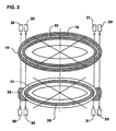
- Figure 2 shows, schematically, the alignment of certain components of device 10.
- device 10 includes a rotating disk 16 having a first track 18 and a second track 20.
- Each track 18, 20 is made up of alternating lines of high and low transparency, typically with a sinusoidal variation of transmissivity.
- Rotating disk 16 is rotated continuously about the axis of rotation of shaft 12.
- Aligned opposite first track 18 and parallel to rotating disk 16 are two optical grids 22, each having alternating lines of high and low transparency.
- Grids 22 are fixed relative to base 14, typically on opposite sides of the axis of rotation of shaft 12.
- a measuring disk 24, attached to shaft 12, is aligned coaxially with rotating disk 16.
- Measuring disk 24 has a track 26 of alternating lines of high and low transparency, aligned opposite second track 20 .
- Device 10 also features photoelectric sensors 28 and 30 which generate signals corresponding to variations in measured optical transmissivity.
- Photoelectric sensors 28 generate a reference signal corresponding to variations in optical transmissivity through a combination of first track 18 and optical grid 22.
- Photoelectric sensors 30 generate a measurement signal corresponding to variations in optical transmissivity through a combination of second track 20 and track 26.
- These signals are then processed by a processor 32 to calculate information relating to the precise angular position of shaft 12 relative to base 14.
- a processor 32 to calculate information relating to the precise angular position of shaft 12 relative to base 14.
- the arrangement of device 10 in relation to shaft 12 and base 14 is arbitrary. Hence, device 10 may readily be reversed such that measuring disk 24 is fixed to base 14, and optical grids 22 are attached shaft 12, without altering the functionality of device 10 .
- since only relative rotation between shaft 12 and base 14 is to be measured it is immaterial whether device 10 is arranged to measure rotation of shaft 12 relative to base 14, or of base 14 relative to shaft 12.
- Device 10 provides a major improvement over the prior art calibration systems by allowing highly precise angular measurement of 360 positions within a total time of 20-30 minutes, including set-up time. Device 10 also utilizes relatively low-precision components, thereby offering considerable cost savings over the prior art systems.
- rotating disk 16 and measuring disk 24 are typically made from similar materials, and produced by similar techniques, to those used for optical disks in conventional encoders.
- rotating disk 16 has a diameter of about 50 mm.
- Rotating disk 16 and measuring disk 24 are preferably mounted sufficiently close to prevent significant transmission of diffracted light. Typically the spacing between them is of the order of 0.1 mm.
- First track 18 and second track 20 of rotating disk 16 feature equal numbers of radial lines at a constant angular spacing.
- the lines of tracks 18 and 20 are in phase with each other, i.e., each line of first track 18 is collinear with one line of second track 20.
- tracks 18 and 20 may be implemented as a single broad track.
- First track 18 and second track 20 typically feature between about 1000 and about 10000 lines.
- a value of about 3600 lines i.e., an angular spacing of 0.1°, is sufficient to provide very high accuracy without requiring highly expensive production techniques.
- the lines are preferably opaque, or near-opaque, lines on a relatively transparent background, and are preferably sufficiently broad to cover about 50% of the functional area of each track.
- any arrangement of equally spaced radially-extending regions of relatively higher transparency alternating with equally spaced radially-extending regions of relatively lower transparency will be functional.
- the various options for the pattern of regions in tracks 18 and 20 will be referred to herein generally as alternating lines of high and low transparency.
- Rotating disk 16 is mounted on a rotating hub 34 which is driven continuously through a flexible coupling 35 by a motor 36.
- Motor 36 is preferably of a type which does not produce significant vibration. Coupling 35 prevents slight eccentricity of motor 36 from effecting alignment of rotating disk 16.
- the speed of rotation of motor 36 is not critical, but should be significantly greater than the anticipated speed of rotation of rotary table 1 3 .
- Motor 36 is attached to a casing 38 which provides a rigid structure and protective cover for device 10 .
- base 14 For the purposes of calibrating an existing rotary table 13, base 14 must be fixed to some rigid structure which provides a fixed relation to the basis of rotor table 13.
- one side of casing 38 is attached to base 14 though a ball-and-socket joint 40, and shaft 12 is rotatably mounted through bearings 42 in the opposite side of casing 38.
- This configuration allows convenient accommodation of different positions or attitudes of base 14 relative to rotary table 13 without interfering with operation of device 10.
- An additional flexible coupling 37 is provided between shaft 12 and rotary table 13 thereby making device 10 less sensitive to eccentric mounting of shaft 12 relative to rotary table 13.
- Measuring disk 24 is mounted near the end of shaft 12 parallel to rotating disk 16 and in a common plane with optical grids 22. Measuring disk 24 is generally equivalent to rotating disk 16 cut down such that its radius lies between that of first track 18 and second track 20.
- Track 26 features a number of lines equal to that of tracks 18 and 20.
- the lines of track 26 are preferably opaque, or near-opaque, lines on a relatively transparent background, and are preferably sufficiently broad to provide about 50% coverage of the operative area of track 26.
- One of optical grids 22 and one of each of photoelectric sensors 28 and 30 are typically set in a U-shaped bracket 46 attached to the inside of casing 38 such that it extends over the faces of rotating disk 16 and measuring disk 24 .
- a single U-shaped bracket 46 with a single set of one of optical grids 22 and one of each of photoelectric sensors 28 and 30, would be sufficient.
- two such assemblies are provided opposite to each other, i.e., one rotated from the other by 180° around the axis of rotation of shaft 12.
- the second pair of photoelectric sensors are designated, respectively, 29 and 31.
- the outputs from the two assemblies are processed by processor 32 to reduce the effects of cumulative error and shaft eccentricity. The details of this processing will be described below.
- Optical grids 22 are typically equivalent to a small section of first track 18 with its lines aligned towards the axis of rotation of shaft 12, i.e., "radially".
- the lines of optical grids 22 are "angularly spaced” at the same angular spacing as the lines of tracks 18, 20 and 26 relative to the axis of rotation of shaft 12 .
- the area of optical grids 22 is generally small in relation to the diameter of first track 18, the required pattern may be adequately approximated by a similar grid of equidistant parallel lines.
- Photoelectric sensors 28 and 30 each include a light emitter 48, such as, for example, an infrared LED or a bulb, and a light sensor 50 of any conventional type, such as, for example, a photodiode or phototransistor.
- a single light emitter 48 may be common to adjacent photoelectric sensors 28 and 30.
- photoelectric sensor 28 The two parts of photoelectric sensor 28 are in fixed alignment with optical grid 22 and aligned in a manner such that a beam of light from light emitter 48 passes through both optical grid 22 and first track 18 before reaching light sensor 50.
- Photoelectric sensor 28 thus produces an output signal, referred to herein as the "reference signal”, corresponding to the transmissivity of the superposition of optical grid 22 and first track 18 at any given instant.
- this reference signal is an oscillating signal.
- the output signals are typically of approximately sinusoidal form.
- photoelectric sensor 30 The two parts of photoelectric sensor 30 are aligned in a manner such that light from light emitter 48 passes through both second track 20 and track 26 of measuring disk 24 before reaching light sensor 50.
- Photoelectric sensor 30 thus produces an output signal, referred to herein as the "measuring signal", corresponding to the transmissivity of the superposition of track 26 and second track 20 at any given instant.
- This measuring signal is also an oscillating signal, differing only in phase from the reference signal, as will be explained below.
- the reference and measuring signals are transferred through electrical connections 52 to processor 32.
- the details of processor 32 will be described below with reference to Figures 6-7.
- Figure 3A shows, schematically, a portion of measuring disk 24 with track 26, and optical grid 22.
- measuring disk 24 is in a rotational position such that the lines of track 26 are out of alignment with the lines of optical grid 22 by about a quarter of the angular separation between the lines.
- Figure 3B shows, schematically, a portion of rotating disk 16 with first track 18 and second track 20, here broadened to form a single broad track 54 .
- the operative areas of photoelectric sensors 28 and 30 are indicated by dashed lines.
- Figure 4 illustrates the effect of superposing rotating disk 16 as shown in Figure 3B over measuring disk 24 and optical grid 22 as shown in Figure 3A.
- the rotation of rotating disk 16 causes the lines of tracks 18 and 20 to pass over the lines of optical grid 22 and track 26, respectively, thereby producing a cyclic variation of the amount of overlap of lines of low transparency over the operative areas of photoelectric sensors 28 and 30.
- This causes cyclic variation of the transmission measured by photoelectric sensors 28 and 30, generating oscillating output signals.
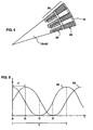
- Figure 5 shows the variations in the reference signal, designated 56 , produced by photoelectric sensor 28, and in the measuring signal, designated 58, produced by photoelectric sensor 30.
- the values corresponding to successive positions of rotating disk 16 are denoted by capitals A-D.
- the period of the oscillations measured, for example, from peak to peak is denoted T.
- the time lag of measuring signal 58 after reference signal 56 is denoted ⁇ t.
- phase shift ⁇ /2 ⁇ corresponds to the angular position of rotary table 13 within a 0.1° step, expressed as a fraction.
- device 10 transforms a rotation of 0.1° to a phase shift of 2 ⁇ , thereby providing much higher accuracy of angular measurement than is conventionally achieved using components of a given angular spacing or resolution.
- a single measurement of phase shift is sufficient to determine the angular position of rotary table 13 within a given rotation step, and the only additional information required is low-resolution information to determine within which rotation step the rotary table currently lies.
- extremely accurate measurement of angular position may be taken using low precision components. This is achieved by collecting large amounts of data in a manner such as to minimize systematic errors and then performing statistical analysis on the data, as will now be described with reference to Figures 6-7.
- Processor 32 typically includes a signal processor 60, a mode switch 62, a zero-crossing counter 64, a timer 66, a memory 68 and a microprocessor 70.
- Processor 32 typically also includes a display 72, a standard computer communications port 74 and a control panel or other input device 76.
- Signal processor 60 receives a pair of reference and measuring signals through electrical connections 52.
- Signal processor 60 generally converts the oscillatory reference and measuring signals to a pulse or square-wave form to allow use of digital processing techniques. For convenience, these wave forms will be referred to collectively as "pulse signal”. Devices and methods for performing this signal processing are well known in the art.
- signal processor 60 receives a pair of signals from each assembly, i.e., a total of four signals.
- signal processor also includes a switching system operative under the control of microprocessor 70 to select one pair of inputs. Typically, one pair of inputs remains in use continuously except for a short period when precise angular measurement is being made, as will be described below.
- Mode switch 62 sets the mode of processor 32 according to the state of shaft 12 as e ither rotating or stationary.
- mode switch 62 is automatic, functioning by identifying significant shifts in phase between the two signals.
- the sensitivity of mode switch 62 is set so as to disregard variations which are within the range of tolerance of the components used.
- mode switch 62 switches to pass the signals to phase shift zero-crossing counter 64 for coarse measurement of angular position.
- mode switch 62 switches to pass the signals to timer 66 for precise measurement of angular position.
- Signal processor 60 may provide somewhat different signal forms for of zero-crossing counter 64 and timer 66 as appropriate for the processing to be performed by each.
- mode switch 62 may be replaced by any other type of movement sensor or a simple manual switch operated by a user when precise measurement is required.
- Phase shift zero-crossing counter 64 maintains a cumulative count of zero crossings of the phase shift between the reference signal and the measuring signal. By way of example only, this may be done simply by counting pulses, i.e., adding one to a counter for each signal pulse which arrives and subtracting one for each reference pulse. The number reached then corresponds to the number of rotation steps moved through by shaft 12 relative to base 14 from some given initialization position. This number is passed on to microprocessor 70 for use in determining the overall angular position of rotary table 13.
- timer 66 this functions to derive a plurality of data pairs (T i , t i ) from the pulse signals corresponding to the reference and measuring signals.
- T i is the period of a cycle of the reference signal, i.e., the time between adjacent pulses or wave-fronts
- t i is the corresponding phase delay of the measuring signal relative to the reference signal, i.e., the time between the first of the adjacent pulses of the reference signal and the measuring signal pulse which follows it.
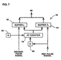
- timer 66 features a high-frequency counter 78 driven by a high frequency generator 80.
- generator 80 operates at a frequency of some tens of MHz, and preferably about 45 MHz.
- Counter 78 is typically a two-byte counter, but a larger counter may be used if required.
- a first buffer 82 is provided for measuring t i and a second buffer 84 is provided for measuring T i .
- Arrival of a pulse from the signal corresponding to the reference signal causes writing of the value from counter 78 to second buffer 84 and then, after a very short delay caused by delay 86, resetting of counter 78.
- the delay is solely for the purpose of allowing reading of the counter before resetting and is of the order of a nanosecond, thereby having no measurable effect on the precision of the device.
- a pulse from the signal corresponding to the measuring signal arrives, it causes writing of the value from counter 78 to first buffer 82, thereby recording t i , the number of generator cycles corresponding to the phase delay between the reference and measuring signals.
- Arrival of the subsequent reference signal pulse causes writing to second buffer 84 of the corresponding T i , the number of generator cycles corresponding to the period of the reference signal within which t i was measured.
- Counter 78 is then reset in preparation to measure the next data pair (T i+1 , t i+1 ) while (T i , t i ) is stored in memory 68.
- microprocessor 70 can then calculate a uniquely determined and highly accurate rotational position of rotary table 13 relative to base 14. This information may be displayed on display 72 and/or transferred directly to other equipment via communications port or interface 74.
- Control panel 76 may be used to control the mode of operation of the device as a whole, the format of the display, and any other parameters of the system which may be user-definable.
- signal processor 32 generally remains switched to a primary pair of reference and measured signals.
- mode switch 62 indicates that shaft 12 is rotating
- counter 64 tracks coarse movement of shaft 12 to determine within which rotational step it lies while timer 66 and memory 68 are bypassed.
- timer 66 starts automatically, or under control from control panel 76 via microprocessor 70, to take measurements of (T i , t i ) data pairs. This data is then accumulated in memory 68.
- processor 32 accumulates data pairs from consecutive cycles of the reference or measuring signals corresponding to a full rotation of rotating disk 16. This enables much more precise measurement than would otherwise be possible with components of a given tolerance since any systematic errors caused by irregularities of the disk tend to cancel out. Each data pair is used to calculate a position measurement and statistical analysis is performed on the results.
- microprocessor 70 actuates temporary switching of signal processor 60 to the signals from the second set of photoelectric sensors.
- Memory 68 then accumulates an additional set of data pairs corresponding to substantially a full rotation of rotating disk 16 .
- processor 32 utilizes 2N data pairs where N is the number of lines on each graduated disk. The total time for measurement and processing at each position is typically a few seconds corresponding to an almost-real-time measurement system.
Abstract
Description
- The present invention relates to measurement systems in general and in particular to a method for precise measurement of the angular position of a rotatable element.
- It is known to use rotary encoders to convert rotation of a shaft into periodic electrical signals. These signals are then processed to derive position information for display or as an input to control systems. Typically, rotary encoders produce the electrical signals by photoelectric scanning of a graduated disk.
- In high precision applications, i.e., where an angular resolution of ± 1 or 2 seconds of arc or less is required, the use of rotary encoders becomes problematic. For such applications, graduated discs having 36,000 lines or more are used, giving a cumulative error of several arcseconds. An example of such a system employing additional reference marks to improve accuracy is disclosed in U.S. Patent No. 4,477,189 to Ernst.
- High precision encoders are generally unsuitable for use in calibration of existing rotary tables since the whole encoder assembly is constructed from a complex arrangement of extremely high precision components built into a highly rigid structure. The extremely high precision components are also highly expensive.
- Calibration of high-precision rotary platforms or "rotary indexing tables" is typically performed using optical equipment such as a theodolite or a polygon collimator. Use of such equipment is extremely slow, generally requiring between 8 and 16 hours for set-up and calibration.
- In order to reduce calibration time, an automated calibration system based on angular interferometry of laser light has been developed. Such a system, disclosed in U.S. Patent No. 5,237,390 to Chaney, is available commercially as the RX10 system from Renishaw plc, U.K. However, even this very high-cost system typically requires 5-6 hours including the set-up time.
- There is therefore a need for an alternative method for precise measurement of the angular position of a rotatable element such as a rotary table. It would also be highly advantageous to have a device which used' low cost, relatively low-resolution components to make precise measurements of angular position.
- The present invention is of a method for measuring a precise angular position of an element rotatable relative to a base.
- US-A-3,702,471 (Shepherd Alexander Turnbull et al). discloses the features of the pre-characterizing feature of Claim 1 of the present application.
- There is provided, according to the teachings of the present invention, a method for performing precise measurement of the angular position of an element rotatable relative to a base, the method comprising the steps of: (a) generating a first signal in relation to relative movement between the base and a rotating member, the first signal being approximately periodic; (b) generating a second signal in relation to relative movement between the element and the rotating member, the second signal being approximately periodic;
characterized by (c) deriving from the first and second signals a plurality of data pairs (Ti, ti) where Ti is the period of a cycle of one of the first and second signals, and ti, is the corresponding phase delay between the first and second signals; (d) processing the plurality of data pairs to identify a precise representative phase difference between the first and second signals; and (e) calculating from the representative phase difference information relating to the precise angular position of the rotatable element relative to the base. - According to a further feature of the present invention, the first signal is generated by sensing light transmitted through a combination of a graduated scale associated with the base and a graduated track associated with the rotating member.
- According to a further feature of the present invention, the second signal is generated by sensing light transmitted through a combination of a first graduated track associated with the element and a second graduated track associated with the rotating member.
- According to a further feature of the present invention, the first and second signals include about 3600 cycles for each rotation of the rotating member.
- According to a further feature of the present invention, the step of deriving a plurality of data pairs (Ti, Ti) includes deriving the data pair for consecutive cycles of the first or second signal for N cycles, where N is equal to the number of cycles generated by each rotation of the rotating member.
- The invention is herein described, by way of example only, with reference to the accompanying drawings, wherein:
- FIG. 1 is a side cross-sectional view of a device, constructed and operative according to the teachings of the present invention, for measuring a precise angular position of an element rotatable relative to a base;
- FIG. 2 is a schematic exploded perspective view showing the alignment of components of the device of Figure 1;
- FIG. 3A is a schematic plan view of a part of a measuring disk and an optical grid from the device of Figure 1;
- FIG. 3B is a schematic plan view of a part of a rotating disk from the device of Figure 1;
- FIG. 4 is a schematic plan view showing the rotating disk of Figure 3B superposed over the measuring disk and optical grid of Figure 3A;
- FIG. 5 is a graph showing the variation of transmitted light intensity with time for a reference signal and a measuring signal generated by photoelectric sensors in the device of Figure 1;
- FIG. 6 is a block diagram of a processor for use in the device of Figure 1; and
- FIG. 7 is a detailed block diagram of an example of a timer for use in the processor of Figure 6.
-
- The present invention is of a device and a method for measuring a precise angular position of an element rotatable relative to a base.
- The principles and operation of devices and methods according to the present invention may be better understood with reference to the drawings and the accompanying description.
- Referring now to the drawings, Figure 1 shows a device, generally designated 10, constructed and operative according to the teachings of the present invention, for measuring a precise angular position of a
shaft 12 coupled to a rotary table 13 relative to abase 14. Figure 2 shows, schematically, the alignment of certain components ofdevice 10. - Generally speaking,
device 10 includes arotating disk 16 having afirst track 18 and asecond track 20. Eachtrack disk 16 is rotated continuously about the axis of rotation ofshaft 12. Aligned oppositefirst track 18 and parallel to rotatingdisk 16 are twooptical grids 22, each having alternating lines of high and low transparency.Grids 22 are fixed relative tobase 14, typically on opposite sides of the axis of rotation ofshaft 12. Ameasuring disk 24, attached toshaft 12, is aligned coaxially with rotatingdisk 16. Measuringdisk 24 has atrack 26 of alternating lines of high and low transparency, aligned oppositesecond track 20. -
Device 10 also featuresphotoelectric sensors Photoelectric sensors 28 generate a reference signal corresponding to variations in optical transmissivity through a combination offirst track 18 andoptical grid 22.Photoelectric sensors 30 generate a measurement signal corresponding to variations in optical transmissivity through a combination ofsecond track 20 andtrack 26. These signals are then processed by aprocessor 32 to calculate information relating to the precise angular position ofshaft 12 relative tobase 14. It should be noted that the arrangement ofdevice 10 in relation toshaft 12 andbase 14 is arbitrary. Hence,device 10 may readily be reversed such that measuringdisk 24 is fixed tobase 14, andoptical grids 22 are attachedshaft 12, without altering the functionality ofdevice 10. Similarly, since only relative rotation betweenshaft 12 andbase 14 is to be measured, it is immaterial whetherdevice 10 is arranged to measure rotation ofshaft 12 relative tobase 14, or ofbase 14 relative toshaft 12. -
Device 10 provides a major improvement over the prior art calibration systems by allowing highly precise angular measurement of 360 positions within a total time of 20-30 minutes, including set-up time.Device 10 also utilizes relatively low-precision components, thereby offering considerable cost savings over the prior art systems. - Turning now to the features of
device 10 in more detail, rotatingdisk 16 and measuringdisk 24 are typically made from similar materials, and produced by similar techniques, to those used for optical disks in conventional encoders. Typically, rotatingdisk 16 has a diameter of about 50 mm. Rotatingdisk 16 and measuringdisk 24 are preferably mounted sufficiently close to prevent significant transmission of diffracted light. Typically the spacing between them is of the order of 0.1 mm. -
First track 18 andsecond track 20 of rotatingdisk 16 feature equal numbers of radial lines at a constant angular spacing. The lines oftracks first track 18 is collinear with one line ofsecond track 20. In fact, depending on design considerations, tracks 18 and 20 may be implemented as a single broad track. -
First track 18 andsecond track 20 typically feature between about 1000 and about 10000 lines. Preferably, a value of about 3600 lines, i.e., an angular spacing of 0.1°, is sufficient to provide very high accuracy without requiring highly expensive production techniques. The lines are preferably opaque, or near-opaque, lines on a relatively transparent background, and are preferably sufficiently broad to cover about 50% of the functional area of each track. However, any arrangement of equally spaced radially-extending regions of relatively higher transparency alternating with equally spaced radially-extending regions of relatively lower transparency will be functional. Thus, the various options for the pattern of regions intracks -
Rotating disk 16 is mounted on a rotatinghub 34 which is driven continuously through aflexible coupling 35 by amotor 36.Motor 36 is preferably of a type which does not produce significant vibration.Coupling 35 prevents slight eccentricity ofmotor 36 from effecting alignment ofrotating disk 16. The speed of rotation ofmotor 36 is not critical, but should be significantly greater than the anticipated speed of rotation of rotary table 13.Motor 36 is attached to acasing 38 which provides a rigid structure and protective cover fordevice 10. - For the purposes of calibrating an existing rotary table 13,
base 14 must be fixed to some rigid structure which provides a fixed relation to the basis of rotor table 13. In the implementation shown here, one side ofcasing 38 is attached to base 14 though a ball-and-socket joint 40, andshaft 12 is rotatably mounted throughbearings 42 in the opposite side ofcasing 38. This configuration allows convenient accommodation of different positions or attitudes ofbase 14 relative to rotary table 13 without interfering with operation ofdevice 10. An additionalflexible coupling 37 is provided betweenshaft 12 and rotary table 13 thereby makingdevice 10 less sensitive to eccentric mounting ofshaft 12 relative to rotary table 13. - Measuring
disk 24 is mounted near the end ofshaft 12 parallel torotating disk 16 and in a common plane withoptical grids 22. Measuringdisk 24 is generally equivalent torotating disk 16 cut down such that its radius lies between that offirst track 18 andsecond track 20.Track 26 features a number of lines equal to that oftracks track 26 are preferably opaque, or near-opaque, lines on a relatively transparent background, and are preferably sufficiently broad to provide about 50% coverage of the operative area oftrack 26. - One of
optical grids 22 and one of each ofphotoelectric sensors U-shaped bracket 46 attached to the inside of casing 38 such that it extends over the faces ofrotating disk 16 and measuringdisk 24. In a basic embodiment of the present invention, a singleU-shaped bracket 46, with a single set of one ofoptical grids 22 and one of each ofphotoelectric sensors shaft 12. The second pair of photoelectric sensors are designated, respectively, 29 and 31. The outputs from the two assemblies are processed byprocessor 32 to reduce the effects of cumulative error and shaft eccentricity. The details of this processing will be described below. -
Optical grids 22 are typically equivalent to a small section offirst track 18 with its lines aligned towards the axis of rotation ofshaft 12, i.e., "radially". The lines ofoptical grids 22 are "angularly spaced" at the same angular spacing as the lines oftracks shaft 12. However, since the area ofoptical grids 22 is generally small in relation to the diameter offirst track 18, the required pattern may be adequately approximated by a similar grid of equidistant parallel lines. -
Photoelectric sensors light emitter 48, such as, for example, an infrared LED or a bulb, and alight sensor 50 of any conventional type, such as, for example, a photodiode or phototransistor. Asingle light emitter 48 may be common to adjacentphotoelectric sensors - The two parts of
photoelectric sensor 28 are in fixed alignment withoptical grid 22 and aligned in a manner such that a beam of light fromlight emitter 48 passes through bothoptical grid 22 andfirst track 18 before reachinglight sensor 50.Photoelectric sensor 28 thus produces an output signal, referred to herein as the "reference signal", corresponding to the transmissivity of the superposition ofoptical grid 22 andfirst track 18 at any given instant. As will be explained below, this reference signal is an oscillating signal. The output signals are typically of approximately sinusoidal form. - The two parts of
photoelectric sensor 30 are aligned in a manner such that light fromlight emitter 48 passes through bothsecond track 20 andtrack 26 of measuringdisk 24 before reachinglight sensor 50.Photoelectric sensor 30 thus produces an output signal, referred to herein as the "measuring signal", corresponding to the transmissivity of the superposition oftrack 26 andsecond track 20 at any given instant. This measuring signal is also an oscillating signal, differing only in phase from the reference signal, as will be explained below. - The reference and measuring signals are transferred through
electrical connections 52 toprocessor 32. The details ofprocessor 32 will be described below with reference to Figures 6-7. - Turning now to the operation of
device 10, this will be described with reference to Figures 3-5. Figure 3A shows, schematically, a portion of measuringdisk 24 withtrack 26, andoptical grid 22. In this example, measuringdisk 24 is in a rotational position such that the lines oftrack 26 are out of alignment with the lines ofoptical grid 22 by about a quarter of the angular separation between the lines. Figure 3B shows, schematically, a portion ofrotating disk 16 withfirst track 18 andsecond track 20, here broadened to form a singlebroad track 54. In both Figures 3A and 3B, the operative areas ofphotoelectric sensors - Figure 4 illustrates the effect of superposing
rotating disk 16 as shown in Figure 3B over measuringdisk 24 andoptical grid 22 as shown in Figure 3A. The rotation ofrotating disk 16 causes the lines oftracks optical grid 22 andtrack 26, respectively, thereby producing a cyclic variation of the amount of overlap of lines of low transparency over the operative areas ofphotoelectric sensors photoelectric sensors - Figure 5 shows the variations in the reference signal, designated 56, produced by
photoelectric sensor 28, and in the measuring signal, designated 58, produced byphotoelectric sensor 30. The values corresponding to successive positions ofrotating disk 16 are denoted by capitals A-D. The period of the oscillations measured, for example, from peak to peak is denoted T. The time lag of measuringsignal 58 afterreference signal 56 is denoted Δt. A normalized phase shift Δ between the signals is then defined by: - It will readily be appreciated that calculation of the normalized phase shift Δ determines extremely accurately the angular position of measuring
disk 24 relative tooptical grid 22, and hence ofshaft 12 and rotary table 13 relative tobase 14, within a certain rotation step. Expressed algebraically, if measuringtrack 26 has a total of N lines so that the angular step between them is given by Δ=360°/N, the angular position of rotary table 13 relative to base 14 measured from some arbitrary initialization position may be written as:optical grid 22 are ruled with lines at an angular spacing of Δ=0.1° (N =3600 lines per rotation), phase shift Δ/2π corresponds to the angular position of rotary table 13 within a 0.1° step, expressed as a fraction. Thus,device 10 transforms a rotation of 0.1° to a phase shift of 2π, thereby providing much higher accuracy of angular measurement than is conventionally achieved using components of a given angular spacing or resolution. - In principle, a single measurement of phase shift is sufficient to determine the angular position of rotary table 13 within a given rotation step, and the only additional information required is low-resolution information to determine within which rotation step the rotary table currently lies. However, it is a particular feature of a preferred embodiment of the present invention that extremely accurate measurement of angular position may be taken using low precision components. This is achieved by collecting large amounts of data in a manner such as to minimize systematic errors and then performing statistical analysis on the data, as will now be described with reference to Figures 6-7.
- Figure 6 shows a possible structure of
processor 32.Processor 32 typically includes asignal processor 60, amode switch 62, a zero-crossingcounter 64, atimer 66, amemory 68 and amicroprocessor 70.Processor 32 typically also includes adisplay 72, a standardcomputer communications port 74 and a control panel orother input device 76. -
Signal processor 60 receives a pair of reference and measuring signals throughelectrical connections 52.Signal processor 60 generally converts the oscillatory reference and measuring signals to a pulse or square-wave form to allow use of digital processing techniques. For convenience, these wave forms will be referred to collectively as "pulse signal". Devices and methods for performing this signal processing are well known in the art. In a preferred embodiment in which two photoelectric sensor assemblies are used,signal processor 60 receives a pair of signals from each assembly, i.e., a total of four signals. In this case, signal processor also includes a switching system operative under the control ofmicroprocessor 70 to select one pair of inputs. Typically, one pair of inputs remains in use continuously except for a short period when precise angular measurement is being made, as will be described below. - From
signal processor 60, two pulse signals corresponding to a pair of reference and measuring signals are transferred tomode switch 62.Mode switch 62 sets the mode ofprocessor 32 according to the state ofshaft 12 as either rotating or stationary. Preferably,mode switch 62 is automatic, functioning by identifying significant shifts in phase between the two signals. The sensitivity ofmode switch 62 is set so as to disregard variations which are within the range of tolerance of the components used. Whenshaft 12 is rotating,mode switch 62 switches to pass the signals to phase shift zero-crossingcounter 64 for coarse measurement of angular position. Whenshaft 12 is stationary,mode switch 62 switches to pass the signals totimer 66 for precise measurement of angular position.Signal processor 60, may provide somewhat different signal forms for of zero-crossingcounter 64 andtimer 66 as appropriate for the processing to be performed by each. Alternatively,mode switch 62 may be replaced by any other type of movement sensor or a simple manual switch operated by a user when precise measurement is required. - Phase shift zero-crossing
counter 64 maintains a cumulative count of zero crossings of the phase shift between the reference signal and the measuring signal. By way of example only, this may be done simply by counting pulses, i.e., adding one to a counter for each signal pulse which arrives and subtracting one for each reference pulse. The number reached then corresponds to the number of rotation steps moved through byshaft 12 relative to base 14 from some given initialization position. This number is passed on tomicroprocessor 70 for use in determining the overall angular position of rotary table 13. - Turning now to
timer 66, this functions to derive a plurality of data pairs (Ti, ti) from the pulse signals corresponding to the reference and measuring signals. Within each data pair, Ti is the period of a cycle of the reference signal, i.e., the time between adjacent pulses or wave-fronts, and ti is the corresponding phase delay of the measuring signal relative to the reference signal, i.e., the time between the first of the adjacent pulses of the reference signal and the measuring signal pulse which follows it. - An example of a structure for
timer 66 is shown in Figure 7. Thus, according to this example,timer 66 features a high-frequency counter 78 driven by ahigh frequency generator 80. Typically,generator 80 operates at a frequency of some tens of MHz, and preferably about 45 MHz.Counter 78 is typically a two-byte counter, but a larger counter may be used if required. Afirst buffer 82 is provided for measuring ti and asecond buffer 84 is provided for measuring Ti. - Arrival of a pulse from the signal corresponding to the reference signal causes writing of the value from counter 78 to
second buffer 84 and then, after a very short delay caused bydelay 86, resetting ofcounter 78. The delay is solely for the purpose of allowing reading of the counter before resetting and is of the order of a nanosecond, thereby having no measurable effect on the precision of the device. When a pulse from the signal corresponding to the measuring signal arrives, it causes writing of the value from counter 78 tofirst buffer 82, thereby recording ti, the number of generator cycles corresponding to the phase delay between the reference and measuring signals. Arrival of the subsequent reference signal pulse causes writing tosecond buffer 84 of the corresponding Ti, the number of generator cycles corresponding to the period of the reference signal within which ti was measured.Counter 78 is then reset in preparation to measure the next data pair (Ti+1, ti+1) while (Ti, ti) is stored inmemory 68. -
Microprocessor 70 then processes the data pairs stored inmemory 68 to identify a precise representative phase difference between the reference signal and the measuring signal. This is typically done by calculating the normalized phase difference: - Parenthetically, it is of interest to note that, since the quantity of interest is the normalized or relative phase difference, i.e., the ratio of ti to Ti, the period of the oscillations T may vary without affecting the accuracy of measurements. Thus, as mentioned above, neither the particular speed of rotation of
motor 36, nor its constancy, is critical. - Based on the precise representative phase difference together with the reading from zero-crossing
counter 64,microprocessor 70 can then calculate a uniquely determined and highly accurate rotational position of rotary table 13 relative tobase 14. This information may be displayed ondisplay 72 and/or transferred directly to other equipment via communications port orinterface 74.Control panel 76 may be used to control the mode of operation of the device as a whole, the format of the display, and any other parameters of the system which may be user-definable. - Turning now to the operation of
processor 32, as mentioned earlier, signal processor generally remains switched to a primary pair of reference and measured signals. As long asmode switch 62 indicates thatshaft 12 is rotating, counter 64 tracks coarse movement ofshaft 12 to determine within which rotational step it lies whiletimer 66 andmemory 68 are bypassed. Whenshaft 12 stops,timer 66 starts automatically, or under control fromcontrol panel 76 viamicroprocessor 70, to take measurements of (Ti, ti) data pairs. This data is then accumulated inmemory 68. - It is a particular feature of a preferred embodiment of the present invention that
processor 32 accumulates data pairs from consecutive cycles of the reference or measuring signals corresponding to a full rotation ofrotating disk 16. This enables much more precise measurement than would otherwise be possible with components of a given tolerance since any systematic errors caused by irregularities of the disk tend to cancel out. Each data pair is used to calculate a position measurement and statistical analysis is performed on the results. - As a further technique for reducing systematic errors, after collection of data pairs corresponding to a rotation of
rotating disk 16 using signals from one set of photoelectric sensors,microprocessor 70 actuates temporary switching ofsignal processor 60 to the signals from the second set of photoelectric sensors.Memory 68 then accumulates an additional set of data pairs corresponding to substantially a full rotation ofrotating disk 16. In this way,processor 32 utilizes 2N data pairs where N is the number of lines on each graduated disk. The total time for measurement and processing at each position is typically a few seconds corresponding to an almost-real-time measurement system. - If required, the measuring cycle may be repeated one or more times, thereby providing multiples of 2N (2kN: k=1,2,3...). Since this corresponds to a very large number of measurements taken in a manner minimizing systematic errors, statistical analysis yields a very high degree of precision.
- In a preferred example in which rotating
disk 16 features about 3600 lines per rotation, use of a single full set of data pairs from each set of photoelectric sensors yields 7200 data pairs. Analysis of this data provides angular precision of better than ½ arcsecond, thereby representing a profound improvement over the precision achieved with components of similar tolerances in the prior art. - It will be appreciated that the above descriptions are intended only to serve as examples, and that many other embodiments are possible within the scope of the present invention which is solely defined by the appended claims. For example, while the present invention has been described in an embodiment particularly suited to calibration of existing rotary tables or platforms, it may readily be adapted for inclusion in a rotary platform assembly to be used as part of the control system.
Claims (5)
- A method for performing precise measurement of the angular position of an element (12, 13) rotatable relative to a base (14), the method comprising the steps of:(a) generating a first signal (56) in relation to relative movement between the base (14) and a rotating member (16), said first signal being approximately periodic;(b) generating a second signal (58) in relation to relative movement between the element (12, 13) and said rotating member (16), said second signal being approximately periodic;
characterized by:(c) deriving from said first and second signals (56, 58) a plurality of data pairs (Ti, ti), where Ti is the period of a cycle of one of said first and second signals, and ti is the corresponding phase delay between said first and second signals;(d) processing said plurality of data pairs to identify a precise representative phase difference between said first and second signals; and(e) calculating from said representative phase difference information relating to the precise angular position of the rotatable element relative to the base. - A method as in claim 1, wherein said first signal (56) is generated by sensing light transmitted through a combination of a graduated scale (22) associated with said base and a graduated track (18) associated with said rotating member (16).
- A method as in claim 1, wherein said second signal (58) is generated by sensing light transmitted through a combination of a first graduated track (26) associated with said element and a second graduated track (20) associated with said rotating member (16).
- A method as in claim 1, wherein said first and second signals (56, 58) include about 3600 cycles for each rotation of said rotating member.
- A method as in claim 1, wherein said step of deriving a plurality of data pairs (Ti, ti) includes deriving said data pair for consecutive cycles of said first or second signal for N cycles, where N is equal to the number of cycles generated by each rotation of said rotating member.
Applications Claiming Priority (3)
| Application Number | Priority Date | Filing Date | Title |
|---|---|---|---|
| US08/627,200 US5698851A (en) | 1996-04-03 | 1996-04-03 | Device and method for precise angular measurement by mapping small rotations into large phase shifts |
| US627200 | 1996-04-03 | ||
| PCT/US1997/005393 WO1997037368A1 (en) | 1996-04-03 | 1997-04-01 | Angular measurement apparatus |
Publications (3)
| Publication Number | Publication Date |
|---|---|
| EP0892982A1 EP0892982A1 (en) | 1999-01-27 |
| EP0892982A4 EP0892982A4 (en) | 2001-03-21 |
| EP0892982B1 true EP0892982B1 (en) | 2005-06-29 |
Family
ID=24513654
Family Applications (1)
| Application Number | Title | Priority Date | Filing Date |
|---|---|---|---|
| EP97917787A Expired - Lifetime EP0892982B1 (en) | 1996-04-03 | 1997-04-01 | Angular measurement apparatus |
Country Status (9)
| Country | Link |
|---|---|
| US (1) | US5698851A (en) |
| EP (1) | EP0892982B1 (en) |
| JP (1) | JP2000507703A (en) |
| KR (1) | KR20000005250A (en) |
| AT (1) | ATE298883T1 (en) |
| AU (1) | AU2602697A (en) |
| DE (1) | DE69733647T2 (en) |
| IL (1) | IL126213A (en) |
| WO (1) | WO1997037368A1 (en) |
Families Citing this family (8)
| Publication number | Priority date | Publication date | Assignee | Title |
|---|---|---|---|---|
| WO1995033180A1 (en) * | 1994-06-01 | 1995-12-07 | Stridsberg Innovation Ab | Position transducer |
| GB2340234B (en) * | 1996-03-08 | 2000-09-06 | Kawasaki Heavy Ind Ltd | Modular encoder and method for manufacturing the same |
| GB9914918D0 (en) * | 1999-06-26 | 1999-08-25 | British Aerospace | Method and apparatus for calibrating a first co-ordinate frame of an indexing means in a second frame of a sensing means |
| US7199354B2 (en) * | 2004-08-26 | 2007-04-03 | Dr. Johannes Heidenhain Gmbh | Detector array for optical encoders |
| US7244928B2 (en) * | 2005-01-07 | 2007-07-17 | Avago Technologies Ecbu Ip (Singapore) Pte. Ltd. | Optical encoder |
| DE102006027733A1 (en) * | 2006-06-16 | 2007-12-20 | Daimlerchrysler Ag | Electrical sensor e.g. water level sensor, for use in e.g. lorry, has interface unit outputting maintenance or operating condition information, where sensor-integrated display unit displays maintenance or operating condition information |
| WO2009103342A1 (en) | 2008-02-22 | 2009-08-27 | Trimble Jena Gmbh | Angle measurement device and method |
| CN114966087A (en) * | 2022-05-12 | 2022-08-30 | 中国科学院西安光学精密机械研究所 | Wide-application-range testing device for tracking angular velocity of photoelectric tracking instrument |
Family Cites Families (10)
| Publication number | Priority date | Publication date | Assignee | Title |
|---|---|---|---|---|
| GB1284641A (en) * | 1970-01-08 | 1972-08-09 | Ferranti Ltd | Improvements relating to measuring apparatus |
| JPS5971598A (en) * | 1982-10-18 | 1984-04-23 | フアナツク株式会社 | Optical absolute encoder |
| DE3311204A1 (en) * | 1983-03-26 | 1984-10-04 | Dr. Johannes Heidenhain Gmbh, 8225 Traunreut | INCREMENTAL LENGTH OR ANGLE MEASURING DEVICE |
| DE3412063A1 (en) * | 1984-03-31 | 1985-11-28 | Dr. Johannes Heidenhain Gmbh, 8225 Traunreut | POSITION MEASURING DEVICE |
| DE3429648A1 (en) * | 1984-08-11 | 1986-02-13 | Dr. Johannes Heidenhain Gmbh, 8225 Traunreut | POSITION MEASURING DEVICE |
| JPS63281015A (en) * | 1987-05-13 | 1988-11-17 | Matsushita Electric Ind Co Ltd | Reference signal generating device for position detector |
| JP2893194B2 (en) * | 1990-01-09 | 1999-05-17 | 株式会社小野測器 | Rotational angular displacement detector |
| JP2930683B2 (en) * | 1990-08-23 | 1999-08-03 | マツダ株式会社 | Torque detector |
| JPH0634462A (en) * | 1992-07-20 | 1994-02-08 | Suzuki Motor Corp | Torque detecting device |
| JP3208933B2 (en) * | 1993-06-01 | 2001-09-17 | 株式会社ニコン | Position measuring device |
-
1996
- 1996-04-03 US US08/627,200 patent/US5698851A/en not_active Expired - Lifetime
-
1997
- 1997-04-01 JP JP9535557A patent/JP2000507703A/en active Pending
- 1997-04-01 DE DE69733647T patent/DE69733647T2/en not_active Expired - Fee Related
- 1997-04-01 EP EP97917787A patent/EP0892982B1/en not_active Expired - Lifetime
- 1997-04-01 KR KR1019980707939A patent/KR20000005250A/en not_active Application Discontinuation
- 1997-04-01 IL IL12621397A patent/IL126213A/en not_active IP Right Cessation
- 1997-04-01 AU AU26026/97A patent/AU2602697A/en not_active Abandoned
- 1997-04-01 AT AT97917787T patent/ATE298883T1/en not_active IP Right Cessation
- 1997-04-01 WO PCT/US1997/005393 patent/WO1997037368A1/en active IP Right Grant
Also Published As
| Publication number | Publication date |
|---|---|
| US5698851A (en) | 1997-12-16 |
| ATE298883T1 (en) | 2005-07-15 |
| IL126213A (en) | 2000-02-29 |
| DE69733647T2 (en) | 2006-04-27 |
| WO1997037368A1 (en) | 1997-10-09 |
| EP0892982A4 (en) | 2001-03-21 |
| JP2000507703A (en) | 2000-06-20 |
| EP0892982A1 (en) | 1999-01-27 |
| KR20000005250A (en) | 2000-01-25 |
| DE69733647D1 (en) | 2005-08-04 |
| IL126213A0 (en) | 1999-05-09 |
| AU2602697A (en) | 1997-10-22 |
Similar Documents
| Publication | Publication Date | Title |
|---|---|---|
| US8093915B2 (en) | Angle-measuring device with an absolute-type disk capacitive sensor | |
| JP5356979B2 (en) | Position measuring apparatus and operation method of position measuring apparatus | |
| US4218615A (en) | Incremental digital shaft encoder | |
| JP2009294073A (en) | Absolute encoder | |
| JPH05500707A (en) | High resolution absolute encoder | |
| EP0892982B1 (en) | Angular measurement apparatus | |
| JP2000241157A (en) | Angle measuring system | |
| JPH08178700A (en) | Incremental encoder | |
| Portman et al. | Phase-statistical method and device for high precise and high-efficiency angular measurements | |
| JPH09145408A (en) | Encoder device | |
| JP4768164B2 (en) | Rotary encoder device | |
| JPS607316A (en) | Angle measuring device | |
| JP3080375B2 (en) | Incremental encoder | |
| JPH0462003B2 (en) | ||
| JPS61212728A (en) | Rotary encoder | |
| JPH045142B2 (en) | ||
| US6946648B2 (en) | Opto-electronic device for angle generation of ultrasonic probe | |
| JPH0462002B2 (en) | ||
| SU781875A1 (en) | Method of testing shaft angular position-to-code converters | |
| JPH0424645B2 (en) | ||
| JPH0326326B2 (en) | ||
| JPH0642942A (en) | Apparatus for measuring angle of rotation | |
| JPS60237317A (en) | Displacement converter | |
| SU1005126A1 (en) | Device for measuring excentricity of angle-to-code converter code scale | |
| SU1170289A1 (en) | Photometer |
Legal Events
| Date | Code | Title | Description |
|---|---|---|---|
| PUAI | Public reference made under article 153(3) epc to a published international application that has entered the european phase |
Free format text: ORIGINAL CODE: 0009012 |
|
| 17P | Request for examination filed |
Effective date: 19981103 |
|
| AK | Designated contracting states |
Kind code of ref document: A1 Designated state(s): AT CH DE ES FR GB IT LI SE |
|
| A4 | Supplementary search report drawn up and despatched |
Effective date: 20010201 |
|
| AK | Designated contracting states |
Kind code of ref document: A4 Designated state(s): AT CH DE ES FR GB IT LI SE |
|
| RIC1 | Information provided on ipc code assigned before grant |
Free format text: 7G 01D 5/347 A, 7G 01D 5/244 B, 7H 01J 5/16 B, 7G 01D 5/34 B |
|
| 17Q | First examination report despatched |
Effective date: 20031118 |
|
| GRAP | Despatch of communication of intention to grant a patent |
Free format text: ORIGINAL CODE: EPIDOSNIGR1 |
|
| GRAS | Grant fee paid |
Free format text: ORIGINAL CODE: EPIDOSNIGR3 |
|
| GRAA | (expected) grant |
Free format text: ORIGINAL CODE: 0009210 |
|
| AK | Designated contracting states |
Kind code of ref document: B1 Designated state(s): AT CH DE ES FR GB IT LI SE |
|
| PG25 | Lapsed in a contracting state [announced via postgrant information from national office to epo] |
Ref country code: LI Free format text: LAPSE BECAUSE OF FAILURE TO SUBMIT A TRANSLATION OF THE DESCRIPTION OR TO PAY THE FEE WITHIN THE PRESCRIBED TIME-LIMIT Effective date: 20050629 Ref country code: IT Free format text: LAPSE BECAUSE OF FAILURE TO SUBMIT A TRANSLATION OF THE DESCRIPTION OR TO PAY THE FEE WITHIN THE PRESCRIBED TIME-LIMIT;WARNING: LAPSES OF ITALIAN PATENTS WITH EFFECTIVE DATE BEFORE 2007 MAY HAVE OCCURRED AT ANY TIME BEFORE 2007. THE CORRECT EFFECTIVE DATE MAY BE DIFFERENT FROM THE ONE RECORDED. Effective date: 20050629 Ref country code: CH Free format text: LAPSE BECAUSE OF FAILURE TO SUBMIT A TRANSLATION OF THE DESCRIPTION OR TO PAY THE FEE WITHIN THE PRESCRIBED TIME-LIMIT Effective date: 20050629 Ref country code: AT Free format text: LAPSE BECAUSE OF FAILURE TO SUBMIT A TRANSLATION OF THE DESCRIPTION OR TO PAY THE FEE WITHIN THE PRESCRIBED TIME-LIMIT Effective date: 20050629 |
|
| REG | Reference to a national code |
Ref country code: GB Ref legal event code: FG4D |
|
| REG | Reference to a national code |
Ref country code: CH Ref legal event code: EP |
|
| REF | Corresponds to: |
Ref document number: 69733647 Country of ref document: DE Date of ref document: 20050804 Kind code of ref document: P |
|
| PG25 | Lapsed in a contracting state [announced via postgrant information from national office to epo] |
Ref country code: SE Free format text: LAPSE BECAUSE OF FAILURE TO SUBMIT A TRANSLATION OF THE DESCRIPTION OR TO PAY THE FEE WITHIN THE PRESCRIBED TIME-LIMIT Effective date: 20050929 |
|
| PG25 | Lapsed in a contracting state [announced via postgrant information from national office to epo] |
Ref country code: ES Free format text: LAPSE BECAUSE OF FAILURE TO SUBMIT A TRANSLATION OF THE DESCRIPTION OR TO PAY THE FEE WITHIN THE PRESCRIBED TIME-LIMIT Effective date: 20051010 |
|
| REG | Reference to a national code |
Ref country code: CH Ref legal event code: PL |
|
| ET | Fr: translation filed | ||
| PLBE | No opposition filed within time limit |
Free format text: ORIGINAL CODE: 0009261 |
|
| STAA | Information on the status of an ep patent application or granted ep patent |
Free format text: STATUS: NO OPPOSITION FILED WITHIN TIME LIMIT |
|
| 26N | No opposition filed |
Effective date: 20060330 |
|
| PGFP | Annual fee paid to national office [announced via postgrant information from national office to epo] |
Ref country code: DE Payment date: 20090525 Year of fee payment: 13 |
|
| PGFP | Annual fee paid to national office [announced via postgrant information from national office to epo] |
Ref country code: GB Payment date: 20090930 Year of fee payment: 13 |
|
| PGFP | Annual fee paid to national office [announced via postgrant information from national office to epo] |
Ref country code: FR Payment date: 20091023 Year of fee payment: 13 |
|
| GBPC | Gb: european patent ceased through non-payment of renewal fee |
Effective date: 20100401 |
|
| REG | Reference to a national code |
Ref country code: FR Ref legal event code: ST Effective date: 20101230 |
|
| PG25 | Lapsed in a contracting state [announced via postgrant information from national office to epo] |
Ref country code: DE Free format text: LAPSE BECAUSE OF NON-PAYMENT OF DUE FEES Effective date: 20101103 |
|
| PG25 | Lapsed in a contracting state [announced via postgrant information from national office to epo] |
Ref country code: GB Free format text: LAPSE BECAUSE OF NON-PAYMENT OF DUE FEES Effective date: 20100401 |
|
| PG25 | Lapsed in a contracting state [announced via postgrant information from national office to epo] |
Ref country code: FR Free format text: LAPSE BECAUSE OF NON-PAYMENT OF DUE FEES Effective date: 20100430 |