EP0892188A1 - Kupplungsausrücklager mit angesetzter Anschlagsdruckplatte - Google Patents
Kupplungsausrücklager mit angesetzter Anschlagsdruckplatte Download PDFInfo
- Publication number
- EP0892188A1 EP0892188A1 EP98401729A EP98401729A EP0892188A1 EP 0892188 A1 EP0892188 A1 EP 0892188A1 EP 98401729 A EP98401729 A EP 98401729A EP 98401729 A EP98401729 A EP 98401729A EP 0892188 A1 EP0892188 A1 EP 0892188A1
- Authority
- EP
- European Patent Office
- Prior art keywords
- rotating ring
- flange
- bearing
- diaphragm
- connecting member
- Prior art date
- Legal status (The legal status is an assumption and is not a legal conclusion. Google has not performed a legal analysis and makes no representation as to the accuracy of the status listed.)
- Granted
Links
- 230000000295 complement effect Effects 0.000 claims abstract description 3
- 239000002184 metal Substances 0.000 claims description 11
- 230000014759 maintenance of location Effects 0.000 claims description 2
- 239000011324 bead Substances 0.000 description 6
- 238000005096 rolling process Methods 0.000 description 4
- 238000007789 sealing Methods 0.000 description 4
- 238000004519 manufacturing process Methods 0.000 description 3
- 238000005520 cutting process Methods 0.000 description 2
- 239000007787 solid Substances 0.000 description 2
- 230000006978 adaptation Effects 0.000 description 1
- 238000006073 displacement reaction Methods 0.000 description 1
- 238000010438 heat treatment Methods 0.000 description 1
- 238000012423 maintenance Methods 0.000 description 1
- 238000007726 management method Methods 0.000 description 1
- 210000000056 organ Anatomy 0.000 description 1
- 238000003860 storage Methods 0.000 description 1
- 229920002994 synthetic fiber Polymers 0.000 description 1
- 210000002105 tongue Anatomy 0.000 description 1
Images


Classifications
-
- F—MECHANICAL ENGINEERING; LIGHTING; HEATING; WEAPONS; BLASTING
- F16—ENGINEERING ELEMENTS AND UNITS; GENERAL MEASURES FOR PRODUCING AND MAINTAINING EFFECTIVE FUNCTIONING OF MACHINES OR INSTALLATIONS; THERMAL INSULATION IN GENERAL
- F16D—COUPLINGS FOR TRANSMITTING ROTATION; CLUTCHES; BRAKES
- F16D23/00—Details of mechanically-actuated clutches not specific for one distinct type
- F16D23/12—Mechanical clutch-actuating mechanisms arranged outside the clutch as such
- F16D23/14—Clutch-actuating sleeves or bearings; Actuating members directly connected to clutch-actuating sleeves or bearings
- F16D23/143—Arrangements or details for the connection between the release bearing and the diaphragm
- F16D23/144—With a disengaging thrust-ring distinct from the release bearing, and secured to the diaphragm
- F16D23/146—Arrangements for the connection between the thrust-ring and the release bearing
Definitions
- the present invention relates to the field of stops for clutch intended to act on the diaphragm of a clutch, in particular for a motor vehicle.
- the invention applies to clutch release bearings comprising a bearing of which one of the rings is rotating and the other ring is fixed.
- a self-centering element is generally interposed between the fixed ring of the bearing and the element of maneuver, said self-centering element ensuring the connection between these two parts while allowing, by its elasticity, a relative radial displacement between said two pieces.
- the bearing thus actuates the clutch via of its rotating ring according to an action diameter defined by the contact area between diaphragm and rotating ring of the bearing stop, whether solid or sheet metal.
- the tips of the fingers of diaphragm in contact with the rotating ring of the stopper may have a flat or well rounded shape and the corresponding contact surface of the rotating ring can also be rounded or planar.
- the thrust bearing can self-center in operation on the diaphragm thanks to the self-centering element and an existing radial clearance between the operating member and the fixed ring of the thrust bearing.
- the attack surface of a given stop therefore has a useful action diameter which is specific to it and is generally not suitable to operate with clutches different from each other, either by their action diameter, either by the shape of the finger tips of diaphragm. It is therefore necessary to have rotating stop rings adapted to each series of clutch action diameters and also to the shape of diaphragm finger tips. This leads to a multiplication production variants of the release bearings and an increase manufacturing, management and storage costs.
- the present invention aims to solve the problems of devices described above by proposing a simple thrust bearing and economical with sheet metal rings.
- the clutch release device is of the type comprising a rolling bearing fitted with a non-rotating ring and a rotating ring made of sheet metal, said device being capable act on a clutch mechanism diaphragm.
- the clutch release bearing device includes a flange Attached to the rotating ring, and intended to come into contact with the diaphragm.
- An economical clutch release bearing is thus obtained, fitted with a standard bearing and capable of adapting to different types clutch diaphragms.
- the attack flange is made of sheet metal.
- the collar drive is provided with centering means on the rotating ring, in the purpose of facilitating its assembly and guaranteeing the precision of its positioning.
- the centering means can comprise at least one flap capable of cooperating with a complementary surface of the ring rotating.
- the collar of attack comprises an internal face in abutment on the rotating ring and a external face opposite to the internal face and intended to come into contact with the diaphragm.
- the declutching stop device comprises elastic means for retaining the leading flange on the ring rotating, for example in the form of an axially connecting member elastic.
- the link member may include a plurality of legs extending axially around the rotating ring and provided with windows, the leading flange comprising radial protuberances forming hooks capable of cooperating with said windows.
- the tabs can extend axially in the bore of the ring rotating, adjacent to said bore.
- the legs can be axially elastic.
- the link member includes a circular base in the shape of a washer and bearing on the rotating ring axially opposite the drive flange.
- the base can be provided with circumferential undulations ensuring a some axial elasticity.
- This provides a thrust bearing with sheet metal rings, low weight, standardized manufacturing and provided with a flange attack allowing its adaptation to different types of diaphragm clutch.
- the clutch release bearing includes a rolling bearing 1 mounted on an operating element 2 at by means of a self-centering member 3.
- the operating element 2 is mounted on a guide tube 4 and comprises a tubular part 2a and a part radial 2b made of synthetic material overmolded on a plate of wear 6 adjacent to the radial part 2b and intended to come into contact with fork fingers 5.
- the bearing 1 is disposed on the side of the radial part 2b of the operating element 2 opposite the anti-wear plate 6.
- the bearing 1 includes a fixed inner ring 7, a rotating outer ring 8, made of stamped sheet metal, a row of rolling elements 9 maintained by a cage 10 and disposed between the inner 7 and outer 8 rings.
- fixed inner ring 7 is provided with a radial portion 7a (FIG. 3) which comes into contact with the radial portion 2b of the operating element 2.
- the self-centering member 3 is disposed in the bore of the ring inner 7 and includes a plurality of teeth 11 which are radially flexible and extending towards the tubular portion 2a of the element maneuver 2.
- the bearing 1 can therefore self-center with respect to the operating element 2 by causing the teeth 11 to flex the self-centering member 3.
- a sealing lip 12 coming from the member self-centering 3 extends axially outwards and rubs against the rotating outer ring 8.
- a sealing member 13 is also provided at the other end of bearing 1.
- the rotating outer ring 8 comprises a tubular portion 8a adjacent to the runway 8b provided for the row of elements wheels 9, and to the sealing member 13. On the side axially opposite to the operating element 2, the outer ring 8 comprises a portion radial 8c extending inward.
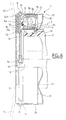
- the radial portion 8c is covered by a leading flange 14, made of stamped sheet metal, and comprising a radial portion 14a applying against the radial portion 8c of the outer ring 8, a continuous flap 14b surrounding the free end of the radial portion 8c of the outer ring 8, a protruding bead 14c axially outwardly disposed at the large diameter end of the radial portion 14a, and forming a contact surface with the fingers 15 ( Figure 3) of a clutch diaphragm.
- the fingers 15 are flat and the bead 14c is shaped rounded for good cooperation between these two elements.
- the leading flange 14 extends beyond the bead 14c by a axial portion 14d and by four radial protuberances forming hooks 16 slightly oriented axially opposite the element 2.
- the axial flap 14b and the axial portion 14d give the flange attack 14 great rigidity.
- the centering on the ring 8 can be do by one or the other of these axial portions.
- the hooks 16 come from the outer axial portion 14d by cutting and folding.
- a connecting member 17 made of thin sheet metal is provided around the outer ring 8.
- the connecting member 17 comprises four axial tabs 18, the free end of which is provided with a window 19 in which a hook protrudes 16.
- the other end of the connecting member 17 comprises a radial portion 20 forming a base directed inwards by relative to the legs 18 and provided with a plurality of corrugations 21 coming in axial support on the sealing member 13 of the bearing 1.
- the connecting member 17 ensures the elastic axial retention of the leading flange 14 relative to the outer ring 8 of the bearing 1.
- the leading flange 14 is centered relative to the outer ring 8 thanks to the flap 14b.
- the assembly is carried out by axially bringing the drive collar 14 and the connecting member 17, the outer ring 8 finding between these two elements.
- the bead 14c of the leading flange 14 is provided at the large diameter end of the radial portion 14a.
- a bead 14c in another position for example in the middle of the portion radial 14a or at its end of small diameter near the flap 14b. It is thus possible to use a bearing 1 of standard type whatever the type clutch diaphragm used and for a wide range of dimensions.
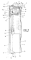
- FIG. 6 is illustrated a variant in which the bead of the leading flange 14 is deleted.
- Diaphragm fingers 15 clutch are cambered towards the leading flange 14.
- the attack flange 14 is provided with a bearing surface 14e on its radial portion 14a.
- the internal free end of the leading flange 14 is slightly bent inward as is the free end of the radial portion 8c.
- the operating element 2 is provided with a shoulder 2c in contact with the radial portion 7a of the inner ring 7 directed towards the inside.
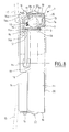
- FIG. 7 The variant illustrated in FIG. 7 is close to the previous one, at except that the legs 18 of the connecting member 17 are provided at their free end, of an oblique portion 18a, flared towards the outside, which allows the use of a support flange 14 of large diameter relative to to the diameter of the thrust bearing 1.
- the flange 14 is identical to that of FIG. 5.
- the legs 18 of the connecting member 17 are provided with corrugations 22. imparting axial elasticity.
- the base 20 is radial and devoid ripples. However, it could include it, as a variant.
- the operating element 2 is provided with a flange radial 2b disposed at the free end of the tubular part 2a.
- the organ self-centering 3 is in the form of a biconical washer whose the ends are cut into tongues 3a and 3b respectively support on a shoulder 2c and on a radial return 23a of the ring fixed outer 23, said return being thus maintained in permanent axial support against the radial flange 2b.
- the inner rotating ring 24 is extends outwards by a radial portion 24a which receives the flange 14.
- the collar 14 includes a radial portion 14a, a flange axial 14d surrounding said radial portion 24a and hooks 16 directed inward and slightly curved.
- the link member 17 cooperates with the hooks 16 and with the radial surface 24b formed by the end of the rotating ring 24, opposite the radial portion 24a.
- the lugs 18 of the connecting member 17 extend axially in the bore of the rotating inner ring 24.
- the attack flange will be made of pressed sheet metal undergoing a hardening heat treatment in order to limit its wear to contact with the clutch diaphragm fingers.
- the liaison body can be produced at low cost by cutting and stamping with a press. Thanks to the invention, standardized clutch thrust bearings are used for many different types of clutch diaphragms, only the leading flange adapting to the variant of the diaphragm used. A particularly economical clutch release bearing is thus obtained.
Landscapes
- Engineering & Computer Science (AREA)
- General Engineering & Computer Science (AREA)
- Mechanical Engineering (AREA)
- Mechanical Operated Clutches (AREA)
Applications Claiming Priority (2)
| Application Number | Priority Date | Filing Date | Title |
|---|---|---|---|
| FR9708969A FR2766248B1 (fr) | 1997-07-15 | 1997-07-15 | Butee de debrayage avec surface d'attaque rapportee |
| FR9708969 | 1997-07-15 |
Publications (2)
| Publication Number | Publication Date |
|---|---|
| EP0892188A1 true EP0892188A1 (de) | 1999-01-20 |
| EP0892188B1 EP0892188B1 (de) | 2003-09-24 |
Family
ID=9509236
Family Applications (1)
| Application Number | Title | Priority Date | Filing Date |
|---|---|---|---|
| EP98401729A Expired - Lifetime EP0892188B1 (de) | 1997-07-15 | 1998-07-08 | Kupplungsausrücklager mit angesetzter Anschlagsdruckplatte |
Country Status (3)
| Country | Link |
|---|---|
| EP (1) | EP0892188B1 (de) |
| DE (1) | DE69818363T2 (de) |
| FR (1) | FR2766248B1 (de) |
Cited By (11)
| Publication number | Priority date | Publication date | Assignee | Title |
|---|---|---|---|---|
| FR2818714A1 (fr) * | 2000-12-22 | 2002-06-28 | Schaeffler Waelzlager Ohg | Butee d'embrayage |
| DE10125691A1 (de) * | 2000-12-22 | 2002-07-04 | Ina Schaeffler Kg | Anlaufscheibe für ein Ausrücklager |
| FR2836969A1 (fr) * | 2002-03-06 | 2003-09-12 | Skf Ab | Systeme de commande d'embrayage pour vehicule automobile et dispositif d'entrainement associe |
| EP1367281A1 (de) | 2002-05-28 | 2003-12-03 | Aktiebolaget SKF | Kupplungsausrücklager mit Einsatz für ein Angriffselement |
| DE102004034439A1 (de) * | 2004-07-16 | 2006-02-02 | Ina-Schaeffler Kg | Kupplungsausrücklager |
| FR2883347A1 (fr) * | 2005-03-15 | 2006-09-22 | Skf Ab | Butee de debrayage |
| WO2014012538A1 (de) * | 2012-07-18 | 2014-01-23 | Schaeffler Technologies AG & Co. KG | Ausrücklageranordnung |
| CN105822671A (zh) * | 2015-01-23 | 2016-08-03 | 斯凯孚公司 | 包括抗磨损圈的滚动轴承以及相关的制造方法 |
| CN105927667A (zh) * | 2015-02-27 | 2016-09-07 | 斯凯孚公司 | 包括抗磨损圈的滚动轴承 |
| CN110056570A (zh) * | 2018-01-18 | 2019-07-26 | 斯凯孚公司 | 球轴承、包括该轴承的离合器止推轴承装置和传动系系统 |
| CN110206815A (zh) * | 2018-02-28 | 2019-09-06 | 斯凯孚公司 | 球轴承、包括该轴承的离合器止推轴承装置和传动系系统 |
Families Citing this family (1)
| Publication number | Priority date | Publication date | Assignee | Title |
|---|---|---|---|---|
| DE102005053612A1 (de) * | 2005-11-10 | 2007-05-16 | Schaeffler Kg | Ausrücklager für eine Betätigungseinrichtung einer Schaltkupplung |
Citations (3)
| Publication number | Priority date | Publication date | Assignee | Title |
|---|---|---|---|---|
| FR2215112A5 (de) | 1973-01-24 | 1974-08-19 | Ferodo Sa | |
| US4026399A (en) * | 1975-10-16 | 1977-05-31 | Federal-Mogul Corporation | Self-aligning thrust bearing assembly |
| FR2544035A1 (fr) * | 1983-04-11 | 1984-10-12 | Valeo | Montage de butees de debrayage tirees, notamment pour vehicules automobiles |
-
1997
- 1997-07-15 FR FR9708969A patent/FR2766248B1/fr not_active Expired - Fee Related
-
1998
- 1998-07-08 DE DE69818363T patent/DE69818363T2/de not_active Expired - Lifetime
- 1998-07-08 EP EP98401729A patent/EP0892188B1/de not_active Expired - Lifetime
Patent Citations (3)
| Publication number | Priority date | Publication date | Assignee | Title |
|---|---|---|---|---|
| FR2215112A5 (de) | 1973-01-24 | 1974-08-19 | Ferodo Sa | |
| US4026399A (en) * | 1975-10-16 | 1977-05-31 | Federal-Mogul Corporation | Self-aligning thrust bearing assembly |
| FR2544035A1 (fr) * | 1983-04-11 | 1984-10-12 | Valeo | Montage de butees de debrayage tirees, notamment pour vehicules automobiles |
Cited By (17)
| Publication number | Priority date | Publication date | Assignee | Title |
|---|---|---|---|---|
| FR2818714A1 (fr) * | 2000-12-22 | 2002-06-28 | Schaeffler Waelzlager Ohg | Butee d'embrayage |
| DE10125691A1 (de) * | 2000-12-22 | 2002-07-04 | Ina Schaeffler Kg | Anlaufscheibe für ein Ausrücklager |
| US6684996B2 (en) * | 2000-12-22 | 2004-02-03 | Ina-Schaeffler Kg | Release bearing with improved connection to a separating clutch |
| FR2836969A1 (fr) * | 2002-03-06 | 2003-09-12 | Skf Ab | Systeme de commande d'embrayage pour vehicule automobile et dispositif d'entrainement associe |
| EP1350977A1 (de) * | 2002-03-06 | 2003-10-08 | Aktiebolaget SKF | Steuerung für eine Kraftfahrzeugkupplung und zugehörige Betätigungseinrichtung |
| EP1367281A1 (de) | 2002-05-28 | 2003-12-03 | Aktiebolaget SKF | Kupplungsausrücklager mit Einsatz für ein Angriffselement |
| FR2840378A1 (fr) | 2002-05-28 | 2003-12-05 | Skf Ab | Butee de debrayage avec element d'attaque rapporte |
| DE102004034439A1 (de) * | 2004-07-16 | 2006-02-02 | Ina-Schaeffler Kg | Kupplungsausrücklager |
| FR2883347A1 (fr) * | 2005-03-15 | 2006-09-22 | Skf Ab | Butee de debrayage |
| WO2014012538A1 (de) * | 2012-07-18 | 2014-01-23 | Schaeffler Technologies AG & Co. KG | Ausrücklageranordnung |
| CN105822671A (zh) * | 2015-01-23 | 2016-08-03 | 斯凯孚公司 | 包括抗磨损圈的滚动轴承以及相关的制造方法 |
| CN113738763A (zh) * | 2015-01-23 | 2021-12-03 | 斯凯孚公司 | 包括抗磨损圈的滚动轴承以及相关的制造方法 |
| CN105927667A (zh) * | 2015-02-27 | 2016-09-07 | 斯凯孚公司 | 包括抗磨损圈的滚动轴承 |
| CN110056570A (zh) * | 2018-01-18 | 2019-07-26 | 斯凯孚公司 | 球轴承、包括该轴承的离合器止推轴承装置和传动系系统 |
| CN110056570B (zh) * | 2018-01-18 | 2022-06-07 | 斯凯孚公司 | 球轴承、包括该轴承的离合器止推轴承装置和传动系系统 |
| CN110206815A (zh) * | 2018-02-28 | 2019-09-06 | 斯凯孚公司 | 球轴承、包括该轴承的离合器止推轴承装置和传动系系统 |
| CN110206815B (zh) * | 2018-02-28 | 2022-06-07 | 斯凯孚公司 | 球轴承、包括该轴承的离合器止推轴承装置和传动系系统 |
Also Published As
| Publication number | Publication date |
|---|---|
| DE69818363D1 (de) | 2003-10-30 |
| FR2766248B1 (fr) | 1999-08-27 |
| EP0892188B1 (de) | 2003-09-24 |
| FR2766248A1 (fr) | 1999-01-22 |
| DE69818363T2 (de) | 2004-06-24 |
Similar Documents
| Publication | Publication Date | Title |
|---|---|---|
| EP1225360A1 (de) | Selbstzentrierende Vorrichtung für ein Kupplungsausrücklager | |
| EP0941414A1 (de) | Wälzlager für kraftfahrzeuglenksäulen | |
| FR2860847A1 (fr) | Dispositif de butee de debrayage | |
| EP0892188B1 (de) | Kupplungsausrücklager mit angesetzter Anschlagsdruckplatte | |
| EP1080317B1 (de) | Sich mittels hülse selbstzentrierendes kupplungsausrücklager | |
| EP0806581B1 (de) | Kupplungsausrücklager mit einem elastischen Ring | |
| FR2961280A1 (fr) | Dispositif de butee de debrayage comprenant une bague d'usure. | |
| EP0960288A1 (de) | Nehmerzylinder für die betätigung einer kraftfahrzeugkupplung | |
| FR2883347A1 (fr) | Butee de debrayage | |
| FR2785654A1 (fr) | Bague de maintien pour la fixation d'une butee d'acccouplement sur un systeme d'accouplement | |
| FR2971825A1 (fr) | Palier a roulement, notamment pour dispositif de butee de debrayage. | |
| FR2928983A1 (fr) | Dispositif de butee de debrayage autocentreuse. | |
| EP1367281B1 (de) | Kupplungsausrücklager mit Einsatz für ein Angriffselement | |
| FR2760057A1 (fr) | Dispositif de roue libre a flasque de retenue et procede de mise en place du flasque | |
| EP3234396B1 (de) | Kupplungsvorrichtung für ein kraftfahrzeug | |
| EP0380401A1 (de) | Elastische selbstzentrierende Kupplungsausrückvorrichtung | |
| EP3514401B1 (de) | Montage eines kupplungslagers auf eine welle eines schaltgetriebes eines kraftfahrzeugs | |
| EP0736146B1 (de) | Kupplungsausrücklager | |
| EP1420184A1 (de) | Kupplungsausrücklager mit angesetzter Anschlagsdruckelement und Herstellungsverfahren | |
| FR3017431A1 (fr) | Butee d'embrayage-debrayage ou de suspension, vehicule automobile et methode de fabrication d'une telle butee | |
| FR2652623A1 (fr) | Dispositif de butee d'embrayage a autocentrage du type tiree. | |
| FR2533281A2 (fr) | Butee de debrayage, notamment pour vehicule automobile et son procede de montage | |
| EP0926375B1 (de) | Kupplungsausrücklager mit seitlichen Halte- und Fürungsclips | |
| FR2796430A1 (fr) | Butee d'embrayage de vehicule automobile | |
| FR2658878A1 (fr) | Dispositif de connexion rapide entre deux portions d'une timonerie, notamment pour vehicule automobile. |
Legal Events
| Date | Code | Title | Description |
|---|---|---|---|
| PUAI | Public reference made under article 153(3) epc to a published international application that has entered the european phase |
Free format text: ORIGINAL CODE: 0009012 |
|
| AK | Designated contracting states |
Kind code of ref document: A1 Designated state(s): DE GB IT |
|
| AX | Request for extension of the european patent |
Free format text: AL;LT;LV;MK;RO;SI |
|
| 17P | Request for examination filed |
Effective date: 19981228 |
|
| AKX | Designation fees paid |
Free format text: DE GB IT |
|
| 17Q | First examination report despatched |
Effective date: 20010618 |
|
| RIC1 | Information provided on ipc code assigned before grant |
Free format text: 7F 16D 23/14 A |
|
| RTI1 | Title (correction) |
Free format text: CLUTCH RELEASE BEARING WITH ATTACHED ABUTMENT PLATE |
|
| GRAG | Despatch of communication of intention to grant |
Free format text: ORIGINAL CODE: EPIDOS AGRA |
|
| GRAG | Despatch of communication of intention to grant |
Free format text: ORIGINAL CODE: EPIDOS AGRA |
|
| GRAG | Despatch of communication of intention to grant |
Free format text: ORIGINAL CODE: EPIDOS AGRA |
|
| GRAH | Despatch of communication of intention to grant a patent |
Free format text: ORIGINAL CODE: EPIDOS IGRA |
|
| GRAH | Despatch of communication of intention to grant a patent |
Free format text: ORIGINAL CODE: EPIDOS IGRA |
|
| GRAA | (expected) grant |
Free format text: ORIGINAL CODE: 0009210 |
|
| AK | Designated contracting states |
Kind code of ref document: B1 Designated state(s): DE GB IT |
|
| REG | Reference to a national code |
Ref country code: GB Ref legal event code: FG4D Free format text: NOT ENGLISH |
|
| REF | Corresponds to: |
Ref document number: 69818363 Country of ref document: DE Date of ref document: 20031030 Kind code of ref document: P |
|
| GBT | Gb: translation of ep patent filed (gb section 77(6)(a)/1977) |
Effective date: 20031025 |
|
| PLBE | No opposition filed within time limit |
Free format text: ORIGINAL CODE: 0009261 |
|
| STAA | Information on the status of an ep patent application or granted ep patent |
Free format text: STATUS: NO OPPOSITION FILED WITHIN TIME LIMIT |
|
| 26N | No opposition filed |
Effective date: 20040625 |
|
| PGFP | Annual fee paid to national office [announced via postgrant information from national office to epo] |
Ref country code: GB Payment date: 20150727 Year of fee payment: 18 |
|
| PGFP | Annual fee paid to national office [announced via postgrant information from national office to epo] |
Ref country code: IT Payment date: 20150723 Year of fee payment: 18 |
|
| PGFP | Annual fee paid to national office [announced via postgrant information from national office to epo] |
Ref country code: DE Payment date: 20150930 Year of fee payment: 18 |
|
| REG | Reference to a national code |
Ref country code: DE Ref legal event code: R119 Ref document number: 69818363 Country of ref document: DE |
|
| GBPC | Gb: european patent ceased through non-payment of renewal fee |
Effective date: 20160708 |
|
| PG25 | Lapsed in a contracting state [announced via postgrant information from national office to epo] |
Ref country code: DE Free format text: LAPSE BECAUSE OF NON-PAYMENT OF DUE FEES Effective date: 20170201 |
|
| PG25 | Lapsed in a contracting state [announced via postgrant information from national office to epo] |
Ref country code: GB Free format text: LAPSE BECAUSE OF NON-PAYMENT OF DUE FEES Effective date: 20160708 |
|
| PG25 | Lapsed in a contracting state [announced via postgrant information from national office to epo] |
Ref country code: IT Free format text: LAPSE BECAUSE OF NON-PAYMENT OF DUE FEES Effective date: 20160708 |