EP0891852A2 - Warning apparatus for an injection molding machine - Google Patents
Warning apparatus for an injection molding machine Download PDFInfo
- Publication number
- EP0891852A2 EP0891852A2 EP98113207A EP98113207A EP0891852A2 EP 0891852 A2 EP0891852 A2 EP 0891852A2 EP 98113207 A EP98113207 A EP 98113207A EP 98113207 A EP98113207 A EP 98113207A EP 0891852 A2 EP0891852 A2 EP 0891852A2
- Authority
- EP
- European Patent Office
- Prior art keywords
- injection molding
- molding machine
- warning
- operator
- mold
- Prior art date
- Legal status (The legal status is an assumption and is not a legal conclusion. Google has not performed a legal analysis and makes no representation as to the accuracy of the status listed.)
- Granted
Links
Images

Classifications
-
- B—PERFORMING OPERATIONS; TRANSPORTING
- B29—WORKING OF PLASTICS; WORKING OF SUBSTANCES IN A PLASTIC STATE IN GENERAL
- B29C—SHAPING OR JOINING OF PLASTICS; SHAPING OF MATERIAL IN A PLASTIC STATE, NOT OTHERWISE PROVIDED FOR; AFTER-TREATMENT OF THE SHAPED PRODUCTS, e.g. REPAIRING
- B29C45/00—Injection moulding, i.e. forcing the required volume of moulding material through a nozzle into a closed mould; Apparatus therefor
- B29C45/17—Component parts, details or accessories; Auxiliary operations
- B29C45/84—Safety devices
-
- B—PERFORMING OPERATIONS; TRANSPORTING
- B29—WORKING OF PLASTICS; WORKING OF SUBSTANCES IN A PLASTIC STATE IN GENERAL
- B29C—SHAPING OR JOINING OF PLASTICS; SHAPING OF MATERIAL IN A PLASTIC STATE, NOT OTHERWISE PROVIDED FOR; AFTER-TREATMENT OF THE SHAPED PRODUCTS, e.g. REPAIRING
- B29C45/00—Injection moulding, i.e. forcing the required volume of moulding material through a nozzle into a closed mould; Apparatus therefor
- B29C45/17—Component parts, details or accessories; Auxiliary operations
- B29C45/1774—Display units or mountings therefor; Switch cabinets
-
- B—PERFORMING OPERATIONS; TRANSPORTING
- B29—WORKING OF PLASTICS; WORKING OF SUBSTANCES IN A PLASTIC STATE IN GENERAL
- B29C—SHAPING OR JOINING OF PLASTICS; SHAPING OF MATERIAL IN A PLASTIC STATE, NOT OTHERWISE PROVIDED FOR; AFTER-TREATMENT OF THE SHAPED PRODUCTS, e.g. REPAIRING
- B29C45/00—Injection moulding, i.e. forcing the required volume of moulding material through a nozzle into a closed mould; Apparatus therefor
- B29C45/17—Component parts, details or accessories; Auxiliary operations
- B29C45/76—Measuring, controlling or regulating
- B29C45/766—Measuring, controlling or regulating the setting or resetting of moulding conditions, e.g. before starting a cycle
-
- B—PERFORMING OPERATIONS; TRANSPORTING
- B29—WORKING OF PLASTICS; WORKING OF SUBSTANCES IN A PLASTIC STATE IN GENERAL
- B29C—SHAPING OR JOINING OF PLASTICS; SHAPING OF MATERIAL IN A PLASTIC STATE, NOT OTHERWISE PROVIDED FOR; AFTER-TREATMENT OF THE SHAPED PRODUCTS, e.g. REPAIRING
- B29C45/00—Injection moulding, i.e. forcing the required volume of moulding material through a nozzle into a closed mould; Apparatus therefor
- B29C45/17—Component parts, details or accessories; Auxiliary operations
- B29C45/76—Measuring, controlling or regulating
- B29C2045/7606—Controlling or regulating the display unit
Definitions
- the present invention relates to a warning apparatus for an injection molding machine.
- an injection molding machine has an injection unit.
- the injection unit has a heating cylinder in which a screw is disposed rotatably and in an advancingly-retreatively movable manner.
- Drive means rotates and advances or retreats the screw.
- the screw is retreated while being rotated in a regular direction, so that resin is supplied from a hopper and heated in the heating cylinder, and molten resin is accumulated in a space located ahead of a screw head.
- the screw is advanced so as to inject the molten resin from an injection nozzle.
- a mold unit is disposed in front of the injection unit.
- the mold unit includes a stationary platen, a movable platen, a stationary mold, a movable mold, and a mold clamping apparatus.
- the mold clamping apparatus advances and retracts the movable platen in order to bring the movable mold into contact with the stationary mold and separate the movable mold from the stationary mold, thereby performing mold closing operation, mold clamping operation, and mold opening operation.
- mold exchange operation attachment and removal of the stationary and movable molds to and from the stationary and movable platens
- the operator must perform an operation for increasing the temperature of the mold unit, purging, exchange of resins, change of colors, removal of resin remaining within the heating cylinder, setting of molding conditions suitable for the molding unit, and starting up of molding.
- the molding unit may be broken.
- An object of the present invention is to solve the above-mentioned problems in the conventional injection molding machine and to provide a warning apparatus for an injection molding machine which can prevent an operator from incorrectly operating the injection molding machine, thereby preventing breakage of a molding unit.
- a warning apparatus for an injection molding machine comprises detection means for detecting an operation performed by an operator of the injection molding machine; warning means for warning the operator in response to a detection signal from the detection means; and cancellation means for canceling the warning when the operator correctly operates the injection molding machine.
- the cancellation means since the cancellation means is provided, the operator does not have to perform any operation for canceling the warning, so that work efficiency is improved.
- the warning means includes a display section for performing display and display means for operating the display section based on a detection signal from the detection means in order to display a warning for the operator.
- the cancellation means cancels the display when the operator correctly operates the injection molding machine.
- the cancellation means since the cancellation means is provided, the operator does not have to perform any operation for canceling the display, so that work efficiency is improved.
- Still another warning apparatus for an injection molding machine includes operation judging means for making judgment as to whether the injection molding machine is operated correctly, based on control signals from the injection molding machine and operation signals from operation means.
- the cancellation means cancels the warning based on the result of judgment made by the operation judging means.
- control signals are sent from at least one of an injection unit and a mold unit.
- FIG. 1 is a block diagram of a warning apparatus for an injection molding machine according to the embodiment of the present invention
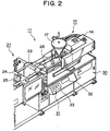
- FIG. 2 is a perspective view of the injection molding machine according to the embodiment of the present invention.
- numeral 11 denotes an injection molding machine
- numeral 12 denotes an injection unit.
- the injection unit 12 has a heating cylinder 13 in which an unillustrated screw is disposed rotatably and in an advancingly-retreatively movable manner.
- Drive means 14 rotates, and advances or retreats the screw.
- the screw is retreated while being rotated in a regular direction, so that resin is supplied from a hopper 17 and heated in the heating cylinder 13, and molten resin is accumulated in a space located ahead of an unillustrated screw head.
- the screw is advanced so as to inject the molten resin from an unillustrated injection nozzle.
- a mold unit 21 is disposed in front (on the left side in FIG. 2) of the injection unit 12.
- the mold unit 21 includes a stationary platen 23, a movable platen 24, an unillustrated stationary mold attached to the stationary platen 23, an unillustrated movable mold attached to the movable platen 24, and a mold clamping apparatus 25.
- the mold clamping apparatus 25 advances and retracts the movable platen 24 in order to bring the movable mold into contact with the stationary mold and separate the movable mold from the stationary mold, thereby performing mold closing operation, mold clamping operation, and mold opening operation.
- a frame 30 is disposed under the injection unit 12, and a control panel 31 is disposed on the front face of the frame 30.
- On the control panel 31 are disposed an input keyboard 32 with which an operator sets molding conditions and the like and a display screen (CRT) 33 serving as a display section for displaying the molding conditions and the like.
- a controller 27 When the operator operates an operation section 25 and the keyboard 32, the controller 27 generates predetermined signals to operate the injection unit 12 and the mold unit 21. That is, in order to perform injection molding, the controller 27 operates the injection unit 12 and the mold unit 21 based on the molding conditions and the like that the operator has set through operation of the keyboard 32.
- the operator must perform mold exchange operation, adjustment of the operation of the mold unit 21, adjustment of the temperature of the mold unit 21, heating of the heating cylinder 13, and charging of resin into the hopper 17.
- the operator must perform an operation for increasing the temperature of the mold unit 21, purging, exchange of resins, change of colors, removal of resin remaining within the heating cylinder 13, setting of molding conditions suitable for the molding unit 21, and starting up of molding.
- the temperature of a mold and molding state may become unstable at the startup of a first molding cycle. Therefore, if a subsequent molding cycle is performed while the molding conditions for the first molding cycle are maintained unchanged, over-pack may occur.
- detection means 52 formed of a switch or the like is disposed on the stationary platen 23 and the movable platen 24 in order to detect an operation performed by the operator of the injection molding machine 11.
- a detection signal generated by means of the detection means 52 is sent to the controller 27.
- Display means 53 of the controller 27 generates a display signal based on the detection signal and sends the display signal to the display screen 33.
- the display screen 33 displays a warning message or the like that calls the operator' s attention based on the display signal.
- the display screen 33 and the display means 53 constitute warning means.
- cancellation means 54 of the controller 27 cancels or erases the warning message or the like on the display screen 33 based on control signals from the injection unit 12 and the mold unit 21 and operation signals from operation means such as the operation section 28 and the keyboard 32.
- unillustrated operation judging means provided within the controller 27 makes judgment as to whether the injection molding machine 11 has been correctly operated, based on the control signals and operation signals, and sends the result of judgment to the cancellation means 54.
- the detection means 52 detects this mold exchange operation and outputs a detection signal.
- the display means 53 of the controller 27 operates the display screen 33 it, order to display a warning message that calls the operator' s attention to confirm whether the molding conditions are suited to the newly attached stationary and movable molds.
- the detection means 52 formed of a switch or the like detects the fact that the mold exchange operation has been performed.
- the performance of the mold exchange operation can be detected through the fact that an unillustrated power supply has been turned on or the fact that the thickness of the mold has been adjusted.
- the mold opening force is decreased automatically (e.g., to 30% or less the usual force) during the injection molding preparation period. Further, if the mold opening operation is not performed until the molds are opened to the limit during the period of injection molding preparation, operation of the injection molding machine 11 can not be started in any modes (manual, semi-automatic, and full-automatic).
- the display of the message can be canceled or erased through operation of an on/off key provided on the display screen 33.
- a warning message "Please perform purge” or a like message is displayed on the display screen 33.
- another preset time e.g., 30 minutes
- the molding conditions are automatically changed such that injection molding is performed with a shortened metering stroke and a reduced pressure.
- ordinary molding conditions are automatically set.
- the mode in which molding conditions are changed at the startup of the first molding operation can be turned on or off.
- controller 27 includes the cancellation means 54 which cancels the warning display when the operator correctly operates the injection molding machine 11 after being warned, the operator does not have to perform any operation such as operation of the keyboard 32 for canceling the warning display, so that work efficiency is improved.
- a warning message is displayed on the display screen 33 in order to call the operator's attention.
- the operator's attention may be called through use of a sound output from a speaker or the like, or use of an optical output from a display lamp or the like.
Landscapes
- Engineering & Computer Science (AREA)
- Manufacturing & Machinery (AREA)
- Mechanical Engineering (AREA)
- Injection Moulding Of Plastics Or The Like (AREA)
Abstract
Description
Claims (4)
- A warning apparatus for an injection molding machine comprising:(a) detection means for detecting an operation performed by an operator of the injection molding machine;(b) warning means for warning the operator in response to a detection signal from said detection means; and(c) cancellation means for canceling the warning when the operator correctly operates the injection molding machine.
- A warning apparatus for an injection molding machine according to Claim 1, wherein(a) said warning means includes a display section for performing display and display means for operating said display section based on a detection signal from said detection means in order to display a warning for the operator; and(b) said cancellation means cancels the display when the operator correctly operates the injection molding machine.
- A warning apparatus for an injection molding machine according to Claim 1, further comprising operation judging means for making judgment as to whether the injection molding machine is operated correctly, based on control signals from the injection molding machine and operation signals from operation means, wherein said cancellation means cancels the warning based on the result of judgment made by said operation judging means.
- A warning apparatus for an injection molding machine according to Claim 3, wherein said control signals are sent from at least one of an injection unit and a mold unit.
Applications Claiming Priority (3)
| Application Number | Priority Date | Filing Date | Title |
|---|---|---|---|
| JP193737/97 | 1997-07-18 | ||
| JP19373797 | 1997-07-18 | ||
| JP9193737A JPH1134137A (en) | 1997-07-18 | 1997-07-18 | Warning apparatus of injection machine |
Publications (3)
| Publication Number | Publication Date |
|---|---|
| EP0891852A2 true EP0891852A2 (en) | 1999-01-20 |
| EP0891852A3 EP0891852A3 (en) | 2000-12-27 |
| EP0891852B1 EP0891852B1 (en) | 2011-05-25 |
Family
ID=16312980
Family Applications (1)
| Application Number | Title | Priority Date | Filing Date |
|---|---|---|---|
| EP98113207A Expired - Lifetime EP0891852B1 (en) | 1997-07-18 | 1998-07-15 | Warning apparatus for an injection molding machine |
Country Status (8)
| Country | Link |
|---|---|
| US (1) | US5995009A (en) |
| EP (1) | EP0891852B1 (en) |
| JP (1) | JPH1134137A (en) |
| KR (1) | KR100292254B1 (en) |
| CN (1) | CN1077494C (en) |
| AT (1) | ATE510674T1 (en) |
| SG (1) | SG72841A1 (en) |
| TW (1) | TW446619B (en) |
Families Citing this family (11)
| Publication number | Priority date | Publication date | Assignee | Title |
|---|---|---|---|---|
| JP4048184B2 (en) * | 2004-03-30 | 2008-02-13 | 日精樹脂工業株式会社 | Abnormality monitoring system for molding machines |
| JP4799156B2 (en) * | 2005-12-06 | 2011-10-26 | 東洋機械金属株式会社 | Molding machine |
| JP5079362B2 (en) * | 2007-03-23 | 2012-11-21 | 東洋機械金属株式会社 | Molding machine |
| CN101770217A (en) * | 2008-12-30 | 2010-07-07 | 鸿富锦精密工业(深圳)有限公司 | Display control system and display control method for numerically controlled molding machine |
| JP2014226883A (en) * | 2013-05-24 | 2014-12-08 | 東洋機械金属株式会社 | Molding machine |
| JP6594618B2 (en) | 2013-11-26 | 2019-10-23 | 三星電子株式会社 | Vacuum insulation, insulation box and refrigerator |
| JP6013695B2 (en) * | 2015-02-24 | 2016-10-25 | ファナック株式会社 | Injection molding system with additional injection device |
| JP6305963B2 (en) | 2015-08-17 | 2018-04-04 | 株式会社ソディック | Injection molding machine support system and injection molding machine support method |
| TWI680048B (en) * | 2016-03-04 | 2019-12-21 | 台達電子工業股份有限公司 | Control system and method of injection molding machine |
| CN106514977A (en) * | 2016-11-14 | 2017-03-22 | 许海石 | Accurate and efficient injection molding machine control system with remote monitoring function |
| JP7391526B2 (en) * | 2019-03-29 | 2023-12-05 | 住友重機械工業株式会社 | Molding machine and computer program |
Citations (2)
| Publication number | Priority date | Publication date | Assignee | Title |
|---|---|---|---|---|
| JPH02150328A (en) * | 1988-12-01 | 1990-06-08 | Sumitomo Heavy Ind Ltd | Setting process for molding program of injection molding machine |
| JPH09254222A (en) * | 1996-03-26 | 1997-09-30 | Sumitomo Heavy Ind Ltd | Protecting apparatus of injection molding machine |
Family Cites Families (8)
| Publication number | Priority date | Publication date | Assignee | Title |
|---|---|---|---|---|
| JPS59158237A (en) * | 1983-02-28 | 1984-09-07 | Toshiba Mach Co Ltd | Control apparatus of injection molding apparatus |
| JPS61220818A (en) * | 1985-03-28 | 1986-10-01 | Fanuc Ltd | Injection molding machine indicating measuring and kneading condition by graph |
| JPS62170317A (en) * | 1986-01-24 | 1987-07-27 | Fanuc Ltd | Detecting device for various kinds of erroneously set values of injection molding machine |
| DE3744804C2 (en) * | 1986-04-01 | 1990-12-06 | Toshiba Kikai K.K., Tokio/Tokyo, Jp | |
| JP2727139B2 (en) * | 1991-05-18 | 1998-03-11 | ファナック株式会社 | Operating time analyzer for injection molding machines |
| US5325287A (en) * | 1992-09-30 | 1994-06-28 | The Foxboro Company | Decoupled display and control system |
| JPH07232364A (en) * | 1994-02-24 | 1995-09-05 | Fanuc Ltd | Injection molder equipped with display equipment |
| US5640467A (en) * | 1994-03-30 | 1997-06-17 | Ricoh Company, Ltd. | Image forming apparatus which monitors hardware errors of a controller of a copying-inhibited function |
-
1997
- 1997-07-18 JP JP9193737A patent/JPH1134137A/en active Pending
-
1998
- 1998-07-06 US US09/110,209 patent/US5995009A/en not_active Expired - Lifetime
- 1998-07-07 TW TW087111007A patent/TW446619B/en not_active IP Right Cessation
- 1998-07-08 SG SG1998001597A patent/SG72841A1/en unknown
- 1998-07-15 AT AT98113207T patent/ATE510674T1/en active
- 1998-07-15 EP EP98113207A patent/EP0891852B1/en not_active Expired - Lifetime
- 1998-07-15 KR KR1019980028568A patent/KR100292254B1/en not_active IP Right Cessation
- 1998-07-15 CN CN98103021A patent/CN1077494C/en not_active Expired - Fee Related
Patent Citations (2)
| Publication number | Priority date | Publication date | Assignee | Title |
|---|---|---|---|---|
| JPH02150328A (en) * | 1988-12-01 | 1990-06-08 | Sumitomo Heavy Ind Ltd | Setting process for molding program of injection molding machine |
| JPH09254222A (en) * | 1996-03-26 | 1997-09-30 | Sumitomo Heavy Ind Ltd | Protecting apparatus of injection molding machine |
Non-Patent Citations (2)
| Title |
|---|
| PATENT ABSTRACTS OF JAPAN vol. 014, no. 395 (M-1016), 27 August 1990 (1990-08-27) & JP 02 150328 A (SUMITOMO HEAVY IND LTD), 8 June 1990 (1990-06-08) * |
| PATENT ABSTRACTS OF JAPAN vol. 1998, no. 01, 30 January 1998 (1998-01-30) & JP 09 254222 A (SUMITOMO HEAVY IND LTD), 30 September 1997 (1997-09-30) * |
Also Published As
| Publication number | Publication date |
|---|---|
| KR100292254B1 (en) | 2001-06-01 |
| ATE510674T1 (en) | 2011-06-15 |
| SG72841A1 (en) | 2000-05-23 |
| TW446619B (en) | 2001-07-21 |
| EP0891852A3 (en) | 2000-12-27 |
| EP0891852B1 (en) | 2011-05-25 |
| KR19990013881A (en) | 1999-02-25 |
| CN1077494C (en) | 2002-01-09 |
| US5995009A (en) | 1999-11-30 |
| JPH1134137A (en) | 1999-02-09 |
| CN1209384A (en) | 1999-03-03 |
Similar Documents
| Publication | Publication Date | Title |
|---|---|---|
| US5995009A (en) | Warning apparatus for an injection molding machine | |
| WO2015060315A1 (en) | Molding condition diagnostic device | |
| JP2012135949A (en) | Mold monitoring apparatus | |
| JPH09267163A (en) | Method for deciding normal or defective quality of product in die casting machine | |
| JP2012135950A (en) | Mold monitoring apparatus | |
| JP3162228B2 (en) | Control method of injection molding machine | |
| JP3875486B2 (en) | Injection molding machine | |
| JPH0866951A (en) | Control method of injection molding machine | |
| JP2007210347A (en) | Injection molding machine | |
| JP3467360B2 (en) | Injection molding machine | |
| JPH06210691A (en) | Molding machine with molding condition determination support function | |
| JPH1128725A (en) | Thermoplastic resin molding system | |
| JPH0655595A (en) | Method and device for detecting abnormality of toggle type mold clamping force | |
| JPH06198694A (en) | Mold clamping force control device | |
| JPS6219425A (en) | Mold-clamping monitoring device for injection molder | |
| JPH06328527A (en) | Method for injection molding and injection molding machine | |
| JP3241643B2 (en) | Control device for injection molding machine | |
| JP3517282B2 (en) | Ejector condition setting monitoring method | |
| JP2935092B2 (en) | Control method of injection molding machine | |
| JPH06194294A (en) | Melt flow regulator for die casting mold | |
| JP3256932B2 (en) | Pre-plasticizer for injection molding machine | |
| JPH06190887A (en) | Molding machine with function of analyzing cause of nonconformity of molded product | |
| KR19990041963A (en) | Preheating device of mold base | |
| JP2002307155A (en) | Die for metal injection molding | |
| JPH04135821A (en) | Sprue ejecting device |
Legal Events
| Date | Code | Title | Description |
|---|---|---|---|
| PUAI | Public reference made under article 153(3) epc to a published international application that has entered the european phase |
Free format text: ORIGINAL CODE: 0009012 |
|
| AK | Designated contracting states |
Kind code of ref document: A2 Designated state(s): AT CH DE FR GB LI NL |
|
| AX | Request for extension of the european patent |
Free format text: AL;LT;LV;MK;RO;SI |
|
| PUAL | Search report despatched |
Free format text: ORIGINAL CODE: 0009013 |
|
| AK | Designated contracting states |
Kind code of ref document: A3 Designated state(s): AT BE CH CY DE DK ES FI FR GB GR IE IT LI LU MC NL PT SE |
|
| AX | Request for extension of the european patent |
Free format text: AL;LT;LV;MK;RO;SI |
|
| 17P | Request for examination filed |
Effective date: 20010131 |
|
| AKX | Designation fees paid |
Free format text: AT CH DE FR GB LI NL |
|
| 17Q | First examination report despatched |
Effective date: 20070509 |
|
| GRAP | Despatch of communication of intention to grant a patent |
Free format text: ORIGINAL CODE: EPIDOSNIGR1 |
|
| GRAS | Grant fee paid |
Free format text: ORIGINAL CODE: EPIDOSNIGR3 |
|
| GRAA | (expected) grant |
Free format text: ORIGINAL CODE: 0009210 |
|
| AK | Designated contracting states |
Kind code of ref document: B1 Designated state(s): AT CH DE FR GB LI NL |
|
| REG | Reference to a national code |
Ref country code: GB Ref legal event code: FG4D |
|
| REG | Reference to a national code |
Ref country code: CH Ref legal event code: NV Representative=s name: E. BLUM & CO. AG PATENT- UND MARKENANWAELTE VSP Ref country code: CH Ref legal event code: EP |
|
| REG | Reference to a national code |
Ref country code: DE Ref legal event code: R096 Ref document number: 69842282 Country of ref document: DE Effective date: 20110707 |
|
| REG | Reference to a national code |
Ref country code: NL Ref legal event code: T3 |
|
| PGFP | Annual fee paid to national office [announced via postgrant information from national office to epo] |
Ref country code: CH Payment date: 20110725 Year of fee payment: 14 |
|
| PLBE | No opposition filed within time limit |
Free format text: ORIGINAL CODE: 0009261 |
|
| STAA | Information on the status of an ep patent application or granted ep patent |
Free format text: STATUS: NO OPPOSITION FILED WITHIN TIME LIMIT |
|
| 26N | No opposition filed |
Effective date: 20120228 |
|
| REG | Reference to a national code |
Ref country code: DE Ref legal event code: R097 Ref document number: 69842282 Country of ref document: DE Effective date: 20120228 |
|
| PGFP | Annual fee paid to national office [announced via postgrant information from national office to epo] |
Ref country code: GB Payment date: 20120711 Year of fee payment: 15 |
|
| PGFP | Annual fee paid to national office [announced via postgrant information from national office to epo] |
Ref country code: FR Payment date: 20120719 Year of fee payment: 15 Ref country code: DE Payment date: 20120711 Year of fee payment: 15 |
|
| PGFP | Annual fee paid to national office [announced via postgrant information from national office to epo] |
Ref country code: NL Payment date: 20120714 Year of fee payment: 15 |
|
| PGFP | Annual fee paid to national office [announced via postgrant information from national office to epo] |
Ref country code: AT Payment date: 20120626 Year of fee payment: 15 |
|
| REG | Reference to a national code |
Ref country code: NL Ref legal event code: V1 Effective date: 20140201 |
|
| REG | Reference to a national code |
Ref country code: CH Ref legal event code: PL |
|
| REG | Reference to a national code |
Ref country code: AT Ref legal event code: MM01 Ref document number: 510674 Country of ref document: AT Kind code of ref document: T Effective date: 20130715 |
|
| GBPC | Gb: european patent ceased through non-payment of renewal fee |
Effective date: 20130715 |
|
| REG | Reference to a national code |
Ref country code: FR Ref legal event code: ST Effective date: 20140331 |
|
| PG25 | Lapsed in a contracting state [announced via postgrant information from national office to epo] |
Ref country code: LI Free format text: LAPSE BECAUSE OF NON-PAYMENT OF DUE FEES Effective date: 20130731 Ref country code: CH Free format text: LAPSE BECAUSE OF NON-PAYMENT OF DUE FEES Effective date: 20130731 Ref country code: DE Free format text: LAPSE BECAUSE OF NON-PAYMENT OF DUE FEES Effective date: 20140201 Ref country code: GB Free format text: LAPSE BECAUSE OF NON-PAYMENT OF DUE FEES Effective date: 20130715 Ref country code: NL Free format text: LAPSE BECAUSE OF NON-PAYMENT OF DUE FEES Effective date: 20140201 |
|
| REG | Reference to a national code |
Ref country code: DE Ref legal event code: R119 Ref document number: 69842282 Country of ref document: DE Effective date: 20140201 |
|
| PG25 | Lapsed in a contracting state [announced via postgrant information from national office to epo] |
Ref country code: FR Free format text: LAPSE BECAUSE OF NON-PAYMENT OF DUE FEES Effective date: 20130731 Ref country code: AT Free format text: LAPSE BECAUSE OF NON-PAYMENT OF DUE FEES Effective date: 20130715 |