EP0891158B1 - Multiple antenna ablation apparatus and method with cooling element - Google Patents
Multiple antenna ablation apparatus and method with cooling element Download PDFInfo
- Publication number
- EP0891158B1 EP0891158B1 EP97915985A EP97915985A EP0891158B1 EP 0891158 B1 EP0891158 B1 EP 0891158B1 EP 97915985 A EP97915985 A EP 97915985A EP 97915985 A EP97915985 A EP 97915985A EP 0891158 B1 EP0891158 B1 EP 0891158B1
- Authority
- EP
- European Patent Office
- Prior art keywords
- electrode
- cooling medium
- probe
- tissue
- ablation
- Prior art date
- Legal status (The legal status is an assumption and is not a legal conclusion. Google has not performed a legal analysis and makes no representation as to the accuracy of the status listed.)
- Expired - Lifetime
Links
Images


Classifications
-
- A—HUMAN NECESSITIES
- A61—MEDICAL OR VETERINARY SCIENCE; HYGIENE
- A61B—DIAGNOSIS; SURGERY; IDENTIFICATION
- A61B18/00—Surgical instruments, devices or methods for transferring non-mechanical forms of energy to or from the body
- A61B18/18—Surgical instruments, devices or methods for transferring non-mechanical forms of energy to or from the body by applying electromagnetic radiation, e.g. microwaves
-
- A—HUMAN NECESSITIES
- A61—MEDICAL OR VETERINARY SCIENCE; HYGIENE
- A61B—DIAGNOSIS; SURGERY; IDENTIFICATION
- A61B18/00—Surgical instruments, devices or methods for transferring non-mechanical forms of energy to or from the body
- A61B18/04—Surgical instruments, devices or methods for transferring non-mechanical forms of energy to or from the body by heating
- A61B18/12—Surgical instruments, devices or methods for transferring non-mechanical forms of energy to or from the body by heating by passing a current through the tissue to be heated, e.g. high-frequency current
- A61B18/14—Probes or electrodes therefor
- A61B18/1477—Needle-like probes
-
- A—HUMAN NECESSITIES
- A61—MEDICAL OR VETERINARY SCIENCE; HYGIENE
- A61B—DIAGNOSIS; SURGERY; IDENTIFICATION
- A61B18/00—Surgical instruments, devices or methods for transferring non-mechanical forms of energy to or from the body
- A61B18/04—Surgical instruments, devices or methods for transferring non-mechanical forms of energy to or from the body by heating
- A61B18/12—Surgical instruments, devices or methods for transferring non-mechanical forms of energy to or from the body by heating by passing a current through the tissue to be heated, e.g. high-frequency current
- A61B18/14—Probes or electrodes therefor
- A61B18/1482—Probes or electrodes therefor having a long rigid shaft for accessing the inner body transcutaneously in minimal invasive surgery, e.g. laparoscopy
-
- A—HUMAN NECESSITIES
- A61—MEDICAL OR VETERINARY SCIENCE; HYGIENE
- A61B—DIAGNOSIS; SURGERY; IDENTIFICATION
- A61B18/00—Surgical instruments, devices or methods for transferring non-mechanical forms of energy to or from the body
- A61B18/18—Surgical instruments, devices or methods for transferring non-mechanical forms of energy to or from the body by applying electromagnetic radiation, e.g. microwaves
- A61B18/1815—Surgical instruments, devices or methods for transferring non-mechanical forms of energy to or from the body by applying electromagnetic radiation, e.g. microwaves using microwaves
-
- A—HUMAN NECESSITIES
- A61—MEDICAL OR VETERINARY SCIENCE; HYGIENE
- A61N—ELECTROTHERAPY; MAGNETOTHERAPY; RADIATION THERAPY; ULTRASOUND THERAPY
- A61N1/00—Electrotherapy; Circuits therefor
- A61N1/02—Details
- A61N1/04—Electrodes
- A61N1/06—Electrodes for high-frequency therapy
-
- A—HUMAN NECESSITIES
- A61—MEDICAL OR VETERINARY SCIENCE; HYGIENE
- A61N—ELECTROTHERAPY; MAGNETOTHERAPY; RADIATION THERAPY; ULTRASOUND THERAPY
- A61N1/00—Electrotherapy; Circuits therefor
- A61N1/40—Applying electric fields by inductive or capacitive coupling ; Applying radio-frequency signals
- A61N1/403—Applying electric fields by inductive or capacitive coupling ; Applying radio-frequency signals for thermotherapy, e.g. hyperthermia
-
- A—HUMAN NECESSITIES
- A61—MEDICAL OR VETERINARY SCIENCE; HYGIENE
- A61B—DIAGNOSIS; SURGERY; IDENTIFICATION
- A61B18/00—Surgical instruments, devices or methods for transferring non-mechanical forms of energy to or from the body
- A61B18/04—Surgical instruments, devices or methods for transferring non-mechanical forms of energy to or from the body by heating
- A61B18/12—Surgical instruments, devices or methods for transferring non-mechanical forms of energy to or from the body by heating by passing a current through the tissue to be heated, e.g. high-frequency current
- A61B18/1206—Generators therefor
-
- A—HUMAN NECESSITIES
- A61—MEDICAL OR VETERINARY SCIENCE; HYGIENE
- A61B—DIAGNOSIS; SURGERY; IDENTIFICATION
- A61B18/00—Surgical instruments, devices or methods for transferring non-mechanical forms of energy to or from the body
- A61B18/04—Surgical instruments, devices or methods for transferring non-mechanical forms of energy to or from the body by heating
- A61B18/12—Surgical instruments, devices or methods for transferring non-mechanical forms of energy to or from the body by heating by passing a current through the tissue to be heated, e.g. high-frequency current
- A61B18/14—Probes or electrodes therefor
- A61B18/1402—Probes for open surgery
-
- A—HUMAN NECESSITIES
- A61—MEDICAL OR VETERINARY SCIENCE; HYGIENE
- A61B—DIAGNOSIS; SURGERY; IDENTIFICATION
- A61B18/00—Surgical instruments, devices or methods for transferring non-mechanical forms of energy to or from the body
- A61B18/04—Surgical instruments, devices or methods for transferring non-mechanical forms of energy to or from the body by heating
- A61B18/12—Surgical instruments, devices or methods for transferring non-mechanical forms of energy to or from the body by heating by passing a current through the tissue to be heated, e.g. high-frequency current
- A61B18/14—Probes or electrodes therefor
- A61B18/1485—Probes or electrodes therefor having a short rigid shaft for accessing the inner body through natural openings
-
- A—HUMAN NECESSITIES
- A61—MEDICAL OR VETERINARY SCIENCE; HYGIENE
- A61B—DIAGNOSIS; SURGERY; IDENTIFICATION
- A61B18/00—Surgical instruments, devices or methods for transferring non-mechanical forms of energy to or from the body
- A61B18/04—Surgical instruments, devices or methods for transferring non-mechanical forms of energy to or from the body by heating
- A61B18/12—Surgical instruments, devices or methods for transferring non-mechanical forms of energy to or from the body by heating by passing a current through the tissue to be heated, e.g. high-frequency current
- A61B18/14—Probes or electrodes therefor
- A61B18/1492—Probes or electrodes therefor having a flexible, catheter-like structure, e.g. for heart ablation
-
- A—HUMAN NECESSITIES
- A61—MEDICAL OR VETERINARY SCIENCE; HYGIENE
- A61B—DIAGNOSIS; SURGERY; IDENTIFICATION
- A61B17/00—Surgical instruments, devices or methods, e.g. tourniquets
- A61B2017/00017—Electrical control of surgical instruments
- A61B2017/00022—Sensing or detecting at the treatment site
- A61B2017/00084—Temperature
- A61B2017/00101—Temperature using an array of thermosensors
-
- A—HUMAN NECESSITIES
- A61—MEDICAL OR VETERINARY SCIENCE; HYGIENE
- A61B—DIAGNOSIS; SURGERY; IDENTIFICATION
- A61B18/00—Surgical instruments, devices or methods for transferring non-mechanical forms of energy to or from the body
- A61B2018/00005—Cooling or heating of the probe or tissue immediately surrounding the probe
- A61B2018/00011—Cooling or heating of the probe or tissue immediately surrounding the probe with fluids
- A61B2018/00023—Cooling or heating of the probe or tissue immediately surrounding the probe with fluids closed, i.e. without wound contact by the fluid
-
- A—HUMAN NECESSITIES
- A61—MEDICAL OR VETERINARY SCIENCE; HYGIENE
- A61B—DIAGNOSIS; SURGERY; IDENTIFICATION
- A61B18/00—Surgical instruments, devices or methods for transferring non-mechanical forms of energy to or from the body
- A61B2018/00053—Mechanical features of the instrument of device
- A61B2018/00184—Moving parts
- A61B2018/00196—Moving parts reciprocating lengthwise
-
- A—HUMAN NECESSITIES
- A61—MEDICAL OR VETERINARY SCIENCE; HYGIENE
- A61B—DIAGNOSIS; SURGERY; IDENTIFICATION
- A61B18/00—Surgical instruments, devices or methods for transferring non-mechanical forms of energy to or from the body
- A61B2018/00053—Mechanical features of the instrument of device
- A61B2018/00273—Anchoring means for temporary attachment of a device to tissue
-
- A—HUMAN NECESSITIES
- A61—MEDICAL OR VETERINARY SCIENCE; HYGIENE
- A61B—DIAGNOSIS; SURGERY; IDENTIFICATION
- A61B18/00—Surgical instruments, devices or methods for transferring non-mechanical forms of energy to or from the body
- A61B2018/00315—Surgical instruments, devices or methods for transferring non-mechanical forms of energy to or from the body for treatment of particular body parts
- A61B2018/00452—Skin
- A61B2018/00476—Hair follicles
-
- A—HUMAN NECESSITIES
- A61—MEDICAL OR VETERINARY SCIENCE; HYGIENE
- A61B—DIAGNOSIS; SURGERY; IDENTIFICATION
- A61B18/00—Surgical instruments, devices or methods for transferring non-mechanical forms of energy to or from the body
- A61B2018/00571—Surgical instruments, devices or methods for transferring non-mechanical forms of energy to or from the body for achieving a particular surgical effect
- A61B2018/00577—Ablation
-
- A—HUMAN NECESSITIES
- A61—MEDICAL OR VETERINARY SCIENCE; HYGIENE
- A61B—DIAGNOSIS; SURGERY; IDENTIFICATION
- A61B18/00—Surgical instruments, devices or methods for transferring non-mechanical forms of energy to or from the body
- A61B2018/00636—Sensing and controlling the application of energy
- A61B2018/00666—Sensing and controlling the application of energy using a threshold value
- A61B2018/00678—Sensing and controlling the application of energy using a threshold value upper
-
- A—HUMAN NECESSITIES
- A61—MEDICAL OR VETERINARY SCIENCE; HYGIENE
- A61B—DIAGNOSIS; SURGERY; IDENTIFICATION
- A61B18/00—Surgical instruments, devices or methods for transferring non-mechanical forms of energy to or from the body
- A61B2018/00636—Sensing and controlling the application of energy
- A61B2018/00696—Controlled or regulated parameters
- A61B2018/00702—Power or energy
- A61B2018/00708—Power or energy switching the power on or off
-
- A—HUMAN NECESSITIES
- A61—MEDICAL OR VETERINARY SCIENCE; HYGIENE
- A61B—DIAGNOSIS; SURGERY; IDENTIFICATION
- A61B18/00—Surgical instruments, devices or methods for transferring non-mechanical forms of energy to or from the body
- A61B2018/00636—Sensing and controlling the application of energy
- A61B2018/00696—Controlled or regulated parameters
- A61B2018/00726—Duty cycle
-
- A—HUMAN NECESSITIES
- A61—MEDICAL OR VETERINARY SCIENCE; HYGIENE
- A61B—DIAGNOSIS; SURGERY; IDENTIFICATION
- A61B18/00—Surgical instruments, devices or methods for transferring non-mechanical forms of energy to or from the body
- A61B2018/00636—Sensing and controlling the application of energy
- A61B2018/00696—Controlled or regulated parameters
- A61B2018/00744—Fluid flow
-
- A—HUMAN NECESSITIES
- A61—MEDICAL OR VETERINARY SCIENCE; HYGIENE
- A61B—DIAGNOSIS; SURGERY; IDENTIFICATION
- A61B18/00—Surgical instruments, devices or methods for transferring non-mechanical forms of energy to or from the body
- A61B2018/00636—Sensing and controlling the application of energy
- A61B2018/00696—Controlled or regulated parameters
- A61B2018/00761—Duration
-
- A—HUMAN NECESSITIES
- A61—MEDICAL OR VETERINARY SCIENCE; HYGIENE
- A61B—DIAGNOSIS; SURGERY; IDENTIFICATION
- A61B18/00—Surgical instruments, devices or methods for transferring non-mechanical forms of energy to or from the body
- A61B2018/00636—Sensing and controlling the application of energy
- A61B2018/00773—Sensed parameters
- A61B2018/00779—Power or energy
-
- A—HUMAN NECESSITIES
- A61—MEDICAL OR VETERINARY SCIENCE; HYGIENE
- A61B—DIAGNOSIS; SURGERY; IDENTIFICATION
- A61B18/00—Surgical instruments, devices or methods for transferring non-mechanical forms of energy to or from the body
- A61B2018/00636—Sensing and controlling the application of energy
- A61B2018/00773—Sensed parameters
- A61B2018/00791—Temperature
- A61B2018/00797—Temperature measured by multiple temperature sensors
-
- A—HUMAN NECESSITIES
- A61—MEDICAL OR VETERINARY SCIENCE; HYGIENE
- A61B—DIAGNOSIS; SURGERY; IDENTIFICATION
- A61B18/00—Surgical instruments, devices or methods for transferring non-mechanical forms of energy to or from the body
- A61B2018/00636—Sensing and controlling the application of energy
- A61B2018/00773—Sensed parameters
- A61B2018/00827—Current
-
- A—HUMAN NECESSITIES
- A61—MEDICAL OR VETERINARY SCIENCE; HYGIENE
- A61B—DIAGNOSIS; SURGERY; IDENTIFICATION
- A61B18/00—Surgical instruments, devices or methods for transferring non-mechanical forms of energy to or from the body
- A61B2018/00636—Sensing and controlling the application of energy
- A61B2018/00773—Sensed parameters
- A61B2018/00875—Resistance or impedance
-
- A—HUMAN NECESSITIES
- A61—MEDICAL OR VETERINARY SCIENCE; HYGIENE
- A61B—DIAGNOSIS; SURGERY; IDENTIFICATION
- A61B18/00—Surgical instruments, devices or methods for transferring non-mechanical forms of energy to or from the body
- A61B2018/00636—Sensing and controlling the application of energy
- A61B2018/00773—Sensed parameters
- A61B2018/00892—Voltage
-
- A—HUMAN NECESSITIES
- A61—MEDICAL OR VETERINARY SCIENCE; HYGIENE
- A61B—DIAGNOSIS; SURGERY; IDENTIFICATION
- A61B18/00—Surgical instruments, devices or methods for transferring non-mechanical forms of energy to or from the body
- A61B18/04—Surgical instruments, devices or methods for transferring non-mechanical forms of energy to or from the body by heating
- A61B18/12—Surgical instruments, devices or methods for transferring non-mechanical forms of energy to or from the body by heating by passing a current through the tissue to be heated, e.g. high-frequency current
- A61B18/1206—Generators therefor
- A61B2018/124—Generators therefor switching the output to different electrodes, e.g. sequentially
-
- A—HUMAN NECESSITIES
- A61—MEDICAL OR VETERINARY SCIENCE; HYGIENE
- A61B—DIAGNOSIS; SURGERY; IDENTIFICATION
- A61B18/00—Surgical instruments, devices or methods for transferring non-mechanical forms of energy to or from the body
- A61B18/04—Surgical instruments, devices or methods for transferring non-mechanical forms of energy to or from the body by heating
- A61B18/12—Surgical instruments, devices or methods for transferring non-mechanical forms of energy to or from the body by heating by passing a current through the tissue to be heated, e.g. high-frequency current
- A61B18/1206—Generators therefor
- A61B2018/1246—Generators therefor characterised by the output polarity
- A61B2018/1253—Generators therefor characterised by the output polarity monopolar
-
- A—HUMAN NECESSITIES
- A61—MEDICAL OR VETERINARY SCIENCE; HYGIENE
- A61B—DIAGNOSIS; SURGERY; IDENTIFICATION
- A61B18/00—Surgical instruments, devices or methods for transferring non-mechanical forms of energy to or from the body
- A61B18/04—Surgical instruments, devices or methods for transferring non-mechanical forms of energy to or from the body by heating
- A61B18/12—Surgical instruments, devices or methods for transferring non-mechanical forms of energy to or from the body by heating by passing a current through the tissue to be heated, e.g. high-frequency current
- A61B18/1206—Generators therefor
- A61B2018/1246—Generators therefor characterised by the output polarity
- A61B2018/126—Generators therefor characterised by the output polarity bipolar
-
- A—HUMAN NECESSITIES
- A61—MEDICAL OR VETERINARY SCIENCE; HYGIENE
- A61B—DIAGNOSIS; SURGERY; IDENTIFICATION
- A61B18/00—Surgical instruments, devices or methods for transferring non-mechanical forms of energy to or from the body
- A61B18/04—Surgical instruments, devices or methods for transferring non-mechanical forms of energy to or from the body by heating
- A61B18/12—Surgical instruments, devices or methods for transferring non-mechanical forms of energy to or from the body by heating by passing a current through the tissue to be heated, e.g. high-frequency current
- A61B18/14—Probes or electrodes therefor
- A61B2018/1405—Electrodes having a specific shape
- A61B2018/1425—Needle
- A61B2018/143—Needle multiple needles
-
- A—HUMAN NECESSITIES
- A61—MEDICAL OR VETERINARY SCIENCE; HYGIENE
- A61B—DIAGNOSIS; SURGERY; IDENTIFICATION
- A61B18/00—Surgical instruments, devices or methods for transferring non-mechanical forms of energy to or from the body
- A61B18/04—Surgical instruments, devices or methods for transferring non-mechanical forms of energy to or from the body by heating
- A61B18/12—Surgical instruments, devices or methods for transferring non-mechanical forms of energy to or from the body by heating by passing a current through the tissue to be heated, e.g. high-frequency current
- A61B18/14—Probes or electrodes therefor
- A61B2018/1405—Electrodes having a specific shape
- A61B2018/1425—Needle
- A61B2018/1432—Needle curved
-
- A—HUMAN NECESSITIES
- A61—MEDICAL OR VETERINARY SCIENCE; HYGIENE
- A61B—DIAGNOSIS; SURGERY; IDENTIFICATION
- A61B18/00—Surgical instruments, devices or methods for transferring non-mechanical forms of energy to or from the body
- A61B18/04—Surgical instruments, devices or methods for transferring non-mechanical forms of energy to or from the body by heating
- A61B18/12—Surgical instruments, devices or methods for transferring non-mechanical forms of energy to or from the body by heating by passing a current through the tissue to be heated, e.g. high-frequency current
- A61B18/14—Probes or electrodes therefor
- A61B2018/1405—Electrodes having a specific shape
- A61B2018/1435—Spiral
-
- A—HUMAN NECESSITIES
- A61—MEDICAL OR VETERINARY SCIENCE; HYGIENE
- A61B—DIAGNOSIS; SURGERY; IDENTIFICATION
- A61B18/00—Surgical instruments, devices or methods for transferring non-mechanical forms of energy to or from the body
- A61B18/04—Surgical instruments, devices or methods for transferring non-mechanical forms of energy to or from the body by heating
- A61B18/12—Surgical instruments, devices or methods for transferring non-mechanical forms of energy to or from the body by heating by passing a current through the tissue to be heated, e.g. high-frequency current
- A61B18/14—Probes or electrodes therefor
- A61B2018/1472—Probes or electrodes therefor for use with liquid electrolyte, e.g. virtual electrodes
-
- A—HUMAN NECESSITIES
- A61—MEDICAL OR VETERINARY SCIENCE; HYGIENE
- A61B—DIAGNOSIS; SURGERY; IDENTIFICATION
- A61B18/00—Surgical instruments, devices or methods for transferring non-mechanical forms of energy to or from the body
- A61B18/04—Surgical instruments, devices or methods for transferring non-mechanical forms of energy to or from the body by heating
- A61B18/12—Surgical instruments, devices or methods for transferring non-mechanical forms of energy to or from the body by heating by passing a current through the tissue to be heated, e.g. high-frequency current
- A61B18/14—Probes or electrodes therefor
- A61B18/16—Indifferent or passive electrodes for grounding
- A61B2018/162—Indifferent or passive electrodes for grounding located on the probe body
-
- A—HUMAN NECESSITIES
- A61—MEDICAL OR VETERINARY SCIENCE; HYGIENE
- A61B—DIAGNOSIS; SURGERY; IDENTIFICATION
- A61B2218/00—Details of surgical instruments, devices or methods for transferring non-mechanical forms of energy to or from the body
- A61B2218/001—Details of surgical instruments, devices or methods for transferring non-mechanical forms of energy to or from the body having means for irrigation and/or aspiration of substances to and/or from the surgical site
- A61B2218/002—Irrigation
-
- A—HUMAN NECESSITIES
- A61—MEDICAL OR VETERINARY SCIENCE; HYGIENE
- A61M—DEVICES FOR INTRODUCING MEDIA INTO, OR ONTO, THE BODY; DEVICES FOR TRANSDUCING BODY MEDIA OR FOR TAKING MEDIA FROM THE BODY; DEVICES FOR PRODUCING OR ENDING SLEEP OR STUPOR
- A61M25/00—Catheters; Hollow probes
- A61M25/0067—Catheters; Hollow probes characterised by the distal end, e.g. tips
- A61M25/0068—Static characteristics of the catheter tip, e.g. shape, atraumatic tip, curved tip or tip structure
- A61M25/007—Side holes, e.g. their profiles or arrangements; Provisions to keep side holes unblocked
-
- A—HUMAN NECESSITIES
- A61—MEDICAL OR VETERINARY SCIENCE; HYGIENE
- A61N—ELECTROTHERAPY; MAGNETOTHERAPY; RADIATION THERAPY; ULTRASOUND THERAPY
- A61N5/00—Radiation therapy
- A61N5/02—Radiation therapy using microwaves
- A61N5/04—Radiators for near-field treatment
Definitions
- This invention relates generally to an ablation apparatus with an internally cooled electrode, and more particularly to an electrode with a closed looped cooling device positioned in an electrode lumen, and an electrode sidewall port isolated from a cooling medium flowing through the closed looped cooling device.
- hyperthermia As a tool for treatment of tumors. It is known that elevating the temperature of tumors is helpful in the treatment and management of cancerous tissues. The mechanisms of selective cancer cell eradication by hyperthermia are not completely understood. However, four cellular effects of hyperthermia on cancerous tissue have been proposed, (i) changes in cell or nuclear membrane permeability or fluidity, (ii) cytoplasmic lysomal disintegration, causing release of digestive enzymes, (iii) protein thermal damage affecting cell respiration and the synthesis of DNA or RNA and (iv) potential excitation of immunologic systems. Treatment methods for applying heat to tumors include the use of direct contact radio-frequency (RF) applicators, microwave radiation, inductively coupled RF fields, ultrasound, and a variety of simple thermal conduction techniques.
- RF radio-frequency
- RF ablation electrodes tend to impede out when used at higher power levels.
- the tissue adjacent to the electrode surface tends to char.
- cooled electrodes are found in U.S. Patents Nos.: 4,290,435; 4,140,130, 4,881,543; 5,334,193; 5,342,357; 5,348,554; 5,423,811; 5,423,807; 5,437,662; and 5,462,521
- Another object of the invention is to provide an ablation apparatus and method with a cooled ablation electrode.
- Yet another object of the invention is to provide an ablation apparatus and method with a closed loop cooled ablation electrode.
- a further object of the invention is to provide an ablation apparatus and method with a closed loop cooled ablation electrode and an electrode sidewall port that is isolated from a cooling medium flowing through the ablation electrode.
- Still another object of the invention is to provide an ablation apparatus and method with a closed loop cooled ablation electrode, an electrode sidewall port isolated from a cooling medium flowing through the ablation electrode and a probe with a sensor that is advanced in and out of the sideport.
- Another object of the invention is to provide an ablation apparatus and method with a closed loop cooled ablation electrode, an electrode sidewall port isolated from a cooling medium flowing through the ablation electrode and an infusion medium introduced into a selected tissue site through the sidewall port.
- an ablation apparatus that has a handpiece, an electrode extending from a handpiece distal end, a probe, a thermal sensor and an energy source.
- the electrode includes a distal end, a lumen, a cooling medium inlet conduit and a cooling medium exit conduit. Both conduits extend through the electrode lumen to an electrode distal end.
- the probe is at least partially positioned in the electrode lumen and configured to be advanced and retracted in and out of the sidewall port.
- the thermal sensor is supported by the probe.
- the electrode is coupled to an energy source.
- the present invention is also a method for creating an ablation volume in a selected tissue mass.
- An ablation device is provided that has a handpiece, an electrode, a probe and a thermal sensor supported by the probe.
- the electrode includes a distal end, a lumen, a cooling medium inlet conduit coupled to a cooling medium outlet conduit which both extend through the electrode lumen to the electrode's distal end.
- a sidewall port is formed in a sidewall of the electrode and is isolated from a cooling medium flowing through the electrode.
- the electrode is inserted into the selected tissue mass.
- a distal end of the probe is advanced from the aperture into the selected tissue. At least a portion of an electrode ablation surface is cooled.
- Electromagnetic energy is delivered from the electrode to the selected tissue mass. Temperature is measured at a site in the selected tissue mass, and an ablation volume is created.
- the tissue interface adjacent to the electrode can begin to char and conductivity through the tissue decreases.
- a cooling medium the tissue interface remains at a temperature suitable for the delivery of electromagnetic energy to the periphery of the desired ablation site.
- one or more probes, with associated sensors are deployed into the desired ablation site. The ablation is monitored and controlled. Sensors can be positioned not only at the distal ends of the probes but also at intermediate positions. This permits monitoring of the ablation process between the electrode and the periphery of the targeted ablation volume.
- an ablation apparatus 10 includes a handpiece 11, an electrode 12, a cooling medium inlet conduit 14, a cooling medium outlet conduit 16 and a cap 18, with tapered distal end, that create a closed loop cooling system.
- a variety of different cooling mediums can be used including but not limited to gas, cooled air, refrigerated air, compressed air, freon, water, alcohol, saline and the like.
- a first sidewall port 20 is formed in a sidewall of electrode 12.
- a second sidewall port 22 may also be included. First and second sidewall ports can be windows formed in electrode 12 which create a mechanical weak spot in electrode 12.
- a first probe 24 is positioned in an electrode lumen and capable of being advanced and retracted in and out of first sidewall port 20.
- An optional second probe 26 is also positioned in the electrode lumen and is capable of being advanced and retracted to a selected tissue ablation side through second sidewall port 22.
- Electrode 12 has an exterior ablation energy delivery surface which delivers electromagnetic energy to the selected tissue ablation mass, and may have a tapered or sharpened distal end.
- electrode 12 can have an exterior ablation energy delivery surface length of 0.25 inches or less, and an outer diameter for electrode 12 of about 0.072 inches or less.
- Each probe 24 and 26 can be formed of a variety of materials, including but not limited to stainless steel, shaped memory metals and the like. The size of probes 24 and 26 vary depending on the medical application. For the treatment of tumors, probes 24 and 26 have a length extending from the sidewall ports into tissue of 3 cm or less.
- a first sensor 28 can be supported by probe 24 on an interior or exterior surface. First sensor 28 is preferably positioned at a distal end of probe 24
- a second sensor 30 may be positioned on probe 24 somewhere intermediate between an exterior surface of electrode 12 and the distal end of probe 24. Preferably, second sensor 30 is located at a position where it can sense temperature at a midpoint in a selected tissue ablation volume.
- Second sensor 30 is useful to determine if probe 24 has encountered an obstruction, such as a blood vessel, to the ablation process. If first sensor 28 measures a higher temperature than second sensor 30, then this can indicate that second sensor 30 is close to a circulatory vessel. When this occurs, ablation energy is carried away by the vessel Similarly, second probe 26 can also include one or more sensors. A third sensor 32 can be positioned at an exterior surface of electrode 12.
- Sensors 28, 30 and 32 permit accurate measurement of temperature at a tissue site in order to determine, (i) the extent of ablation, (ii) the amount of ablation, (iii) whether or not further ablation is needed and (iv) the boundary or periphery of the ablated mass. Further, sensors 28, 30 and 32 prevent non-targeted tissue from being destroyed or ablated.
- Sensors 28, 30 and 32 are of conventional design, including but not limited to thermistors, thermocouples, resistive wires, and the like.
- Suitable thermal sensors 24 include a T type thermocouple with copper constantene, J type, E type, K type, fiber optics, resistive wires, thermocouple IR detectors, and the like. Sensors 28, 30 and 32 need not be thermal sensors.
- Sensors 28, 30 and 32 measure temperature and/or impedance to permit monitoring and a desired level of ablation to be achieved without destroying too much tissue. This reduces damage to tissue surrounding the targeted mass to be ablated. By monitoring the temperature at various points within the interior of the selected tissue mass, a determination of the selected tissue mass periphery can be made, as well as a determination of when ablation is complete. If at any time sensor 28, 30 or 32 determines that a desired ablation temperature is exceeded, then an appropriate feedback signal is received at energy source 34 which then regulates the amount of energy delivered to electrode 12, as more fully explained hereafter.
- Electrode 12 is coupled to an electromagnetic energy source 34 by wiring, soldering, connection to a common couplet, and the like Electrode 12 can be independently coupled to electromagnetic energy source 34 from probes 24 and 26. Electrode 12, and probes 24 and 26 may be multiplexed so that when energy is delivered to electrode 12 it is not delivered to probes 24 and 26. Electromagnetic energy power source can be an RF source, microwave source, shortwave source, and the like
- Electrode 12 is constructed to be rigid enough so that it can be introduced percutaneously or laparoscopically through tissue without an introducer
- the actual length of electrode 12 depends on the location of the selected tissue mass to be ablated, its distance from the skin, its accessibility as well as whether or not the physician chooses a laparoscopic, percutaneous or other procedure. Suitable lengths include but are not limited to 17.5 cm, 25.0 cm. and 30.0 cm. Electrode 12, can be introduced through a guide to the selected tissue ablation site.
- An insulation sleeve 38 can be positioned in a surrounding relationship to an exterior surface of electrode 12. Insulation sleeve 38 can be moveable along electrode's 12 exterior surface in order to provide a variable length ablation energy delivery surface.
- insulation sleeve 38 can comprise a polyimide material.
- a sensor may be positioned on top of polyimide insulation sleeve 38.
- Polyamide insulation sleeve 18 is semi-rigid. The sensor can lay down substantially along the entire length of polyimide insulation sleeve 38.
- Handpiece 11 can serve the function of a handpiece and include markings to show the length of insulation sleeve 38 and the length of electrode's 12 exposed ablation energy delivery surface.
- cap 18 is illustrated as creating a closed loop cooling medium flow channel.
- Cap 18 is secured to the distal ends of conduits 14 and 16 by a variety of means, including but not limited to welding, soldering, application of an epoxy, and the like.
- Cap 18 can have a step which is secured to the distal end of electrode 12 by soldering, welding, press sit and the like.
- a "U' joint can be formed at the distal ends of conduits 16 and 18, as shown in Figure 3.
- cooling medium inlet conduit 14 only a portion of electrode has an interface with cooling medium inlet conduit 14.
- the diameters of cooling medium inlet conduit 14 and electrode 12 are dimensioned so that a tissue interface formed adjacent to the exterior surface of electrode 12 does not become sufficiently desiccated and charred to prevent the transfer of energy through the selected tissue ablation site to the periphery of the site.
- FIG. 5 The creation of a 4 cm diameter spherical ablation is illustrated in Figure 5.
- a 4 cm ablation energy delivery surface of electrode 12 is exposed.
- First sidewall port 20 is positioned 2 cm from a distal end of electrode 12.
- First probe 24 is advanced from electrode lumen with its distal end positioned at the periphery of the spherical ablation area.
- First sensor 28 is positioned at the distal end of first probe 24 and determines when the ablation has reached the periphery of the desired ablation area.
- Second sensor 30 is positioned midpoint on first probe 24 to monitor the transfer of electromagnetic energy through the desired ablation area, and determine if there are any obstructions to the ablation process at that position. Once the ablation is completed, first probe 24 is retracted back into the lumen of electrode 12.
- Electromagnetic energy delivered by electrode 12 causes the electrode/tissue interface at the electrode ablation delivery surface to heat, and return the heat to electrode 12. As more heat is applied and returned, the charring effect of electrode 12 increases. This can result in a loss electromagnetic energy conductivity through the selected tissue site.
- the inclusion of cooling with electrode 12 does not affect the effective delivery of electromagnetic energy to the selected tissue ablation site. Cooling permits the entire selected tissue ablation site to be ablated while reducing or eliminating the heating of the electrode/tissue interface tissue.
- probes 24 and 26 are each deployed out of the distal end of electrode 12 and introduced into the selected tissue mass. Probes 24 and 26 form a plane.
- insulation sleeve 38 can include one or more lumens for receiving secondary probes 24, 26 as well as additional probes which are deployed out of a distal end of insulation sleeve 38.
- Figure 8 illustrates four probes introduced out of different sidewall ports formed in the body of electrode 12. Some or all of the probes provide an anchoring function.
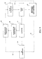
- FIG. 9 illustrates a block diagram of a temperature/impedance feedback system that can be used to control cooling medium flow rate through electrode 12.
- Electromagnetic energy is delivered to electrode 12 by energy source 34, and applied to tissue.
- a monitor 42 ascertains tissue impedance, based on the energy delivered to tissue, and compares the measured impedance value to a set value. if the measured impedance exceeds the set value a disabling signal 44 is transmitted to energy source 34, ceasing further delivery of energy to electrode 12. If measured impedance is within acceptable limits, energy continues to be applied to the tissue.
- tissue sensor 46 measures the temperature of tissue and/or electrode 12.
- a comparator 48 receives a signal representative of the measured temperature and compares this value to a pre-set signal representative of the desired temperature. Comparator 48 sends a signal to a flow regulator 50 representing a need for a higher cooling medium flow rate, if the tissue temperature is too high, or to maintain the flow rate if the temperature has not exceeded the desired temperature.
- An output 52 from temperature comparator 48 can be input to energy source 34 to regulate the amount of power delivered by power source 32.
- Output 54 from impedance monitor 106 can be input to flow regulator 50 to regulate fluid flow and thus control temperature of the tissue.
- ablation apparatus 10 is represented as a bipolar ablation device having an energy delivering electrode 12 and a ground electrode 56. Both electrodes 12 and 56 are connected to a primary side of transformer windings 58 and 60. The common primary winding 58 or 60 is magnetically coupled with a transformer core to secondary windings 58 and 60 respectively;
- the primary windings 58 of the first transformer t 1 couple the output voltage of ablation apparatus 10 to the secondary windings 58'.
- the primary windings 60 of the second transformer t 2 couple the output current of ablation apparatus 10 to the secondary windings 60'.
- Measuring circuits determine the root mean square (RMS) values or magnitudes of the current and voltage. These values, represented as voltages, are inputted to a diving circuit D to geometrically calculate, by dividing the RMS voltage value by the RMS current value, the impedance of the tissue site at sensor 46.
- RMS root mean square
- the output voltage of the divider circuit D is presented at the positive (+) input terminal of comparator A.
- a voltage source V o supplies a voltage across the variable resistor R v , thus allowing one to manually adjust the voltage presented at the negative input of comparator A. This voltage represents a maximum impedance value beyond which power will not be applied to electrode 12. Specifically, once the tissue is heated to a temperature corresponding to an impedance value greater than the maximum cut-off impedance, energy source 34 stops supplying energy to electrode 12.
- Comparator A can be of any of a commercially available type that is able to control the amplitude or pulse width modulation of energy source 34.
- the flow rate of cooling medium can be controlled based on the tissue impedance, as represented by signal 62, or based on tissue temperature, as represented by signal 64.
- the switch S is activated to allow the impedance signal 62 to enter the positive (+) input terminal of comparator A This signal along with the reference voltage applied to the negative (-) input terminal actuates comparator A to produce an output signal. If the selected tissue ablation site is heated to a biologically damaging temperature, the tissue impedance will exceed a selected impedance value seen at the negative (-) input terminal, thereby generating disabling signal 44 to disable energy source 34, ceasing the power supplied to electrode 12.
- the output signal of comparator A can be communicated to a pump 66. If the temperature of the selected tissue ablation site is too high, despite the tissue impedance falling within acceptable limits, pump 66 adjusts the rate of cooling medium flow applied to electrode 12 to decrease the temperature of electrode 12.
- the output signal of comparator A may either disable energy source's 34 energy output, depending on the tissue temperature as reflected by its impedance, or cool electrode 12 or perform both operations simultaneously.
Description
Claims (24)
- A tissue ablation apparatus (10), comprising:wherein the electrode is configured to be coupled to an energy source (34);an electrode (12) including a distal end sufficiently sharp to pierce tissue, and a lumen;a cooling medium inlet conduit (14) and a cooling medium exit conduit (16) both extending at least partially through the electrode lumen;said lumen terminating in at least one port (20,22) in the electrode isolated from a cooling medium flowing in the inlet and outlet conduits;
at least one probe (24, 26) at least partially positioned in the electrode lumen, wherein the at least one probe includes a distal portion configured to be advanced out of the port with at least one radius of curvature; and
at least one thermal sensor (28, 30, 32) coupled to at least one of the at least one probe. - The apparatus according to claim 1, wherein the cooling medium inlet and exit conduits form a closed loop at the electrode distal end.
- The apparatus according to claim 1, wherein the electrode lumen is configured to transport an infusion medium that remains isolated from the cooling medium.
- The apparatus according to claim 3, wherein the electrode is configured to transport the infusion medium through the electrode lumen to a tissue site through the at least one port.
- The apparatus according to claim 1, further comprising:an advancement and retraction member coupled to the at least one probe.
- The apparatus according to claim 1, wherein at least one of the at least one probes is configured to be coupled to the energy source, wherein at least a portion of the probe is a further electrode.
- The apparatus according to claim 1, wherein the at least one thermal sensor comprises a first thermal sensor and a second thermal sensor.
- The apparatus according to claim 7, wherein the first thermal sensor is positioned at a distal end of at least one of the at least one probe, and the second thermal sensor is positioned at a non-distal end location of the same probe.
- The apparatus according to claim 7, wherein said first thermal sensor is positioned on at least one of the at least one probe, and the second thermal sensor is positioned on another of the at least one probe.
- The apparatus according to claim 1, wherein the at least one thermal sensor is positioned at a distal end of at least one of the probes.
- The apparatus according to claim 1, further comprising:an insulation sleeve (38) positioned around an exterior surface of the electrode.
- The apparatus according to claim 11, wherein the insulation sleeve is moveable along a longitudinal axis of the electrode.
- The apparatus according to claim 1, wherein said at least one port comprises a first and a second port formed in the electrode.
- The apparatus according to claim 1, wherein the cooling medium inlet and cooling medium exit conduits are each constructed to add structural support to the electrode.
- The apparatus according to claim 1, wherein at least one of the at least one probe is deployable from the port and has a distal end geometry configured to retain the electrode in a fixed position when deployed.
- The apparatus according to claim 1, wherein the cooling medium inlet and cooling medium exit conduits are positioned adjacent to each other in the electrode lumen.
- The apparatus according to claim 1, further comprising:a comparator device (48) coupled to the at least one thermal sensor to compare a measured temperature of a tissue site to a predetermined temperature value and generating a signal representative of a difference between the measured temperature and the predetermined temperature.
- The apparatus according to claim 17, further comprising:a fluid control device (50) coupled to the inlet and exit conduits for regulating a rate of flow of the cooling medium through the conduits in response to the signal from the comparator device representative of the temperature difference to maintain the measured temperature at or below the predetermined temperature.
- The apparatus according to claim 1, further comprising:an energy output control device coupled to the energy source for regulating energy output to the apparatus.
- The apparatus according to claim 19, further comprising:a impedance monitoring device (42) for determining a value of tissue impedance based on an energy applied to the tissue;an impedance comparator device for comparing the determined impedance to a predetermined maximum impedance value, the impedance comparator device generating a signal if the determined impedance value exceeds the predetermined maximum impedance value; anda communication device for communicating a disabling signal to the energy source to cease further delivery of energy from the energy source to the apparatus.
- The apparatus according to claim 20, further comprising:a cooling medium control device (66) for regulating rate of flow of cooling medium through the inlet conduit and the exit conduit in response to the signal from the impedance comparator device representative of the impedance difference to maintain the measured impedance value at or below the predetermined maximum impedance value.
- The apparatus according to any preceding claim wherein said cooling medium inlet conduit is configured to be coupled to a cooling medium source.
- The apparatus according to any preceding claim, further comprising:an insulation sleeve positioned around an exterior surface of at least one of the at least one probes.
- The apparatus according to any preceding claim, wherein the energy source (34) is selected from a RF energy source and a microwave energy source.
Applications Claiming Priority (3)
| Application Number | Priority Date | Filing Date | Title |
|---|---|---|---|
| US08/616,928 US5810804A (en) | 1995-08-15 | 1996-03-15 | Multiple antenna ablation apparatus and method with cooling element |
| US616928 | 1996-03-15 | ||
| PCT/US1997/004098 WO1997033524A1 (en) | 1996-03-15 | 1997-03-14 | Multiple antenna ablation apparatus and method with cooling element |
Publications (2)
| Publication Number | Publication Date |
|---|---|
| EP0891158A1 EP0891158A1 (en) | 1999-01-20 |
| EP0891158B1 true EP0891158B1 (en) | 2004-09-22 |
Family
ID=24471567
Family Applications (1)
| Application Number | Title | Priority Date | Filing Date |
|---|---|---|---|
| EP97915985A Expired - Lifetime EP0891158B1 (en) | 1996-03-15 | 1997-03-14 | Multiple antenna ablation apparatus and method with cooling element |
Country Status (8)
| Country | Link |
|---|---|
| US (1) | US5810804A (en) |
| EP (1) | EP0891158B1 (en) |
| JP (2) | JP4001210B2 (en) |
| KR (1) | KR19990087805A (en) |
| AU (1) | AU2327197A (en) |
| DE (1) | DE69730824T2 (en) |
| ES (1) | ES2229345T3 (en) |
| WO (1) | WO1997033524A1 (en) |
Families Citing this family (218)
| Publication number | Priority date | Publication date | Assignee | Title |
|---|---|---|---|---|
| US6405732B1 (en) * | 1994-06-24 | 2002-06-18 | Curon Medical, Inc. | Method to treat gastric reflux via the detection and ablation of gastro-esophageal nerves and receptors |
| US6090105A (en) * | 1995-08-15 | 2000-07-18 | Rita Medical Systems, Inc. | Multiple electrode ablation apparatus and method |
| US6152899A (en) | 1996-03-05 | 2000-11-28 | Vnus Medical Technologies, Inc. | Expandable catheter having improved electrode design, and method for applying energy |
| US6139527A (en) * | 1996-03-05 | 2000-10-31 | Vnus Medical Technologies, Inc. | Method and apparatus for treating hemorrhoids |
| US6033397A (en) * | 1996-03-05 | 2000-03-07 | Vnus Medical Technologies, Inc. | Method and apparatus for treating esophageal varices |
| US6033398A (en) * | 1996-03-05 | 2000-03-07 | Vnus Medical Technologies, Inc. | Method and apparatus for treating venous insufficiency using directionally applied energy |
| US6036687A (en) * | 1996-03-05 | 2000-03-14 | Vnus Medical Technologies, Inc. | Method and apparatus for treating venous insufficiency |
| WO1998038936A1 (en) | 1997-03-04 | 1998-09-11 | Vnus Medical Technologies, Inc. | Method and apparatus for treating venous insufficiency using directionally applied energy |
| ES2353846T3 (en) | 1997-04-11 | 2011-03-07 | United States Surgical Corporation | APPLIANCE FOR RF ABLATION AND CONTROLLER OF THE SAME. |
| US6096037A (en) | 1997-07-29 | 2000-08-01 | Medtronic, Inc. | Tissue sealing electrosurgery device and methods of sealing tissue |
| US6104959A (en) | 1997-07-31 | 2000-08-15 | Microwave Medical Corp. | Method and apparatus for treating subcutaneous histological features |
| US6401719B1 (en) | 1997-09-11 | 2002-06-11 | Vnus Medical Technologies, Inc. | Method of ligating hollow anatomical structures |
| US6258084B1 (en) | 1997-09-11 | 2001-07-10 | Vnus Medical Technologies, Inc. | Method for applying energy to biological tissue including the use of tumescent tissue compression |
| US6179832B1 (en) * | 1997-09-11 | 2001-01-30 | Vnus Medical Technologies, Inc. | Expandable catheter having two sets of electrodes |
| US6200312B1 (en) * | 1997-09-11 | 2001-03-13 | Vnus Medical Technologies, Inc. | Expandable vein ligator catheter having multiple electrode leads |
| US6238389B1 (en) | 1997-09-30 | 2001-05-29 | Boston Scientific Corporation | Deflectable interstitial ablation device |
| US6014589A (en) * | 1997-11-12 | 2000-01-11 | Vnus Medical Technologies, Inc. | Catheter having expandable electrodes and adjustable stent |
| DE69923291T2 (en) * | 1998-02-19 | 2005-06-09 | Curon Medical Inc., Sunnyvale | ELECTRO-SURGERY DEVICE FOR THE TREATMENT OF CLOSURE MUSCLES |
| US5968041A (en) * | 1998-04-02 | 1999-10-19 | Vida Care, Inc. | Directable thermal energy delivery apparatus |
| US6623474B1 (en) * | 1998-06-04 | 2003-09-23 | Biosense Webster, Inc. | Injection catheter with needle stop |
| US6905476B2 (en) * | 1998-06-04 | 2005-06-14 | Biosense Webster, Inc. | Catheter with injection needle |
| US8079982B1 (en) | 1998-06-04 | 2011-12-20 | Biosense Webster, Inc. | Injection catheter with needle electrode |
| US6623473B1 (en) * | 1998-06-04 | 2003-09-23 | Biosense Webster, Inc. | Injection catheter with multi-directional delivery injection needle |
| US6575931B1 (en) | 1998-06-04 | 2003-06-10 | Biosense Webster, Inc. | Catheter with injection needle |
| US6165164A (en) * | 1999-03-29 | 2000-12-26 | Cordis Corporation | Catheter for injecting therapeutic and diagnostic agents |
| US7416547B2 (en) * | 1999-03-29 | 2008-08-26 | Biosense Webster Inc. | Injection catheter |
| US6540725B1 (en) * | 1998-06-04 | 2003-04-01 | Biosense Webster, Inc. | Injection catheter with controllably extendable injection needle |
| US5997534A (en) * | 1998-06-08 | 1999-12-07 | Tu; Hosheng | Medical ablation device and methods thereof |
| US6283962B1 (en) * | 1998-06-08 | 2001-09-04 | Quantum Therapeutics Corp. | Device for valvular annulus treatment and methods thereof |
| US7137980B2 (en) | 1998-10-23 | 2006-11-21 | Sherwood Services Ag | Method and system for controlling output of RF medical generator |
| US7901400B2 (en) | 1998-10-23 | 2011-03-08 | Covidien Ag | Method and system for controlling output of RF medical generator |
| US7364577B2 (en) | 2002-02-11 | 2008-04-29 | Sherwood Services Ag | Vessel sealing system |
| WO2000033909A1 (en) | 1998-12-09 | 2000-06-15 | Cook Incorporated | Hollow, curved, superelastic medical needle |
| US6203541B1 (en) * | 1999-04-23 | 2001-03-20 | Sherwood Services Ag | Automatic activation of electrosurgical generator bipolar output |
| US6306132B1 (en) | 1999-06-17 | 2001-10-23 | Vivant Medical | Modular biopsy and microwave ablation needle delivery apparatus adapted to in situ assembly and method of use |
| KR100375339B1 (en) * | 1999-12-03 | 2003-03-10 | 이종균 | Internal hemorrhoids remedy apparatus |
| US6564806B1 (en) | 2000-02-18 | 2003-05-20 | Thomas J. Fogarty | Device for accurately marking tissue |
| JP5090600B2 (en) | 2000-02-18 | 2012-12-05 | トーマス ジェイ. フォガーティー, | Improved device for accurately marking tissues |
| US6722371B1 (en) | 2000-02-18 | 2004-04-20 | Thomas J. Fogarty | Device for accurately marking tissue |
| US6770070B1 (en) * | 2000-03-17 | 2004-08-03 | Rita Medical Systems, Inc. | Lung treatment apparatus and method |
| AU2001249752A1 (en) * | 2000-03-31 | 2001-10-15 | Rita Medical Systems, Inc. | Tissue biopsy and treatment apparatus and method |
| US6546935B2 (en) | 2000-04-27 | 2003-04-15 | Atricure, Inc. | Method for transmural ablation |
| US6638277B2 (en) | 2000-07-06 | 2003-10-28 | Scimed Life Systems, Inc. | Tumor ablation needle with independently activated and independently traversing tines |
| US8251986B2 (en) | 2000-08-17 | 2012-08-28 | Angiodynamics, Inc. | Method of destroying tissue cells by eletroporation |
| US7387628B1 (en) | 2000-09-15 | 2008-06-17 | Boston Scientific Scimed, Inc. | Methods and systems for focused bipolar tissue ablation |
| US7740623B2 (en) | 2001-01-13 | 2010-06-22 | Medtronic, Inc. | Devices and methods for interstitial injection of biologic agents into tissue |
| US20040138621A1 (en) | 2003-01-14 | 2004-07-15 | Jahns Scott E. | Devices and methods for interstitial injection of biologic agents into tissue |
| US7087040B2 (en) | 2001-02-28 | 2006-08-08 | Rex Medical, L.P. | Apparatus for delivering ablation fluid to treat lesions |
| US6989004B2 (en) | 2001-02-28 | 2006-01-24 | Rex Medical, L.P. | Apparatus for delivering ablation fluid to treat lesions |
| US7008421B2 (en) * | 2002-08-21 | 2006-03-07 | Resect Medical, Inc. | Apparatus and method for tissue resection |
| DE60208780T2 (en) | 2001-02-28 | 2006-08-10 | Rex Medical, L.P. | DEVICE FOR APPLYING ABLATION FLUID FOR THE TREATMENT OF LESIONS |
| US20030032936A1 (en) * | 2001-08-10 | 2003-02-13 | Lederman Robert J. | Side-exit catheter and method for its use |
| US6994706B2 (en) | 2001-08-13 | 2006-02-07 | Minnesota Medical Physics, Llc | Apparatus and method for treatment of benign prostatic hyperplasia |
| US7344533B2 (en) * | 2001-09-28 | 2008-03-18 | Angiodynamics, Inc. | Impedance controlled tissue ablation apparatus and method |
| US7128739B2 (en) | 2001-11-02 | 2006-10-31 | Vivant Medical, Inc. | High-strength microwave antenna assemblies and methods of use |
| US6878147B2 (en) | 2001-11-02 | 2005-04-12 | Vivant Medical, Inc. | High-strength microwave antenna assemblies |
| US7967816B2 (en) | 2002-01-25 | 2011-06-28 | Medtronic, Inc. | Fluid-assisted electrosurgical instrument with shapeable electrode |
| US7294127B2 (en) * | 2002-03-05 | 2007-11-13 | Baylis Medical Company Inc. | Electrosurgical tissue treatment method |
| US8882755B2 (en) | 2002-03-05 | 2014-11-11 | Kimberly-Clark Inc. | Electrosurgical device for treatment of tissue |
| US6896675B2 (en) | 2002-03-05 | 2005-05-24 | Baylis Medical Company Inc. | Intradiscal lesioning device |
| US20050177209A1 (en) * | 2002-03-05 | 2005-08-11 | Baylis Medical Company Inc. | Bipolar tissue treatment system |
| US8043287B2 (en) | 2002-03-05 | 2011-10-25 | Kimberly-Clark Inc. | Method of treating biological tissue |
| US8518036B2 (en) | 2002-03-05 | 2013-08-27 | Kimberly-Clark Inc. | Electrosurgical tissue treatment method |
| US6752767B2 (en) | 2002-04-16 | 2004-06-22 | Vivant Medical, Inc. | Localization element with energized tip |
| US7197363B2 (en) | 2002-04-16 | 2007-03-27 | Vivant Medical, Inc. | Microwave antenna having a curved configuration |
| US20040077951A1 (en) * | 2002-07-05 | 2004-04-22 | Wei-Chiang Lin | Apparatus and methods of detection of radiation injury using optical spectroscopy |
| US7223264B2 (en) * | 2002-08-21 | 2007-05-29 | Resect Medical, Inc. | Thermal coagulation of tissue during tissue resection |
| US20060167445A1 (en) * | 2002-08-27 | 2006-07-27 | Gal Shafirstein | Selective conductive interstitial thermal therapy device |
| US20060173359A1 (en) * | 2002-09-30 | 2006-08-03 | Lin Wei C | Optical apparatus for guided liver tumor treatment and methods |
| US7044948B2 (en) | 2002-12-10 | 2006-05-16 | Sherwood Services Ag | Circuit for controlling arc energy from an electrosurgical generator |
| US7101387B2 (en) * | 2003-04-30 | 2006-09-05 | Scimed Life Systems, Inc. | Radio frequency ablation cooling shield |
| EP1617776B1 (en) | 2003-05-01 | 2015-09-02 | Covidien AG | System for programing and controlling an electrosurgical generator system |
| US7311703B2 (en) | 2003-07-18 | 2007-12-25 | Vivant Medical, Inc. | Devices and methods for cooling microwave antennas |
| WO2005032342A2 (en) * | 2003-09-30 | 2005-04-14 | Vanderbilt University | Methods and apparatus for optical spectroscopic detection of cell and tissue death |
| US7416549B2 (en) * | 2003-10-10 | 2008-08-26 | Boston Scientific Scimed, Inc. | Multi-zone bipolar ablation probe assembly |
| WO2005050151A1 (en) | 2003-10-23 | 2005-06-02 | Sherwood Services Ag | Thermocouple measurement circuit |
| US7155270B2 (en) * | 2003-10-24 | 2006-12-26 | Biosense Webster, Inc. | Catheter with multi-spine mapping assembly |
| US7396336B2 (en) | 2003-10-30 | 2008-07-08 | Sherwood Services Ag | Switched resonant ultrasonic power amplifier system |
| US7131860B2 (en) | 2003-11-20 | 2006-11-07 | Sherwood Services Ag | Connector systems for electrosurgical generator |
| US20050190982A1 (en) * | 2003-11-28 | 2005-09-01 | Matsushita Electric Industrial Co., Ltd. | Image reducing device and image reducing method |
| US7467015B2 (en) | 2004-04-29 | 2008-12-16 | Neuwave Medical, Inc. | Segmented catheter for tissue ablation |
| US7244254B2 (en) * | 2004-04-29 | 2007-07-17 | Micrablate | Air-core microwave ablation antennas |
| WO2005120376A2 (en) | 2004-06-02 | 2005-12-22 | Medtronic, Inc. | Ablation device with jaws |
| US7628786B2 (en) | 2004-10-13 | 2009-12-08 | Covidien Ag | Universal foot switch contact port |
| US9474564B2 (en) | 2005-03-31 | 2016-10-25 | Covidien Ag | Method and system for compensating for external impedance of an energy carrying component when controlling an electrosurgical generator |
| US7799019B2 (en) | 2005-05-10 | 2010-09-21 | Vivant Medical, Inc. | Reinforced high strength microwave antenna |
| WO2006138382A2 (en) | 2005-06-14 | 2006-12-28 | Micrablate, Llc | Microwave tissue resection tool |
| GB2434314B (en) * | 2006-01-03 | 2011-06-15 | Microsulis Ltd | Microwave applicator with dipole antenna |
| US8080009B2 (en) * | 2005-07-01 | 2011-12-20 | Halt Medical Inc. | Radio frequency ablation device for the destruction of tissue masses |
| US8512330B2 (en) * | 2005-07-01 | 2013-08-20 | Halt Medical Inc. | Ablation method |
| US8512333B2 (en) * | 2005-07-01 | 2013-08-20 | Halt Medical Inc. | Anchored RF ablation device for the destruction of tissue masses |
| US8734438B2 (en) | 2005-10-21 | 2014-05-27 | Covidien Ag | Circuit and method for reducing stored energy in an electrosurgical generator |
| US7947039B2 (en) | 2005-12-12 | 2011-05-24 | Covidien Ag | Laparoscopic apparatus for performing electrosurgical procedures |
| US7972328B2 (en) | 2006-01-24 | 2011-07-05 | Covidien Ag | System and method for tissue sealing |
| US8685016B2 (en) | 2006-01-24 | 2014-04-01 | Covidien Ag | System and method for tissue sealing |
| US8216223B2 (en) | 2006-01-24 | 2012-07-10 | Covidien Ag | System and method for tissue sealing |
| CA2574934C (en) | 2006-01-24 | 2015-12-29 | Sherwood Services Ag | System and method for closed loop monitoring of monopolar electrosurgical apparatus |
| US7513896B2 (en) | 2006-01-24 | 2009-04-07 | Covidien Ag | Dual synchro-resonant electrosurgical apparatus with bi-directional magnetic coupling |
| US9186200B2 (en) | 2006-01-24 | 2015-11-17 | Covidien Ag | System and method for tissue sealing |
| CA2574935A1 (en) | 2006-01-24 | 2007-07-24 | Sherwood Services Ag | A method and system for controlling an output of a radio-frequency medical generator having an impedance based control algorithm |
| US8147485B2 (en) | 2006-01-24 | 2012-04-03 | Covidien Ag | System and method for tissue sealing |
| US7651493B2 (en) | 2006-03-03 | 2010-01-26 | Covidien Ag | System and method for controlling electrosurgical snares |
| WO2007112103A1 (en) * | 2006-03-24 | 2007-10-04 | Neuwave Medical, Inc. | Energy delivery system |
| US8672932B2 (en) | 2006-03-24 | 2014-03-18 | Neuwave Medical, Inc. | Center fed dipole for use with tissue ablation systems, devices and methods |
| US10363092B2 (en) | 2006-03-24 | 2019-07-30 | Neuwave Medical, Inc. | Transmission line with heat transfer ability |
| WO2007126949A1 (en) * | 2006-03-31 | 2007-11-08 | Wilson-Cook Medical, Inc. | Electrosurgical cutting device |
| US7651492B2 (en) | 2006-04-24 | 2010-01-26 | Covidien Ag | Arc based adaptive control system for an electrosurgical unit |
| US10376314B2 (en) | 2006-07-14 | 2019-08-13 | Neuwave Medical, Inc. | Energy delivery systems and uses thereof |
| US11389235B2 (en) | 2006-07-14 | 2022-07-19 | Neuwave Medical, Inc. | Energy delivery systems and uses thereof |
| ATE459298T1 (en) * | 2006-09-08 | 2010-03-15 | Ethicon Endo Surgery Inc | SURGICAL INSTRUMENT FOR THE CONTROLLED PERFORMANCE OF MYOTOMIAS |
| US7722606B2 (en) * | 2006-09-14 | 2010-05-25 | LaZúre Technologies, LLC | Device and method for destruction of cancer cells |
| JP4201037B2 (en) * | 2006-09-14 | 2008-12-24 | ソニー株式会社 | Lens barrel rotation imaging device |
| US7794457B2 (en) | 2006-09-28 | 2010-09-14 | Covidien Ag | Transformer for RF voltage sensing |
| US8068921B2 (en) | 2006-09-29 | 2011-11-29 | Vivant Medical, Inc. | Microwave antenna assembly and method of using the same |
| CN100574719C (en) * | 2006-12-26 | 2009-12-30 | 上海导向医疗系统有限公司 | Gas throttling cooling type radio frequency ablation electrode |
| JP5216994B2 (en) * | 2007-03-27 | 2013-06-19 | 国立大学法人滋賀医科大学 | Microwave surgical device |
| US20100211059A1 (en) | 2007-04-19 | 2010-08-19 | Deem Mark E | Systems and methods for creating an effect using microwave energy to specified tissue |
| JP2010524589A (en) | 2007-04-19 | 2010-07-22 | ザ ファウンドリー, インコーポレイテッド | Method, apparatus and system for non-invasive delivery of microwave therapy |
| EP2532320A3 (en) | 2007-04-19 | 2013-04-03 | Miramar Labs, Inc. | Apparatus for reducing sweat production |
| EP2837351B1 (en) | 2007-04-19 | 2018-05-30 | Miramar Labs, Inc. | Systems for creating an effect using microwave energy to specified tissue |
| US7998139B2 (en) | 2007-04-25 | 2011-08-16 | Vivant Medical, Inc. | Cooled helical antenna for microwave ablation |
| EP2150194B1 (en) | 2007-04-27 | 2012-09-12 | Tyco Healthcare Group LP | System for treating hollow anatomical structures |
| ES2307426B2 (en) | 2007-04-30 | 2009-10-01 | Universidad Politecnica De Valencia | APPLICATOR DEVICE FOR RADIOFREQUENCY ABLATION OF BIOLOGICAL FABRICS. |
| US8777941B2 (en) | 2007-05-10 | 2014-07-15 | Covidien Lp | Adjustable impedance electrosurgical electrodes |
| US8353901B2 (en) | 2007-05-22 | 2013-01-15 | Vivant Medical, Inc. | Energy delivery conduits for use with electrosurgical devices |
| US9023024B2 (en) | 2007-06-20 | 2015-05-05 | Covidien Lp | Reflective power monitoring for microwave applications |
| US7834484B2 (en) | 2007-07-16 | 2010-11-16 | Tyco Healthcare Group Lp | Connection cable and method for activating a voltage-controlled generator |
| US8216220B2 (en) | 2007-09-07 | 2012-07-10 | Tyco Healthcare Group Lp | System and method for transmission of combined data stream |
| WO2009036459A1 (en) * | 2007-09-14 | 2009-03-19 | Lazure Technologies, Llc | Multi-tine probe and treatment by activation of opposing tines |
| US8562602B2 (en) * | 2007-09-14 | 2013-10-22 | Lazure Technologies, Llc | Multi-layer electrode ablation probe and related methods |
| CN101854977B (en) | 2007-09-14 | 2015-09-09 | 拉热尔技术有限公司 | Prostate cancer ablation |
| US8512332B2 (en) | 2007-09-21 | 2013-08-20 | Covidien Lp | Real-time arc control in electrosurgical generators |
| US8651146B2 (en) | 2007-09-28 | 2014-02-18 | Covidien Lp | Cable stand-off |
| US8292880B2 (en) | 2007-11-27 | 2012-10-23 | Vivant Medical, Inc. | Targeted cooling of deployable microwave antenna |
| EP2231274B1 (en) | 2007-12-12 | 2014-03-12 | Miramar Labs, Inc. | System and apparatus for the noninvasive treatment of tissue using microwave energy |
| KR102052152B1 (en) | 2007-12-12 | 2020-01-08 | 미라마 랩스 인코포레이티드 | A disposable medical apparatus for use with an applicator which radiates microwave energy |
| US8965536B2 (en) * | 2008-03-03 | 2015-02-24 | Covidien Lp | Intracooled percutaneous microwave ablation probe |
| EP2907465A1 (en) | 2008-04-17 | 2015-08-19 | Miramar Labs, Inc. | Systems, apparatus, methods and procedures for the noninvasive treatment of tissue using microwave energy |
| US8849395B2 (en) * | 2008-05-30 | 2014-09-30 | Boston Scientific Scimed, Inc. | Guide catheter having vasomodulating electrodes |
| US9770297B2 (en) | 2008-06-04 | 2017-09-26 | Covidien Lp | Energy devices and methods for treating hollow anatomical structures |
| US8226639B2 (en) | 2008-06-10 | 2012-07-24 | Tyco Healthcare Group Lp | System and method for output control of electrosurgical generator |
| US20100016932A1 (en) * | 2008-07-15 | 2010-01-21 | Irving Weinberg | Apparatus and method for internal hypothermic radioprotection |
| US20100100093A1 (en) * | 2008-09-16 | 2010-04-22 | Lazure Technologies, Llc. | System and method for controlled tissue heating for destruction of cancerous cells |
| EP2364128A4 (en) | 2008-09-30 | 2013-07-24 | Dfine Inc | System for use in treatment of vertebral fractures |
| US8758349B2 (en) | 2008-10-13 | 2014-06-24 | Dfine, Inc. | Systems for treating a vertebral body |
| US8262652B2 (en) | 2009-01-12 | 2012-09-11 | Tyco Healthcare Group Lp | Imaginary impedance process monitoring and intelligent shut-off |
| US8728139B2 (en) | 2009-04-16 | 2014-05-20 | Lazure Technologies, Llc | System and method for energy delivery to a tissue using an electrode array |
| US20100298832A1 (en) | 2009-05-20 | 2010-11-25 | Osseon Therapeutics, Inc. | Steerable curvable vertebroplasty drill |
| WO2010138919A2 (en) | 2009-05-28 | 2010-12-02 | Angiodynamics, Inc. | System and method for synchronizing energy delivery to the cardiac rhythm |
| US9895189B2 (en) | 2009-06-19 | 2018-02-20 | Angiodynamics, Inc. | Methods of sterilization and treating infection using irreversible electroporation |
| US8298187B2 (en) | 2009-07-07 | 2012-10-30 | Cook Medical Technologies Llc | Fluid injection device |
| DE102009048312B4 (en) * | 2009-07-07 | 2017-05-11 | Erbe Elektromedizin Gmbh | Electrosurgical instrument and method for manufacturing an electrosurgical instrument |
| US8672938B2 (en) | 2009-07-23 | 2014-03-18 | Covidien Lp | Active cooling system and apparatus for controlling temperature of a fluid used during treatment of biological tissue |
| DK2459096T3 (en) | 2009-07-28 | 2015-01-19 | Neuwave Medical Inc | ablation device |
| US10828100B2 (en) * | 2009-08-25 | 2020-11-10 | Covidien Lp | Microwave ablation with tissue temperature monitoring |
| BR112012010199B8 (en) | 2009-11-05 | 2022-08-23 | Nimbus Concepts Llc | NEEDLE FOR INSERTION IN PATIENT |
| WO2011103133A2 (en) * | 2010-02-16 | 2011-08-25 | Angiodynamics, Inc. | Dual bracketed energy delivery probe and method of use |
| US8568404B2 (en) | 2010-02-19 | 2013-10-29 | Covidien Lp | Bipolar electrode probe for ablation monitoring |
| US10058336B2 (en) | 2010-04-08 | 2018-08-28 | Dfine, Inc. | System for use in treatment of vertebral fractures |
| US9526911B1 (en) | 2010-04-27 | 2016-12-27 | Lazure Scientific, Inc. | Immune mediated cancer cell destruction, systems and methods |
| EP2563233B1 (en) | 2010-04-29 | 2020-04-01 | Dfine, Inc. | System for use in treatment of vertebral fractures |
| US9526507B2 (en) | 2010-04-29 | 2016-12-27 | Dfine, Inc. | System for use in treatment of vertebral fractures |
| CN106108972B (en) | 2010-04-29 | 2019-08-02 | Dfine有限公司 | System for treating vertebral fracture |
| EP3804651A1 (en) | 2010-05-03 | 2021-04-14 | Neuwave Medical, Inc. | Energy delivery systems |
| WO2011146243A1 (en) | 2010-05-21 | 2011-11-24 | Nimbus Concepts, Llc | Systems and methods for tissue ablation |
| WO2012042443A1 (en) | 2010-09-29 | 2012-04-05 | Koninklijke Philips Electronics N.V. | System and method for temperature feedback for adaptive radio frequency ablation |
| WO2012051433A2 (en) | 2010-10-13 | 2012-04-19 | Angiodynamics, Inc. | System and method for electrically ablating tissue of a patient |
| DK2642931T3 (en) | 2010-11-22 | 2017-06-06 | Dfine Inc | SYSTEM FOR USE IN TREATMENT OF VERTEBRA FRACTURES |
| US9314301B2 (en) | 2011-08-01 | 2016-04-19 | Miramar Labs, Inc. | Applicator and tissue interface module for dermatological device |
| US9033973B2 (en) | 2011-08-30 | 2015-05-19 | Covidien Lp | System and method for DC tissue impedance sensing |
| US8900228B2 (en) | 2011-09-01 | 2014-12-02 | Biosense Webster (Israel) Ltd. | Catheter adapted for direct tissue contact and pressure sensing |
| US10201385B2 (en) | 2011-09-01 | 2019-02-12 | Biosense Webster (Israel) Ltd. | Catheter adapted for direct tissue contact |
| US9078665B2 (en) | 2011-09-28 | 2015-07-14 | Angiodynamics, Inc. | Multiple treatment zone ablation probe |
| GB2495137B (en) * | 2011-09-30 | 2017-08-23 | Alesi Surgical Ltd | Improvements in and relating to the reduction or removal of particles within an enclosed corporeal atmosphere |
| CN107224325B (en) | 2011-12-21 | 2020-09-01 | 纽华沃医药公司 | Energy delivery system and use thereof |
| US10076383B2 (en) | 2012-01-25 | 2018-09-18 | Covidien Lp | Electrosurgical device having a multiplexer |
| EP2633876B1 (en) | 2012-03-02 | 2014-09-24 | Cook Medical Technologies LLC | Dilation cap for endoluminal device |
| CA2868869C (en) * | 2012-03-27 | 2021-01-12 | Dfine, Inc. | Methods and systems for use in controlling tissue ablation volume by temperature monitoring |
| US9918766B2 (en) | 2012-12-12 | 2018-03-20 | Dfine, Inc. | Devices, methods and systems for affixing an access device to a vertebral body for the insertion of bone cement |
| US9901399B2 (en) | 2012-12-17 | 2018-02-27 | Covidien Lp | Ablation probe with tissue sensing configuration |
| US9888956B2 (en) | 2013-01-22 | 2018-02-13 | Angiodynamics, Inc. | Integrated pump and generator device and method of use |
| US20150342668A1 (en) | 2013-02-21 | 2015-12-03 | Stryker Corporation | Tissue ablation cannula and elecgtrode assembly that can be selectively operated with one or more active tips |
| US10076384B2 (en) | 2013-03-08 | 2018-09-18 | Symple Surgical, Inc. | Balloon catheter apparatus with microwave emitter |
| US9872719B2 (en) | 2013-07-24 | 2018-01-23 | Covidien Lp | Systems and methods for generating electrosurgical energy using a multistage power converter |
| WO2015013502A2 (en) | 2013-07-24 | 2015-01-29 | Miramar Labs, Inc. | Apparatus and methods for the treatment of tissue using microwave energy |
| US9636165B2 (en) | 2013-07-29 | 2017-05-02 | Covidien Lp | Systems and methods for measuring tissue impedance through an electrosurgical cable |
| JP6596436B2 (en) | 2013-10-18 | 2019-10-23 | ジーバ メディカル, インコーポレイテッド | Methods and systems for the treatment of polycystic ovary syndrome |
| WO2015065966A2 (en) | 2013-10-28 | 2015-05-07 | St. Jude Medical, Cardiology Division, Inc. | Ablation catheter designs and methods with enhanced diagnostic capabilities |
| US9855402B2 (en) | 2014-02-15 | 2018-01-02 | Rex Medical, L.P. | Apparatus for delivering fluid to treat renal hypertension |
| WO2015153815A1 (en) * | 2014-04-01 | 2015-10-08 | Gregory Brucker | Temperature-responsive irrigated ablation electrode with reduced coolant flow and related methods for making and using |
| WO2016070013A1 (en) | 2014-10-31 | 2016-05-06 | Medtronic Advanced Energy Llc | Fingerswitch circuitry to reduce rf leakage current |
| CA2967829A1 (en) | 2014-11-19 | 2016-05-26 | Advanced Cardiac Therapeutics, Inc. | Systems and methods for high-resolution mapping of tissue |
| EP3220843B1 (en) | 2014-11-19 | 2020-01-01 | EPiX Therapeutics, Inc. | Ablation devices and methods of using a high-resolution electrode assembly |
| WO2016081611A1 (en) | 2014-11-19 | 2016-05-26 | Advanced Cardiac Therapeutics, Inc. | High-resolution mapping of tissue with pacing |
| US9636164B2 (en) | 2015-03-25 | 2017-05-02 | Advanced Cardiac Therapeutics, Inc. | Contact sensing systems and methods |
| CN107635474B (en) * | 2015-03-31 | 2022-01-07 | 阿布拉护理公司 | Methods and systems for manipulating ovarian tissue |
| WO2016161209A1 (en) * | 2015-03-31 | 2016-10-06 | St. Jude Medical, Cardiology Division, Inc. | Methods and devices for delivering pulsed rf energy during catheter ablation |
| US9901392B2 (en) | 2015-05-11 | 2018-02-27 | Dfine, Inc. | System for use in treatment of vertebral fractures |
| US10660691B2 (en) | 2015-10-07 | 2020-05-26 | Angiodynamics, Inc. | Multiple use subassembly with integrated fluid delivery system for use with single or dual-lumen peristaltic tubing |
| WO2017075067A1 (en) | 2015-10-26 | 2017-05-04 | Neuwave Medical, Inc. | Energy delivery systems and uses thereof |
| KR20180124070A (en) | 2016-03-15 | 2018-11-20 | 에픽스 테라퓨틱스, 인크. | Improved apparatus, systems and methods for irrigation ablation |
| EP3808302B1 (en) | 2016-04-15 | 2023-07-26 | Neuwave Medical, Inc. | System for energy delivery |
| CN109788982B (en) | 2016-10-04 | 2021-11-02 | 圣犹达医疗用品心脏病学部门有限公司 | Ablation catheter tip |
| KR20190062419A (en) | 2016-10-04 | 2019-06-05 | 아벤트, 인크. | The cooled RF probe |
| JP2019534130A (en) | 2016-10-27 | 2019-11-28 | ディーファイン,インコーポレイティド | Articulated osteotome with cement delivery channel |
| US10905492B2 (en) | 2016-11-17 | 2021-02-02 | Angiodynamics, Inc. | Techniques for irreversible electroporation using a single-pole tine-style internal device communicating with an external surface electrode |
| US11052237B2 (en) | 2016-11-22 | 2021-07-06 | Dfine, Inc. | Swivel hub |
| KR20190082300A (en) | 2016-11-28 | 2019-07-09 | 디파인 인코포레이티드 | Tumor ablation device and related method |
| US10470781B2 (en) | 2016-12-09 | 2019-11-12 | Dfine, Inc. | Medical devices for treating hard tissues and related methods |
| EP3565486B1 (en) | 2017-01-06 | 2021-11-10 | Dfine, Inc. | Osteotome with a distal portion for simultaneous advancement and articulation |
| EP3614946B1 (en) | 2017-04-27 | 2024-03-20 | EPiX Therapeutics, Inc. | Determining nature of contact between catheter tip and tissue |
| US11672596B2 (en) | 2018-02-26 | 2023-06-13 | Neuwave Medical, Inc. | Energy delivery devices with flexible and adjustable tips |
| WO2020097334A1 (en) | 2018-11-08 | 2020-05-14 | Dfine, Inc. | Ablation systems with parameter-based modulation and related devices and methods |
| US11382682B2 (en) * | 2018-11-28 | 2022-07-12 | Boston Scientific Scimed, Inc. | Closed irrigated radiofrequency bipolar tined ablation probe |
| US11957409B2 (en) | 2018-12-19 | 2024-04-16 | Boston Scientific Scimed, Inc. | Irrigation cooling structure for microwave ablation tissue probe |
| US11135004B2 (en) | 2018-12-24 | 2021-10-05 | Industrial Technology Research Institute | Ablation device |
| EP3914171A2 (en) | 2019-01-25 | 2021-12-01 | Ablacare SAS | Systems and methods for applying energy to ovarian tissue |
| US11832879B2 (en) | 2019-03-08 | 2023-12-05 | Neuwave Medical, Inc. | Systems and methods for energy delivery |
Family Cites Families (124)
| Publication number | Priority date | Publication date | Assignee | Title |
|---|---|---|---|---|
| DE2124684A1 (en) | 1971-05-18 | 1972-11-30 | Stadelmann W | Puncture electrode |
| US3991770A (en) * | 1974-01-24 | 1976-11-16 | Leveen Harry H | Method for treating benign and malignant tumors utilizing radio frequency, electromagnetic radiation |
| US4303636A (en) * | 1974-08-20 | 1981-12-01 | Gordon Robert T | Cancer treatment |
| US4043342A (en) * | 1974-08-28 | 1977-08-23 | Valleylab, Inc. | Electrosurgical devices having sesquipolar electrode structures incorporated therein |
| US4016886A (en) * | 1974-11-26 | 1977-04-12 | The United States Of America As Represented By The United States Energy Research And Development Administration | Method for localizing heating in tumor tissue |
| US4119102A (en) * | 1975-07-11 | 1978-10-10 | Leveen Harry H | Radio frequency treatment of tumors while inducing hypotension |
| US4230129A (en) * | 1975-07-11 | 1980-10-28 | Leveen Harry H | Radio frequency, electromagnetic radiation device having orbital mount |
| US4074718A (en) * | 1976-03-17 | 1978-02-21 | Valleylab, Inc. | Electrosurgical instrument |
| US4080959A (en) * | 1976-06-18 | 1978-03-28 | Leveen Robert F | Method for detection of tumors of the breast |
| US4095602A (en) * | 1976-09-27 | 1978-06-20 | Leveen Harry H | Multi-portal radiofrequency generator |
| US4140130A (en) * | 1977-05-31 | 1979-02-20 | Storm Iii Frederick K | Electrode structure for radio frequency localized heating of tumor bearing tissue |
| US4154246A (en) * | 1977-07-25 | 1979-05-15 | Leveen Harry H | Field intensification in radio frequency thermotherapy |
| US4346715A (en) * | 1978-07-12 | 1982-08-31 | The United States Of America As Represented By The Administrator Of The National Aeronautics And Space Administration | Hyperthermia heating apparatus |
| US4285346A (en) * | 1979-03-14 | 1981-08-25 | Harry V. LeVeen | Electrode system |
| US4290435A (en) * | 1979-09-07 | 1981-09-22 | Thermatime A.G. | Internally cooled electrode for hyperthermal treatment and method of use |
| US4375220A (en) * | 1980-05-09 | 1983-03-01 | Matvias Fredrick M | Microwave applicator with cooling mechanism for intracavitary treatment of cancer |
| US4565200A (en) * | 1980-09-24 | 1986-01-21 | Cosman Eric R | Universal lesion and recording electrode system |
| US4574782A (en) * | 1981-11-16 | 1986-03-11 | Corning Glass Works | Radio frequency-induced hyperthermia for tumor therapy |
| US5435805A (en) * | 1992-08-12 | 1995-07-25 | Vidamed, Inc. | Medical probe device with optical viewing capability |
| US5421819A (en) | 1992-08-12 | 1995-06-06 | Vidamed, Inc. | Medical probe device |
| US5370675A (en) | 1992-08-12 | 1994-12-06 | Vidamed, Inc. | Medical probe device and method |
| US5385544A (en) * | 1992-08-12 | 1995-01-31 | Vidamed, Inc. | BPH ablation method and apparatus |
| US5542915A (en) | 1992-08-12 | 1996-08-06 | Vidamed, Inc. | Thermal mapping catheter with ultrasound probe |
| US4961422A (en) * | 1983-01-21 | 1990-10-09 | Marchosky J Alexander | Method and apparatus for volumetric interstitial conductive hyperthermia |
| CA1244889A (en) * | 1983-01-24 | 1988-11-15 | Kureha Chemical Ind Co Ltd | Device for hyperthermia |
| US4545368A (en) * | 1983-04-13 | 1985-10-08 | Rand Robert W | Induction heating method for use in causing necrosis of neoplasm |
| JPS6055966A (en) * | 1983-09-05 | 1985-04-01 | オリンパス光学工業株式会社 | Medical electrode apparatus |
| US4601296A (en) * | 1983-10-07 | 1986-07-22 | Yeda Research And Development Co., Ltd. | Hyperthermia apparatus |
| EP0165993A1 (en) * | 1983-12-27 | 1986-01-02 | The Board Of Trustees Of The Leland Stanford Junior University | Catheter for treatment of tumors and method for using same |
| US4586490A (en) * | 1984-02-27 | 1986-05-06 | Katz Harry R | Needle inserting instrument means for interstitial radiotherapy |
| US4800899A (en) * | 1984-10-22 | 1989-01-31 | Microthermia Technology, Inc. | Apparatus for destroying cells in tumors and the like |
| US4983159A (en) * | 1985-03-25 | 1991-01-08 | Rand Robert W | Inductive heating process for use in causing necrosis of neoplasms at selective frequencies |
| US4709701A (en) * | 1986-04-15 | 1987-12-01 | Medical Research & Development Associates | Apparatus for medical treatment by hyperthermia |
| IL78756A0 (en) * | 1986-05-12 | 1986-08-31 | Biodan Medical Systems Ltd | Catheter and probe |
| US4962761A (en) * | 1987-02-24 | 1990-10-16 | Golden Theodore A | Thermal bandage |
| US5003991A (en) * | 1987-03-31 | 1991-04-02 | Olympus Optical Co., Ltd. | Hyperthermia apparatus |
| US4823791A (en) * | 1987-05-08 | 1989-04-25 | Circon Acmi Division Of Circon Corporation | Electrosurgical probe apparatus |
| US4931047A (en) * | 1987-09-30 | 1990-06-05 | Cavitron, Inc. | Method and apparatus for providing enhanced tissue fragmentation and/or hemostasis |
| US4860744A (en) * | 1987-11-02 | 1989-08-29 | Raj K. Anand | Thermoelectrically controlled heat medical catheter |
| US4881543A (en) * | 1988-06-28 | 1989-11-21 | Massachusetts Institute Of Technology | Combined microwave heating and surface cooling of the cornea |
| US4920978A (en) * | 1988-08-31 | 1990-05-01 | Triangle Research And Development Corporation | Method and apparatus for the endoscopic treatment of deep tumors using RF hyperthermia |
| US4947842A (en) * | 1988-09-22 | 1990-08-14 | Medical Engineering And Development Institute, Inc. | Method and apparatus for treating tissue with first and second modalities |
| US4976680A (en) * | 1988-10-07 | 1990-12-11 | Hayman Michael H | Apparatus for in situ radiotherapy |
| DE3838840C2 (en) * | 1988-11-17 | 1997-02-20 | Leibinger Gmbh | High frequency coagulation device for surgical purposes |
| US4945912A (en) * | 1988-11-25 | 1990-08-07 | Sensor Electronics, Inc. | Catheter with radiofrequency heating applicator |
| US4976711A (en) * | 1989-04-13 | 1990-12-11 | Everest Medical Corporation | Ablation catheter with selectively deployable electrodes |
| US5125928A (en) * | 1989-04-13 | 1992-06-30 | Everest Medical Corporation | Ablation catheter with selectively deployable electrodes |
| US5057107A (en) * | 1989-04-13 | 1991-10-15 | Everest Medical Corporation | Ablation catheter with selectively deployable electrodes |
| US5078717A (en) * | 1989-04-13 | 1992-01-07 | Everest Medical Corporation | Ablation catheter with selectively deployable electrodes |
| US5010897A (en) * | 1989-04-26 | 1991-04-30 | Leveen Harry H | Apparatus for deep heating of cancer |
| US5057104A (en) * | 1989-05-30 | 1991-10-15 | Cyrus Chess | Method and apparatus for treating cutaneous vascular lesions |
| US5099756A (en) * | 1989-06-01 | 1992-03-31 | Harry H. Leveen | Radio frequency thermotherapy |
| US5009656A (en) * | 1989-08-17 | 1991-04-23 | Mentor O&O Inc. | Bipolar electrosurgical instrument |
| US5007908A (en) * | 1989-09-29 | 1991-04-16 | Everest Medical Corporation | Electrosurgical instrument having needle cutting electrode and spot-coag electrode |
| US5273535A (en) * | 1991-11-08 | 1993-12-28 | Ep Technologies, Inc. | Catheter with electrode tip having asymmetric left and right curve configurations |
| US5067952A (en) * | 1990-04-02 | 1991-11-26 | Gudov Vasily F | Method and apparatus for treating malignant tumors by local hyperpyrexia |
| US5203782A (en) * | 1990-04-02 | 1993-04-20 | Gudov Vasily F | Method and apparatus for treating malignant tumors by local hyperpyrexia |
| US5047027A (en) * | 1990-04-20 | 1991-09-10 | Everest Medical Corporation | Tumor resector |
| US5122137A (en) * | 1990-04-27 | 1992-06-16 | Boston Scientific Corporation | Temperature controlled rf coagulation |
| US5071419A (en) * | 1990-04-30 | 1991-12-10 | Everest Medical Corporation | Percutaneous laparoscopic cholecystectomy instrument |
| US5236410A (en) * | 1990-08-02 | 1993-08-17 | Ferrotherm International, Inc. | Tumor treatment method |
| US5100423A (en) * | 1990-08-21 | 1992-03-31 | Medical Engineering & Development Institute, Inc. | Ablation catheter |
| US5190541A (en) * | 1990-10-17 | 1993-03-02 | Boston Scientific Corporation | Surgical instrument and method |
| US5085659A (en) * | 1990-11-21 | 1992-02-04 | Everest Medical Corporation | Biopsy device with bipolar coagulation capability |
| US5409453A (en) | 1992-08-12 | 1995-04-25 | Vidamed, Inc. | Steerable medical probe with stylets |
| EP0766533A1 (en) * | 1991-05-17 | 1997-04-09 | InnerDyne, Inc. | Method and device for thermal ablation |
| US5542928A (en) | 1991-05-17 | 1996-08-06 | Innerdyne, Inc. | Method and device for thermal ablation having improved heat transfer |
| WO1992021285A1 (en) * | 1991-05-24 | 1992-12-10 | Ep Technologies, Inc. | Combination monophasic action potential/ablation catheter and high-performance filter system |
| US5190517A (en) * | 1991-06-06 | 1993-03-02 | Valleylab Inc. | Electrosurgical and ultrasonic surgical system |
| US5620481A (en) | 1991-07-05 | 1997-04-15 | Desai; Jawahar M. | Device for multi-phase radio-frequency ablation |
| US5383917A (en) * | 1991-07-05 | 1995-01-24 | Jawahar M. Desai | Device and method for multi-phase radio-frequency ablation |
| US5562703A (en) | 1994-06-14 | 1996-10-08 | Desai; Ashvin H. | Endoscopic surgical instrument |
| JP3530528B2 (en) * | 1991-11-08 | 2004-05-24 | ボストン サイエンティフィック リミテッド | Ablation electrode with insulated temperature sensing element |
| US5328467A (en) * | 1991-11-08 | 1994-07-12 | Ep Technologies, Inc. | Catheter having a torque transmitting sleeve |
| US5275162A (en) * | 1991-11-08 | 1994-01-04 | Ep Technologies, Inc. | Valve mapping catheter |
| EP0566731A4 (en) * | 1991-11-08 | 1995-02-22 | Ep Technologies | Radiofrequency ablation with phase sensitive power detection. |
| US5363861A (en) * | 1991-11-08 | 1994-11-15 | Ep Technologies, Inc. | Electrode tip assembly with variable resistance to bending |
| US5257451A (en) * | 1991-11-08 | 1993-11-02 | Ep Technologies, Inc. | Method of making durable sleeve for enclosing a bendable electrode tip assembly |
| US5197964A (en) * | 1991-11-12 | 1993-03-30 | Everest Medical Corporation | Bipolar instrument utilizing one stationary electrode and one movable electrode |
| DE4138115A1 (en) * | 1991-11-19 | 1993-05-27 | Delma Elektro Med App | MEDICAL HIGH FREQUENCY COAGULATION INSTRUMENT |
| US5197963A (en) * | 1991-12-02 | 1993-03-30 | Everest Medical Corporation | Electrosurgical instrument with extendable sheath for irrigation and aspiration |
| US5295955A (en) * | 1992-02-14 | 1994-03-22 | Amt, Inc. | Method and apparatus for microwave aided liposuction |
| US5217458A (en) * | 1992-04-09 | 1993-06-08 | Everest Medical Corporation | Bipolar biopsy device utilizing a rotatable, single-hinged moving element |
| WO1993020768A1 (en) * | 1992-04-13 | 1993-10-28 | Ep Technologies, Inc. | Steerable microwave antenna systems for cardiac ablation |
| WO1993020886A1 (en) * | 1992-04-13 | 1993-10-28 | Ep Technologies, Inc. | Articulated systems for cardiac ablation |
| US5281217A (en) * | 1992-04-13 | 1994-01-25 | Ep Technologies, Inc. | Steerable antenna systems for cardiac ablation that minimize tissue damage and blood coagulation due to conductive heating patterns |
| US5314466A (en) * | 1992-04-13 | 1994-05-24 | Ep Technologies, Inc. | Articulated unidirectional microwave antenna systems for cardiac ablation |
| US5423807A (en) * | 1992-04-16 | 1995-06-13 | Implemed, Inc. | Cryogenic mapping and ablation catheter |
| US5281218A (en) * | 1992-06-05 | 1994-01-25 | Cardiac Pathways Corporation | Catheter having needle electrode for radiofrequency ablation |
| US5486161A (en) | 1993-02-02 | 1996-01-23 | Zomed International | Medical probe device and method |
| US5456662A (en) * | 1993-02-02 | 1995-10-10 | Edwards; Stuart D. | Method for reducing snoring by RF ablation of the uvula |
| US5556377A (en) | 1992-08-12 | 1996-09-17 | Vidamed, Inc. | Medical probe apparatus with laser and/or microwave monolithic integrated circuit probe |
| US5514131A (en) | 1992-08-12 | 1996-05-07 | Stuart D. Edwards | Method for the ablation treatment of the uvula |
| US5484400A (en) | 1992-08-12 | 1996-01-16 | Vidamed, Inc. | Dual channel RF delivery system |
| US5470308A (en) | 1992-08-12 | 1995-11-28 | Vidamed, Inc. | Medical probe with biopsy stylet |
| US5542916A (en) | 1992-08-12 | 1996-08-06 | Vidamed, Inc. | Dual-channel RF power delivery system |
| US5309910A (en) | 1992-09-25 | 1994-05-10 | Ep Technologies, Inc. | Cardiac mapping and ablation systems |
| US5549108A (en) | 1992-09-25 | 1996-08-27 | Ep Technologies, Inc. | Cardiac mapping and ablation systems |
| US5313943A (en) * | 1992-09-25 | 1994-05-24 | Ep Technologies, Inc. | Catheters and methods for performing cardiac diagnosis and treatment |
| US5293869A (en) * | 1992-09-25 | 1994-03-15 | Ep Technologies, Inc. | Cardiac probe with dynamic support for maintaining constant surface contact during heart systole and diastole |
| US5471982A (en) | 1992-09-29 | 1995-12-05 | Ep Technologies, Inc. | Cardiac mapping and ablation systems |
| US5334193A (en) * | 1992-11-13 | 1994-08-02 | American Cardiac Ablation Co., Inc. | Fluid cooled ablation catheter |
| US5342357A (en) * | 1992-11-13 | 1994-08-30 | American Cardiac Ablation Co., Inc. | Fluid cooled electrosurgical cauterization system |
| US5348554A (en) * | 1992-12-01 | 1994-09-20 | Cardiac Pathways Corporation | Catheter for RF ablation with cooled electrode |
| US5545161A (en) | 1992-12-01 | 1996-08-13 | Cardiac Pathways Corporation | Catheter for RF ablation having cooled electrode with electrically insulated sleeve |
| WO1994017856A1 (en) | 1993-02-02 | 1994-08-18 | Vidamed, Inc. | Transurethral needle ablation device and method |
| US5417687A (en) * | 1993-04-30 | 1995-05-23 | Medical Scientific, Inc. | Bipolar electrosurgical trocar |
| WO1994028809A1 (en) | 1993-06-10 | 1994-12-22 | Imran Mir A | Transurethral radio frequency ablation apparatus |
| US5545193A (en) | 1993-10-15 | 1996-08-13 | Ep Technologies, Inc. | Helically wound radio-frequency emitting electrodes for creating lesions in body tissue |
| US5683384A (en) * | 1993-11-08 | 1997-11-04 | Zomed | Multiple antenna ablation apparatus |
| US5507743A (en) | 1993-11-08 | 1996-04-16 | Zomed International | Coiled RF electrode treatment apparatus |
| US5472441A (en) | 1993-11-08 | 1995-12-05 | Zomed International | Device for treating cancer and non-malignant tumors and methods |
| US5536267A (en) | 1993-11-08 | 1996-07-16 | Zomed International | Multiple electrode ablation apparatus |
| US5458597A (en) * | 1993-11-08 | 1995-10-17 | Zomed International | Device for treating cancer and non-malignant tumors and methods |
| US5462521A (en) | 1993-12-21 | 1995-10-31 | Angeion Corporation | Fluid cooled and perfused tip for a catheter |
| US5437664A (en) * | 1994-01-18 | 1995-08-01 | Endovascular, Inc. | Apparatus and method for venous ligation |
| US5458596A (en) * | 1994-05-06 | 1995-10-17 | Dorsal Orthopedic Corporation | Method and apparatus for controlled contraction of soft tissue |
| US5505730A (en) | 1994-06-24 | 1996-04-09 | Stuart D. Edwards | Thin layer ablation apparatus |
| US5560358A (en) | 1994-09-08 | 1996-10-01 | Radionics, Inc. | Connector design for multi-contact medical electrode |
| US5609151A (en) | 1994-09-08 | 1997-03-11 | Medtronic, Inc. | Method for R-F ablation |
| US5545171A (en) | 1994-09-22 | 1996-08-13 | Vidamed, Inc. | Anastomosis catheter |
| US5558673A (en) | 1994-09-30 | 1996-09-24 | Vidamed, Inc. | Medical probe device and method having a flexible resilient tape stylet |
| US5514130A (en) | 1994-10-11 | 1996-05-07 | Dorsal Med International | RF apparatus for controlled depth ablation of soft tissue |
| US5546267A (en) | 1994-12-08 | 1996-08-13 | Illinois Tool Works Inc. | Communication circuit protector |
-
1996
- 1996-03-15 US US08/616,928 patent/US5810804A/en not_active Expired - Lifetime
-
1997
- 1997-03-14 KR KR1019980707304A patent/KR19990087805A/en not_active Application Discontinuation
- 1997-03-14 EP EP97915985A patent/EP0891158B1/en not_active Expired - Lifetime
- 1997-03-14 ES ES97915985T patent/ES2229345T3/en not_active Expired - Lifetime
- 1997-03-14 DE DE69730824T patent/DE69730824T2/en not_active Expired - Lifetime
- 1997-03-14 JP JP53288197A patent/JP4001210B2/en not_active Expired - Fee Related
- 1997-03-14 WO PCT/US1997/004098 patent/WO1997033524A1/en not_active Application Discontinuation
- 1997-03-14 AU AU23271/97A patent/AU2327197A/en not_active Abandoned
-
2007
- 2007-01-04 JP JP2007000209A patent/JP2007125414A/en active Pending
Also Published As
| Publication number | Publication date |
|---|---|
| US5810804A (en) | 1998-09-22 |
| DE69730824D1 (en) | 2004-10-28 |
| DE69730824T2 (en) | 2005-11-17 |
| AU2327197A (en) | 1997-10-01 |
| EP0891158A1 (en) | 1999-01-20 |
| ES2229345T3 (en) | 2005-04-16 |
| JP4001210B2 (en) | 2007-10-31 |
| JP2000506415A (en) | 2000-05-30 |
| KR19990087805A (en) | 1999-12-27 |
| JP2007125414A (en) | 2007-05-24 |
| WO1997033524A1 (en) | 1997-09-18 |
Similar Documents
| Publication | Publication Date | Title |
|---|---|---|
| EP0891158B1 (en) | Multiple antenna ablation apparatus and method with cooling element | |
| US6500175B1 (en) | Multiple antenna ablation apparatus and method with cooling element | |
| EP0850024B1 (en) | Apparatus for ablation of a selected mass | |
| US5735847A (en) | Multiple antenna ablation apparatus and method with cooling element | |
| US5913855A (en) | Multiple antenna ablation apparatus and method | |
| US5672173A (en) | Multiple antenna ablation apparatus and method | |
| US5672174A (en) | Multiple antenna ablation apparatus and method | |
| US6689127B1 (en) | Multiple antenna ablation apparatus and method with multiple sensor feedback | |
| US5951547A (en) | Multiple antenna ablation apparatus and method | |
| US5728143A (en) | Multiple antenna ablation apparatus and method | |
| US6080150A (en) | Cell necrosis apparatus | |
| US5863290A (en) | Multiple antenna ablation apparatus and method | |
| US6958062B1 (en) | Multiple antenna ablation apparatus and method | |
| US6132425A (en) | Cell necrosis apparatus | |
| US6090105A (en) | Multiple electrode ablation apparatus and method | |
| US5782827A (en) | Multiple antenna ablation apparatus and method with multiple sensor feedback | |
| US5928229A (en) | Tumor ablation apparatus | |
| US5980517A (en) | Cell necrosis apparatus | |
| US5800484A (en) | Multiple antenna ablation apparatus with expanded electrodes | |
| US5925042A (en) | Multiple antenna ablation apparatus and method | |
| US20050101950A1 (en) | Multiple antenna ablation apparatus and method | |
| WO1999022657A1 (en) | Multiple antenna ablation apparatus and method |
Legal Events
| Date | Code | Title | Description |
|---|---|---|---|
| PUAI | Public reference made under article 153(3) epc to a published international application that has entered the european phase |
Free format text: ORIGINAL CODE: 0009012 |
|
| 17P | Request for examination filed |
Effective date: 19981014 |
|
| AK | Designated contracting states |
Kind code of ref document: A1 Designated state(s): DE ES FR GB IT |
|
| 17Q | First examination report despatched |
Effective date: 20030203 |
|
| GRAP | Despatch of communication of intention to grant a patent |
Free format text: ORIGINAL CODE: EPIDOSNIGR1 |
|
| RIC1 | Information provided on ipc code assigned before grant |
Ipc: 7A 61B 18/00 A |
|
| RIC1 | Information provided on ipc code assigned before grant |
Ipc: 7A 61B 18/00 A |
|
| GRAS | Grant fee paid |
Free format text: ORIGINAL CODE: EPIDOSNIGR3 |
|
| GRAA | (expected) grant |
Free format text: ORIGINAL CODE: 0009210 |
|
| AK | Designated contracting states |
Kind code of ref document: B1 Designated state(s): DE ES FR GB IT |
|
| REG | Reference to a national code |
Ref country code: GB Ref legal event code: FG4D |
|
| REF | Corresponds to: |
Ref document number: 69730824 Country of ref document: DE Date of ref document: 20041028 Kind code of ref document: P |
|
| REG | Reference to a national code |
Ref country code: ES Ref legal event code: FG2A Ref document number: 2229345 Country of ref document: ES Kind code of ref document: T3 |
|
| PLBE | No opposition filed within time limit |
Free format text: ORIGINAL CODE: 0009261 |
|
| STAA | Information on the status of an ep patent application or granted ep patent |
Free format text: STATUS: NO OPPOSITION FILED WITHIN TIME LIMIT |
|
| ET | Fr: translation filed | ||
| 26N | No opposition filed |
Effective date: 20050623 |
|
| REG | Reference to a national code |
Ref country code: HK Ref legal event code: WD Ref document number: 1016451 Country of ref document: HK |
|
| REG | Reference to a national code |
Ref country code: GB Ref legal event code: 732E |
|
| REG | Reference to a national code |
Ref country code: FR Ref legal event code: TP Ref country code: FR Ref legal event code: CA |
|
| PGFP | Annual fee paid to national office [announced via postgrant information from national office to epo] |
Ref country code: ES Payment date: 20120419 Year of fee payment: 16 |
|
| PGFP | Annual fee paid to national office [announced via postgrant information from national office to epo] |
Ref country code: IT Payment date: 20130528 Year of fee payment: 17 |
|
| PGFP | Annual fee paid to national office [announced via postgrant information from national office to epo] |
Ref country code: FR Payment date: 20140311 Year of fee payment: 18 |
|
| PGFP | Annual fee paid to national office [announced via postgrant information from national office to epo] |
Ref country code: GB Payment date: 20140312 Year of fee payment: 18 |
|
| PGFP | Annual fee paid to national office [announced via postgrant information from national office to epo] |
Ref country code: DE Payment date: 20140417 Year of fee payment: 18 |
|
| PG25 | Lapsed in a contracting state [announced via postgrant information from national office to epo] |
Ref country code: IT Free format text: LAPSE BECAUSE OF NON-PAYMENT OF DUE FEES Effective date: 20140314 |
|
| REG | Reference to a national code |
Ref country code: ES Ref legal event code: FD2A Effective date: 20150427 |
|
| PG25 | Lapsed in a contracting state [announced via postgrant information from national office to epo] |
Ref country code: ES Free format text: LAPSE BECAUSE OF NON-PAYMENT OF DUE FEES Effective date: 20140315 |
|
| REG | Reference to a national code |
Ref country code: DE Ref legal event code: R119 Ref document number: 69730824 Country of ref document: DE |
|
| GBPC | Gb: european patent ceased through non-payment of renewal fee |
Effective date: 20150314 |
|
| REG | Reference to a national code |
Ref country code: FR Ref legal event code: ST Effective date: 20151130 |
|
| PG25 | Lapsed in a contracting state [announced via postgrant information from national office to epo] |
Ref country code: GB Free format text: LAPSE BECAUSE OF NON-PAYMENT OF DUE FEES Effective date: 20150314 Ref country code: DE Free format text: LAPSE BECAUSE OF NON-PAYMENT OF DUE FEES Effective date: 20151001 |
|
| PG25 | Lapsed in a contracting state [announced via postgrant information from national office to epo] |
Ref country code: FR Free format text: LAPSE BECAUSE OF NON-PAYMENT OF DUE FEES Effective date: 20150331 |