EP0891104B1 - Digital signal recording apparatus - Google Patents
Digital signal recording apparatus Download PDFInfo
- Publication number
- EP0891104B1 EP0891104B1 EP98118775A EP98118775A EP0891104B1 EP 0891104 B1 EP0891104 B1 EP 0891104B1 EP 98118775 A EP98118775 A EP 98118775A EP 98118775 A EP98118775 A EP 98118775A EP 0891104 B1 EP0891104 B1 EP 0891104B1
- Authority
- EP
- European Patent Office
- Prior art keywords
- recording mode
- auxiliary data
- data
- insertion position
- track
- Prior art date
- Legal status (The legal status is an assumption and is not a legal conclusion. Google has not performed a legal analysis and makes no representation as to the accuracy of the status listed.)
- Expired - Lifetime
Links
Images


Classifications
-
- H—ELECTRICITY
- H04—ELECTRIC COMMUNICATION TECHNIQUE
- H04N—PICTORIAL COMMUNICATION, e.g. TELEVISION
- H04N9/00—Details of colour television systems
- H04N9/79—Processing of colour television signals in connection with recording
- H04N9/80—Transformation of the television signal for recording, e.g. modulation, frequency changing; Inverse transformation for playback
- H04N9/804—Transformation of the television signal for recording, e.g. modulation, frequency changing; Inverse transformation for playback involving pulse code modulation of the colour picture signal components
- H04N9/8042—Transformation of the television signal for recording, e.g. modulation, frequency changing; Inverse transformation for playback involving pulse code modulation of the colour picture signal components involving data reduction
- H04N9/8047—Transformation of the television signal for recording, e.g. modulation, frequency changing; Inverse transformation for playback involving pulse code modulation of the colour picture signal components involving data reduction using transform coding
-
- H—ELECTRICITY
- H04—ELECTRIC COMMUNICATION TECHNIQUE
- H04N—PICTORIAL COMMUNICATION, e.g. TELEVISION
- H04N5/00—Details of television systems
- H04N5/76—Television signal recording
- H04N5/78—Television signal recording using magnetic recording
- H04N5/782—Television signal recording using magnetic recording on tape
- H04N5/7824—Television signal recording using magnetic recording on tape with rotating magnetic heads
- H04N5/7826—Television signal recording using magnetic recording on tape with rotating magnetic heads involving helical scanning of the magnetic tape
- H04N5/78263—Television signal recording using magnetic recording on tape with rotating magnetic heads involving helical scanning of the magnetic tape for recording on tracks inclined relative to the direction of movement of the tape
- H04N5/78266—Television signal recording using magnetic recording on tape with rotating magnetic heads involving helical scanning of the magnetic tape for recording on tracks inclined relative to the direction of movement of the tape using more than one track for the recording of one television field or frame, i.e. segmented recording
-
- H—ELECTRICITY
- H04—ELECTRIC COMMUNICATION TECHNIQUE
- H04N—PICTORIAL COMMUNICATION, e.g. TELEVISION
- H04N9/00—Details of colour television systems
- H04N9/79—Processing of colour television signals in connection with recording
- H04N9/7921—Processing of colour television signals in connection with recording for more than one processing mode
-
- H—ELECTRICITY
- H04—ELECTRIC COMMUNICATION TECHNIQUE
- H04N—PICTORIAL COMMUNICATION, e.g. TELEVISION
- H04N9/00—Details of colour television systems
- H04N9/79—Processing of colour television signals in connection with recording
- H04N9/80—Transformation of the television signal for recording, e.g. modulation, frequency changing; Inverse transformation for playback
- H04N9/804—Transformation of the television signal for recording, e.g. modulation, frequency changing; Inverse transformation for playback involving pulse code modulation of the colour picture signal components
- H04N9/806—Transformation of the television signal for recording, e.g. modulation, frequency changing; Inverse transformation for playback involving pulse code modulation of the colour picture signal components with processing of the sound signal
- H04N9/8063—Transformation of the television signal for recording, e.g. modulation, frequency changing; Inverse transformation for playback involving pulse code modulation of the colour picture signal components with processing of the sound signal using time division multiplex of the PCM audio and PCM video signals
-
- H—ELECTRICITY
- H04—ELECTRIC COMMUNICATION TECHNIQUE
- H04N—PICTORIAL COMMUNICATION, e.g. TELEVISION
- H04N9/00—Details of colour television systems
- H04N9/79—Processing of colour television signals in connection with recording
- H04N9/80—Transformation of the television signal for recording, e.g. modulation, frequency changing; Inverse transformation for playback
- H04N9/82—Transformation of the television signal for recording, e.g. modulation, frequency changing; Inverse transformation for playback the individual colour picture signal components being recorded simultaneously only
- H04N9/8205—Transformation of the television signal for recording, e.g. modulation, frequency changing; Inverse transformation for playback the individual colour picture signal components being recorded simultaneously only involving the multiplexing of an additional signal and the colour video signal
Definitions
- the present invention relates to a digital signal recording apparatus for recording a digital signal such as an audio signal. More specifically, the present invention relates to a digital signal recording apparatus for performing a recording operation in a standard recording mode and a long-time recording mode in which information can be recorded on one and the same recording medium for a time longer than that of the standard recording mode.
- a digital signal recording apparatus for performing a recording operation in a standard recording mode and a long-time recording mode in which information can be recorded on one and the same recording medium for a time longer than that of the standard recording mode.
- Such an apparatus is known from the document EP-A-0 556 816.
- VCR digital video cassette recorder
- the operation of such a DVCR will be briefly described.
- the analog signal is A/D converted and then filtered so that the sampling ratio among a luminance (Y) signal, a first color difference (R-Y) signal and a second color difference (B-Y) signal becomes 4:1:1 in the horizontal direction.
- Y luminance
- R-Y first color difference
- B-Y second color difference
- an important data such as a data indicating whether the input video is to be reproduced in an NTSC mode or in a PAL mode, which is indispensable for reproducing the video data
- the auxiliary data is inserted into the video data.
- an error correction coding is performed and the video data is modulated by a modulator so as to be converted into a recording signal suitable for a magnetic recording.
- the signal is recorded on a magnetic tape.
- a NTSC TV signal is recorded by dividing one frame into ten tracks.
- a track is composed of a predetermined number of sectors and gaps between adjacent sectors, and a sector is composed of a predetermined number of synch blocks, run-ups, guards and the like.
- Tracking information, an audio data, a video data, a sub-code data and the like are assigned in the respective sectors.
- An auxiliary data is assigned and inserted into the identical sector where the audio data and the video data are assigned.
- a recording apparatus for recording a video signal It is generally considered to be indispensable for a recording apparatus for recording a video signal to edit various data on a field basis or on a frame basis. Therefore, not only a video data and an audio data but also a sub-code data and an auxiliary data can be edited as a whole on a field basis or on a frame basis.
- a field address for identifying a field, a track address determined by regarding one field as a period, and a block address determined by regarding one track as a period are generally provided.
- a frame address for identifying a frame, a track address determined by regarding one frame as a period, and a block address determined by regarding one track as a period can also be provided.
- the auxiliary data is periodically recorded at respectively different positions in the respective tracks in order to eliminate the influence of a burst error, a scratch and the like on a magnetic tape and to obtain the data easily during a trick play reproduction.
- a video data can be recorded in following two recording modes, i.e., a standard recording mode and a three-time-longer recording mode in which a video data can be recorded on one and the same tape for a time three times as long as the time in the standard recording mode. Therefore, in practically using a home-use DVCR, the video data is frequently required to be recorded in a long-time (e.g., three-time-longer) recording mode rather in the standard recording mode.
- a DVCR allowing for recording a data in a long-time recording mode by a high-efficiency coding technique is disclosed, for example, in Japanese Laid-Open Patent Publication No. 5-183869 entitled "Digital Video Signal Recording Apparatus".
- the ratio of the sampling numbers for the luminance signal in the standard recording mode with respect to the long-time recording mode is set to be 3:2.
- the sampling frequency for the luminance signal in the standard recording mode is 13.5 MHz, for example, then the luminance signal in the long-time recording mode has a frequency band of 9 MHz.
- the resolution obtained in the long-time recording mode becomes inferior to that obtained by a conventional analog S-VHS.
- the sampling ratio among the luminance signal, the first color difference signal and the second color difference signal is set to be 4:1:1 in recording the currently used TV signal in the standard recording mode by using a home-use DVCR.
- the sampling frequency for the luminance signal in the long-time recording mode is set to be two-thirds of the sampling frequency for the luminance signal in the standard recording mode, then the sampling ratio becomes (8/3) 1:1, so that it becomes very difficult to use a common circuit by way of a blocking or the like in both modes.
- a correct frame cannot be designated by a frame address.
- a signal for the standard recording mode and a signal for the long-time recording mode are tried to be continuously recorded on one and the same tape by inserting an auxiliary data into a frame by beginning with the position of the head track of the frame for both the signals, then the auxiliary data can not be inserted periodically.
- the reproduction processing is likely to be performed by mistaking a signal recorded in the long-time recording mode for a signal recorded in the standard recording mode, and a large defect is possibly generated in the video reproduced on a screen.
- a digital signal recording apparatus for recording a video signal on a recording medium is provided, as defined in the claims.
- a digital signal recording apparatus it is possible to simplify the high efficiency coding processing in the long-time recording mode. Even when the signals in different recording modes are recorded on an identical recording medium, the auxiliary data can be inserted periodically. As a result, it is possible to prevent an error in detecting the auxiliary data in the long-time recording mode. Moreover, in order to implement an apparatus having such a configuration, it is not necessary to considerably increase the size of the circuit. Therefore, the recording apparatus of this invention can attain much practical effect.
- the invention described herein makes possible the advantage of providing a digital signal recording apparatus allowing for recording a digital data in a long-time recording mode in which the data can be recorded on a recording medium for a time longer than that of the standard recording mode.
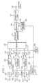
- Figure 1 is a block diagram showing a configuration for a digital signal recording apparatus according to a first example not forming part of the present invention. It is noted that the components having the same configuration or function will be denoted by the same reference numerals in the following description.
- the digital signal recording apparatus includes a mode setter 100 for setting the recording mode to be either one of a standard recording mode and a long-time recording mode.
- the mode setter 100 outputs mode information 101 indicating the set mode.
- the digital signal recording apparatus processes a luminance signal Y, a color difference signal (R-Y) and a color difference signal (B-Y) to be input through input terminals 102, 103 and 104 respectively. After these signals are variable-length coded, a video signal is output through an output terminal 122 by the digital signal recording apparatus.
- the digital signal recording apparatus further includes A/D converters 105, 106 and 107 and a sampling frequency setter 108.
- the inputs of the A/D converters 105, 106 and 107 are connected with the input terminals 102, 103 and 104, respectively.
- the A/D converters 105, 106 and 107 convert an analog signal into a digital signal.
- a clock 109 is supplied from the sampling frequency setter 108 to the A/D converter 105.
- the sampling frequency of the A/D converter 105 is set by the clock 109 and is variable. On the other hand, the sampling frequencies of the A/D converters 106 and 107 are fixed.
- the digital signal recording apparatus further includes: a delay circuit 112; line decimators 110 and 111; and switches 113, 114 and 115.
- the delay circuit 112 is connected with the output of the A/D converter 105, thereby delaying the luminance signal by a time corresponding to the processing time of the line decimators 110 and 111.
- the line decimator 110 is connected with the output of the A/D converter 106, and decimates the color difference signal (R-Y) on a line basis after limiting the vertical band of the color difference signal (R-Y) to one half.
- the line decimator 111 is connected with the output of the A/D converter 107, and decimates the color difference signal (B-Y) on a line basis after limiting the vertical band of the color difference signal (B-Y) to one half.
- the input of the switch 113 is connected with the output of the A/D converter 105 and the output of the delay circuit 112, thereby outputting either the output of the A/D converter 105 or the output of the delay circuit 112 in accordance with the mode information 101.
- the input of the switch 114 is connected with the output of the A/D converter 106 and the output of the line decimator 110, thereby outputting either the output of the A/D converter 106 or the output of the line decimator 110 in accordance with the mode information 101.
- the input of the switch 115 is connected with the output of the A/D converter 107 and the output of the line decimator 111, thereby outputting either the output of the A/D converter 107 or the output of the line decimator 111 in accordance with the mode information 101.
- the digital signal recording apparatus further includes: a blocker 116 ; an orthogonal transformer 117 ; a quantizer 118 ; a quantization controller 119 ; and a variable-length coder 121.
- the blocker 116 is connected with the outputs of the switches 113, 114 and 115, and forms a block consisting of 64 pixels, i.e., eight horizontal pixels ⁇ eight vertical lines, from the signals input in the order of the raster scanning in accordance with the mode information 101 , thereby outputting a signal on a block basis.
- the orthogonal transformer 117 performs a two-dimensional orthogonal transform on a block basis consisting of (8 ⁇ 8) pixels.
- the quantizer 118 quantizes the output of the orthogonal transformer 117 .
- the quantization step in the quantizer 118 is determined by the quantization information 120 output from the quantization controller 119.
- the quantization controller 119 determines the quantization step in the quantizer 118 in accordance with the mode information 101 so that the amount of the data after the high-efficiency coding becomes a predetermined amount or less.
- the variable-length coder 121 variable-length codes the output of the quantizer 118 .
- the variable-length coded video signal is output through an output terminal 122 .
- the mode setter 100 sets the mode information 101 to be "0" in the standard recording mode and "1" in the long-time recording mode.
- the selected mode information 101 is supplied to the sampling frequency setter 108 , the switches 113, 114 and 115 , the blocker 116 and the quantization controller 119 .
- the luminance signal Y and the color difference signals (R-Y) and (B-Y) input through the terminals 102, 103 and 104 are converted into digital signals by the A/D converters 105, 106 and 107, respectively.
- the sampling frequency setter 108 outputs a clock 109 having a different frequency to the A/D converter 105 in accordance with the mode information 101.
- the sampling frequency for the luminance signal in the A/D converter 105 is determined by the clock 109.
- the clock 109 is set so as to have a frequency of 13.5 MHz in the standard recording mode and a frequency of 10.125 MHz in the long-time recording mode.
- the sampling frequency for the luminance signal in the long-time recording mode is set to be three-quarters of the sampling frequency for the luminance signal in the standard recording mode.
- the sampling frequency for the color difference signals is always fixed at 3.375 MHz in both the modes.
- the switches 113, 114 and 115 are controlled to select the outputs of the A/D converters 105, 106 and 107.
- the switches 113, 114 and 115 are controlled to select the output of the delay circuit 112 and those of the line decimators 110 and 111. Therefore, the outputs of the A/D converters 105, 106 and 107 are input to the blocker 116 in the standard recording mode, while the outputs of the delay circuit 112 and the line decimators 110 and 111 are input to the blocker 116 in the long-time recording mode.
- Figure 2A shows the sampling number of a unit frame to be input to the blocker 116 in the standard recording mode.
- Figure 2B shows the sampling number of a unit frame to be input to the blocker 116 in the long-time recording mode.
- the blocker 116 blocks the luminance signal and the color difference signals which have been input in the order of the raster scanning.
- Each of the blocks consists of 64 pixels, i.e., eight horizontal pixels ⁇ eight vertical lines, and then outputs a signal on a five macro block basis.
- the macro block is herein composed of the blocks for the luminance signal and the blocks for the color difference signals which are located at the same position on the screen.
- FIG. 3 shows the macro blocks to be output from the blocker 116 as a unit (hereinafter, referred to as a "video segment") for the high-efficiency coding in the standard recording mode.
- one video segment consists of five macro blocks 300, 301, 302, 303 and 304 .
- Each of the macro blocks 300, 301, 302, 303 and 304 consists of six blocks, i.e., four luminance signal blocks, one R-Y color difference signal block and one B-Y color difference signal block. Therefore, one video segment consists of thirty blocks.
- Figure 4 shows the macro blocks to be output from the blocker 116 as a video segment in the long-time recording mode.
- one video segment consists of five macro blocks 400, 401, 402, 403 and 404.
- Each of the macro blocks 400, 401, 402, 403 and 404 consists of eight blocks, i.e., six luminance signal blocks, one R-Y color difference signal block and one R-Y color difference signal block. Therefore, one video segment consists of forty blocks.
- the number of the video segments per frame and the number of the macro blocks per frame in the long-time recording mode are one half as small as the number of the video segments per frame and the number of the macro blocks per frame in the standard recording mode, respectively.
- the data output from the blocker 116 on the video segment basis is input to the orthogonal transformer 117 and an (8 ⁇ 8) two-dimensional orthogonal transform is performed therein.
- the coefficient obtained by the two-dimensional orthogonal transform is quantized by the quantizer 118 .
- the quantization step in the quantizer 118 is determined by the quantization controller 119.
- the quantization controller 119 determines the quantization step so that the data amount after the data in one video segment has been coded becomes equal to or less than a predetermined data amount.
- the coefficients of the respective blocks are quantized at a predetermined number of quantization steps, the amount of the data to be generated during the variable-length coding is presumed, and the quantization steps are determined so that the data amount after the coding becomes a predetermined amount or less.
- the coefficients quantized at the determined quantization steps are variable-length coded based on a Huffman table by the variable-length coder 121 .
- the number of the blocks per video segment is 30 in the standard recording mode and 40 in the long-time recording mode.
- the amount of the coded data in one video segment is controlled to be equal in both the modes by the quantization controller 119 .
- the compression rate in the long-time recording mode becomes four-thirds of the compression rate in the standard recording mode.
- the data high-efficiency coded by the above-described method is output from the code-word output terminal 122 .
- a parity for an error correction coding is added to the coded signal if necessary, and then recorded on a recording medium.
- the sampling frequency of the A/D conversion for the luminance signal in the long-time recording mode is set to be three-quarters of the sampling frequency of the A/D conversion for the luminance signal in the standard recording mode; the lines are decimated with respect to the color difference signals, thereby reducing the data amount to two-thirds before the high-efficiency coding is performed; and the number of the blocks per video segment in the long-time recording mode is set to be four-thirds of the number of the blocks per video segment in the standard recording mode, thereby setting the compression rate in the long-time recording mode to be four-thirds of the compression rate in the standard recording mode, so that it is possible to reduce the amount of the data to be recorded in the long-time recording mode to be one half of the amount of the data to be recorded in the standard recording mode.
- FIG. 5 is a block diagram showing a configuration for a digital signal recording apparatus according to an example not forming part of the present invention.
- the digital signal recording apparatus of this example includes a digital filter 700 instead of the delay circuit 112 .
- the method of this example is different from the method of the first example in that the luminance signal is A/D converted and then the frequency components of the luminance signal in the high-pass band are restrained by using the digital filter 700 .
- Figure 6 is a graph showing the frequency characteristics of the luminance signal after the A/D conversion and those of the luminance signal after the digital filtering.
- the curve 800 indicates the characteristics of the luminance signal sampled at a frequency of 13.5 MHz in the standard recording mode; the curve 801 indicates the characteristics of the luminance signal sampled at a frequency of 10.125 MHz in the long-time recording mode; and the curve 802 indicates preferable characteristics of the luminance signal in the long-time recording mode to be obtained by restraining the characteristics indicated by the curve 801 in the high-pass band by using the digital filter 700 .
- the gain of the luminance signal in the standard recording mode is defined to be 0 dB at a frequency of 5.75 MHz or less, and -12 dB or less at a frequency of 6.75 MHz according to the standard REC601 (as indicated by the curve 800 ). Since the sampling frequency for the luminance signal in the long-time recording mode becomes three-quarters of the frequency in the standard recording mode, the gain of the luminance signal in the long-time recording mode becomes 0 dB at a frequency of 4.31 MHz or less and -12 dB or less at a frequency of 5.06 MHz according to the standard REC601 (as indicated by the curve 801 ).
- the compression of the data in the long-time recording mode is performed at a compression rate which is four-thirds of the compression rate in the standard recording mode. Therefore, unless the data is processed in an appropriate manner, a sufficient amount of codes cannot be assigned in the low to middle frequency regions considerably affecting the visual quality of the video unlike the standard recording mode, so that the quality of the video is degraded.
- the frequency components in the high-pass band of 5 MHz or more is sufficiently attenuated by using the digital filter 700, and the frequency components in the band of 4 to 5 MHz is also attenuated to a certain degree in order to facilitate the design of the filter 700.
- the codes in such an amount as not to considerably degrade the resolution can be assigned to the low to middle frequency regions.
- the specific characteristics of the digital filter 700 can be arbitrarily selected while examining the quality of the processed video.
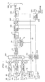
- Figure 7 is a block diagram showing a configuration for a digital signal recording apparatus according to an example of the present invention.
- the reference numerals denote as follows: 1000 is a simplified blocker; 1001 is an auxiliary data adder; 1002 is an error correction coder; 1003 is a recording coder; 1004 is a recording amplifier; 1005 is a recording head; 1006 is a magnetic tape; 1007 is an audio signal input terminal; 1008 is an audio signal coder; 1009 is a tape speed controller; and 1010 is a tape transporting motor.
- the operation of the digital signal recording apparatus of the example will be described. It is noted that the operations of the respective components denoted by 110 to 115 and 117 to 121 are the same as those of the components denoted by the same reference numerals in the second example.
- the digital filter 700 described in the third example is used for processing the luminance signal.
- the delay circuit 112 described in the first example can be used instead.
- Figure 8 shows an exemplary arrangement of a plurality of macro blocks in the long-time recording mode.
- the luminance signal per frame consists of 540 horizontal pixels ⁇ 480 vertical lines while one macro block consists of 24 horizontal pixels ⁇ 16 vertical lines.
- one frame is divided into 675 macro blocks, i.e., 22.5 horizontal macro blocks ⁇ 30 vertical macro blocks.
- the number of the horizontal pixels per frame is not N times as large as the number of the horizontal pixels per macro block, so that the macro block (MB44) at the right end has an elongate configuration in the vertical direction.
- Figure 9 is a block diagram showing a detailed configuration for the simplified blocker 1000 of this example.
- the simplified blocker 1000 includes: a memory 1202 ; a selector 1203 ; an address controller 1206 ; and a pseudo macro block detector 1207 .
- three kinds of digital video signals Y, R-Y and B-Y input from a video signal input terminal 1201 are input to the memory 1202 and the address controller 1206 .
- the address controller 1206 detects an effective pixel range based on the horizontal and vertical synchronization signals of the input video signals, thereby controlling the address so that the video signals input to the memory on the respective horizontal lines are read out in the order of the macro blocks.
- the video signals are output from the memory 1202 on a macro block basis.
- the macro blocks included in the input video signals output from the memory 1202 are herein referred to as "input macro blocks".
- the pseudo macro block detector 1207 When the address of the macro block at the right end in the horizontal direction within one frame, i.e., the region of the twelve pixels at the right end of Figure 11 , is output from the address controller 1206 , the pseudo macro block detector 1207 outputs a pseudo macro block detection signal to the selector 1203 .
- the selector 1203 When the pseudo macro block detection signal is not input to the selector 1203 , the selector 1203 outputs the input macro block via an output terminal 1205 .
- the selector 1203 when the pseudo macro block detection signal is input to the selector 1203 , the selector 1203 outputs a predetermined value via the output terminal 1205 .
- the macro block having the predetermined value output from the selector 1203 when the pseudo macro block is detected will be called a pseudo macro block herein.
- the macro block with a particular shape at the right end in Figure 8 is replaced by the pseudo macro block, so that it is not necessary to read the input video signal from the memory 1202 during the period. Therefore, no address generator and no memory region for storing the video signal are required for the macro block with this particular shape. As a result, even when the number of the horizontal or vertical effective pixels in one frame is not N times as large as the number of the horizontal or vertical effective pixels in one macro block, there is no need for providing an address generator or increasing the capacity of the memory.
- FIG. 10 an exemplary pseudo macro blocker (or the selector 1203 shown in Figure 9 ) will be described.
- the reference numerals denote as follows: 1301 is an input maoro block input section; 1302 is a 128 generating section; 1303 is a pseudo macro block detecting section; 1304 is a switch; and 1305 is a macro block output section.
- the switch 1304 shown in Figure 10 When the pseudo macro block detection signal is not input from the pseudo macro block detecting section 1303, the switch 1304 shown in Figure 10 outputs the input macro block input from the input macro block input section 1301 to the macro block output section 1305. On the other hand, when the pseudo macro block detection signal is input from the pseudo macro block detecting section 1303 , the switch 1304 outputs a value of 128 generated by the 128 generating section 1302 to the macro block output section 1305 . As a result, when the pseudo macro block is detected, the value of 128 is always output as the pixel value of the pseudo macro block.
- Figure 11 shows an exemplary configuration for the screen when such a pseudo macro block is used.
- the region for the pseudo macro block is indicated by the hatching at the right end in Figure 11 .
- all the data in the pseudo macro block region is reproduced at a pixel value of 128 , so that the region is recognized as a horizontal blanking region and causes no visual disturbance.
- the technique using a pseudo macro block of this example is applicable to any arbitrary macro block structure or frame structure.
- the pixel value in the pseudo macro block is not limited to 128 employed in this example, but an arbitrary value can be selected.
- the pixel values within the pseudo macro block can be varied in the respective small blocks.
- the pixel value in the pseudo macro block region can be replaced by an arbitrary value and then output during the reproducing operation, in the same manner as a coder.
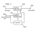
- FIG 12 is a block diagram showing a detailed configuration for the auxiliary data adder 1001 of this example.
- the auxiliary data adder 1001 includes: an auxiliary data generator 1501 ; an auxiliary data inserter 1502 ; and a controller 1503 .
- the digital data is input to the auxiliary data inserter 1502 via an input terminal 1500
- a signal to which the auxiliary data is inserted is output from the auxiliary data inserter 1502 via an output terminal 1504 .
- the mode information 101 is input to the auxiliary data generator 1501 and the controller 1503 via a mode information input terminal 1505 .
- the video date is assumed to be input via the input terminal 1500 and the amount of the information in the long-time recording mode is assumed to be one half of the amount of the information in the standard recording mode.
- the information is recorded by using ten tracks per frame in the standard recording mode and five tracks per frame in the long-time recording mode, for example.
- An auxiliary data is generated by the auxiliary data generator 1501 .
- the auxiliary data is inserted into the coded video data by the auxiliary data inserter 1502 .
- the position of the video data into which the auxiliary data is inserted is controlled by the controller 1503 .
- Figure 13A schematically shows the position on the recording track into which the auxiliary data is inserted.
- the auxiliary data is repeatedly and periodically inserted into the positions A and B from the head track of the frame. More specifically, the auxiliary data is inserted in the order of A ⁇ B ⁇ A ⁇ B ⁇ ...
- the recording operation is continuously performed on a track in the long-time recording mode immediately after the recording operation on the same track in the standard recording mode is finished.
- the mode information 101 input from the mode information input terminal 1505 is switched from "0" (for the standard recording mode) into "1" (for the long-time recording mode).
- the auxiliary data for the long-time recording mode generated by the auxiliary data generator 1501 is inserted by the auxiliary data inserter 1502 with the insertion position controlled by the controller 1503 .
- the auxiliary data is periodically inserted into the different positions from the head track of the frame.
- the controller 1503 controls the insertion at a period of two frames. More specifically, as shown in Figure 13B , the auxiliary data is inserted in the order of C ⁇ D ⁇ C ⁇ D ⁇ C in the recording start frame and in the order of D ⁇ C ⁇ D ⁇ C ⁇ D in the next frame. As a result, the period of the positions into which the auxiliary data is inserted is the same as that in the standard recording mode.
- the recording pattern obtained in this way is shown in Figure 13C .
- the period of the insertion positions of the auxiliary data is maintained in both of the portions where the video data is recorded in the standard recording node and in the portions where the video data is recorded in the long-time recording mode.
- the auxiliary data can be detected during the reproduction operation by commonly using a detector and detection timings for the standard recording mode, irrespective whether the video data is recorded in the standard recording mode or in the long-time recording mode.
- the video data is recorded by using ten tracks per frame in the standard recording mode and five tracks in the long-time recording mode.
- the data to be recorded is assumed to be a video data.
- a video signal, an audio signal or the like can be compressed by any arbitrary method such as a DCT, a DPCM or the like.
- a track may have any arbitrary contents.
- the auxiliary data principally consists of the information required for reproducing an audio data, a video data or the like. However, the auxiliary may have any arbitrary content.
- An appropriate error correction code is added by the error correction coder 1002 to the data to which the auxiliary data has been added in accordance with the mode information 101.
- FIG 14 is a block diagram showing a detailed configuration for the recording coder 1003 which is not part of the present invention.
- the reference numerals denote as follows: 1700 is a data input terminal; 1701 is a mode information input terminal; 1702 is an address adder; 1703 is a frame control signal generator; and 1704 is a recording data output terminal.
- 1700 is a data input terminal
- 1701 is a mode information input terminal
- 1702 is an address adder
- 1703 is a frame control signal generator
- 1704 is a recording data output terminal.
- the operation of the recording coder 1003 of this example will be described.
- the control can be performed on an n-frame basis in the same way.
- the frame control signal generator 1703 generates a one-frame control signal when the mode information 101 is "0" in order to synchronize the frames with each other on a one-frame basis.
- the frame control signal generator 1703 when the mode information 101 is "1", the frame control signal generator 1703 generates a two-frame control signal in order to synchronize the frames with each other on a two-frame basis.
- the two-frame control signal can be synchronized with the color frame period thereof.
- the processing of an audio data will be described.
- the audio signal input from an audio signal input terminal 1007 is an analog signal
- the audio signal is A/D converted and then processed by an audio signal coder 1008 .
- the audio signal input from the audio signal input terminal 1007 is a digital signal
- the audio signal is blocked by performing predetermined audio signal processings such as a filtering, a rearrangement, a compression and the like if necessary in accordance with the mode information 101 , so as to be output as an audio data.
- the blocked data is error correction coded by the error correction coder 1002 ; an address for recording is added to the data by the recording coder 1003 ; and the data is amplifies by the recording amplifier 1004 and then recorded on the magnetic tape 1006 by the recording head 1005 .
- the tape speed controller 1009 determines a tape transporting speed suitable for the respective modes in accordance with the mode information 101 and controls the tape transporting motor 1010 .
- the audio data is recorded on the respective tracks in the same recording pattern as that described in the conventional example.
- the tape transporting speed is different, the pattern to be actually formed on the tape possibly has a slightly different track angle.
- the sub-code data and the auxiliary data which are assembled on a one-field basis or on a one-frame basis can be assembled on a two-frame basis in accordance with the two-frame control signal.
- an address is composed of a frame address for identifying a frame, a track address provided at a period of two frames and a block address provided at a period of one track.
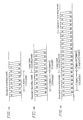
- the frame addresses and the track addresses can be arranged as shown in Figures 15A and 15B .
- the track address is begun with 0, and the same value is assigned to two adjacent tracks having different azimuths.
- the same result is obtained irrespective of how the values are assigned. That is to say, the assignment can be begun with any other value; the value can be changed in every track; and the value can increase or decrease.
- the recording pattern for a track shown in Figure 16 is employed. However, the same result can be obtained in any form such as the number of the sectors.
- an address is added after the error correction coding is performed. However, if the recording is performed in the order of the addition of an address, the error correction coding with respect to the address and the data, and generation of a parity, the same effects can be attained.
- n frames of the TV signal can be recorded on ten tracks, while in the case of recording a currently used TV signal having a system of 625 lines and 50 fields, the n frames of the TV signal can be recorded on twelve tracks.
- n can be 1 in the standard recording mode and n can be 2 in the long-time recording mode.
- the recording can be performed for a time longer than a conventional time.
- a recording apparatus with the same configuration in both the standard recording mode and the long-time recording mode, almost no circuits are required to be additionally provided except for the circuits necessary for a high compression.
- any method can be used for compressing a video signal and an audio signal.
Description
- The present invention relates to a digital signal recording apparatus for recording a digital signal such as an audio signal. More specifically, the present invention relates to a digital signal recording apparatus for performing a recording operation in a standard recording mode and a long-time recording mode in which information can be recorded on one and the same recording medium for a time longer than that of the standard recording mode. Such an apparatus is known from the document EP-A-0 556 816.
- In recent years, various recording and reproducing apparatuses have been remarkably developed in order to improve the quality of a video by using digital coding technologies. Under these circumstances, a digital video cassette recorder (VCR) is expected to be a next-generation VCR which is sure to replace a currently used analog VCR in the near future. In order to realize a home-use digital VCR, the information is required to be recorded in a smaller-sized cassette for a long time. Accordingly, it is indispensable to introduce high-efficiency coding technologies into such a digital VCR for reducing the amount of information of the digital video signal while preventing considerable degradation in the quality of the video. A standard format of the home-use digital VCR (DVCR) utilizing the high-efficiency coding technologies is published in the "Basic Specifications for Consumer-Use Digital VCR" by HD Digital VCR Conference in August 1993. This DVCR can record a currently used TV signal in compliance with a REC601 standard on a magnetic tape at a data rate of 25 Mbps.
- Hereinafter, the operation of such a DVCR will be briefly described. When the currently used TV signal to be input is an analog signal, the analog signal is A/D converted and then filtered so that the sampling ratio among a luminance (Y) signal, a first color difference (R-Y) signal and a second color difference (B-Y) signal becomes 4:1:1 in the horizontal direction. Needless to say, when the input TV signal is a digital signal, there is no need for the A/D conversion. Thereafter, the order of the signals is changed and a predetermined video signal processing such as a compression processing is performed depending upon the necessity, thereby outputting a video data. In this case, an important data, such as a data indicating whether the input video is to be reproduced in an NTSC mode or in a PAL mode, which is indispensable for reproducing the video data will be called an "auxiliary data". The auxiliary data is inserted into the video data. Thereafter, an error correction coding is performed and the video data is modulated by a modulator so as to be converted into a recording signal suitable for a magnetic recording. Then, the signal is recorded on a magnetic tape. According to the basic specifications for consumer-use digital VCR, a NTSC TV signal is recorded by dividing one frame into ten tracks.
- In a generally used DVCR, a track is composed of a predetermined number of sectors and gaps between adjacent sectors, and a sector is composed of a predetermined number of synch blocks, run-ups, guards and the like. Tracking information, an audio data, a video data, a sub-code data and the like are assigned in the respective sectors. An auxiliary data is assigned and inserted into the identical sector where the audio data and the video data are assigned.
- It is generally considered to be indispensable for a recording apparatus for recording a video signal to edit various data on a field basis or on a frame basis. Therefore, not only a video data and an audio data but also a sub-code data and an auxiliary data can be edited as a whole on a field basis or on a frame basis. In order to realize such an edition, a field address for identifying a field, a track address determined by regarding one field as a period, and a block address determined by regarding one track as a period are generally provided. Alternatively, a frame address for identifying a frame, a track address determined by regarding one frame as a period, and a block address determined by regarding one track as a period can also be provided.
- As described in Japanese Patent Application No. 6-38248 entitled "Digital Signal Recording and Reproducing Method", the auxiliary data is periodically recorded at respectively different positions in the respective tracks in order to eliminate the influence of a burst error, a scratch and the like on a magnetic tape and to obtain the data easily during a trick play reproduction.
- In a currently used VTR of a VHS system, a video data can be recorded in following two recording modes, i.e., a standard recording mode and a three-time-longer recording mode in which a video data can be recorded on one and the same tape for a time three times as long as the time in the standard recording mode. Therefore, in practically using a home-use DVCR, the video data is frequently required to be recorded in a long-time (e.g., three-time-longer) recording mode rather in the standard recording mode.
- A DVCR allowing for recording a data in a long-time recording mode by a high-efficiency coding technique is disclosed, for example, in Japanese Laid-Open Patent Publication No. 5-183869 entitled "Digital Video Signal Recording Apparatus". In the technique disclosed in the patent publication, the ratio of the sampling numbers for the luminance signal in the standard recording mode with respect to the long-time recording mode is set to be 3:2. However, if the sampling frequency for the luminance signal in the standard recording mode is 13.5 MHz, for example, then the luminance signal in the long-time recording mode has a frequency band of 9 MHz. As a result, the resolution obtained in the long-time recording mode becomes inferior to that obtained by a conventional analog S-VHS. In addition, according to the standard REC601, the sampling ratio among the luminance signal, the first color difference signal and the second color difference signal is set to be 4:1:1 in recording the currently used TV signal in the standard recording mode by using a home-use DVCR. In this case, if the sampling frequency for the luminance signal in the long-time recording mode is set to be two-thirds of the sampling frequency for the luminance signal in the standard recording mode, then the sampling ratio becomes (8/3) 1:1, so that it becomes very difficult to use a common circuit by way of a blocking or the like in both modes.
- In addition, in the case where a block having the same addresses as those of a block for the standard recording mode is used in the long-time recording mode, then a correct frame cannot be designated by a frame address. Furthermore, if a signal for the standard recording mode and a signal for the long-time recording mode are tried to be continuously recorded on one and the same tape by inserting an auxiliary data into a frame by beginning with the position of the head track of the frame for both the signals, then the auxiliary data can not be inserted periodically. As a result, an error is likely to be caused in detecting the auxiliary data immediately after scanning the boundary between the recording region for a standard recording mode and the recording region for a long-time recording mode during the reproducing operation, and an algorism for detecting the position of the auxiliary data becomes more complicated, so that the size of the circuit becomes disadvantageously increased and the delay in the detection time is increased.
- It cannot be identified whether the reproduced data is recorded in the standard recording mode or in the long-time recording mode until the contents of the auxiliary data are examined. Therefore, in the case where detection errors are successively caused in a trick play reproduction, in particular, the reproduction processing is likely to be performed by mistaking a signal recorded in the long-time recording mode for a signal recorded in the standard recording mode, and a large defect is possibly generated in the video reproduced on a screen.
- Recently, as well as the currently used standard TV signal, a HDTV signal and a signal for a 16:9 wide screen TV have been more and more practically used. Therefore, a home-use DVTR allowing for recording the plural kinds of TV signals in common will be required in the near future. It is possible to commonly perform the signal processing and use the same recording head between the format for recording the standard TV signal and the format for recording the HDTV signal after the variable-length coding has been performed. However, it is difficult to commonly use the other portions of the circuit, because the number of the blocks per segment of the currently used TV signal, i.e., 6 blocks × 5 = 30, is different from the number of the blocks per segment of the HDTV signal, i.e., 8 blocks × 5 = 40. If independent circuits are provided for the respective TV signals, then the cost of the apparatus is adversely increased, so that it becomes very difficult to use such an apparatus as a home-use apparatus.
- According to the present invention, a digital signal recording apparatus for recording a video signal on a recording medium is provided, as defined in the claims.
- In a digital signal recording apparatus according to the present invention, it is possible to simplify the high efficiency coding processing in the long-time recording mode. Even when the signals in different recording modes are recorded on an identical recording medium, the auxiliary data can be inserted periodically. As a result, it is possible to prevent an error in detecting the auxiliary data in the long-time recording mode. Moreover, in order to implement an apparatus having such a configuration, it is not necessary to considerably increase the size of the circuit. Therefore, the recording apparatus of this invention can attain much practical effect.
- Thus, the invention described herein makes possible the advantage of providing a digital signal recording apparatus allowing for recording a digital data in a long-time recording mode in which the data can be recorded on a recording medium for a time longer than that of the standard recording mode.
- This and other advantages of the present invention will become apparent to those skilled in the art upon reading and understanding the following detailed description with reference to the accompanying figures.
-
- Figure 1 is a block diagram showing a configuration for a digital signal recording apparatus according to an embodiment not forming part of the present invention.
- Figure 2A is a schematic diagram showing a sampling number per frame in the standard recording mode.
- Figure 2B is a schematic diegram showing a sampling number per frame in the long-time recording mode.
- Figure 3 is a schematic diagram showing macro blocks composing a video segment in the standard recording mode.
- Figure 4 is a schematic diagram showing macro blocks composing a video segment in the long-time recording mode.
- Figure 5 is a block diagram showing a configuration for a digital signal recording apparatus according to an embodiment not forming part of the present invention.
- Figure 6 is a graph showing the characteristics of the luminance signal when the luminance signal is input to a blocker.
- Figure 7 is a block diagram showing a configuration for a digital signal recording apparatus according to a preferred embodiment of the present invention.
- Figure 8 is a schematic diagram showing an arrangement of the macro blocks in the long-time recording mode.
- Figure 9 is a block diagram showing a configuration for a simplified blocker.
- Figure 10 is a block diagram showing a configuration for a selector.
- Figure 11 is a schematic diagram showing a configuration for a screen on which the video signal recorded in the long-time recording mode is reproduced.
- Figure 12 is a block diagram showing a configuration for an auxiliary data adder.
- Figure 13A is a schematic diagram showing a track pattern in the case where the data is recorded in the standard recording mode.
- Figure 13B is a schematic diagram showing a track pattern in the case where the data is recorded in the long-time recording mode immediately after the data has been recorded in the standard recording mode.
- Figure 13C is a schematic diagram showing a track pattern in the case where the data is recorded in the standard recording mode immediately after the data has been recorded in the long-time recording mode.
- Figure 14 is a schematic diagram showing a configuration for a recording coder not forming part of the present invention.
- Figure 15A is a schematic diagram showing an arrangement of the addresses in the standard recording mode.
- Figure 15B is a schematic diagram showing an arrangement of the addresses in the long-time recording mode.
- Figure 16 is a schematic diagram showing a recording pattern for a conventional recording apparatus.
-
- Hereinafter, the present invention will be described by way of illustrative examples with reference to the accompanying drawings.
- Figure 1 is a block diagram showing a configuration for a digital signal recording apparatus according to a first example not forming part of the present invention. It is noted that the components having the same configuration or function will be denoted by the same reference numerals in the following description.
- The digital signal recording apparatus includes a
mode setter 100 for setting the recording mode to be either one of a standard recording mode and a long-time recording mode. Themode setter 100outputs mode information 101 indicating the set mode. In accordance with themode information 101, the digital signal recording apparatus processes a luminance signal Y, a color difference signal (R-Y) and a color difference signal (B-Y) to be input throughinput terminals output terminal 122 by the digital signal recording apparatus. - The digital signal recording apparatus further includes A/
D converters sampling frequency setter 108. The inputs of the A/D converters input terminals D converters clock 109 is supplied from thesampling frequency setter 108 to the A/D converter 105. The sampling frequency of the A/D converter 105 is set by theclock 109 and is variable. On the other hand, the sampling frequencies of the A/D converters - The digital signal recording apparatus further includes: a
delay circuit 112;line decimators delay circuit 112 is connected with the output of the A/D converter 105, thereby delaying the luminance signal by a time corresponding to the processing time of the line decimators 110 and 111. Theline decimator 110 is connected with the output of the A/D converter 106, and decimates the color difference signal (R-Y) on a line basis after limiting the vertical band of the color difference signal (R-Y) to one half. Theline decimator 111 is connected with the output of the A/D converter 107, and decimates the color difference signal (B-Y) on a line basis after limiting the vertical band of the color difference signal (B-Y) to one half. The input of theswitch 113 is connected with the output of the A/D converter 105 and the output of thedelay circuit 112, thereby outputting either the output of the A/D converter 105 or the output of thedelay circuit 112 in accordance with themode information 101. The input of theswitch 114 is connected with the output of the A/D converter 106 and the output of theline decimator 110, thereby outputting either the output of the A/D converter 106 or the output of theline decimator 110 in accordance with themode information 101. The input of theswitch 115 is connected with the output of the A/D converter 107 and the output of theline decimator 111, thereby outputting either the output of the A/D converter 107 or the output of theline decimator 111 in accordance with themode information 101. - The digital signal recording apparatus further includes: a
blocker 116; anorthogonal transformer 117; aquantizer 118; aquantization controller 119; and a variable-length coder 121. Theblocker 116 is connected with the outputs of theswitches mode information 101, thereby outputting a signal on a block basis. Theorthogonal transformer 117 performs a two-dimensional orthogonal transform on a block basis consisting of (8 × 8) pixels. Thequantizer 118 quantizes the output of theorthogonal transformer 117. The quantization step in thequantizer 118 is determined by thequantization information 120 output from thequantization controller 119. Thequantization controller 119 determines the quantization step in thequantizer 118 in accordance with themode information 101 so that the amount of the data after the high-efficiency coding becomes a predetermined amount or less. The variable-length coder 121 variable-length codes the output of thequantizer 118. The variable-length coded video signal is output through anoutput terminal 122. - Hereinafter, the operation of the digital signal recording apparatus of this example having the above configuration will be described.
- The
mode setter 100 sets themode information 101 to be "0" in the standard recording mode and "1" in the long-time recording mode. The selectedmode information 101 is supplied to thesampling frequency setter 108, theswitches blocker 116 and thequantization controller 119. - The luminance signal Y and the color difference signals (R-Y) and (B-Y) input through the
terminals D converters sampling frequency setter 108 outputs aclock 109 having a different frequency to the A/D converter 105 in accordance with themode information 101. The sampling frequency for the luminance signal in the A/D converter 105 is determined by theclock 109. Theclock 109 is set so as to have a frequency of 13.5 MHz in the standard recording mode and a frequency of 10.125 MHz in the long-time recording mode. That is to say, the sampling frequency for the luminance signal in the long-time recording mode is set to be three-quarters of the sampling frequency for the luminance signal in the standard recording mode. The sampling frequency for the color difference signals is always fixed at 3.375 MHz in both the modes. - When the
mode information 101 is set to be "0", theswitches D converters mode information 101 is set to be "1", theswitches delay circuit 112 and those of the line decimators 110 and 111. Therefore, the outputs of the A/D converters blocker 116 in the standard recording mode, while the outputs of thedelay circuit 112 and the line decimators 110 and 111 are input to theblocker 116 in the long-time recording mode. - Figure 2A shows the sampling number of a unit frame to be input to the
blocker 116 in the standard recording mode. As shown in Figure 2A, the sampling number per frame in the standard recording mode is: 720 pixels × 480 lines + 180 pixels × 480 lines × 2 = 518400 samples/frame. - Figure 2B shows the sampling number of a unit frame to be input to the
blocker 116 in the long-time recording mode. As shown in Figure 2B, the sampling number per frame in the long-time recording mode is: 540 pixels × 480 lines + 180 pixels × 240 lines × 2 = 345600 samples/frame. Accordingly, the total number of the samples in the long-time recording mode is two-thirds of the sampling number in the standard recording mode. - The
blocker 116 blocks the luminance signal and the color difference signals which have been input in the order of the raster scanning. Each of the blocks consists of 64 pixels, i.e., eight horizontal pixels × eight vertical lines, and then outputs a signal on a five macro block basis. The macro block is herein composed of the blocks for the luminance signal and the blocks for the color difference signals which are located at the same position on the screen. - Figure 3 shows the macro blocks to be output from the
blocker 116 as a unit (hereinafter, referred to as a "video segment") for the high-efficiency coding in the standard recording mode. In this example, one video segment consists of fivemacro blocks macro blocks - Figure 4 shows the macro blocks to be output from the
blocker 116 as a video segment in the long-time recording mode. In this example, one video segment consists of fivemacro blocks macro blocks - The data output from the
blocker 116 on the video segment basis is input to theorthogonal transformer 117 and an (8 × 8) two-dimensional orthogonal transform is performed therein. The coefficient obtained by the two-dimensional orthogonal transform is quantized by thequantizer 118. The quantization step in thequantizer 118 is determined by thequantization controller 119. Thequantization controller 119 determines the quantization step so that the data amount after the data in one video segment has been coded becomes equal to or less than a predetermined data amount. That is to say, the coefficients of the respective blocks are quantized at a predetermined number of quantization steps, the amount of the data to be generated during the variable-length coding is presumed, and the quantization steps are determined so that the data amount after the coding becomes a predetermined amount or less. The coefficients quantized at the determined quantization steps are variable-length coded based on a Huffman table by the variable-length coder 121. - As described referring to Figures 3 and 4, the number of the blocks per video segment is 30 in the standard recording mode and 40 in the long-time recording mode. On the other hand, the amount of the coded data in one video segment is controlled to be equal in both the modes by the
quantization controller 119. As a result, the compression rate in the long-time recording mode becomes four-thirds of the compression rate in the standard recording mode. - The data high-efficiency coded by the above-described method is output from the code-
word output terminal 122. A parity for an error correction coding is added to the coded signal if necessary, and then recorded on a recording medium. - As is apparent from the foregoing description, according to the method of this example, the sampling frequency of the A/D conversion for the luminance signal in the long-time recording mode is set to be three-quarters of the sampling frequency of the A/D conversion for the luminance signal in the standard recording mode; the lines are decimated with respect to the color difference signals, thereby reducing the data amount to two-thirds before the high-efficiency coding is performed; and the number of the blocks per video segment in the long-time recording mode is set to be four-thirds of the number of the blocks per video segment in the standard recording mode, thereby setting the compression rate in the long-time recording mode to be four-thirds of the compression rate in the standard recording mode, so that it is possible to reduce the amount of the data to be recorded in the long-time recording mode to be one half of the amount of the data to be recorded in the standard recording mode.
- Figure 5 is a block diagram showing a configuration for a digital signal recording apparatus according to an example not forming part of the present invention. The digital signal recording apparatus of this example includes a
digital filter 700 instead of thedelay circuit 112. - The method of this example is different from the method of the first example in that the luminance signal is A/D converted and then the frequency components of the luminance signal in the high-pass band are restrained by using the
digital filter 700. - Figure 6 is a graph showing the frequency characteristics of the luminance signal after the A/D conversion and those of the luminance signal after the digital filtering. In Figure 6, the
curve 800 indicates the characteristics of the luminance signal sampled at a frequency of 13.5 MHz in the standard recording mode; thecurve 801 indicates the characteristics of the luminance signal sampled at a frequency of 10.125 MHz in the long-time recording mode; and thecurve 802 indicates preferable characteristics of the luminance signal in the long-time recording mode to be obtained by restraining the characteristics indicated by thecurve 801 in the high-pass band by using thedigital filter 700. - The gain of the luminance signal in the standard recording mode is defined to be 0 dB at a frequency of 5.75 MHz or less, and -12 dB or less at a frequency of 6.75 MHz according to the standard REC601 (as indicated by the curve 800). Since the sampling frequency for the luminance signal in the long-time recording mode becomes three-quarters of the frequency in the standard recording mode, the gain of the luminance signal in the long-time recording mode becomes 0 dB at a frequency of 4.31 MHz or less and -12 dB or less at a frequency of 5.06 MHz according to the standard REC601 (as indicated by the curve 801).
- However, as described in the first example, the compression of the data in the long-time recording mode is performed at a compression rate which is four-thirds of the compression rate in the standard recording mode. Therefore, unless the data is processed in an appropriate manner, a sufficient amount of codes cannot be assigned in the low to middle frequency regions considerably affecting the visual quality of the video unlike the standard recording mode, so that the quality of the video is degraded. In order to prevent such a degradation, the frequency components in the high-pass band of 5 MHz or more is sufficiently attenuated by using the
digital filter 700, and the frequency components in the band of 4 to 5 MHz is also attenuated to a certain degree in order to facilitate the design of thefilter 700. As a result, the codes in such an amount as not to considerably degrade the resolution can be assigned to the low to middle frequency regions. The specific characteristics of thedigital filter 700 can be arbitrarily selected while examining the quality of the processed video. - As described above, according to the method of this example, by sufficiently attenuating the frequency components of the luminance signal in the high-pass band in the long-time recording mode, it is possible to prevent a considerable degradation of the quality of the video during a coding processing.
- Figure 7 is a block diagram showing a configuration for a digital signal recording apparatus according to an example of the present invention. In Figure 7, the reference numerals denote as follows: 1000 is a simplified blocker; 1001 is an auxiliary data adder; 1002 is an error correction coder; 1003 is a recording coder; 1004 is a recording amplifier; 1005 is a recording head; 1006 is a magnetic tape; 1007 is an audio signal input terminal; 1008 is an audio signal coder; 1009 is a tape speed controller; and 1010 is a tape transporting motor.
- Hereinafter, the operation of the digital signal recording apparatus of the example will be described. It is noted that the operations of the respective components denoted by 110 to 115 and 117 to 121 are the same as those of the components denoted by the same reference numerals in the second example. In this example, the
digital filter 700 described in the third example is used for processing the luminance signal. Alternatively, thedelay circuit 112 described in the first example can be used instead. - Figure 8 shows an exemplary arrangement of a plurality of macro blocks in the long-time recording mode. In this example, the luminance signal per frame consists of 540 horizontal pixels × 480 vertical lines while one macro block consists of 24 horizontal pixels × 16 vertical lines. Accordingly, one frame is divided into 675 macro blocks, i.e., 22.5 horizontal macro blocks × 30 vertical macro blocks. In this case the number of the horizontal pixels per frame is not N times as large as the number of the horizontal pixels per macro block, so that the macro block (MB44) at the right end has an elongate configuration in the vertical direction.
- In the case where such elongate macro blocks as those shown in Figure 8 exist, a conventional method requires a larger number of line memories as compared with the case of processing ordinary macro blocks.
- However, according to the method of this example, it is possible to simplify the blocking process by using a
simplified blocker 1000, and prevent the number of the circuits to be used. - Figure 9 is a block diagram showing a detailed configuration for the
simplified blocker 1000 of this example. As shown in Figure 9, thesimplified blocker 1000 includes: amemory 1202; aselector 1203; anaddress controller 1206; and a pseudomacro block detector 1207. - As shown in Figure 9, three kinds of digital video signals Y, R-Y and B-Y input from a video
signal input terminal 1201 are input to thememory 1202 and theaddress controller 1206. Theaddress controller 1206 detects an effective pixel range based on the horizontal and vertical synchronization signals of the input video signals, thereby controlling the address so that the video signals input to the memory on the respective horizontal lines are read out in the order of the macro blocks. As a result, the video signals are output from thememory 1202 on a macro block basis. The macro blocks included in the input video signals output from thememory 1202 are herein referred to as "input macro blocks". - When the address of the macro block at the right end in the horizontal direction within one frame, i.e., the region of the twelve pixels at the right end of Figure 11, is output from the
address controller 1206, the pseudomacro block detector 1207 outputs a pseudo macro block detection signal to theselector 1203. When the pseudo macro block detection signal is not input to theselector 1203, theselector 1203 outputs the input macro block via anoutput terminal 1205. On the other hand, when the pseudo macro block detection signal is input to theselector 1203, theselector 1203 outputs a predetermined value via theoutput terminal 1205. The macro block having the predetermined value output from theselector 1203 when the pseudo macro block is detected will be called a pseudo macro block herein. - In this example, the macro block with a particular shape at the right end in Figure 8 is replaced by the pseudo macro block, so that it is not necessary to read the input video signal from the
memory 1202 during the period. Therefore, no address generator and no memory region for storing the video signal are required for the macro block with this particular shape. As a result, even when the number of the horizontal or vertical effective pixels in one frame is not N times as large as the number of the horizontal or vertical effective pixels in one macro block, there is no need for providing an address generator or increasing the capacity of the memory. - Next, referring to Figure 10, an exemplary pseudo macro blocker (or the
selector 1203 shown in Figure 9) will be described. In Figure 10, the reference numerals denote as follows: 1301 is an input maoro block input section; 1302 is a 128 generating section; 1303 is a pseudo macro block detecting section; 1304 is a switch; and 1305 is a macro block output section. - When the pseudo macro block detection signal is not input from the pseudo macro
block detecting section 1303, theswitch 1304 shown in Figure 10 outputs the input macro block input from the input macroblock input section 1301 to the macroblock output section 1305. On the other hand, when the pseudo macro block detection signal is input from the pseudo macroblock detecting section 1303, theswitch 1304 outputs a value of 128 generated by the 128generating section 1302 to the macroblock output section 1305. As a result, when the pseudo macro block is detected, the value of 128 is always output as the pixel value of the pseudo macro block. - By using such a configuration, all the pixel values within the pseudo macro block are fixed at 128, so that the video coding considerably reduces the amount of the data. Therefore, it is possible to assign a code-word data in other input macro blocks to a part of the code-word region to which the pseudo macro block is assigned, thereby reducing the compression rate of the input macro block and improving the quality of the reproduced video.
- Consequently, in this example, by setting the pixel value of the pseudo macro block to be constant, it is possible to improve the quality of the reproduced video in the input macro block.
- Figure 11 shows an exemplary configuration for the screen when such a pseudo macro block is used. The region for the pseudo macro block is indicated by the hatching at the right end in Figure 11. In Figure 11, all the data in the pseudo macro block region is reproduced at a pixel value of 128, so that the region is recognized as a horizontal blanking region and causes no visual disturbance.
- The technique using a pseudo macro block of this example is applicable to any arbitrary macro block structure or frame structure. The pixel value in the pseudo macro block is not limited to 128 employed in this example, but an arbitrary value can be selected. The pixel values within the pseudo macro block can be varied in the respective small blocks.
- In a reproducing apparatus to which the
simplified blocker 1000 is applied, the pixel value in the pseudo macro block region can be replaced by an arbitrary value and then output during the reproducing operation, in the same manner as a coder. - Figure 12 is a block diagram showing a detailed configuration for the
auxiliary data adder 1001 of this example. As shown in Figure 12, theauxiliary data adder 1001 includes: anauxiliary data generator 1501; anauxiliary data inserter 1502; and acontroller 1503. The digital data is input to theauxiliary data inserter 1502 via aninput terminal 1500, and a signal to which the auxiliary data is inserted is output from theauxiliary data inserter 1502 via anoutput terminal 1504. Themode information 101 is input to theauxiliary data generator 1501 and thecontroller 1503 via a modeinformation input terminal 1505. - In this example, the video date is assumed to be input via the
input terminal 1500 and the amount of the information in the long-time recording mode is assumed to be one half of the amount of the information in the standard recording mode. In this case, the information is recorded by using ten tracks per frame in the standard recording mode and five tracks per frame in the long-time recording mode, for example. - First, a case where the recording operation is performed in the standard recording mode will be described. An auxiliary data is generated by the
auxiliary data generator 1501. The auxiliary data is inserted into the coded video data by theauxiliary data inserter 1502. The position of the video data into which the auxiliary data is inserted is controlled by thecontroller 1503. - Figure 13A schematically shows the position on the recording track into which the auxiliary data is inserted. As shown in Figure 13A, the auxiliary data is repeatedly and periodically inserted into the positions A and B from the head track of the frame. More specifically, the auxiliary data is inserted in the order of A→B→A→B→ ...
- Next, a case where the recording operation is continuously performed on a track in the long-time recording mode immediately after the recording operation on the same track in the standard recording mode is finished. In this case, when the video data for the long-time recording mode is input, the
mode information 101 input from the modeinformation input terminal 1505 is switched from "0" (for the standard recording mode) into "1" (for the long-time recording mode). Thereafter, the auxiliary data for the long-time recording mode generated by theauxiliary data generator 1501 is inserted by theauxiliary data inserter 1502 with the insertion position controlled by thecontroller 1503. - In the same way as in the standard recording mode, the auxiliary data is periodically inserted into the different positions from the head track of the frame. In the long-time recording mode, since the number of the recording tracks per frame is 2n + 1 (n = 1, 2, ...; in this example, n = 2), the
controller 1503 controls the insertion at a period of two frames. More specifically, as shown in Figure 13B, the auxiliary data is inserted in the order of C→D→C→D→C in the recording start frame and in the order of D→C→D→C→D in the next frame. As a result, the period of the positions into which the auxiliary data is inserted is the same as that in the standard recording mode. - On the other hand, in the case where the recording operation is continuously performed on a track in the standard recording mode immediately after the recording operation on the same track in the long-time recording mode is finished, the start position of the standard recording is controlled by the
controller 1503 so that the standard recording is started immediately after a frame in which the last insertion position of the auxiliary data is the position C by using a number m of frames (m = 2, 4, 6, ...; in this example m = 2) for the long-time recording mode as an edition unit. The recording pattern obtained in this way is shown in Figure 13C. As shown in Figure 13C, the period of the insertion positions of the auxiliary data is maintained in both of the portions where the video data is recorded in the standard recording node and in the portions where the video data is recorded in the long-time recording mode. - As described above, according to the method of this example, by controlling the insertion positions of the auxiliary data and the timing for switching the recording modes, it is possible to maintain the period of the insertion positions of the auxiliary data even when the video data is recorded on one and the same tape-shaped recording medium in both modes. As a result, the auxiliary data can be detected during the reproduction operation by commonly using a detector and detection timings for the standard recording mode, irrespective whether the video data is recorded in the standard recording mode or in the long-time recording mode.
- In this example, the video data is recorded by using ten tracks per frame in the standard recording mode and five tracks in the long-time recording mode. However, the number of the tracks to be used is not limited thereto. Since the amount of information to be recorded in the long-time recording mode is 1/m (m = 2, 4, 6, ...) as small as the amount of the information to be recorded in the standard recording mode, the number of the recording tracks in the long-time recording mode can be generally expressed by 2n + 1, while the number of the recording tracks in the standard recording mode can be generally expressed by m × (2n + 1). It is obvious that the same effects can be generally attained irrespective of the number of the recording tracks to be used.
- In this example, the data to be recorded is assumed to be a video data. However, it is obvious that the same effects can be attained if other kinds of data such as an audio data is recorded. A video signal, an audio signal or the like can be compressed by any arbitrary method such as a DCT, a DPCM or the like.
- The detailed contents of a track have not specifically been mentioned in the above description. A track may have any arbitrary contents. The auxiliary data principally consists of the information required for reproducing an audio data, a video data or the like. However, the auxiliary may have any arbitrary content.
- An appropriate error correction code is added by the
error correction coder 1002 to the data to which the auxiliary data has been added in accordance with themode information 101. - Figure 14 is a block diagram showing a detailed configuration for the
recording coder 1003 which is not part of the present invention. In Figure 14, the reference numerals denote as follows: 1700 is a data input terminal; 1701 is a mode information input terminal; 1702 is an address adder; 1703 is a frame control signal generator; and 1704 is a recording data output terminal. Hereinafter, the operation of therecording coder 1003 of this example will be described. In this example, it is assumed that a video data is input, and that a one-frame control is performed in the standard recording mode while a two-frame control is performed in the long-time recording mode. However, the control can be performed on an n-frame basis in the same way. - The frame
control signal generator 1703 generates a one-frame control signal when themode information 101 is "0" in order to synchronize the frames with each other on a one-frame basis. On the other hand, when themode information 101 is "1", the framecontrol signal generator 1703 generates a two-frame control signal in order to synchronize the frames with each other on a two-frame basis. In the case where the input video signal is a composite signal, the two-frame control signal can be synchronized with the color frame period thereof. - Referring back to Figure 7, the processing of an audio data will be described. When the audio signal input from an audio
signal input terminal 1007 is an analog signal, the audio signal is A/D converted and then processed by anaudio signal coder 1008. Needless to say, when the audio signal input from the audiosignal input terminal 1007 is a digital signal, there is no need for performing the A/D conversion. The audio signal is blocked by performing predetermined audio signal processings such as a filtering, a rearrangement, a compression and the like if necessary in accordance with themode information 101, so as to be output as an audio data. Thereafter, the blocked data is error correction coded by theerror correction coder 1002; an address for recording is added to the data by therecording coder 1003; and the data is amplifies by therecording amplifier 1004 and then recorded on themagnetic tape 1006 by therecording head 1005. - The
tape speed controller 1009 determines a tape transporting speed suitable for the respective modes in accordance with themode information 101 and controls thetape transporting motor 1010. - In this case, the audio data is recorded on the respective tracks in the same recording pattern as that described in the conventional example. However, since the tape transporting speed is different, the pattern to be actually formed on the tape possibly has a slightly different track angle.
- The sub-code data and the auxiliary data which are assembled on a one-field basis or on a one-frame basis can be assembled on a two-frame basis in accordance with the two-frame control signal. In order to use the arrangement of these data in the same way as the data recorded by a conventional recording apparatus, an address is composed of a frame address for identifying a frame, a track address provided at a period of two frames and a block address provided at a period of one track. For example, in a recording apparatus in which one frame is composed of ten tracks, the frame addresses and the track addresses can be arranged as shown in Figures 15A and 15B. In Figures 15A and 15B, the track address is begun with 0, and the same value is assigned to two adjacent tracks having different azimuths. The same result is obtained irrespective of how the values are assigned. That is to say, the assignment can be begun with any other value; the value can be changed in every track; and the value can increase or decrease. In this example, the recording pattern for a track shown in Figure 16 is employed. However, the same result can be obtained in any form such as the number of the sectors. According to the present invention, an address is added after the error correction coding is performed. However, if the recording is performed in the order of the addition of an address, the error correction coding with respect to the address and the data, and generation of a parity, the same effects can be attained.
- In the case of recording a currently used TV signal having a system of 525 lines and 60 fields, the n frames of the TV signal can be recorded on ten tracks, while in the case of recording a currently used TV signal having a system of 625 lines and 50 fields, the n frames of the TV signal can be recorded on twelve tracks. In such a case, n can be 1 in the standard recording mode and n can be 2 in the long-time recording mode.
- As described above, according to the method of this example, by compressing a video signal at a rate n times as high as a conventional rate and using a track address for designating a track at a period of n frames, the recording can be performed for a time longer than a conventional time. In addition, by commonly using a recording apparatus with the same configuration in both the standard recording mode and the long-time recording mode, almost no circuits are required to be additionally provided except for the circuits necessary for a high compression. Furthermore, any method can be used for compressing a video signal and an audio signal.
Claims (2)
- A digital signal recording apparatus for recording a digital signal on a recording medium, comprising:characterized in that the auxiliary data adding means (1001) comprises:a mode setting means (100) for setting a recording mode, the recording mode being one of a standard recording mode and a long-time recording mode having a longer recording time than that of the standard recording mode;a coding means (1003) for coding the digital signal so as to obtain data having a data amount corresponding to the recording mode set by the mode setting means, the data amount when the selected recording mode is the long-time recording mode being smaller than the data amount when the selected recording mode is the standard recording mode;a recording means (1005) for recording the data to which an auxiliary data is added, on the recording medium;an auxiliary data adding means (1001) for adding auxiliary data, which is required for reproduction of the recorded digital signal, to the data coded by the coding means (1003) in accordance with the recording mode set by the mode setting means (100), the auxiliary data including a first auxiliary data, a second auxiliary data, a third auxiliary data and a fourth auxiliary data,whereinan auxiliary data generating means (1501) for generating the first auxiliary data and the second auxiliary data when the selected recording mode is the standard recording mode, and for generating the third auxiliary data and the fourth auxiliary data when the selected recording mode is the long-time recording mode;a control means (1503) for generating a first control signal indicating a first insertion position (A) and a second insertion positions (B) when the selected recording mode is the standard recording mode, and for generating a second control signal indicating a third insertion position (C) and a fourth insertion position (D) when the selected recording mode is the long-time recording mode; andan auxiliary data inserting means (1502) for inserting the first auxiliary data into the coded data at the first insertion position (A) and the second auxiliary data into the coded signal at the second insertion position (B) when the selected recording mode is the standard recording mode, and for inserting the third auxiliary data into the coded data at the third insertion position (C) and the fourth auxiliary data into the coded data at the fourth insertion position (D) when the selected recording mode is the long-time recording mode the first and second insertion positions (A;B) being indicated by the first control signal and the third and fourth insertion positions being indicated by the second control signal,
when the selected recording mode is the standard recording mode, the first insertion position (A) and the second insertion position (B) are controlled by the control means (1503) so that the first auxiliary data and the second auxiliary data are alternately inserted into a plurality of tracks at the first insertion position (A) and the second insertion position (B), respectively, so that the first insertion position (A) is formed at a first end of a first type of track and the second insertion position (B) is formed at a second end of a second type of track which is adjacent to the first type of track, the second end being opposite to the first end, such that the first and second auxiliary data are inserted in a first periodic track pattern of the first and second insertion positions (A;B) and wherein a first edition unit comprises a predetermined number of tracks,
when the selected recording mode is the long-time recording mode, the third insertion position (C) and the fourth insertion position (D) are controlled by the control means (1503) so that the third auxiliary data and the fourth auxiliary data are alternately inserted into a plurality of tracks at the third insertion position (C) and the fourth insertion position (D), respectively, so that the third insertion position (C) is formed at a third end of a third type of track and the fourth insertion position (D) is formed at a fourth end of a fourth type of track which is adjacent to the third type of track, the fourth end being opposite to the third end, such that the third and fourth auxiliary data are inserted in a second periodic track pattern of the third and fourth insertion positions (C;D) and wherein a second edition unit comprises a predetermined number of tracks,
the first periodic track pattern of the first and second insertions positions (A;B) is substantially the same as the second periodic track pattern of the third and fourth insertion positions (C;D),
when the second type of track is adjacent to the third type of track in response to a mode change from the standard recording mode to the long-time recording mode at the end of the first edition unit, the second insertion position (B) and the third insertion position (C) are controlled by the control means (1503) so that the second end of the second type of track is opposite to the third end of the third type of track; and
when the fourth type of track is adjacent to the first type of track in response to a mode change from the long-time recording mode to the standard recording mode at the end of the second edition unit, the fourth insertion position (D) and the first insertion position (A) are controlled by the control means (1503) so that the fourth end of the fourth type of track is opposite to the first end of the first type of track. - A digital signal recording apparatus according to claim 1, wherein the recording means (1005) divides and records the data to which the auxiliary data is added on m x (2n+1) tracks, where m is 2, 4, 6,... and n is 1, 2, 3,..., on the recording medium when the selected recording mode is the standard recording mode, and the recording means divides and records the data to which the auxiliary data is added on 2n+1 tracks on the recording medium when the selected recording mode is the long-time recording mode.
Priority Applications (1)
| Application Number | Priority Date | Filing Date | Title |
|---|---|---|---|
| EP99124296A EP0989758B1 (en) | 1994-09-26 | 1995-09-22 | Digital signal recording apparatus |
Applications Claiming Priority (19)
| Application Number | Priority Date | Filing Date | Title |
|---|---|---|---|
| JP229544/94 | 1994-09-26 | ||
| JP22954494 | 1994-09-26 | ||
| JP22954494 | 1994-09-26 | ||
| JP23382894 | 1994-09-28 | ||
| JP23382894 | 1994-09-28 | ||
| JP233828/94 | 1994-09-28 | ||
| JP24381094 | 1994-10-07 | ||
| JP243810/94 | 1994-10-07 | ||
| JP24381094 | 1994-10-07 | ||
| JP30463994 | 1994-12-08 | ||
| JP304639/94 | 1994-12-08 | ||
| JP30463994 | 1994-12-08 | ||
| JP82247/95 | 1995-04-07 | ||
| JP8224795 | 1995-04-07 | ||
| JP8224795 | 1995-04-07 | ||
| JP14823195 | 1995-05-22 | ||
| JP148231/95 | 1995-05-22 | ||
| JP14823195 | 1995-05-22 | ||
| EP95114949A EP0703715B1 (en) | 1994-09-26 | 1995-09-22 | Digital signal recording apparatus |
Related Parent Applications (1)
| Application Number | Title | Priority Date | Filing Date |
|---|---|---|---|
| EP95114949A Division EP0703715B1 (en) | 1994-09-26 | 1995-09-22 | Digital signal recording apparatus |
Related Child Applications (1)
| Application Number | Title | Priority Date | Filing Date |
|---|---|---|---|
| EP99124296A Division EP0989758B1 (en) | 1994-09-26 | 1995-09-22 | Digital signal recording apparatus |
Publications (3)
| Publication Number | Publication Date |
|---|---|
| EP0891104A2 EP0891104A2 (en) | 1999-01-13 |
| EP0891104A3 EP0891104A3 (en) | 1999-01-20 |
| EP0891104B1 true EP0891104B1 (en) | 2004-11-24 |
Family
ID=27551555
Family Applications (5)
| Application Number | Title | Priority Date | Filing Date |
|---|---|---|---|
| EP98118774A Withdrawn EP0896482A3 (en) | 1994-09-26 | 1995-09-22 | Digital signal recording apparatus |
| EP95114949A Expired - Lifetime EP0703715B1 (en) | 1994-09-26 | 1995-09-22 | Digital signal recording apparatus |
| EP99124296A Expired - Lifetime EP0989758B1 (en) | 1994-09-26 | 1995-09-22 | Digital signal recording apparatus |
| EP98118775A Expired - Lifetime EP0891104B1 (en) | 1994-09-26 | 1995-09-22 | Digital signal recording apparatus |
| EP98118773A Expired - Lifetime EP0891103B1 (en) | 1994-09-26 | 1995-09-22 | Digital signal recording apparatus |
Family Applications Before (3)
| Application Number | Title | Priority Date | Filing Date |
|---|---|---|---|
| EP98118774A Withdrawn EP0896482A3 (en) | 1994-09-26 | 1995-09-22 | Digital signal recording apparatus |
| EP95114949A Expired - Lifetime EP0703715B1 (en) | 1994-09-26 | 1995-09-22 | Digital signal recording apparatus |
| EP99124296A Expired - Lifetime EP0989758B1 (en) | 1994-09-26 | 1995-09-22 | Digital signal recording apparatus |
Family Applications After (1)
| Application Number | Title | Priority Date | Filing Date |
|---|---|---|---|
| EP98118773A Expired - Lifetime EP0891103B1 (en) | 1994-09-26 | 1995-09-22 | Digital signal recording apparatus |
Country Status (4)
| Country | Link |
|---|---|
| US (3) | US6215950B1 (en) |
| EP (5) | EP0896482A3 (en) |
| KR (1) | KR100189310B1 (en) |
| DE (4) | DE69533810T2 (en) |
Families Citing this family (10)
| Publication number | Priority date | Publication date | Assignee | Title |
|---|---|---|---|---|
| EP0788282B1 (en) * | 1996-02-05 | 2010-01-20 | Panasonic Corporation | Quantization method |
| JPH10228728A (en) * | 1997-02-17 | 1998-08-25 | Sony Corp | Digital signal recording method and device therefor digital signal reproduction method and device therefor |
| JP3512142B2 (en) * | 1997-06-10 | 2004-03-29 | 松下電器産業株式会社 | Video signal processing device |
| WO1999000992A1 (en) | 1997-06-27 | 1999-01-07 | Matsushita Electric Industrial Co., Ltd. | Video signal recorder/reproducer and video signal reproducer |
| JP3460625B2 (en) * | 1999-06-02 | 2003-10-27 | 日本電気株式会社 | Videophone device and information processing method in videophone device |
| US6690879B2 (en) * | 2000-02-16 | 2004-02-10 | Matsushita Electric Industrial Co., Ltd. | Magnetic recording and reproducing apparatus of helical scan type |
| WO2006090755A1 (en) * | 2005-02-23 | 2006-08-31 | Canon Kabushiki Kaisha | Image processing apparatus |
| JP4833309B2 (en) * | 2009-03-06 | 2011-12-07 | 株式会社東芝 | Video compression encoding device |
| WO2014199521A1 (en) * | 2013-06-14 | 2014-12-18 | 株式会社東芝 | Video transmission apparatus, video display apparatus, and video transmission method |
| CN110401870B (en) * | 2019-07-30 | 2022-12-06 | 安徽天行云视科技有限公司 | Method for adjusting screen recording frame rate, terminal and computer readable storage medium |
Citations (4)
| Publication number | Priority date | Publication date | Assignee | Title |
|---|---|---|---|---|
| EP0421417A2 (en) * | 1989-10-04 | 1991-04-10 | Mitsubishi Denki Kabushiki Kaisha | Magnetic recording and reproducing apparatus |
| EP0505983A2 (en) * | 1991-03-29 | 1992-09-30 | Sony Corporation | Magnetic head and a digital recording magnetic head |
| EP0556816A2 (en) * | 1992-02-19 | 1993-08-25 | Hitachi, Ltd. | Digital video signal recording and reproducing apparatus and method |
| DE4321488A1 (en) * | 1992-06-29 | 1994-01-05 | Hitachi Ltd | Digital magnetic video recording method with audio multiplexing - selecting sampling frequency, data rate, recording mode and number of audio channels according to deg. of definition |
Family Cites Families (29)
| Publication number | Priority date | Publication date | Assignee | Title |
|---|---|---|---|---|
| US4613908A (en) | 1982-04-16 | 1986-09-23 | Victor Company Of Japan, Ltd. | Digital video signal reproducing apparatus |
| JPS60167165A (en) * | 1984-02-10 | 1985-08-30 | Hitachi Ltd | Multitrack system pcm recorder |
| US4862292A (en) | 1987-08-26 | 1989-08-29 | Canon Kabushiki Kaisha | Digital information signal recording apparatus |
| JPH01194691A (en) | 1988-01-29 | 1989-08-04 | Hitachi Ltd | Recording and reproducing device for digital picture signal |
| GB2233489B (en) * | 1989-05-09 | 1993-03-31 | Mitsubishi Electric Corp | Digital video signal recording method and apparatus |
| US5335116A (en) | 1989-05-09 | 1994-08-02 | Mitsubishi Denki Kabushiki Kaisha | Method and apparatus for recording analog video signal in compressed digital format |
| JPH03168976A (en) * | 1989-11-25 | 1991-07-22 | Sony Corp | Digital signal processing circuit |
| JPH0437384A (en) | 1990-06-01 | 1992-02-07 | Pioneer Electron Corp | High vision signal recorder and its recording medium |
| JP2646813B2 (en) * | 1990-07-30 | 1997-08-27 | 松下電器産業株式会社 | Digital video signal recording method |
| JP3104250B2 (en) | 1990-10-31 | 2000-10-30 | ソニー株式会社 | Magnetic recording method of digital image signal |
| US5416651A (en) | 1990-10-31 | 1995-05-16 | Sony Corporation | Apparatus for magnetically recording digital data |
| JP2583670B2 (en) | 1990-12-27 | 1997-02-19 | 三星電子株式会社 | Digital signal recording system and recording system using it |
| US5214506A (en) | 1991-08-30 | 1993-05-25 | Bell Communications Research, Inc. | Low bit-rate video coding technique |
| JP3532221B2 (en) * | 1991-11-05 | 2004-05-31 | ソニー株式会社 | Encoding method |
| JPH05183869A (en) * | 1991-12-28 | 1993-07-23 | Sony Corp | Digital video signal recording device |
| DE69313149C5 (en) * | 1992-01-16 | 2006-01-26 | Koninklijke Philips Electronics N.V. | Apparatus for recording an information signal in a track on a record carrier |
| JP2708312B2 (en) * | 1992-03-05 | 1998-02-04 | 松下電器産業株式会社 | Recording device and playback device |
| JP3287875B2 (en) * | 1992-05-20 | 2002-06-04 | ソニー株式会社 | Video tape recorder |
| JPH066825A (en) | 1992-06-18 | 1994-01-14 | Canon Inc | Picture processing unit |
| EP0579411B1 (en) * | 1992-07-08 | 1999-05-12 | Matsushita Electric Industrial Co., Ltd. | Apparatus for editing data on a tape medium |
| JPH0638248A (en) | 1992-07-17 | 1994-02-10 | Hitachi Ltd | Mis-convergence measurement method |
| EP0585051B1 (en) | 1992-08-21 | 2001-03-07 | Canon Kabushiki Kaisha | Image processing method and apparatus |
| DE69332755T2 (en) * | 1992-12-04 | 2004-02-05 | Matsushita Electric Industrial Co., Ltd., Kadoma | Device for recording and reproducing a digital video signal |
| JP3764491B2 (en) * | 1992-12-21 | 2006-04-05 | ソニー株式会社 | VTR |
| US5377051A (en) * | 1993-01-13 | 1994-12-27 | Hitachi America, Ltd. | Digital video recorder compatible receiver with trick play image enhancement |
| JP3248640B2 (en) * | 1993-03-31 | 2002-01-21 | ソニー株式会社 | Video recording device and video recording method |
| US5563661A (en) * | 1993-04-05 | 1996-10-08 | Canon Kabushiki Kaisha | Image processing apparatus |
| EP0625850A3 (en) * | 1993-05-17 | 1995-06-21 | Matsushita Electric Ind Co Ltd | Recording and playback apparatus for digital signals. |
| US5621467A (en) | 1995-02-16 | 1997-04-15 | Thomson Multimedia S.A. | Temporal-spatial error concealment apparatus and method for video signal processors |
-
1995
- 1995-09-22 DE DE69533810T patent/DE69533810T2/en not_active Expired - Fee Related
- 1995-09-22 DE DE69524023T patent/DE69524023T2/en not_active Expired - Fee Related
- 1995-09-22 DE DE69527556T patent/DE69527556T2/en not_active Expired - Fee Related
- 1995-09-22 EP EP98118774A patent/EP0896482A3/en not_active Withdrawn
- 1995-09-22 EP EP95114949A patent/EP0703715B1/en not_active Expired - Lifetime
- 1995-09-22 EP EP99124296A patent/EP0989758B1/en not_active Expired - Lifetime
- 1995-09-22 EP EP98118775A patent/EP0891104B1/en not_active Expired - Lifetime
- 1995-09-22 EP EP98118773A patent/EP0891103B1/en not_active Expired - Lifetime
- 1995-09-22 DE DE69525078T patent/DE69525078T2/en not_active Expired - Fee Related
- 1995-09-26 KR KR1019950033787A patent/KR100189310B1/en not_active IP Right Cessation
-
1996
- 1996-09-05 US US08/708,703 patent/US6215950B1/en not_active Expired - Fee Related
-
1997
- 1997-04-29 US US08/850,263 patent/US5787221A/en not_active Expired - Fee Related
- 1997-11-26 US US08/979,078 patent/US6295406B1/en not_active Expired - Fee Related
Patent Citations (4)
| Publication number | Priority date | Publication date | Assignee | Title |
|---|---|---|---|---|
| EP0421417A2 (en) * | 1989-10-04 | 1991-04-10 | Mitsubishi Denki Kabushiki Kaisha | Magnetic recording and reproducing apparatus |
| EP0505983A2 (en) * | 1991-03-29 | 1992-09-30 | Sony Corporation | Magnetic head and a digital recording magnetic head |
| EP0556816A2 (en) * | 1992-02-19 | 1993-08-25 | Hitachi, Ltd. | Digital video signal recording and reproducing apparatus and method |
| DE4321488A1 (en) * | 1992-06-29 | 1994-01-05 | Hitachi Ltd | Digital magnetic video recording method with audio multiplexing - selecting sampling frequency, data rate, recording mode and number of audio channels according to deg. of definition |
Also Published As
| Publication number | Publication date |
|---|---|
| DE69524023D1 (en) | 2002-01-03 |
| DE69524023T2 (en) | 2002-06-20 |
| DE69527556T2 (en) | 2003-01-09 |
| DE69525078T2 (en) | 2002-06-20 |
| US6215950B1 (en) | 2001-04-10 |
| DE69525078D1 (en) | 2002-02-21 |
| DE69533810D1 (en) | 2004-12-30 |
| EP0989758B1 (en) | 2002-07-24 |
| EP0891103A2 (en) | 1999-01-13 |
| EP0703715A2 (en) | 1996-03-27 |
| EP0703715B1 (en) | 2001-11-21 |
| EP0891103B1 (en) | 2001-11-21 |
| KR100189310B1 (en) | 1999-06-01 |
| EP0896482A2 (en) | 1999-02-10 |
| EP0891103A3 (en) | 1999-01-20 |
| KR960011848A (en) | 1996-04-20 |
| DE69527556D1 (en) | 2002-08-29 |
| US6295406B1 (en) | 2001-09-25 |
| EP0896482A3 (en) | 1999-02-24 |
| EP0703715A3 (en) | 1997-06-25 |
| EP0891104A3 (en) | 1999-01-20 |
| EP0891104A2 (en) | 1999-01-13 |
| DE69533810T2 (en) | 2005-12-15 |
| EP0989758A1 (en) | 2000-03-29 |
| US5787221A (en) | 1998-07-28 |
Similar Documents
| Publication | Publication Date | Title |
|---|---|---|
| EP1043893B1 (en) | Image processing apparatus | |
| EP0613297B1 (en) | Digital high definition television video recorder with trick-play features | |
| KR100326992B1 (en) | Digital Video Cassette Recorder with Trick Play Image Control | |
| EP0554086B1 (en) | Video information recording apparatus | |
| KR100676093B1 (en) | Video data recording apparatus, video data recording method, video data reproducing apparatus, video data reproducing method, video data recording and reproducing apparatus, and video data recording and reproducing method | |
| EP0891104B1 (en) | Digital signal recording apparatus | |
| EP0772366B1 (en) | A digital recording/reproducing apparatus | |
| US20030210339A1 (en) | Image sensing apparatus using a non-interlace scanning type image sensing device | |
| KR100245444B1 (en) | Digital signal recording/reproducing device with editor | |
| JP3085643B2 (en) | Digital signal recording device | |
| JP3288134B2 (en) | Camera integrated video recording device | |
| JPH0591469A (en) | Band compression processor |
Legal Events
| Date | Code | Title | Description |
|---|---|---|---|
| PUAI | Public reference made under article 153(3) epc to a published international application that has entered the european phase |
Free format text: ORIGINAL CODE: 0009012 |
|
| PUAL | Search report despatched |
Free format text: ORIGINAL CODE: 0009013 |
|
| 17P | Request for examination filed |
Effective date: 19981022 |
|
| AC | Divisional application: reference to earlier application |
Ref document number: 703715 Country of ref document: EP |
|
| AK | Designated contracting states |
Kind code of ref document: A2 Designated state(s): DE FR GB NL |
|
| AK | Designated contracting states |
Kind code of ref document: A3 Designated state(s): DE FR GB NL |
|
| 17Q | First examination report despatched |
Effective date: 19990803 |
|
| GRAP | Despatch of communication of intention to grant a patent |
Free format text: ORIGINAL CODE: EPIDOSNIGR1 |
|
| GRAS | Grant fee paid |
Free format text: ORIGINAL CODE: EPIDOSNIGR3 |
|
| GRAA | (expected) grant |
Free format text: ORIGINAL CODE: 0009210 |
|
| AC | Divisional application: reference to earlier application |
Ref document number: 0703715 Country of ref document: EP Kind code of ref document: P |
|
| AK | Designated contracting states |
Kind code of ref document: B1 Designated state(s): DE FR GB NL |
|
| REG | Reference to a national code |
Ref country code: GB Ref legal event code: FG4D |
|
| REF | Corresponds to: |
Ref document number: 69533810 Country of ref document: DE Date of ref document: 20041230 Kind code of ref document: P |
|
| ET | Fr: translation filed | ||
| PLBE | No opposition filed within time limit |
Free format text: ORIGINAL CODE: 0009261 |
|
| STAA | Information on the status of an ep patent application or granted ep patent |
Free format text: STATUS: NO OPPOSITION FILED WITHIN TIME LIMIT |
|
| 26N | No opposition filed |
Effective date: 20050825 |
|
| PGFP | Annual fee paid to national office [announced via postgrant information from national office to epo] |
Ref country code: DE Payment date: 20070920 Year of fee payment: 13 |
|
| PGFP | Annual fee paid to national office [announced via postgrant information from national office to epo] |
Ref country code: GB Payment date: 20070919 Year of fee payment: 13 |
|
| PGFP | Annual fee paid to national office [announced via postgrant information from national office to epo] |
Ref country code: NL Payment date: 20070916 Year of fee payment: 13 |
|
| PGFP | Annual fee paid to national office [announced via postgrant information from national office to epo] |
Ref country code: FR Payment date: 20070914 Year of fee payment: 13 |
|
| GBPC | Gb: european patent ceased through non-payment of renewal fee |
Effective date: 20080922 |
|
| PG25 | Lapsed in a contracting state [announced via postgrant information from national office to epo] |
Ref country code: NL Free format text: LAPSE BECAUSE OF NON-PAYMENT OF DUE FEES Effective date: 20090401 |
|
| NLV4 | Nl: lapsed or anulled due to non-payment of the annual fee |
Effective date: 20090401 |
|
| REG | Reference to a national code |
Ref country code: FR Ref legal event code: ST Effective date: 20090529 |
|
| PG25 | Lapsed in a contracting state [announced via postgrant information from national office to epo] |
Ref country code: DE Free format text: LAPSE BECAUSE OF NON-PAYMENT OF DUE FEES Effective date: 20090401 |
|
| PG25 | Lapsed in a contracting state [announced via postgrant information from national office to epo] |
Ref country code: FR Free format text: LAPSE BECAUSE OF NON-PAYMENT OF DUE FEES Effective date: 20080930 |
|
| PG25 | Lapsed in a contracting state [announced via postgrant information from national office to epo] |
Ref country code: GB Free format text: LAPSE BECAUSE OF NON-PAYMENT OF DUE FEES Effective date: 20080922 |