EP0890813A2 - Semiautomatic rifle with lateral feeding mechanism and ejection from below - Google Patents
Semiautomatic rifle with lateral feeding mechanism and ejection from below Download PDFInfo
- Publication number
- EP0890813A2 EP0890813A2 EP98830376A EP98830376A EP0890813A2 EP 0890813 A2 EP0890813 A2 EP 0890813A2 EP 98830376 A EP98830376 A EP 98830376A EP 98830376 A EP98830376 A EP 98830376A EP 0890813 A2 EP0890813 A2 EP 0890813A2
- Authority
- EP
- European Patent Office
- Prior art keywords
- cartridge
- spoon
- casing
- rifle
- breechblock
- Prior art date
- Legal status (The legal status is an assumption and is not a legal conclusion. Google has not performed a legal analysis and makes no representation as to the accuracy of the status listed.)
- Granted
Links
- 238000010304 firing Methods 0.000 claims abstract description 9
- 230000037431 insertion Effects 0.000 description 2
- 238000003780 insertion Methods 0.000 description 2
- 241000272168 Laridae Species 0.000 description 1
- 230000003993 interaction Effects 0.000 description 1
- 239000006187 pill Substances 0.000 description 1
Images


Classifications
-
- F—MECHANICAL ENGINEERING; LIGHTING; HEATING; WEAPONS; BLASTING
- F41—WEAPONS
- F41A—FUNCTIONAL FEATURES OR DETAILS COMMON TO BOTH SMALLARMS AND ORDNANCE, e.g. CANNONS; MOUNTINGS FOR SMALLARMS OR ORDNANCE
- F41A9/00—Feeding or loading of ammunition; Magazines; Guiding means for the extracting of cartridges
- F41A9/01—Feeding of unbelted ammunition
- F41A9/06—Feeding of unbelted ammunition using cyclically moving conveyors, i.e. conveyors having ammunition pusher or carrier elements which are emptied or disengaged from the ammunition during the return stroke
- F41A9/09—Movable ammunition carriers or loading trays, e.g. for feeding from magazines
- F41A9/10—Movable ammunition carriers or loading trays, e.g. for feeding from magazines pivoting or swinging
- F41A9/11—Movable ammunition carriers or loading trays, e.g. for feeding from magazines pivoting or swinging in a horizontal plane
- F41A9/12—Movable ammunition carriers or loading trays, e.g. for feeding from magazines pivoting or swinging in a horizontal plane mounted within a smallarm
Definitions
- the present invention pertains to semiautomatic sports rifles and shotguns with a smooth and/or rifled bore, and it pertains specifically to the feeding of the cartridges to be fired and to the ejection of the fired cartridge case in such rifles.
- a semiautomatic rifle which has a pivoting, opening/closing barrel and in which arc generically provided a cartridge feeding means on one side and a means for ejecting a fired cartridge case from below, was described in a contemporary patent application of the same applicant. Besides advantages in terms of safety and use practicality, such a semiautomatic rifle has the significant feature of being ambidextrous thanks to the ejection from below, which does not influence the right and left raising of the gun.
- the present invention applies to the said semiautomatic rifle and proposes specifically a mechanism for the lateral feeding of cartridges to be fired and a means for ejecting the fired cartridge case from below.
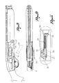
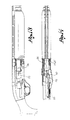
- the rifle shown comprises, in the known manner, a casing or a pivot 20, a barrel 21 with a cartridge chamber 21', a breechblock unit 22, and a triggering device, of which only the trigger 23 is shown.
- the barrel 21 is connected to the casing 20 with a pin 24, which forms an axis of rotation of the barrel between a closed position and a pivoted, opened position.
- the breechblock carriage 22 is guided longitudinally in the casing 20 and can be moved between a closed and an opened position, i.e., a position advanced towards the barrel and a stopped position, respectively, to which correspond the insertion of a cartridge to be fired in the chamber 21' and the removal from the said chamber of a fired cartridge case.
- a removal means 22' which is intended to hook onto the base of the cartridge case so as to drag this case backwards when the breechblock stops.
- the triggering device in the casing does not need a specific description.
- the rifle is able to be fed with and to fire in succession two cartridges, which are indicated as 25 and 26 in the drawings, and which will be referred to below as the first cartridge 25 and the second cartridge 26, respectively.
- the case of a (first) fired cartridge is indicated as 25'.
- a lateral opening 27 for the feeding of the cartridges 25, 26 to be fired and a central lower opening 28 for the exit of the case 25' of a fired cartridge are provided in the casing 20 of the rifle.
- the first cartridge 25 is inserted manually directly into the gun through the lateral opening 27 when the breechblock unit has stopped, and it is inserted at the bottom into the cartridge chamber 21' by means of the breechblock unit when it has advanced.
- a feeding means 29 On the side of the casing 20, at the level of the lateral opening 27, is provided a feeding means 29, which is intended to receive the second cartridge 26 and to feed it automatically after the firing of the first cartridge 25 and the removal of its case 25'.
- the feeding means 29 is in the form of a rotating spoon, which in its rear part is mounted on a pill 31 rotating with the vertical axis.
- the spoon 30 is turned from the rear forward and can rotate from side to side from a starting position outside the casing, in parallel with same, to an internal feed position in which it is turned diagonally within the casing towards the cartridge chamber through the lateral opening 27.
- the spoon 30 is configured to receive and to hold the second cartridge 26 with the base towards the rear.
- a spring 32 which is mounted on the rotating pin 31 and is prestressed between the spoon and casing, tends to make the spoon rotate from the starting position to the feeding position ( Figure 4).
- the spoon 30 interacts with a stop slide 33 to lock the spoon in its starting position against the action of the spring 32 and to unlock the spoon when this [spoon] must be moved into the feeding position.
- the stop slide 33 is guided in the casing 20 in parallel with the breechblock 22. It is stressed by a hook spring 34, which usually keeps it pressed towards the spoon 30 ( Figure 11).
- the spoon in front, has a catch 35 intended to intercept a lug 36 in the rear of the spoon 30 in the manner of holding said spoon in the starting position, the interaction of the catch with the lug of the spoon being ensured by the hook spring 34.
- the spoon in the rear, has a release lip 37 intended to be intcrcepted by the breechblock unit 22 only when same has stopped.
- the spoon 30 has a cavity 38 ( Figures 3, 4 and 7), in which engages a consent lever 39, which acts as a means of enabling the release of the spoon for its movement from the starting position to the said feeding position only if the second cartridge 26 is present on the spoon ( Figure 7).
- a consent lever 39 which acts as a means of enabling the release of the spoon for its movement from the starting position to the said feeding position only if the second cartridge 26 is present on the spoon ( Figure 7).
- the consent lever 39 disengaging it from the cavity 38 of the spoon so that this spoon may rotate towards the interior of the casing.
- the spoon 30 has a cam-shaped wing 40, which interferes with the breechblock when same advances so as to cause the return of the spoon into the starting position after the second cartridge is fed in, where it shall be hooked onto by the slide.
- Figures 1-4 show the gun with the spoon 30 in its starting position, but without the second cartridge 26.
- Figure 5 shows the phase of insertion of the second cartridge 26 into the feeding means, or on the spoon 30, assuming [that] the first cartridge 25 is already in the cartridge chamber 21' and [that] said breechblock is advanced in the closed position as in Figure 6.
- the cartridge 26 on the spoon releases the consent lever 39 as in Figure 7 in order to enable the rotation of the spoon from the starting position.
- the breechblock 22 stops, and the case 25' is removed with the corresponding removal means 22'.
- the brecchblock advances, intercepts, and pushes the second cartridge 26 into the chamber 21', and while simultaneously interacting with the cam wing 40 ( Figures 13 and 14) brings the spoon out into its starting position.
- the second cartridge 26, pushed into the chamber by the breechblock, may then be fired, while the feeding means remains empty on the side of the casing.
Landscapes
- General Engineering & Computer Science (AREA)
- Engineering & Computer Science (AREA)
- Toys (AREA)
- Mechanical Pencils And Projecting And Retracting Systems Therefor, And Multi-System Writing Instruments (AREA)
- Eye Examination Apparatus (AREA)
- Catching Or Destruction (AREA)
- Soil Working Implements (AREA)
- Sealing Of Jars (AREA)
- Table Equipment (AREA)
- Vending Machines For Individual Products (AREA)
- Mechanical Means For Catching Fish (AREA)
- Aiming, Guidance, Guns With A Light Source, Armor, Camouflage, And Targets (AREA)
- Telescopes (AREA)
- Refuge Islands, Traffic Blockers, Or Guard Fence (AREA)
Abstract
Description
Claims (7)
- Semiautomatic sports rifle and shotgun having a smooth or rifled bore, comprising a said casing or pivot (20), a said barrel (21), which is connected to the said casing and has a said cartridge chamber (21'), a said brcechblock unit (22), which can be moved in the said casing between an advanced position and a stopped position, i.e., positions of closing and of opening of the said cartridge chamber, respectively, a said triggering device for controlling the firing, and in which the said rifle can be loaded with a said first cartridge (25), which can be inserted manually into the said cartridge chamber (21'), and a said second cartridge (26), which can be automatically fed in after the firing of the said first cartridge, characterized in that the said casing (20) has a said lateral opening (27) for introducing the cartridges on one side of the said casing and a said lower opening (28) for ejecting from below the said case (25') of each cartridge fired, and in that, at the level of said lateral opening (27) of the said casing is mounted a said rotating lateral feeding means (29), which is able to receive and to hold the said second cartridge (26) during the firing of the said first cartridge (25) and to introduce the said second cartridge into the gun automatically with the aid of the said breechblock unit (22) after the firing of the said first cartridge (25) and the ejection of its empty case through the said lower opening and following the backwards movement of the said breechblock.
- Semiautomatic rifle in accordance with claim 1, in which said lateral feeding means (29) comprises a said spoon (30), which is mounted on a said pin (31) that rotates with the vertical axis, which [spoon] is directed towards the rear from the said rotating pin, is shaped to receive the said cartridge with its base turned towards the rear and can be moved between a starting position outside the said casing, in which it receives and holds said second cartridge (26), and an internal feeding position, in which it is turned diagonally within the said casing, towards the said cartridge chamber (21'), through said lateral opening (27) and with the base of the said cartridge in the position of being intercepted by the said breech block unit (22) when it moves into the advanced position to introduce the said second cartridge into the said chamber (21') of the said barrel.
- Semiautomatic rifle in accordance with claim 2, in which the said spoon (30) is stressed by a said prestressed spring (32), which tends to make the said spoon rotate from the outside starting position to the internal feeding position and in which arc provided a said stop means (33, 35) for defining and holding the said spoon in said starting position against the action of the said spring (32), a said means (39) for enabling the movement of the said spring towards the said feeding position only with the presence of the said second cartridge on the said feeding means, and a said release means (37), which interacts with the said breechblock unit, which stops to disconnect the said stop means that hold the said spoon in the starting position, so that this [spoon] moves in the feeding position.
- Semiautomatic rifle in accordance with claim 3, in which the said stop means (33, 35) and the said release means (37) are integrated into a said slide, arranged on the side of the said casing, in parallel with the said breechblock unit and turned towards the said spoon from the rear forwards.
- Semiautomatic rifle in accordance with claim 3, in which the said means for enabling the movement of the said spoon only in the presence of the second cartridge is a said consent lever (39), which usually engages in a said cavity (38) of the said spoon in order to hold same in the starting position and which is disengaged from the said cavity if the feeding means is loaded with the said cartridge.
- Automatic rifle in accordance with the claims 3-6, in which the said spoon has a said cam-shaped wing (40), which is intended to interact with the said breechblock unit advancing for a return of the said spoon from the feeding position to the starting position, in which it is automatically engaged by the said stop means (33).
- Automatic rifle in accordance with the above claims, in which a said ejection shoulder (41), which intercepts the cartridge case dragged by the said stopping breechblock unit in order to force it to exit from the lower opening, is provided in the said casing (20).
Applications Claiming Priority (2)
| Application Number | Priority Date | Filing Date | Title |
|---|---|---|---|
| IT97BS000064A IT1294536B1 (en) | 1997-07-08 | 1997-07-08 | SEMIAUTOMATIC RIFLE WITH SIDE FEEDING MECHANISM AND BOTTOM EJECTION |
| ITBS970064 | 1997-07-08 |
Publications (3)
| Publication Number | Publication Date |
|---|---|
| EP0890813A2 true EP0890813A2 (en) | 1999-01-13 |
| EP0890813A3 EP0890813A3 (en) | 2000-02-09 |
| EP0890813B1 EP0890813B1 (en) | 2004-05-19 |
Family
ID=11345984
Family Applications (1)
| Application Number | Title | Priority Date | Filing Date |
|---|---|---|---|
| EP98830376A Expired - Lifetime EP0890813B1 (en) | 1997-07-08 | 1998-06-19 | Semiautomatic rifle with lateral feeding mechanism and ejection from below |
Country Status (9)
| Country | Link |
|---|---|
| US (1) | US6044580A (en) |
| EP (1) | EP0890813B1 (en) |
| JP (1) | JP4055179B2 (en) |
| AT (1) | ATE267376T1 (en) |
| DE (1) | DE69823926T2 (en) |
| ES (1) | ES2221143T3 (en) |
| IT (1) | IT1294536B1 (en) |
| PT (1) | PT890813E (en) |
| TR (1) | TR199801314A3 (en) |
Families Citing this family (9)
| Publication number | Priority date | Publication date | Assignee | Title |
|---|---|---|---|---|
| US6347569B1 (en) * | 2000-07-24 | 2002-02-19 | Lawrence V Butler | Semi-automatic gas-operated shotgun |
| US6612062B1 (en) | 2001-02-20 | 2003-09-02 | R.A. Brands, L.L.C. | Carrier locking device |
| BE1016610A3 (en) * | 2005-05-31 | 2007-02-06 | Fn Herstal Sa | Grenade launcher improved. |
| US9958222B2 (en) | 2012-08-01 | 2018-05-01 | Michael H. Blank | Breech bolt for firearm |
| US9417019B2 (en) | 2012-08-24 | 2016-08-16 | Ra Brands, L.L.C. | Fire control for auto-loading shotgun |
| WO2014120317A2 (en) | 2012-11-15 | 2014-08-07 | Slide Fire Solutions, Lp | Belted ammunition feeding device |
| US9400149B2 (en) | 2013-10-04 | 2016-07-26 | Sturm, Ruger & Company, Inc. | Top loading shotgun |
| US9863729B2 (en) | 2014-03-12 | 2018-01-09 | Sharps Rifle Company, Inc. | Breech bolt having asymmetric lugs |
| US10309736B2 (en) * | 2014-05-02 | 2019-06-04 | Sturm, Ruger & Company, Inc. | Shell loading system for firearm |
Family Cites Families (16)
| Publication number | Priority date | Publication date | Assignee | Title |
|---|---|---|---|---|
| BE401166A (en) * | ||||
| US273131A (en) * | 1883-02-27 | nemetz | ||
| DE53064C (en) * | CH. E. sneider in Baltimore, Maryland, V. St. A | Multi-loading rifle with a detachable magazine tube attached next to the barrel | ||
| FR456184A (en) * | 1913-03-31 | 1913-08-19 | Automatic Fire Arms Company | Single shot firing device, for repeating firearms |
| US1905922A (en) * | 1930-05-10 | 1933-04-25 | Remington Arms Co Inc | Firearm |
| US2024125A (en) * | 1934-09-06 | 1935-12-10 | Bochnak Andrew | Machine gun |
| BE488344A (en) * | 1948-04-13 | |||
| US2586509A (en) * | 1950-03-22 | 1952-02-19 | Val A Browning | Carrier latch for repeating firearms |
| US2945423A (en) * | 1957-06-25 | 1960-07-19 | Harold D Allyn | Firearm |
| US2871606A (en) * | 1957-08-02 | 1959-02-03 | Olin Mathieson | Sear safety operated by loading cover and breech bolt |
| US3035495A (en) * | 1958-07-03 | 1962-05-22 | Fairchild Engine & Airplane | Cartridge feeding mechanism |
| US3058399A (en) * | 1959-12-14 | 1962-10-16 | Harold D Allyn | Receiver with t-slot opening for a slide block |
| US3540345A (en) * | 1968-06-05 | 1970-11-17 | Baron C Wolfe | Ammunition feed for a machine gun |
| US3631621A (en) * | 1969-05-15 | 1972-01-04 | Luigi Tito | Lifter mechanism for an automatic shotgun |
| US3919800A (en) * | 1974-03-01 | 1975-11-18 | Browning Arms Co | Facile loading repeating firearm |
| US3996685A (en) * | 1975-11-14 | 1976-12-14 | Remington Arms Company, Inc. | Shell cut-off latch |
-
1997
- 1997-07-08 IT IT97BS000064A patent/IT1294536B1/en active IP Right Grant
-
1998
- 1998-06-15 US US09/094,709 patent/US6044580A/en not_active Expired - Lifetime
- 1998-06-19 PT PT98830376T patent/PT890813E/en unknown
- 1998-06-19 AT AT98830376T patent/ATE267376T1/en not_active IP Right Cessation
- 1998-06-19 ES ES98830376T patent/ES2221143T3/en not_active Expired - Lifetime
- 1998-06-19 DE DE69823926T patent/DE69823926T2/en not_active Expired - Fee Related
- 1998-06-19 EP EP98830376A patent/EP0890813B1/en not_active Expired - Lifetime
- 1998-07-03 JP JP18871998A patent/JP4055179B2/en not_active Expired - Fee Related
- 1998-07-08 TR TR1998/01314A patent/TR199801314A3/en unknown
Non-Patent Citations (1)
| Title |
|---|
| None |
Also Published As
| Publication number | Publication date |
|---|---|
| ITBS970064A0 (en) | 1997-07-08 |
| ATE267376T1 (en) | 2004-06-15 |
| DE69823926T2 (en) | 2005-06-02 |
| EP0890813A3 (en) | 2000-02-09 |
| DE69823926D1 (en) | 2004-06-24 |
| JP4055179B2 (en) | 2008-03-05 |
| TR199801314A2 (en) | 1999-01-18 |
| IT1294536B1 (en) | 1999-04-12 |
| EP0890813B1 (en) | 2004-05-19 |
| ES2221143T3 (en) | 2004-12-16 |
| US6044580A (en) | 2000-04-04 |
| TR199801314A3 (en) | 1999-01-18 |
| JPH1194497A (en) | 1999-04-09 |
| PT890813E (en) | 2004-09-30 |
| ITBS970064A1 (en) | 1999-01-08 |
Similar Documents
| Publication | Publication Date | Title |
|---|---|---|
| US8015742B2 (en) | Firearm with an ergonomic reloading control group | |
| US5235769A (en) | Pump firearm having a forwardly moving barrel | |
| US10088257B2 (en) | Auto-loading shotgun | |
| US5678340A (en) | Cartridge extractor | |
| EP0890813B1 (en) | Semiautomatic rifle with lateral feeding mechanism and ejection from below | |
| IL46845A (en) | Shoulder arm especially a rifle with a swivel breech member | |
| US6397505B1 (en) | Cartridge casing ejector for a firearm | |
| US4601122A (en) | Device for the timely feeding of cartridges in semi-automatic rifles | |
| EP1003007B1 (en) | Firing mechanism for firearms | |
| IL116330A (en) | Ejection device for fire arm | |
| US6389725B1 (en) | Fire arm with forward ejection or ejection brought to the fore-part of the fire arm | |
| US6389947B1 (en) | Cartridge feed device for a repeating firearm | |
| US3030722A (en) | Receiver with lid covering the ejection slot | |
| EP3931519B1 (en) | Pistol with lock for charger | |
| JPS63251796A (en) | Cartridge case feeder | |
| US3064382A (en) | Gun with ejection through hand grip | |
| US2961791A (en) | Lever operated rifle | |
| EP1345000A1 (en) | Mechanism for loading and feeding a semi-automatic rifle and its operating method | |
| NO151340B (en) | PATTERN EJECTOR DEVICE FOR GEAR | |
| CA1161289A (en) | Stripper for firearm | |
| US539037A (en) | Magazine fieeaem | |
| US1088950A (en) | Safety device for repeating firearms. | |
| EP0434160A1 (en) | Method for the timely opening of a cartridge magazine in a shotgun and the device for implementing said method | |
| JPH0534600B2 (en) | ||
| WO1982003452A1 (en) | Ejector system for a gun of the break-open type |
Legal Events
| Date | Code | Title | Description |
|---|---|---|---|
| PUAI | Public reference made under article 153(3) epc to a published international application that has entered the european phase |
Free format text: ORIGINAL CODE: 0009012 |
|
| AK | Designated contracting states |
Kind code of ref document: A2 Designated state(s): AT BE CH DE ES FI FR GB GR IT LI PT SE |
|
| AX | Request for extension of the european patent |
Free format text: AL;LT;LV;MK;RO;SI |
|
| PUAL | Search report despatched |
Free format text: ORIGINAL CODE: 0009013 |
|
| AK | Designated contracting states |
Kind code of ref document: A3 Designated state(s): AT BE CH CY DE DK ES FI FR GB GR IE IT LI LU MC NL PT SE |
|
| AX | Request for extension of the european patent |
Free format text: AL;LT;LV;MK;RO;SI |
|
| RIC1 | Information provided on ipc code assigned before grant |
Free format text: 7F 41A 9/12 A, 7F 41A 9/55 B |
|
| 17P | Request for examination filed |
Effective date: 20000713 |
|
| AKX | Designation fees paid |
Free format text: AT BE CH DE ES FI FR GB GR IT LI PT SE |
|
| 17Q | First examination report despatched |
Effective date: 20021121 |
|
| GRAP | Despatch of communication of intention to grant a patent |
Free format text: ORIGINAL CODE: EPIDOSNIGR1 |
|
| GRAS | Grant fee paid |
Free format text: ORIGINAL CODE: EPIDOSNIGR3 |
|
| GRAA | (expected) grant |
Free format text: ORIGINAL CODE: 0009210 |
|
| AK | Designated contracting states |
Kind code of ref document: B1 Designated state(s): AT BE CH DE ES FI FR GB GR IT LI PT SE |
|
| PG25 | Lapsed in a contracting state [announced via postgrant information from national office to epo] |
Ref country code: LI Free format text: LAPSE BECAUSE OF FAILURE TO SUBMIT A TRANSLATION OF THE DESCRIPTION OR TO PAY THE FEE WITHIN THE PRESCRIBED TIME-LIMIT Effective date: 20040519 Ref country code: FI Free format text: LAPSE BECAUSE OF FAILURE TO SUBMIT A TRANSLATION OF THE DESCRIPTION OR TO PAY THE FEE WITHIN THE PRESCRIBED TIME-LIMIT Effective date: 20040519 Ref country code: CH Free format text: LAPSE BECAUSE OF FAILURE TO SUBMIT A TRANSLATION OF THE DESCRIPTION OR TO PAY THE FEE WITHIN THE PRESCRIBED TIME-LIMIT Effective date: 20040519 Ref country code: AT Free format text: LAPSE BECAUSE OF FAILURE TO SUBMIT A TRANSLATION OF THE DESCRIPTION OR TO PAY THE FEE WITHIN THE PRESCRIBED TIME-LIMIT Effective date: 20040519 |
|
| REG | Reference to a national code |
Ref country code: GB Ref legal event code: FG4D |
|
| REG | Reference to a national code |
Ref country code: CH Ref legal event code: EP |
|
| REF | Corresponds to: |
Ref document number: 69823926 Country of ref document: DE Date of ref document: 20040624 Kind code of ref document: P |
|
| PG25 | Lapsed in a contracting state [announced via postgrant information from national office to epo] |
Ref country code: SE Free format text: LAPSE BECAUSE OF FAILURE TO SUBMIT A TRANSLATION OF THE DESCRIPTION OR TO PAY THE FEE WITHIN THE PRESCRIBED TIME-LIMIT Effective date: 20040819 Ref country code: GR Free format text: LAPSE BECAUSE OF FAILURE TO SUBMIT A TRANSLATION OF THE DESCRIPTION OR TO PAY THE FEE WITHIN THE PRESCRIBED TIME-LIMIT Effective date: 20040819 |
|
| REG | Reference to a national code |
Ref country code: PT Ref legal event code: SC4A Free format text: AVAILABILITY OF NATIONAL TRANSLATION Effective date: 20040805 |
|
| REG | Reference to a national code |
Ref country code: CH Ref legal event code: PL |
|
| REG | Reference to a national code |
Ref country code: ES Ref legal event code: FG2A Ref document number: 2221143 Country of ref document: ES Kind code of ref document: T3 |
|
| ET | Fr: translation filed | ||
| PLBE | No opposition filed within time limit |
Free format text: ORIGINAL CODE: 0009261 |
|
| STAA | Information on the status of an ep patent application or granted ep patent |
Free format text: STATUS: NO OPPOSITION FILED WITHIN TIME LIMIT |
|
| 26N | No opposition filed |
Effective date: 20050222 |
|
| PGFP | Annual fee paid to national office [announced via postgrant information from national office to epo] |
Ref country code: ES Payment date: 20080508 Year of fee payment: 11 |
|
| PGFP | Annual fee paid to national office [announced via postgrant information from national office to epo] |
Ref country code: DE Payment date: 20080523 Year of fee payment: 11 |
|
| PGFP | Annual fee paid to national office [announced via postgrant information from national office to epo] |
Ref country code: FR Payment date: 20080630 Year of fee payment: 11 |
|
| PGFP | Annual fee paid to national office [announced via postgrant information from national office to epo] |
Ref country code: GB Payment date: 20080521 Year of fee payment: 11 |
|
| GBPC | Gb: european patent ceased through non-payment of renewal fee |
Effective date: 20090619 |
|
| REG | Reference to a national code |
Ref country code: FR Ref legal event code: ST Effective date: 20100226 |
|
| PG25 | Lapsed in a contracting state [announced via postgrant information from national office to epo] |
Ref country code: FR Free format text: LAPSE BECAUSE OF NON-PAYMENT OF DUE FEES Effective date: 20090630 |
|
| PG25 | Lapsed in a contracting state [announced via postgrant information from national office to epo] |
Ref country code: GB Free format text: LAPSE BECAUSE OF NON-PAYMENT OF DUE FEES Effective date: 20090619 |
|
| PG25 | Lapsed in a contracting state [announced via postgrant information from national office to epo] |
Ref country code: DE Free format text: LAPSE BECAUSE OF NON-PAYMENT OF DUE FEES Effective date: 20100101 |
|
| PGFP | Annual fee paid to national office [announced via postgrant information from national office to epo] |
Ref country code: PT Payment date: 20100616 Year of fee payment: 13 |
|
| REG | Reference to a national code |
Ref country code: ES Ref legal event code: FD2A Effective date: 20090620 |
|
| PG25 | Lapsed in a contracting state [announced via postgrant information from national office to epo] |
Ref country code: ES Free format text: LAPSE BECAUSE OF NON-PAYMENT OF DUE FEES Effective date: 20090620 |
|
| PGFP | Annual fee paid to national office [announced via postgrant information from national office to epo] |
Ref country code: BE Payment date: 20110614 Year of fee payment: 14 Ref country code: IT Payment date: 20110615 Year of fee payment: 14 |
|
| REG | Reference to a national code |
Ref country code: PT Ref legal event code: MM4A Free format text: LAPSE DUE TO NON-PAYMENT OF FEES Effective date: 20111219 |
|
| PG25 | Lapsed in a contracting state [announced via postgrant information from national office to epo] |
Ref country code: PT Free format text: LAPSE BECAUSE OF NON-PAYMENT OF DUE FEES Effective date: 20111219 |
|
| BERE | Be: lapsed |
Owner name: FABBRICA D'ARMI P. *BERETTA S.P.A. Effective date: 20120630 |
|
| PG25 | Lapsed in a contracting state [announced via postgrant information from national office to epo] |
Ref country code: IT Free format text: LAPSE BECAUSE OF NON-PAYMENT OF DUE FEES Effective date: 20120619 |
|
| PG25 | Lapsed in a contracting state [announced via postgrant information from national office to epo] |
Ref country code: BE Free format text: LAPSE BECAUSE OF NON-PAYMENT OF DUE FEES Effective date: 20120630 |