EP0890788A1 - Cremation process and device for a lifeless human body - Google Patents
Cremation process and device for a lifeless human body Download PDFInfo
- Publication number
- EP0890788A1 EP0890788A1 EP97111721A EP97111721A EP0890788A1 EP 0890788 A1 EP0890788 A1 EP 0890788A1 EP 97111721 A EP97111721 A EP 97111721A EP 97111721 A EP97111721 A EP 97111721A EP 0890788 A1 EP0890788 A1 EP 0890788A1
- Authority
- EP
- European Patent Office
- Prior art keywords
- muffle
- openings
- exhaust gas
- annealing
- air
- Prior art date
- Legal status (The legal status is an assumption and is not a legal conclusion. Google has not performed a legal analysis and makes no representation as to the accuracy of the status listed.)
- Withdrawn
Links
Images


Classifications
-
- F—MECHANICAL ENGINEERING; LIGHTING; HEATING; WEAPONS; BLASTING
- F23—COMBUSTION APPARATUS; COMBUSTION PROCESSES
- F23J—REMOVAL OR TREATMENT OF COMBUSTION PRODUCTS OR COMBUSTION RESIDUES; FLUES
- F23J15/00—Arrangements of devices for treating smoke or fumes
- F23J15/02—Arrangements of devices for treating smoke or fumes of purifiers, e.g. for removing noxious material
-
- F—MECHANICAL ENGINEERING; LIGHTING; HEATING; WEAPONS; BLASTING
- F23—COMBUSTION APPARATUS; COMBUSTION PROCESSES
- F23G—CREMATION FURNACES; CONSUMING WASTE PRODUCTS BY COMBUSTION
- F23G1/00—Furnaces for cremation of human or animal carcasses
-
- F—MECHANICAL ENGINEERING; LIGHTING; HEATING; WEAPONS; BLASTING
- F23—COMBUSTION APPARATUS; COMBUSTION PROCESSES
- F23G—CREMATION FURNACES; CONSUMING WASTE PRODUCTS BY COMBUSTION
- F23G5/00—Incineration of waste; Incinerator constructions; Details, accessories or control therefor
- F23G5/08—Incineration of waste; Incinerator constructions; Details, accessories or control therefor having supplementary heating
- F23G5/12—Incineration of waste; Incinerator constructions; Details, accessories or control therefor having supplementary heating using gaseous or liquid fuel
-
- F—MECHANICAL ENGINEERING; LIGHTING; HEATING; WEAPONS; BLASTING
- F23—COMBUSTION APPARATUS; COMBUSTION PROCESSES
- F23G—CREMATION FURNACES; CONSUMING WASTE PRODUCTS BY COMBUSTION
- F23G5/00—Incineration of waste; Incinerator constructions; Details, accessories or control therefor
- F23G5/08—Incineration of waste; Incinerator constructions; Details, accessories or control therefor having supplementary heating
- F23G5/14—Incineration of waste; Incinerator constructions; Details, accessories or control therefor having supplementary heating including secondary combustion
- F23G5/16—Incineration of waste; Incinerator constructions; Details, accessories or control therefor having supplementary heating including secondary combustion in a separate combustion chamber
-
- F—MECHANICAL ENGINEERING; LIGHTING; HEATING; WEAPONS; BLASTING
- F23—COMBUSTION APPARATUS; COMBUSTION PROCESSES
- F23G—CREMATION FURNACES; CONSUMING WASTE PRODUCTS BY COMBUSTION
- F23G5/00—Incineration of waste; Incinerator constructions; Details, accessories or control therefor
- F23G5/50—Control or safety arrangements
-
- F—MECHANICAL ENGINEERING; LIGHTING; HEATING; WEAPONS; BLASTING
- F23—COMBUSTION APPARATUS; COMBUSTION PROCESSES
- F23L—SUPPLYING AIR OR NON-COMBUSTIBLE LIQUIDS OR GASES TO COMBUSTION APPARATUS IN GENERAL ; VALVES OR DAMPERS SPECIALLY ADAPTED FOR CONTROLLING AIR SUPPLY OR DRAUGHT IN COMBUSTION APPARATUS; INDUCING DRAUGHT IN COMBUSTION APPARATUS; TOPS FOR CHIMNEYS OR VENTILATING SHAFTS; TERMINALS FOR FLUES
- F23L15/00—Heating of air supplied for combustion
- F23L15/04—Arrangements of recuperators
-
- F—MECHANICAL ENGINEERING; LIGHTING; HEATING; WEAPONS; BLASTING
- F23—COMBUSTION APPARATUS; COMBUSTION PROCESSES
- F23G—CREMATION FURNACES; CONSUMING WASTE PRODUCTS BY COMBUSTION
- F23G2202/00—Combustion
- F23G2202/10—Combustion in two or more stages
- F23G2202/101—Combustion in two or more stages with controlled oxidant supply
-
- F—MECHANICAL ENGINEERING; LIGHTING; HEATING; WEAPONS; BLASTING
- F23—COMBUSTION APPARATUS; COMBUSTION PROCESSES
- F23G—CREMATION FURNACES; CONSUMING WASTE PRODUCTS BY COMBUSTION
- F23G2205/00—Waste feed arrangements
- F23G2205/18—Waste feed arrangements using airlock systems
-
- F—MECHANICAL ENGINEERING; LIGHTING; HEATING; WEAPONS; BLASTING
- F23—COMBUSTION APPARATUS; COMBUSTION PROCESSES
- F23G—CREMATION FURNACES; CONSUMING WASTE PRODUCTS BY COMBUSTION
- F23G2207/00—Control
- F23G2207/10—Arrangement of sensing devices
- F23G2207/101—Arrangement of sensing devices for temperature
-
- F—MECHANICAL ENGINEERING; LIGHTING; HEATING; WEAPONS; BLASTING
- F23—COMBUSTION APPARATUS; COMBUSTION PROCESSES
- F23G—CREMATION FURNACES; CONSUMING WASTE PRODUCTS BY COMBUSTION
- F23G2207/00—Control
- F23G2207/40—Supplementary heat supply
-
- F—MECHANICAL ENGINEERING; LIGHTING; HEATING; WEAPONS; BLASTING
- F23—COMBUSTION APPARATUS; COMBUSTION PROCESSES
- F23J—REMOVAL OR TREATMENT OF COMBUSTION PRODUCTS OR COMBUSTION RESIDUES; FLUES
- F23J2215/00—Preventing emissions
- F23J2215/30—Halogen; Compounds thereof
- F23J2215/301—Dioxins; Furans
-
- F—MECHANICAL ENGINEERING; LIGHTING; HEATING; WEAPONS; BLASTING
- F23—COMBUSTION APPARATUS; COMBUSTION PROCESSES
- F23J—REMOVAL OR TREATMENT OF COMBUSTION PRODUCTS OR COMBUSTION RESIDUES; FLUES
- F23J2215/00—Preventing emissions
- F23J2215/60—Heavy metals; Compounds thereof
-
- F—MECHANICAL ENGINEERING; LIGHTING; HEATING; WEAPONS; BLASTING
- F23—COMBUSTION APPARATUS; COMBUSTION PROCESSES
- F23J—REMOVAL OR TREATMENT OF COMBUSTION PRODUCTS OR COMBUSTION RESIDUES; FLUES
- F23J2217/00—Intercepting solids
- F23J2217/10—Intercepting solids by filters
- F23J2217/101—Baghouse type
-
- F—MECHANICAL ENGINEERING; LIGHTING; HEATING; WEAPONS; BLASTING
- F23—COMBUSTION APPARATUS; COMBUSTION PROCESSES
- F23J—REMOVAL OR TREATMENT OF COMBUSTION PRODUCTS OR COMBUSTION RESIDUES; FLUES
- F23J2219/00—Treatment devices
- F23J2219/30—Sorption devices using carbon, e.g. coke
-
- F—MECHANICAL ENGINEERING; LIGHTING; HEATING; WEAPONS; BLASTING
- F23—COMBUSTION APPARATUS; COMBUSTION PROCESSES
- F23J—REMOVAL OR TREATMENT OF COMBUSTION PRODUCTS OR COMBUSTION RESIDUES; FLUES
- F23J2219/00—Treatment devices
- F23J2219/80—Quenching
-
- Y—GENERAL TAGGING OF NEW TECHNOLOGICAL DEVELOPMENTS; GENERAL TAGGING OF CROSS-SECTIONAL TECHNOLOGIES SPANNING OVER SEVERAL SECTIONS OF THE IPC; TECHNICAL SUBJECTS COVERED BY FORMER USPC CROSS-REFERENCE ART COLLECTIONS [XRACs] AND DIGESTS
- Y02—TECHNOLOGIES OR APPLICATIONS FOR MITIGATION OR ADAPTATION AGAINST CLIMATE CHANGE
- Y02E—REDUCTION OF GREENHOUSE GAS [GHG] EMISSIONS, RELATED TO ENERGY GENERATION, TRANSMISSION OR DISTRIBUTION
- Y02E20/00—Combustion technologies with mitigation potential
- Y02E20/34—Indirect CO2mitigation, i.e. by acting on non CO2directly related matters of the process, e.g. pre-heating or heat recovery
Definitions
- the invention relates to a method and a device for cremation lifeless, human body, which is in a coffin.
- Cremation is a very old method of burial technical cremation ", however, only began in the 18th century. It underwent a gradual further development in the 19th century. The principles for cremation were set up in a first European congress in Dresden as early as 1876. In particular, the demands for complete combustion were met , the avoidance of odors, the purity of the ashes and an economical operation.
- the first cremation ovens were flame ovens with their own Gas generator running. This was done in a separate gasification room Gas generated from coal mixed with combustion air and burned. The hot exhaust gases were then used to carry out the cremation. Were later Hot air ovens are used, in which the cremation was carried out by hot air, the was generated by heat exchange with hot exhaust gases.
- the elaborate Gas production has been increasing with the development of stoves through gas burners replaced, resulting in a significant simplification of the furnace design led. Then played the design of the combustion chamber to carry out the Cremation the essential role.
- essentially the Deck oven which is still used in a variety of cremation plants is used.
- the VDI Guideline 3891 Emission reduction cremation plants contains numerous hints and recommendations for measures to reduce emissions.
- the exhaust gas emissions resulting from the cremation are currently binding by the 27th Ordinance for Implementation of the Federal Immission Control Act, Ordinance on Cremation Plants, 27th Blmsch V of March 19, 1997 "regulates limit values for afterburning temperature, carbon monoxide, organic substances, total dust as well as dioxins and furans.
- the invention has for its object to incinerate lifeless, human Body a method and a device with a high burnout of the Exhaust gases and the ash to be fed to the urn and thereby create one lower energy requirements, a shorter cremation time and an operational process without any manual intervention.
- the coffin with the one it contains Body is transferred from an encapsulated sluice into a heated by two burners, Temperature-controlled muffle inserted and low-impact on rotating castors put on, being preheated below and above these rolls
- Combustion air is supplied, which sequentially burns the paint on the coffin, the burning of the wood material and the burning of the body run at given air numbers and generate a hot exhaust gas, which together with the exhaust gas from an annealing chamber in the opposite Direction of the ash removal and the falling from the rolls, almost fully oxidized parts flow upward, then into a post-combustion chamber arrives there with the help of a pointing in the direction of flow
- Burner flame is freed from oxidizable organic substances, and after sufficient dwell time heat in a recuperator to the combustion air that enters the muffle after heating, the walls of which are dimensioned that the heat released during the lacquer and wood combustion partially save and release them again during the body burn.
- the process described enables the ashes to burn out completely, requires a short cremation time (55 minutes for a body mass of 75 kg) and low energy consumption (natural gas consumption less than 26 m 3 / n and electrical energy consumption less than 22 kWh per cremation for 75 kg body mass) and releases an exhaust gas with pollutant concentrations that are below the limit values according to the ordinance on cremation systems - 27th Blmsch V. Manual intervention to remove the ashes and to remove blocking parts is not required, which means that the entire process can be fully automated.
- a device is used to carry out the method according to the invention according to claim 10.
- This device has a compact arrangement and the advantage that process-related heat transfer and flow problems be solved in a suitable manner.
- the muffle consists of one pyramid-shaped lower part and a square-shaped upper part, in the Connection level three rotatable rollers perpendicular to the axis of entry of the coffin Inclusion of the coffin are provided, being below and above the Rolling openings for the supply of combustion air are located during two Burners attached above the coffin, the heating and the Take over temperature control of the muffle.
- a device according to DE 196 37 509 can be used.
- the square part of the muffle also closes off one cuboid and a pyramid-shaped part Afterburning chamber with one level with the muffle arranged ceiling and a common vertical wall, which two Passages for guiding the exhaust gas from the muffle contains and with a another, vertical wall connected to the ceiling a vertical Exhaust duct forms, in which a burner for post-combustion of the organic Pollutants are built into the exhaust gas, and from that the vertically downward flowing exhaust gas after deflection through the pyramid-shaped part of the afterburning chamber through vertical upward flow into another vertical channel, above which a recuperator for exhaust gas cooling and combustion air preheating is arranged, through which on the air side a fan-supplied combustion air to the muffle and Post-combustion chamber flows.
- the lower boundary surface of the pyramid-shaped part of the muffle is through a first, upper rotary flap for receiving the during the cremation of parts that fall off the rollers and are almost completely oxidized, after the oxidation time has elapsed, by rotating the first, upper one Conveyor flap is conveyed into an annealing chamber arranged below this which is heated with a designated annealing burner and in turn closes below with a second, lower rotary flap for the purpose of ash removal, two for the extraction of the exhaust gas produced during the annealing Channels are provided which the annealing chamber with the muffle approximately at the level of Connect role level.
- the coffin SA with the body contained therein is open Muff slide valve MS from a lock LS, which is sealed to the atmosphere, through a Transport device transported into the muffle M and there on the horizontal arranged rotatable rollers R1, R2 and R3 placed. Then the in the Lock integrated transport device retracted and the muffle slide MS closed. After a few seconds the coffin begins to burn.
- the combustion air is fed into the muffle M according to FIGS. 1 and 2 below the rollers through openings D7 to D12 and above the rollers through the openings D1 to D6.
- the sub-processes run sequentially in the muffle, Burning paint on the coffin, burning the coffin material, evaporation of the Water content in the body and combustion of the organic mass of the body from. Different air ratios are observed.
- the air ratio is defined than the ratio of the actual air mass flow to the stoichiometric Air mass flow. With a body weight of 75 kg Burning the paint and the coffin material an air ratio of 1.6 to 1.8 adhered to, while the air number when burning the body 2.2 to 2.5 is. Tests have shown that these values are favorable.
- the exhaust gas m ⁇ A1 produced during the combustion flows upwards and passes through two passages DT1 and DT2 (FIGS. 3, 4 and 5) into the connected post-combustion chamber N (FIGS. 1 and 2).
- the exhaust gas temperature at the exit of the Muffle M (immediately before DT1 and DT2) is always higher than 700 ° C.
- the exhaust gas temperature can drop below 650 ° C.
- two controlled muffle burners B0 and B1 are arranged in the muffle M, which are automatically switched on as soon as the exhaust gas temperature at the outlet of the muffle falls below 650 ° C. These burners then regulate the exhaust gas temperature by changing the fuel supply until their output has dropped to 20% of the full output of 230 kW each, which results in a shutdown.
- the parts of the coffin and body oxidized by combustion fall off the roles in the pyramid-shaped part MP of the muffle M and are from a first, upper rotary valve DK1 caught (Fig. 3 and 4). After about 45 to 55 min. the combustion process in the muffle M is finished. On the reels R1 up to R3, parts that are still left are turned by turning these rollers in both Directions brought down and on the first, top rotary flap DK1 collected. Parts already there from the same cremation cycle become with a further oxidation through the openings D9 and D12 (Fig. 2) preheated air. After completing the combustion process in the Muffle, the muffle burner B0 and B1 are switched off, provided that this is done beforehand were still in operation.
- the burned parts are turned by turning the first, upper rotary valve DK1 in an annealing chamber AK (Fig. 2 and 4) promoted.
- the first, upper rotary valve DK1 then rotates into its starting position back, and the loading of the Muffle M with the next coffin can begin.
- the annealing chamber AK In the annealing chamber AK the annealing of the remaining solid parts from the cremation to the residual oxidation of the not yet completely burned organic components. Of the bottom of the annealing chamber AK is closed by a second, lower rotary valve DK2 formed (Fig. 3 and 4), which still has an exit when annealing prevents oxidizing, solid parts and forms the seal to the atmosphere.
- the heat for annealing is provided by an annealing burner B3 with a Power of 90 kW (Fig. 3 and 4). Annealing takes about 20 to 25 minutes. After During this time, the burnout burner B3 is switched off and the second, lower one Rotary flap DK2 turned so that the fully oxidized parts (ash) in one Ash container can be filled.
- Rotary flap DK2 returns to its initial position and burner B3 is set to 20% switched on its performance.
- the exhaust gas generated during the annealing passes through two in the muffle wall WP1 of the pyramidal part MP Muffle M provided channels C3 and C4 (Fig. 2) in the area between the Muffle slide MS and the newly introduced coffin and thereby forms one additional heat source.
- the exhaust gases generated during cremation (combustion in the muffle M and in the annealing chamber AK) still contain unburned, organic substances and carbon monoxide.
- they After leaving the muffle M, they are treated through the intended passages DT1 and DT2 in a connected post-combustion chamber N (FIGS. 1, 3 and 4).
- the resulting exhaust gas m ⁇ A1 flows down through a vertical channel C1 and is brought to temperatures of 850 to 900 ° C by means of an afterburner B2 (power 230 kW), the flame of which points into the downward flow, provided this order of magnitude Temperature was not reached before.
- the resulting exhaust gas m ⁇ A2 is deflected in the pyramid-shaped part NP of the afterburning chamber N and flows through a further channel C2 upwards to a downstream recuperator RE (FIGS. 3, 4 and 5).
- the exhaust gas m ⁇ A2 gives off heat to the incoming combustion air m ⁇ L1 , which is conveyed by fan V1 via line L1 into the air side of recuperator RE.
- the exhaust gas m ⁇ A2 reaches a dwell time of more than 0.5 s in the post-combustion chamber N in the presence of high turbulence, which ensures sufficient burnout.
- the exhaust gas m ⁇ A2 cools down to temperatures of 600 to 650 ° C and is drawn off through line L8.
- the combustion air m ⁇ L1 is heated to outlet temperatures of 350 to 450 ° C. It is after the recuperator RE through line L3 via three branches L4, L5 and L6 (Fig. 1), which contain adjustable diaphragms K2, K3 and K7, the cuboid part MQ (openings D1 to D6), the pyramid part MP ( Openings D7 to D12) of the muffle M and channel C1 of the afterburning chamber (openings D23 and D24).
- the mass flow of the supplied combustion air m ⁇ L1 depends on the oxygen content at the outlet of the afterburning chamber N, which is 10 to 12 volume percent.
- the speed of fan V1 and thus the mass flow m constitution L1 are changed with the oxygen content. If the air after the recuperator RE is too high, part of this air m ⁇ LE is added to the exhaust gas mass flow m ⁇ A2 leaving the recuperator in line L8, as a result of which the temperature decreases due to air flowing in.
- the reference variable for this is the temperature of the air behind the recuperator RE, which opens a regulated flap K5 when 470 ° C is exceeded.
- cooling air is introduced before the recuperator RE through the control flap K4, before the waste heat boiler A through the control flap K6 and before the fabric filter F through the control flap K9 (FIG. 1).
- the burners B0 to B3 are supplied with air m ⁇ LB at constant inlet pressure by the fan V3. Likewise, the amount of gas m ⁇ G required for the burners is supplied at a constant admission pressure.
- Fig. 2 shows the muffle M and the post-combustion chamber N in different Views without the built-in burners B0 to B3.
- 3 and 6 receive a perspective view of the muffle M and the afterburning chamber N.
- the muffle M consists of a pyramid-shaped lower part MP and a cuboid upper part MQ.
- connection level e 3 are three rotatable rollers R1, R2 and R3 for Inclusion of the coffin SA provided (Fig. 3 and 4).
- coffin SA are in the boundary walls of the cuboid MQ on both sides 3 openings D1, D2 and D3 or D4, D5 and D6 for the supply of the preheated combustion air arranged (Fig. 2).
- the combustion air is below the rollers to the pyramid-shaped part through the openings D7, D8 and D9 in the Boundary wall WP3 and through the openings D10 to D12 in the Boundary wall WP4 supplied.
- the muffle M which is shown in FIGS. 3 and 4 of a first, upper rotary valve DK1 and a second, lower rotary valve DK2 is limited.
- the annealing burner B3, which enters an opening D22, is used for annealing is embedded (Fig. 2). After annealing, the annealed parts are Rotation of the second, lower rotary flap DK2 is conveyed into an ash container.
- the muffle is through two passages DT1 and DT2 according to FIGS. 2 and 5 with one Afterburning chamber N connected, which in turn according to FIG. 1 from a cuboid part NQ and a pyramid-shaped part NP.
- the Muffle and the post-combustion chamber have the common vertical Wall W3, which with another vertical wall W4 a vertical Exhaust duct C1 forms for exhaust gas routing (drop train).
- The is used for afterburning Afterburner B2, which is embedded in the ceiling G1 through the opening D18.
- the Wall W4 forms another vertical wall with another wall W5 Exhaust duct C2 (ascent).
- the exhaust gas flows upwards to the recuperator RE, which is integrated in channel C2.
- the exhaust gas generated in the annealing chamber AK flows through two exhaust gas channels C3 and C4, which are in the boundary wall WP1 of the pyramidal part MP of the muffle are to the muffle (Fig. 2).
- the end of these channels includes the roller level e from (Fig.3).
Abstract
Description
Die Erfindung betrifft ein Verfahren und eine Vorrichtung zur Einäscherung leblosen, menschlichen Körpers, welcher sich in einem Sarg befindet.The invention relates to a method and a device for cremation lifeless, human body, which is in a coffin.
Die Einäscherung stellt eine recht alte Methode der Bestattung dar. Die
![]()
![]()
Die ersten Einäscherungsöfen wurden als Flammöfen mit einem eigenen Gasgenerator ausgeführt. Dabei wurde das im einem separaten Vergasungsraum aus Kohle erzeugte Gas mit Verbrennungsluft vermischt und verbrannt. Die heißen Abgase dienten dann zur Durchführung der Einäscherung. Später wurden Heißluftöfen eingesetzt, bei denen die Einäscherung durch heiße Luft erfolgte, die durch Wärmeaustausch mit heißen Abgasen erzeugt wurde. Die aufwendige Gaserzeugung wurde mit fortschreitender Entwicklung der Öfen durch Gasbrenner ersetzt, was zu einer wesentlichen Vereinfachung der Ofenkonstruktion führte. Danach spielte die Gestaltung der Brennkammer zur Durchführung der Einäscherung die wesentliche Rolle. Hier setzte sich im wesentlichen der Etagenofen durch, der heute noch in einer Vielzahl von Einäscherungsanlagen verwendet wird. Kennzeichnend für den Etagenofen ist die Anordnung des feststehenden, feuerfesten Rostes angeordnet in einer Muffel, die darunter befindliche Aschenentnahme und die Abgasführung in Richtung der herabfallenden, verbrannten oder verbrennenden Teile aus der Einäscherung. Neben dem gasbeheizten Etagenofen sind auch vereinzelt elektrisch beheizte Öfen und Flachbettöfen vorzufinden. Letztere bauen zwar sehr kompakt, haben jedoch den Nachteil der aufwendigen und unbequemen Aschenentnahme. Elektrisch beheizte Öfen bauen ebenso kompakt, haben jedoch einen hohen Primärenergiebedarf und verursachen durch hohe Temperaturen Stickoxide.The first cremation ovens were flame ovens with their own Gas generator running. This was done in a separate gasification room Gas generated from coal mixed with combustion air and burned. The hot exhaust gases were then used to carry out the cremation. Were later Hot air ovens are used, in which the cremation was carried out by hot air, the was generated by heat exchange with hot exhaust gases. The elaborate Gas production has been increasing with the development of stoves through gas burners replaced, resulting in a significant simplification of the furnace design led. Then played the design of the combustion chamber to carry out the Cremation the essential role. Here essentially the Deck oven, which is still used in a variety of cremation plants is used. The arrangement of the fixed, refractory grate arranged in a muffle, the one below Ash removal and exhaust gas routing in the direction of the falling, burned or burning parts from cremation. Next to the gas-heated deck ovens are also occasionally electrically heated ovens and Find flat bed ovens. The latter build very compact, but have the Disadvantage of the complex and uncomfortable ash removal. Electrical heated ovens are just as compact, but have a high one Primary energy requirement and cause nitrogen oxides due to high temperatures.
Die verbrennungstechnische und die konstruktive Seite sowie die Automation der
Beschickung und der Aschenentnahme prägten bis Mitte des 20. Jahrhunderts die
Weiterentwicklung von Einäschetungsanlagen, über deren Grundformen im Buch
Neben der Abgasqualität spielen die Qualität und der Umgang mit der nach der Oxidation für die Urne bestimmte, verbleibende Asche eine entscheidende Rolle. Dieser Punkt wird in der Bundesrepublik Deutschland durch entsprechende Gesetzte und Verordnungen der Bundesländer geregelt. Danach sind Einäscherungsanlagen so zu errichten, daß die Asche rein, vollständig und unvermischt gewonnen werden kann. Diese Forderung kann nur durch ein Ausglühen der festen, teilweise noch unverbrannten Bestandteile aus der Hauptverbrennung erfüllt werden. Bei ausgeführten Einäscherungsöfen erfolgt das Ausglühen in einer hierfür vorgesehenen Ausglühkammer, welche durch einen separaten Ausglühbrenner beheizt wird. Gleichzeitig durchströmt das Abgas aus dem Muffelbereich die Ausglühkammer, vermischt sich mit dem dort entstehenden Abgas und gelangt in die nachgeschaltete Abgaskühlung. Diese Abgasführung hat zwei wesentliche Nachteile: einerseits wird das heiße Abgas des Ausglühbrenners ohne feuerungstechnische Nutzung dem Abgas aus der Muffel zugesetzt, andererseits wird ein Mitreißen der noch nicht ausgeglühten Teile aus der Einäscherung begünstigt. Mitgerissene Teile wirken aufgrund ihres Kohlenstoffgehaltes wie Aktivkohle und adsorbieren während des Abkühlens Schadstoffe, unter anderem auch Dioxine und Furane. Die der Anlage zu entnehmende Filterasche kann daher hohe Schadstofffrachten aufweisen,In addition to the exhaust gas quality, the quality and handling of the after play Oxidation destined for the urn, remaining ashes play a crucial role. This point is made in the Federal Republic of Germany by appropriate Laws and regulations of the federal states regulated. After that are To set up cremation plants so that the ashes are pure, complete and can be obtained unmixed. This requirement can only be met by a Annealing of the solid, partly still unburned components from the Main combustion to be met. With cremation ovens carried out the annealing in a designated annealing chamber, which by a separate annealing burner is heated. At the same time, the exhaust gas flows out the annealing chamber in the muffle area mixes with the resulting one Exhaust gas and reaches the downstream exhaust gas cooling. This Exhaust gas routing has two major disadvantages: on the one hand, the hot exhaust gas of the burnout burner without using the exhaust gas from the Muffle added, on the other hand entrainment of those that have not yet been annealed Parts from the cremation favored. Entrained parts work due to their Carbon content such as activated carbon and adsorb during cooling Pollutants, including dioxins and furans. The plant too filter ash can therefore have high pollutant loads,
Ein weiteres Problem ist durch den ungenügenden Transport eingeäscherter Teile bedingt. In Etagenöfen bleiben häufig eingeäscherte, feste Teile im Bereich des feststehenden Rostes ( Sargeinfuhrebene) stecken. Sie erreichen ohne fremde Hilfe nicht die Ausglühkammer. Hier wird durch einen Handeingriff, z.B. durch Stochern mit einer Metallanze, Abhilfe geschaffen. Dazu muß der Ofen geöffnet werden, was abgesehen von einem zusätzlichen Energiebedarf ein Sicherheitsproblem darstellt. Another problem is the insufficient transportation of cremated parts conditionally. Cremated, solid parts often remain in the area of the fixed grate (coffin entry level). You can reach without strangers Don't help the annealing chamber. Here is a manual intervention, e.g. by Poking with a metal lance, remedy. To do this, the oven must be opened be what apart from an additional energy requirement Represents security problem.
Auch der Energiebedarf von Einäscherungsanlagen liegt recht hoch und führt zu entsprechend hohen Betriebskosten. Dies ist in den großen Luftzahlen zwischen 3 und 4 begründet, die in bestehenden Anlagen aus Materialgründen und bedingt durch die Verfahrensführung eingestellt werden. Die Aufheizung und Förderung des Überschußluftanteils erfordert einen hohen thermischen und elektrischen Energiebedarf.The energy requirement of cremation plants is also quite high and leads to correspondingly high operating costs. This is in the large air numbers between 3 and 4 justifies that in existing plants due to material reasons and conditions be discontinued by the conduct of the procedure. Heating and promotion the excess air portion requires a high thermal and electrical Energy requirements.
Der Erfindung liegt die Aufgabe zugrunde, zur Einäscherung leblosen, menschlichen Körpers ein Verfahren und eine Vorrichtung mit einem hohen Ausbrand der Abgase und der der Urne zuzuführenden Asche zu schaffen und dabei einen niedrigeren Energiebedarf, eine kürzere Einäscherungszeit und einen Betriebsablauf ohne jeglichen Handeingriff zu erreichen.The invention has for its object to incinerate lifeless, human Body a method and a device with a high burnout of the Exhaust gases and the ash to be fed to the urn and thereby create one lower energy requirements, a shorter cremation time and an operational process without any manual intervention.
Diese Aufgabe wird erfindungsgemäß nach dem Patentanspruch 1 gelöst.This object is achieved according to
Der wesentliche Gedanke ist der folgende: Der Sarg mit dem darin enthaltenen Körper wird aus einer gekapselten Schleuse in eine durch zwei Brenner aufgeheizte, temperaturgeregelte Muffel eingeführt und auf drehbare Rollen stoßarm aufgesetzt, wobei unterhalb und oberhalb dieser Rollen vorgewärmte Verbrennungsluft zugeführt wird, wodurch sequentiell die Verbrennung des Lackes am Sarg, die Verbrennung des Holzwerkstoffes und die Verbrennung des Körpers bei vorgegebenen Luftzahlen ablaufen und ein heißes Abgas erzeugen, welches gemeinsam mit dem Abgas aus einer Ausglühkammer in entgegengesetzter Richtung der Aschenentnahme und der von den Rollen herabfallenden, nahezu vollständig oxidierten Teile aufwärtsströmt, anschließend in eine Nachverbrennungskammer gelangt, dort mit Hilfe einer in Strömungsrichtung weisende Brennerflamme von oxidierbaren organischen Stoffen befreit wird, und nach ausreichender Verweilzeit Wärme in einem Rekuperator an die Verbrennungsluft abgibt, die nach Erwärmung in die Muffel eintritt, deren Wände so bemessen sind, daß sie die während der Lack- und Holzverbrennung freiwerdende Wärme teilweise speichem und diese während der Körperverbrennung wieder abgeben. The main idea is the following: The coffin with the one it contains Body is transferred from an encapsulated sluice into a heated by two burners, Temperature-controlled muffle inserted and low-impact on rotating castors put on, being preheated below and above these rolls Combustion air is supplied, which sequentially burns the paint on the coffin, the burning of the wood material and the burning of the body run at given air numbers and generate a hot exhaust gas, which together with the exhaust gas from an annealing chamber in the opposite Direction of the ash removal and the falling from the rolls, almost fully oxidized parts flow upward, then into a post-combustion chamber arrives there with the help of a pointing in the direction of flow Burner flame is freed from oxidizable organic substances, and after sufficient dwell time heat in a recuperator to the combustion air that enters the muffle after heating, the walls of which are dimensioned that the heat released during the lacquer and wood combustion partially save and release them again during the body burn.
Bei der Durchführung des Verfahrens ist es vorteilhaft, die in der Muffel nahezu vollständig oxidierten Teile aus der Einäscherung durch Drehung der Rollen um ihre Längsachse nach Ablauf der Oxidationszeit herabfallen zu lassen und mit einer ersten, oberen Drehklappe aufzufangen, welche ihrerseits durch Drehung die aufgefangenen Teile in eine Ausglühkammer befördert, die mit einer zweiten, untereren Drehklappe abschließt und worin das Ausglühen durch eine Brenneflamme durchgeführt wird, deren Abgas über einen Kanal in die Muffel gelangt und zur Aufheizung bzw. Verbrennung des nächsten, bereits eingeführten Sarges beiträgt.When carrying out the process it is advantageous to have almost in the muffle fully oxidized parts from the cremation by rotating the rollers around to let their longitudinal axis fall after the oxidation time and with a first, upper rotary flap to catch, which in turn by rotation the collected parts are conveyed into an annealing chamber, which is lower rotary valve closes and in which the annealing by a Burning flame is carried out, the exhaust gas of which is channeled into the muffle arrives and for heating or burning the next, already introduced Sarges contributes.
Mit besonderem Vorteil lassen sich auch die Verfahrensschritte nach den Ansprüchen 2 bis 9 anwenden.The process steps according to the Apply claims 2 to 9.
Das beschriebene Verfahren ermöglicht einen vollständigen Ausbrand der Asche,
benötigt eine kurze Einäscherungszeit (55 Minuten für eine Körpermasse von 75
kg) bei niedrigen Energieverbräuchen (Erdgasbedarf kleiner als 26 m 3 / n und
elektrischer Energiebedarf kleiner als 22 kWh je Einäscherung für 75 kg
Körpermasse) und entläßt ein Abgas mit Schadstoffkonzentrationen, die unterhalb
der Grenzwerte nach der Verordnung über Anlagen zur Feuerbestattung - 27.
Blmsch V - liegen. Handeingriffe zur Entfernung der Asche und zur Entfernung
blockierender Teile sind nicht erforderlich, wodurch das gesamte Verfahren
vollständig automatisiert werden kann.The process described enables the ashes to burn out completely, requires a short cremation time (55 minutes for a body mass of 75 kg) and low energy consumption (natural gas consumption less than 26
Zur Durchführung des erfindungsgemäßen Verfahrens benutzt man eine Vorrichtung gemäß Anspruch 10. Diese Vorrichtung hat eine kompakte Anordnung und den Vorteil, daß verfahrensbedingte Wärmeübertragungs- und Strömungsprobleme in geeigneter Weise gelöst werden. Die Muffel besteht aus einem pyramidenförmigen Unterteil und einem quarderförmigen Oberteil, in deren Anschlußebene drei drehbare Rollen senkrecht zur Einfuhrachse des Sarges zur Aufnahme des Sarges vorgesehen sind, wobei sich unterhalb und oberhalb der Rollen Öffnungen für die Zufuhr der Verbrennungsluft befinden, während zwei oberhalb des Sarges angebrachte Brenner die Aufheizung und die Temperaturregelung der Muffel übernehmen. Zur Realisierung der Rollen kann vorteilhaft eine Vorrichtung gemäß DE 196 37 509 benutzt werden.A device is used to carry out the method according to the invention according to claim 10. This device has a compact arrangement and the advantage that process-related heat transfer and flow problems be solved in a suitable manner. The muffle consists of one pyramid-shaped lower part and a square-shaped upper part, in the Connection level three rotatable rollers perpendicular to the axis of entry of the coffin Inclusion of the coffin are provided, being below and above the Rolling openings for the supply of combustion air are located during two Burners attached above the coffin, the heating and the Take over temperature control of the muffle. To realize the roles can advantageously a device according to DE 196 37 509 can be used.
An den quarderförmigen Teil der Muffel schließt sich eine ebenso aus einem quaderförmigen und einem pyramidenförmigen Teil zusammengesetzte Nachverbrennungskammer an, mit einer in gleicher Höhe mit der Muffel angeordneten Decke sowie einer gemeinsamen senkrechten Wand, welche zwei Durchtritte zur Führung des Abgases aus der Muffel enthält und mit einer weiteren, senkrechten und mit der Decke verbundenen Wand einen senkrechten Abgaskanal bildet, in den ein Brenner zur Nachverbrennung der organischen Schadstoffe im Abgas eingebaut ist, und aus dem das senkrecht abwärts strömende Abgas nach Umlenkung durch den pyramidenförmigen Teil der Nachverbrennungskammer durch senkrechte Aufwärtsströmung in einen weiteren senkrechten Kanal gelangt, oberhalb dessen ein Rekuperator zur Abgaskühlung und Verbrennungsluftvorwärmung angeordnet ist, durch den luftseitig die von einem Ventilator geförderte Verbrennungsluft zur Muffel und zur Nachverbrennungskammer strömt. Weitere vorteilhafte Merkmale der erfindungsgemäßen Vorrichtung resultieren aus den Ansprüchen 11 bis 24.The square part of the muffle also closes off one cuboid and a pyramid-shaped part Afterburning chamber with one level with the muffle arranged ceiling and a common vertical wall, which two Passages for guiding the exhaust gas from the muffle contains and with a another, vertical wall connected to the ceiling a vertical Exhaust duct forms, in which a burner for post-combustion of the organic Pollutants are built into the exhaust gas, and from that the vertically downward flowing exhaust gas after deflection through the pyramid-shaped part of the afterburning chamber through vertical upward flow into another vertical channel, above which a recuperator for exhaust gas cooling and combustion air preheating is arranged, through which on the air side a fan-supplied combustion air to the muffle and Post-combustion chamber flows. Other advantageous features of The device according to the invention result from claims 11 to 24.
Die untere Begrenzungsfläche des pyramidenförmigen Teils der Muffel wird durch eine erste, obere Drehklappe zur Aufnahme der während der Einäscherung von den Rollen herabfallenden und nahezu vollständig oxidierten Teile begrenzt, wobei diese nach Ablauf der Oxidationszeit durch Drehung der ersten, oberen Drehklappe in eine unterhalb dieser angeordnete Ausglühkammer befördert werden, die mit einem hierfür vorgesehenen Ausglühbrenner beheizt wird und ihrerseits unten mit einer zweiten, unteren Drehklappe zwecks Ascheabzug abschließt, wobei für den Abzug des beim Ausglühen entstehenden Abgases zwei Kanäle vorgesehen sind, die die Ausglühkammer mit der Muffel etwa in Höhe der Rollenebene verbinden. The lower boundary surface of the pyramid-shaped part of the muffle is through a first, upper rotary flap for receiving the during the cremation of parts that fall off the rollers and are almost completely oxidized, after the oxidation time has elapsed, by rotating the first, upper one Conveyor flap is conveyed into an annealing chamber arranged below this which is heated with a designated annealing burner and in turn closes below with a second, lower rotary flap for the purpose of ash removal, two for the extraction of the exhaust gas produced during the annealing Channels are provided which the annealing chamber with the muffle approximately at the level of Connect role level.
Ein Ausführungsbeispiel der Erfindung ist in den nachfolgenden Zeichnungen dargestellt und wird im folgenden näher erläutert. Es zeigen:
- Fig. 1
- : Ablaufschema des erfindungsgemäßen Verfahrens und Funktionsweise der erfindungsgemäßen Vorrichtung
- Fig. 2 bis 6
- : Aufbau der wesentlichen Komponenten der erfindungsgemäßen Vorrichtung
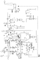
- Fig. 1
- Flow diagram of the method according to the invention and mode of operation of the device according to the invention
- 2 to 6
- : Structure of the essential components of the device according to the invention
Gemäß Figur 1 wird der Sarg SA mit dem darin enthaltenen Körper bei offenem Muffenschieber MS aus einer zur Atmosphäre dichten Schleuse LS durch eine Transportvorrichtung in die Muffel M transportiert und dort auf die horizontal angeordneten drehbaren Rollen R1, R2 und R3 aufgesetzt. Danach wird die in die Schleuse integrierte Transportvorrichtung zurückgefahren und der Muffelschieber MS geschlossen. Nach wenigen Sekunden beginnt dann der Sarg zu verbrennen. Die Zufuhr der Verbrennungsluft in die Muffel M erfolgt gemäß Fig. 1 und 2 unterhalb der Rollen durch die Öffnungen D7 bis D12 und oberhalb der Rollen durch die Öffnungen D1 bis D6. In der Muffel laufen sequentiell die Teilvorgänge, Lackverbrennung am Sarg, Verbrennung des Sargwerkstoffes, Verdampfung des Wasseranteils des Körpers und Verbrennung der organischen Masse des Körpers ab. Hierbei werden verschiedene Luftzahlen eingehalten. Die Luftzahl ist definiert als das Verhältnis des tatsächlichen Luftmassenstroms zu dem stöchiometrischen Luftmassenstrom. Bei einem Körpergewicht von 75 kg werden bei der Verbrennung des Lackes und des Sargwerkstoffes eine Luftzahl von 1,6 bis 1,8 eingehalten, während die Luftzahl bei der Verbrennung des Körpers 2,2 bis 2,5 beträgt. Diese Werte haben sich in Versuchen als günstig herausgestellt.According to Figure 1, the coffin SA with the body contained therein is open Muff slide valve MS from a lock LS, which is sealed to the atmosphere, through a Transport device transported into the muffle M and there on the horizontal arranged rotatable rollers R1, R2 and R3 placed. Then the in the Lock integrated transport device retracted and the muffle slide MS closed. After a few seconds the coffin begins to burn. The combustion air is fed into the muffle M according to FIGS. 1 and 2 below the rollers through openings D7 to D12 and above the rollers through the openings D1 to D6. The sub-processes run sequentially in the muffle, Burning paint on the coffin, burning the coffin material, evaporation of the Water content in the body and combustion of the organic mass of the body from. Different air ratios are observed. The air ratio is defined than the ratio of the actual air mass flow to the stoichiometric Air mass flow. With a body weight of 75 kg Burning the paint and the coffin material an air ratio of 1.6 to 1.8 adhered to, while the air number when burning the body 2.2 to 2.5 is. Tests have shown that these values are favorable.
Das während der Verbrennung entstehende Abgas m ˙A1 (Fig. 1 und 2) strömt nach oben und gelangt durch zwei Durchtritte DT1 und DT2 (Fig. 3, 4 und 5) in die angeschlossene Nachverbrennungskammer N (Fig. 1 und 2). Bei der Lack- und Holzverbrennung ist die Abgastemperatur am Austritt der Muffel M (unmittelbar vor DT1 und DT2) immer höher als 700°C. Während der Körperverbrennung kann allerdings die Abgastemperatur unterhalb von 650°C absinken. Zur Erhöhung der Temperatur sind in der Muffel M zwei geregelte Muffelbrenner B0 und B1 angeordnet, die automatisch eingeschaltet werden, sobald die Abgastemperatur am Austritt der Muffel unter 650°C fällt. Diese Brenner regeln dann die Abgastemperatur durch Änderung der Brennstoffzufuhr solange, bis ihre Leistung auf 20% der vollen Leistung von jeweils 230 kW gefallen ist, wodurch eine Abschaltung erfolgt.The exhaust gas m ˙ A1 produced during the combustion (FIGS. 1 and 2) flows upwards and passes through two passages DT1 and DT2 (FIGS. 3, 4 and 5) into the connected post-combustion chamber N (FIGS. 1 and 2). When burning lacquer and wood, the exhaust gas temperature at the exit of the Muffle M (immediately before DT1 and DT2) is always higher than 700 ° C. However, during body burning, the exhaust gas temperature can drop below 650 ° C. To increase the temperature, two controlled muffle burners B0 and B1 are arranged in the muffle M, which are automatically switched on as soon as the exhaust gas temperature at the outlet of the muffle falls below 650 ° C. These burners then regulate the exhaust gas temperature by changing the fuel supply until their output has dropped to 20% of the full output of 230 kW each, which results in a shutdown.
Die durch Verbrennung oxidierten Teile des Sarges und des Körpers fallen von den Rollen im pyramidenförmigen Teil MP der Muffel M herab und werden von einer ersten, oberen Drehklappe DK1 aufgefangen (Fig. 3 und 4). Nach ca. 45 bis 55 min. ist der Verbrennungsvorgang in der Muffel M beendet. Auf den Rollen R1 bis R3 noch liegengebliebene Teile werden durch Drehung dieser Rollen in beide Richtungen zum Fall gebracht und auf der ersten, oberen Drehklappe DK1 gesammelt. Bereits dort befindliche Teile aus demselben Einäscherungszyklus werden zu einer weiteren Oxidation durch die Öffnungen D9 und D12 (Fig. 2) mit vorgewärmter Luft versorgt. Nach Beenden des Verbrennungsvorganges in der Muffel werden die Muffelbrenner B0 und B1 abgeschaltet, sofern diese vorher noch im Betrieb waren. Danach werden die verbrannten Teile durch Drehen der ersten, oberen Drehklappe DK1 in eine Ausglühkammer AK (Fig. 2 und 4) befördert. Die erste, obere Drehklappe DK1 dreht sich dann in ihre Ausgangslage zurück, und die Beschickung der Muffel M mit dem nächsten Sarg kann beginnen.The parts of the coffin and body oxidized by combustion fall off the roles in the pyramid-shaped part MP of the muffle M and are from a first, upper rotary valve DK1 caught (Fig. 3 and 4). After about 45 to 55 min. the combustion process in the muffle M is finished. On the reels R1 up to R3, parts that are still left are turned by turning these rollers in both Directions brought down and on the first, top rotary flap DK1 collected. Parts already there from the same cremation cycle become with a further oxidation through the openings D9 and D12 (Fig. 2) preheated air. After completing the combustion process in the Muffle, the muffle burner B0 and B1 are switched off, provided that this is done beforehand were still in operation. After that, the burned parts are turned by turning the first, upper rotary valve DK1 in an annealing chamber AK (Fig. 2 and 4) promoted. The first, upper rotary valve DK1 then rotates into its starting position back, and the loading of the Muffle M with the next coffin can begin.
In der Ausglühkammer AK erfolgt dann das Ausglühen der noch verbliebenen, festen Teile aus der Einäscherung, um die Restoxidation der noch nicht vollständig verbrannten organischen Bestandteile durchführen zu können. Der Boden der Ausglühkammer AK wird durch eine zweite, untere Drehklappe DK2 gebildet (Fig. 3 und 4), die beim Ausglühen einen Austritt der noch zu oxidierenden, festen Teile verhindert und den Abschluß zur Atmosphäre bildet. Die Wärmezufuhr zum Ausglühen erfolgt durch einen Ausglühbrenner B3 mit einer Leistung von 90 kW (Fig. 3 und 4). Das Ausglühen dauert ca. 20 bis 25 min. Nach dieser Zeit wird der Ausglühbrenner B3 abgeschaltet und die zweite, untere Drehklappe DK2 gedreht, so daß die vollständig oxidierten Teile (Asche) in einen Aschebehälter abgefüllt werden können. Danach dreht sich die zweite, untere Drehklappe DK2 in ihre Ausgangslage zurück, und der Brenner B3 wird auf 20% seiner Leistung zugeschaltet. Das während des Ausglühens entstehende Abgas gelangt durch zwei in der Muffelwand WP1 des pyramidenförmigen Teils MP der Muffel M vorgesehene Kanäle C3 und C4 (Fig. 2) in den Bereich zwischen dem Muffelschieber MS und dem neu eingeführten Sarg und bildet hierdurch eine zusätzliche Wärmequelle.In the annealing chamber AK the annealing of the remaining solid parts from the cremation to the residual oxidation of the not yet completely burned organic components. Of the The bottom of the annealing chamber AK is closed by a second, lower rotary valve DK2 formed (Fig. 3 and 4), which still has an exit when annealing prevents oxidizing, solid parts and forms the seal to the atmosphere. The heat for annealing is provided by an annealing burner B3 with a Power of 90 kW (Fig. 3 and 4). Annealing takes about 20 to 25 minutes. After During this time, the burnout burner B3 is switched off and the second, lower one Rotary flap DK2 turned so that the fully oxidized parts (ash) in one Ash container can be filled. Then the second, lower one turns Rotary flap DK2 returns to its initial position and burner B3 is set to 20% switched on its performance. The exhaust gas generated during the annealing passes through two in the muffle wall WP1 of the pyramidal part MP Muffle M provided channels C3 and C4 (Fig. 2) in the area between the Muffle slide MS and the newly introduced coffin and thereby forms one additional heat source.
Die während der Einäscherung (Verbrennung in der Muffel M und in der Ausglühkammer AK) entstehenden Abgase enthalten noch unverbrannte, organische Stoffe sowie Kohlenmonoxid. Sie werden nach Verlassen der Muffel M durch die vorgesehenen Durchtritte DT1 und DT2 in einer angeschlossenen Nachverbrennungskammer N behandelt (Fig. 1, 3 und 4). Dazu strömt das resultierende Abgas m ˙A1 durch einen senkrechten Kanal C1 nach unten und wird mittels eines Nachbrenners B2 (Leistung 230 kW), dessen Flamme in die abwärts gerichtete Strömung weist, auf Temperaturen von 850 bis 900°C gebracht, sofern diese Größenordnung der Temperatur vorher nicht erreicht wurde. Danach wird das entstehende Abgas m ˙A2 im pyramidenförmigen Teil NP der Nachverbrennungskammer N umgelenkt und strömt durch einen 'weiteren Kanal C2 aufwärts zu einem nachgeschalteten Rekuperator RE (Fig. 3, 4 und 5). Hier gibt das Abgas m ˙A2 Wärme an die ankommende Verbrennungsluft m ˙L1 ab, welche durch den Ventilator V1 über die Leitung L1 in die Luftseite des Rekuperators RE gefördert wird. Das Abgas m ˙A2 erreicht in der Nachverbrennungskammer N eine Verweilzeit von über 0,5 s bei Anwesenheit hoher Turbulenz, wodurch ein ausreichender Ausbrand gewährleistet ist. Im Rekuperator RE kühlt sich das Abgas m ˙A2 auf Temperaturen von 600 bis 650°C ab und wird durch die Leitung L8 abgezogen. Im Gegenzug wird die Verbrennungsluft m ˙L1 auf Austrittstemperaturen von 350 bis 450°C aufgeheizt. Sie wird nach dem Rekuperator RE durch die Leitung L3 über drei Abzweige L4, L5 und L6 (Fig. 1), die verstellbare Blenden K2, K3 und K7 enthalten, dem quaderförmigen Teil MQ (Öffnungen D1 bis D6), dem pyramidenförmigen Teil MP (Öffnungen D7 bis D12) der Muffel M sowie dem Kanal C1 der Nachverbrennungskammer (Öffnungen D23und D24) zugeführt.The exhaust gases generated during cremation (combustion in the muffle M and in the annealing chamber AK) still contain unburned, organic substances and carbon monoxide. After leaving the muffle M, they are treated through the intended passages DT1 and DT2 in a connected post-combustion chamber N (FIGS. 1, 3 and 4). For this purpose, the resulting exhaust gas m ˙ A1 flows down through a vertical channel C1 and is brought to temperatures of 850 to 900 ° C by means of an afterburner B2 (power 230 kW), the flame of which points into the downward flow, provided this order of magnitude Temperature was not reached before. The resulting exhaust gas m ˙ A2 is deflected in the pyramid-shaped part NP of the afterburning chamber N and flows through a further channel C2 upwards to a downstream recuperator RE (FIGS. 3, 4 and 5). Here, the exhaust gas m ˙ A2 gives off heat to the incoming combustion air m ˙ L1 , which is conveyed by fan V1 via line L1 into the air side of recuperator RE. The exhaust gas m ˙ A2 reaches a dwell time of more than 0.5 s in the post-combustion chamber N in the presence of high turbulence, which ensures sufficient burnout. In the recuperator RE, the exhaust gas m ˙ A2 cools down to temperatures of 600 to 650 ° C and is drawn off through line L8. In return, the combustion air m ˙ L1 is heated to outlet temperatures of 350 to 450 ° C. It is after the recuperator RE through line L3 via three branches L4, L5 and L6 (Fig. 1), which contain adjustable diaphragms K2, K3 and K7, the cuboid part MQ (openings D1 to D6), the pyramid part MP ( Openings D7 to D12) of the muffle M and channel C1 of the afterburning chamber (openings D23 and D24).
Der Massenstrom der zugeführten Verbrennungsluft m ˙L1 richtet sich nach dem am Austritt der Nachverbrennungskammer N herrschenden Sauerstoffgehalt, der 10 bis 12 Volumenprozent beträgt. Mit dem Sauerstoffgehalt wird die Drehzahl des Ventilators V1 und damit der Massenstrom m ˙L1 verändert. Sollte sich eine zu hohe Temperatur der Luft nach dem Rekuperator RE ergeben, so wird ein Teil dieser Luft m ˙LE dem den Rekuperator verlassenden Abgasmassenstrom m ˙A2 in der Leitung L8 zugesetzt, wodurch die Temperatur durch nachströmende Luft abnimmt. Die Führungsgröße hierfür ist die Temperatur der Luft hinter dem Rekuperator RE, die bei Überschreitung von 470°C eine geregelte Klappe K5 öffnet. Die überschüssige Luft m ˙LE und das Abgas m ˙A2 am Austritt des Rekuperators RE vermischen sich und werden anschließend in einem Abhitzekessel A durch Wärmeabgabe an Kühlwasser m ˙w auf Temperaturen von 130 bis 1 50°C abgekühlt (Fig. 1). Hinter dem Abhitzekessel A wird feine Aktivkohle m ˙K vermischt mit Kalk in den resultierenden Abgasstrom m ˙A3 dosiert, um restliche Belastungen, insbesondere Dioxine, Quecksilber, Salz- bzw. Flußsäure und andere Schwermetalle aufzunehmen. In einem nachgeschalteten Gewebefilter F erfolgt die Abscheidung der mitgeführten Aktivkohle einschließlich Kalk und sonstiger Stäube, die anschließend entsorgt werden müssen. Die Forderung des gereinigten Abgases m ˙A4 aus der Leitung L13 übernimmt ein Saugzugventilator V2, dessen Drehzahl über den Unterdruck in der Muffel M verändert wird. Das gereinigte Abgas m ˙A4 gelangt dann über die Leitung L14 und einen Kamin ins Freie. The mass flow of the supplied combustion air m ˙ L1 depends on the oxygen content at the outlet of the afterburning chamber N, which is 10 to 12 volume percent. The speed of fan V1 and thus the mass flow m damit L1 are changed with the oxygen content. If the air after the recuperator RE is too high, part of this air m ˙ LE is added to the exhaust gas mass flow m ˙ A2 leaving the recuperator in line L8, as a result of which the temperature decreases due to air flowing in. The reference variable for this is the temperature of the air behind the recuperator RE, which opens a regulated flap K5 when 470 ° C is exceeded. The excess air m ˙ LE and the exhaust gas m ˙ A2 at the outlet of the recuperator RE mix and are then cooled in a waste heat boiler A to heat from cooling water m ˙ w to temperatures of 130 to 1 50 ° C (Fig. 1). Behind the waste heat boiler A, fine activated carbon m ˙ K mixed with lime is metered into the resulting exhaust gas flow m ˙ A3 in order to absorb residual loads, especially dioxins, mercury, hydrochloric or hydrofluoric acid and other heavy metals. The activated carbon, including lime and other dusts, is separated in a downstream fabric filter F and must then be disposed of. The demand for the cleaned exhaust gas m ˙ A4 from line L13 is taken over by a suction fan V2, the speed of which is changed via the negative pressure in the muffle M. The cleaned flue gas ˙ A4 then goes outside via line L14 and a chimney.
Um Überhitzungen bei Störungen zu vermeiden, wird vor dem Rekuperator RE durch die Regelklappe K4, vor dem Abhitzekessel A durch die Regelklappe K6 und vor dem Gewebefilter F durch die Regelklappe K9 Kühlluft eingeführt (Fig. 1). Die Brenner B0 bis B3 werden mit Luft m ˙LB bei konstantem Vordruck durch den Ventilator V3 versorgt. Ebenso wird die für die Brenner erforderliche Gasmenge m ˙G bei konstantem Vordruck zugeführt.In order to avoid overheating in the event of malfunctions, cooling air is introduced before the recuperator RE through the control flap K4, before the waste heat boiler A through the control flap K6 and before the fabric filter F through the control flap K9 (FIG. 1). The burners B0 to B3 are supplied with air m ˙ LB at constant inlet pressure by the fan V3. Likewise, the amount of gas m ˙ G required for the burners is supplied at a constant admission pressure.
Fig. 2 zeigt die Muffel M und die Nachverbrennungskammer N in verschiedenen Ansichten ohne die eingebauten Brenner B0 bis B3. Fig. 3 und 6 erhalten eine perspektivische Darstellung der Muffel M und der Nachverbrennungskammer N. Zur weiteren Verdeutlichung dient noch das Schnittbild gemäß Fig. 4 mit den dazugehörigen weiteren Schnitten, die aus Fig. 5 hervorgehen.Fig. 2 shows the muffle M and the post-combustion chamber N in different Views without the built-in burners B0 to B3. 3 and 6 receive a perspective view of the muffle M and the afterburning chamber N. The sectional view according to FIG. 4 with the associated further cuts that emerge from FIG. 5.
Wie in Fig. 1 gezeigt, besteht die Muffel M aus einem pyramidenförmigen Unterteil
MP und einem quaderförmigen Oberteil MQ. In der Anschlußebene e
(Rollenebene) gemäß Fig. 3 sind drei drehbare Rollen R1, R2 und R3 zur
Aufnahme des Sarges SA vorgesehen (Fig. 3 und 4). Oberhalb des Sarges SA
sind in den Begrenzungswänden des quaderförmigen Teils MQ auf beiden Seiten
jeweils 3 Öffnungen D1, D2 und D3 bzw. D4, D5 und D6 für die Zufuhr der
vorgewärmten Verbrennungsluft angeordnet (Fig. 2). An diesen Wänden befinden
sich unter einem Winkel von 35° auch die beiden Einbauöffnungen D16 und D17
für die Muffelbrenner B0 und B1. Unterhalb der Rollen wird die Verbrennungsluft
zu dem pyramidenförmigen Teil durch die Öffnungen D7, D8 und D9 in der
Begrenzungswand WP3 und durch die Öffnungen D10 bis D12 in der
Begrenzungswand WP4 zugeführt. Unterhalb des pyramidenförmigen Teils MP
der Muffel M ist die Ausglühkammer AK untergebracht die gemäß Fig. 3 und 4 von
einer ersten, oberen Drehklappe DK1 und einer zweiten, unteren Drehklappe
DK2 begrenzt wird. Während der Verbrennung von den Rollen R1 bis R3
herabfallende Teile werden von der ersten, oberen Drehklappe DK1 aufgefangen
und durch Drehung nach Ablauf der Verbrennungszeit in die Ausglühkammer AK
befördert. Die Teile befinden sich dann auf der zweiten, unteren Drehklappe DK2. As shown in Fig. 1, the muffle M consists of a pyramid-shaped lower part
MP and a cuboid upper part MQ. In the
Zum Ausglühen dient der Ausglühbrenner B3, der in eine Öffnung D22 eingelassen ist (Fig. 2). Nach Ausglühen werden die ausgeglühten Teile durch Drehung der zweiten, unteren Drehklappe DK2 in einen Aschebehälter befördert.The annealing burner B3, which enters an opening D22, is used for annealing is embedded (Fig. 2). After annealing, the annealed parts are Rotation of the second, lower rotary flap DK2 is conveyed into an ash container.
Die Muffel ist durch zwei Durchtritte DT1 und DT2 gemäß Fig 2 und 5 mit einer Nachverbrennungskammer N verbunden, der wiederum gemäß Fig. 1 aus einem quaderförmigen Teil NQ und einem pyramidenförmigen Teil NP besteht. Die Muffel und die Nachverbrennungskammer besitzen die gemeinsame senkrechte Wand W3, welche mit einer weiteren senkrechten Wand W4 einen senkrechten Abgaskanal C1 zur Abgasführung (Fallzug) bildet. Zur Nachverbrennung dient der Nachbrenner B2, der durch die Öffnung D18 in die Decke G1 eingelassen ist. Die Wand W4 bildet mit einer weiteren Wand W5 einen weiteren senkrechten Abgaskanal C2 (Steigzug). Hierdurch strömt das Abgas aufwärts zum Rekuperator RE, der in den Kanal C2 integriert ist. Nach Abkühlung im Rekuperator RE verläßt das Abgas durch die Öffnung D13 die Nachverbrennungskammer N. Durch die Öffnung D15 (Fig. 4, 5 und 6) tritt die kalte Verbrennungsluft in den Rekuperator RE ein und verläßt diesen durch die Öffnung D14. Hierbei wird die Verbrennungsluft vorgewärmt und durch die Öffnungen D1 bis D12 in die Muffel und durch die Öffnung D23 und D24 in die Nachverbrennungskammer eingeblasen.The muffle is through two passages DT1 and DT2 according to FIGS. 2 and 5 with one Afterburning chamber N connected, which in turn according to FIG. 1 from a cuboid part NQ and a pyramid-shaped part NP. The Muffle and the post-combustion chamber have the common vertical Wall W3, which with another vertical wall W4 a vertical Exhaust duct C1 forms for exhaust gas routing (drop train). The is used for afterburning Afterburner B2, which is embedded in the ceiling G1 through the opening D18. The Wall W4 forms another vertical wall with another wall W5 Exhaust duct C2 (ascent). As a result, the exhaust gas flows upwards to the recuperator RE, which is integrated in channel C2. Leaves after cooling in the recuperator RE the exhaust gas through the opening D13 the afterburning chamber N. Through the Opening D15 (FIGS. 4, 5 and 6) the cold combustion air enters the recuperator RE and exits through opening D14. Here the combustion air preheated and through the openings D1 to D12 into the muffle and blown into the post-combustion chamber through openings D23 and D24.
Das in der Ausglühkammer AK entstehende Abgas strömt über zwei Abgaskanäle C3 und C4, die sich in der Begrenzungswand WP1 des pyramidenförmigen Teils MP der Muffel befinden, zur Muffel (Fig.2). Das Ende dieser Kanäle schließt mit der Rollenebene e ab (Fig.3).The exhaust gas generated in the annealing chamber AK flows through two exhaust gas channels C3 and C4, which are in the boundary wall WP1 of the pyramidal part MP of the muffle are to the muffle (Fig. 2). The end of these channels includes the roller level e from (Fig.3).
Für eine vorteilhafte Ausführung der Vorrichtung haben sich folgende Größe als günstig herausgestellt:
- Luftzahl für die Lack-
und Holzverbrennung 1,6bis 1,8 - Luftzahl für die Körperverbrennung 2,2 bis 2,5
- Sauerstoffgehalt am Austritt der Nachverbrennungskammer 10 bis 12 Vol-%)
- Unterdruck in der Muffel 50 Pa
- Temperatur des Abgases am Austritt der Muffel 650 bis 700°C
- Temperatur des Abgases am Austritt der Nachverbrennungskammer (Eintritt Rekuperator) 850 bis 900°C
- Temperatur der Verbrennungsluft am Eintritt in die Muffel 350 bis 450°C
- Achswinkel der Muffelbrenner B0 und B1 zu den Wänden W1 und W2 ca. 35°, Achsabstand zur Rollenebene e a = ca. 850 mm, paralleler Verlauf der Achsen der Muffelbrenner B0 und B1 zur Decke G1
- Abstand der Mittelachsen der Öffnungen D1, D2 und D4, D5 von der Rollenebene e b = 750 mm
- Abstand der Mittelachsen der Öffnungen D3 und D6 von der Rollenebene e c = ca. 600 mm
- Abstand der Mittelachsen der Öffnungen D7, D8 und D10, D11 von der Rollenebene e d = ca. 600 mm
- Abstand der Mittelachsen der Öffnungen D9 und D12 von der Rollenebene e f=800 mm
- Abstand der Mittelachsen der Öffnungen D23 und D24 von der Decke G1 g = ca. 600 mm
- Neigungswinkel der Wände WP1 und WP2 der Muffel ca. 55°
- Neigungswinkel der Wände WP3 und WP4 der Muffel ca. 75°
- Neigungswinkel der Wände WN1 und WN2 der Nachverbrennungskammer ca. 45°
- Neigungswinkel der Wände WN3 und WN4 der Nachverbrennungskammer ca. 55°
- Air ratio for lacquer and wood combustion 1.6 to 1.8
- Air number for body burning 2.2 to 2.5
- Oxygen content at the outlet of the afterburning chamber 10 to 12% by volume)
- Negative pressure in the muffle 50 Pa
- Temperature of the exhaust gas at the exit of the muffle 650 to 700 ° C
- Temperature of the exhaust gas at the outlet of the post-combustion chamber (recuperator inlet) 850 to 900 ° C
- Temperature of the combustion air at the entrance to the muffle 350 to 450 ° C
- Axis angle of the muffle burners B0 and B1 to the walls W1 and W2 approx. 35 °, center distance to the roller level ea = approx. 850 mm, parallel axis of the muffle burners B0 and B1 to the ceiling G1
- Distance of the central axes of the openings D1, D2 and D4, D5 from the roller plane eb = 750 mm
- Distance of the central axes of the openings D3 and D6 from the roller plane e c = approx. 600 mm
- Distance of the central axes of the openings D7, D8 and D10, D11 from the roller plane ed = approx. 600 mm
- Distance of the central axes of the openings D9 and D12 from the roller plane e f = 800 mm
- Distance of the central axes of the openings D23 and D24 from the ceiling G1 g = approx. 600 mm
- Angle of inclination of the walls WP1 and WP2 of the muffle approx. 55 °
- Angle of inclination of the walls WP3 and WP4 of the muffle approx. 75 °
- The angle of inclination of the walls WN1 and WN2 of the post-combustion chamber is approximately 45 °
- Angle of inclination of the walls WN3 and WN4 of the post-combustion chamber approx. 55 °
Claims (24)
Priority Applications (1)
| Application Number | Priority Date | Filing Date | Title |
|---|---|---|---|
| EP97111721A EP0890788A1 (en) | 1997-07-10 | 1997-07-10 | Cremation process and device for a lifeless human body |
Applications Claiming Priority (1)
| Application Number | Priority Date | Filing Date | Title |
|---|---|---|---|
| EP97111721A EP0890788A1 (en) | 1997-07-10 | 1997-07-10 | Cremation process and device for a lifeless human body |
Publications (1)
| Publication Number | Publication Date |
|---|---|
| EP0890788A1 true EP0890788A1 (en) | 1999-01-13 |
Family
ID=8227045
Family Applications (1)
| Application Number | Title | Priority Date | Filing Date |
|---|---|---|---|
| EP97111721A Withdrawn EP0890788A1 (en) | 1997-07-10 | 1997-07-10 | Cremation process and device for a lifeless human body |
Country Status (1)
| Country | Link |
|---|---|
| EP (1) | EP0890788A1 (en) |
Cited By (5)
| Publication number | Priority date | Publication date | Assignee | Title |
|---|---|---|---|---|
| FR2801094A1 (en) | 1999-11-15 | 2001-05-18 | South East Ind Dev Ltd | CREMATION DEVICE |
| WO2003081138A2 (en) * | 2002-03-21 | 2003-10-02 | Hans-Jakob Peters | Method and devices for accelerating the conversion of a corpse into ashes or dust |
| FR2982930A1 (en) * | 2011-11-21 | 2013-05-24 | F M I Process Sa | Cremation furnace for incineration of bodies of e.g. human, has enclosure including combustion zone and post-combustion zone, where post combustion zone is positioned with top of combustion zone |
| CN104406184A (en) * | 2014-12-16 | 2015-03-11 | 威海鲁源科技环保设备有限公司 | Tail gas purification treatment device of cremation machine |
| EP3301359A3 (en) * | 2016-09-28 | 2018-04-25 | Bürge-Fischer Ag | Cremation furnace with improved heating and combustion |
Citations (7)
| Publication number | Priority date | Publication date | Assignee | Title |
|---|---|---|---|---|
| DE861731C (en) * | 1950-06-24 | 1953-01-05 | J A Topf & Soehne | Method and device for burning corpses, carcasses and parts thereof |
| FR1310361A (en) * | 1962-01-15 | 1962-11-23 | Wistra Ofenbau | Waste incineration furnace |
| GB1026183A (en) * | 1962-01-01 | 1966-04-14 | United Gas Industries Ltd | Improvements in and relating to cremators |
| GB1059972A (en) * | 1962-08-08 | 1967-02-22 | United Gas Industries Ltd | Improvements in crematorium furnaces |
| DE1258009B (en) * | 1966-09-02 | 1968-01-04 | Richter & Schaedel K G | Crematorium furnace |
| DE2517199A1 (en) * | 1975-04-18 | 1976-10-28 | Strohmenger Kg Werner | Cremating furnace with stacked combustion chambers - has flaps between chambers for controlled descent on simultaneous cremation |
| DE19637509A1 (en) | 1996-09-13 | 1998-03-19 | Bsbg Bremer Sonderabfall Berat | Device for carrying a coffin within a cremation furnace main combustion chamber |
-
1997
- 1997-07-10 EP EP97111721A patent/EP0890788A1/en not_active Withdrawn
Patent Citations (7)
| Publication number | Priority date | Publication date | Assignee | Title |
|---|---|---|---|---|
| DE861731C (en) * | 1950-06-24 | 1953-01-05 | J A Topf & Soehne | Method and device for burning corpses, carcasses and parts thereof |
| GB1026183A (en) * | 1962-01-01 | 1966-04-14 | United Gas Industries Ltd | Improvements in and relating to cremators |
| FR1310361A (en) * | 1962-01-15 | 1962-11-23 | Wistra Ofenbau | Waste incineration furnace |
| GB1059972A (en) * | 1962-08-08 | 1967-02-22 | United Gas Industries Ltd | Improvements in crematorium furnaces |
| DE1258009B (en) * | 1966-09-02 | 1968-01-04 | Richter & Schaedel K G | Crematorium furnace |
| DE2517199A1 (en) * | 1975-04-18 | 1976-10-28 | Strohmenger Kg Werner | Cremating furnace with stacked combustion chambers - has flaps between chambers for controlled descent on simultaneous cremation |
| DE19637509A1 (en) | 1996-09-13 | 1998-03-19 | Bsbg Bremer Sonderabfall Berat | Device for carrying a coffin within a cremation furnace main combustion chamber |
Cited By (7)
| Publication number | Priority date | Publication date | Assignee | Title |
|---|---|---|---|---|
| FR2801094A1 (en) | 1999-11-15 | 2001-05-18 | South East Ind Dev Ltd | CREMATION DEVICE |
| WO2001036875A1 (en) | 1999-11-15 | 2001-05-25 | South East Industrial Development Ltd. | Crematory device |
| WO2003081138A2 (en) * | 2002-03-21 | 2003-10-02 | Hans-Jakob Peters | Method and devices for accelerating the conversion of a corpse into ashes or dust |
| WO2003081138A3 (en) * | 2002-03-21 | 2004-02-26 | Hans-Jakob Peters | Method and devices for accelerating the conversion of a corpse into ashes or dust |
| FR2982930A1 (en) * | 2011-11-21 | 2013-05-24 | F M I Process Sa | Cremation furnace for incineration of bodies of e.g. human, has enclosure including combustion zone and post-combustion zone, where post combustion zone is positioned with top of combustion zone |
| CN104406184A (en) * | 2014-12-16 | 2015-03-11 | 威海鲁源科技环保设备有限公司 | Tail gas purification treatment device of cremation machine |
| EP3301359A3 (en) * | 2016-09-28 | 2018-04-25 | Bürge-Fischer Ag | Cremation furnace with improved heating and combustion |
Similar Documents
| Publication | Publication Date | Title |
|---|---|---|
| EP0306695B1 (en) | Hot gas generating device using thermal afterburning | |
| DE2615369C3 (en) | Process for flue gas conditioning in waste incineration plants with heat recovery, in particular for municipal and industrial waste, and device for carrying out the process | |
| DE4312820C2 (en) | Process for burning fuels, especially waste | |
| DE2636374C2 (en) | Method and device for cleaning exhaust gas | |
| EP0183961A2 (en) | Method and apparatus for the combustion of waste, such as domestic refuse, industrial waste or special waste | |
| EP2166284B1 (en) | Rotary drum furnace and method of operating | |
| DE3025851C2 (en) | Grate firing | |
| DE2349932A1 (en) | METHOD AND DEVICE FOR HEAT TREATMENT OF MATERIAL | |
| DE3635068C2 (en) | ||
| DE2428891A1 (en) | METHOD OF MELTING IN A MANHOLE FURNACE AND MANHOLE FURNACE FOR THE PURPOSE OF EXERCISING THE METHOD | |
| DE1906753A1 (en) | Device for burning combustible gases | |
| EP0302910B1 (en) | Coal combustion with a fluidized incineration bed | |
| DE1919137A1 (en) | Method and device for heating combustible foreign matter with carrying material and burning the foreign matter | |
| EP0217882A1 (en) | Process and installation for burning refuse materials | |
| WO1998027387A1 (en) | Cremation system | |
| EP0890788A1 (en) | Cremation process and device for a lifeless human body | |
| EP0912862B1 (en) | Cremation method and apparatus | |
| DE3222574C1 (en) | Method and device for heating air for industrial purposes | |
| EP1918015B1 (en) | Flue gas equilibration in waste incineration plants | |
| DE19939390B4 (en) | Process for the thermal utilization and disposal of landfill gas with high to low methane concentrations | |
| EP2643637B1 (en) | Method for controlling combustion in a combustion boiler | |
| DE4114782A1 (en) | METHOD AND SYSTEM FOR THE PRODUCTION OF CLINKER MINERAL RAW MATERIALS | |
| DE202017107929U1 (en) | Plant for burning organic material | |
| EP2024682A1 (en) | Method for the improvement of the slag quality in grate furnaces | |
| CH686152A5 (en) | Method for the combustion of heterogeneous fuels. |
Legal Events
| Date | Code | Title | Description |
|---|---|---|---|
| PUAI | Public reference made under article 153(3) epc to a published international application that has entered the european phase |
Free format text: ORIGINAL CODE: 0009012 |
|
| AK | Designated contracting states |
Kind code of ref document: A1 Designated state(s): AT BE CH DE DK ES FI FR GB GR IE IT LI LU MC NL PT SE |
|
| AX | Request for extension of the european patent |
Free format text: AL;LT;LV;RO;SI |
|
| 17P | Request for examination filed |
Effective date: 19981231 |
|
| AKX | Designation fees paid |
Free format text: AT BE CH DE DK ES FI FR GB GR IE IT LI LU MC NL PT SE |
|
| GRAG | Despatch of communication of intention to grant |
Free format text: ORIGINAL CODE: EPIDOS AGRA |
|
| 17Q | First examination report despatched |
Effective date: 20000320 |
|
| GRAG | Despatch of communication of intention to grant |
Free format text: ORIGINAL CODE: EPIDOS AGRA |
|
| GRAG | Despatch of communication of intention to grant |
Free format text: ORIGINAL CODE: EPIDOS AGRA |
|
| GRAH | Despatch of communication of intention to grant a patent |
Free format text: ORIGINAL CODE: EPIDOS IGRA |
|
| STAA | Information on the status of an ep patent application or granted ep patent |
Free format text: STATUS: THE APPLICATION IS DEEMED TO BE WITHDRAWN |
|
| 18D | Application deemed to be withdrawn |
Effective date: 20001122 |