EP0890697A2 - Safe - Google Patents
Safe Download PDFInfo
- Publication number
- EP0890697A2 EP0890697A2 EP98112574A EP98112574A EP0890697A2 EP 0890697 A2 EP0890697 A2 EP 0890697A2 EP 98112574 A EP98112574 A EP 98112574A EP 98112574 A EP98112574 A EP 98112574A EP 0890697 A2 EP0890697 A2 EP 0890697A2
- Authority
- EP
- European Patent Office
- Prior art keywords
- safe
- keypad
- cabinet according
- panel
- locking system
- Prior art date
- Legal status (The legal status is an assumption and is not a legal conclusion. Google has not performed a legal analysis and makes no representation as to the accuracy of the status listed.)
- Withdrawn
Links
Images


Classifications
-
- E—FIXED CONSTRUCTIONS
- E05—LOCKS; KEYS; WINDOW OR DOOR FITTINGS; SAFES
- E05G—SAFES OR STRONG-ROOMS FOR VALUABLES; BANK PROTECTION DEVICES; SAFETY TRANSACTION PARTITIONS
- E05G1/00—Safes or strong-rooms for valuables
- E05G1/02—Details
-
- E—FIXED CONSTRUCTIONS
- E05—LOCKS; KEYS; WINDOW OR DOOR FITTINGS; SAFES
- E05B—LOCKS; ACCESSORIES THEREFOR; HANDCUFFS
- E05B65/00—Locks or fastenings for special use
- E05B65/0075—Locks or fastenings for special use for safes, strongrooms, vaults, fire-resisting cabinets or the like
-
- G—PHYSICS
- G07—CHECKING-DEVICES
- G07C—TIME OR ATTENDANCE REGISTERS; REGISTERING OR INDICATING THE WORKING OF MACHINES; GENERATING RANDOM NUMBERS; VOTING OR LOTTERY APPARATUS; ARRANGEMENTS, SYSTEMS OR APPARATUS FOR CHECKING NOT PROVIDED FOR ELSEWHERE
- G07C9/00—Individual registration on entry or exit
- G07C9/00174—Electronically operated locks; Circuits therefor; Nonmechanical keys therefor, e.g. passive or active electrical keys or other data carriers without mechanical keys
- G07C9/00896—Electronically operated locks; Circuits therefor; Nonmechanical keys therefor, e.g. passive or active electrical keys or other data carriers without mechanical keys specially adapted for particular uses
- G07C9/00912—Electronically operated locks; Circuits therefor; Nonmechanical keys therefor, e.g. passive or active electrical keys or other data carriers without mechanical keys specially adapted for particular uses for safes, strong-rooms, vaults or the like
-
- E—FIXED CONSTRUCTIONS
- E05—LOCKS; KEYS; WINDOW OR DOOR FITTINGS; SAFES
- E05B—LOCKS; ACCESSORIES THEREFOR; HANDCUFFS
- E05B13/00—Devices preventing the key or the handle or both from being used
- E05B13/001—Covers preventing access to handles or keys
-
- E—FIXED CONSTRUCTIONS
- E05—LOCKS; KEYS; WINDOW OR DOOR FITTINGS; SAFES
- E05B—LOCKS; ACCESSORIES THEREFOR; HANDCUFFS
- E05B47/00—Operating or controlling locks or other fastening devices by electric or magnetic means
-
- E—FIXED CONSTRUCTIONS
- E05—LOCKS; KEYS; WINDOW OR DOOR FITTINGS; SAFES
- E05D—HINGES OR SUSPENSION DEVICES FOR DOORS, WINDOWS OR WINGS
- E05D1/00—Pinless hinges; Substitutes for hinges
- E05D1/04—Pinless hinges; Substitutes for hinges with guide members shaped as circular arcs
-
- E—FIXED CONSTRUCTIONS
- E05—LOCKS; KEYS; WINDOW OR DOOR FITTINGS; SAFES
- E05D—HINGES OR SUSPENSION DEVICES FOR DOORS, WINDOWS OR WINGS
- E05D3/00—Hinges with pins
- E05D3/06—Hinges with pins with two or more pins
- E05D3/18—Hinges with pins with two or more pins with sliding pins or guides
-
- E—FIXED CONSTRUCTIONS
- E05—LOCKS; KEYS; WINDOW OR DOOR FITTINGS; SAFES
- E05F—DEVICES FOR MOVING WINGS INTO OPEN OR CLOSED POSITION; CHECKS FOR WINGS; WING FITTINGS NOT OTHERWISE PROVIDED FOR, CONCERNED WITH THE FUNCTIONING OF THE WING
- E05F15/00—Power-operated mechanisms for wings
- E05F15/60—Power-operated mechanisms for wings using electrical actuators
- E05F15/603—Power-operated mechanisms for wings using electrical actuators using rotary electromotors
- E05F15/611—Power-operated mechanisms for wings using electrical actuators using rotary electromotors for swinging wings
-
- E—FIXED CONSTRUCTIONS
- E05—LOCKS; KEYS; WINDOW OR DOOR FITTINGS; SAFES
- E05F—DEVICES FOR MOVING WINGS INTO OPEN OR CLOSED POSITION; CHECKS FOR WINGS; WING FITTINGS NOT OTHERWISE PROVIDED FOR, CONCERNED WITH THE FUNCTIONING OF THE WING
- E05F15/00—Power-operated mechanisms for wings
- E05F15/70—Power-operated mechanisms for wings with automatic actuation
- E05F15/77—Power-operated mechanisms for wings with automatic actuation using wireless control
-
- E—FIXED CONSTRUCTIONS
- E05—LOCKS; KEYS; WINDOW OR DOOR FITTINGS; SAFES
- E05Y—INDEXING SCHEME RELATING TO HINGES OR OTHER SUSPENSION DEVICES FOR DOORS, WINDOWS OR WINGS AND DEVICES FOR MOVING WINGS INTO OPEN OR CLOSED POSITION, CHECKS FOR WINGS AND WING FITTINGS NOT OTHERWISE PROVIDED FOR, CONCERNED WITH THE FUNCTIONING OF THE WING
- E05Y2900/00—Application of doors, windows, wings or fittings thereof
- E05Y2900/20—Application of doors, windows, wings or fittings thereof for furnitures, e.g. cabinets
Definitions
- the invention relates to a safe cabinet in the preamble of claim 1 specified Art.
- Safe cabinets will be mechanical or motorized operated locking system by manual Enter a specific code, usually a number code, activated. This number code is used by the beneficiaries entered by pressing the individual keys in the keypad, whereupon the electronics the electro-mechanical locking system activated and the bolt either in the locked position or in the unlocked state.
- the associated with the keypad and usually protected Electronics arranged in the interior of the safe can also be used Perform functional tasks. With these safes it is called considered disadvantageous that the keypad for command entry freely accessible on the outside of the safe and thus exposed to unauthorized access is. Even if additional electronic fuses against Incorrect codes are provided, the keypad can and possibly also the associated electronic Components damaged, destroyed or manipulated by unauthorized persons become.
- DE 94 07 802 U1 is a so-called fan unit known for wall mounting in financial institutions, the several Deposit compartments for holding banknotes, securities and valuables, the door of each storage compartment having one has its own locking mechanism and the locking mechanisms of the individual depot compartment doors from a central one electronic control and operating unit via a card reader are operated, in which a master card of the Financial institution or a customer's euro check card can be.
- the central electronic control and Control unit can be arranged in a separate single compartment be the one with an insertion slot for the Cards and a compartment door with a locking mechanism is closed, the keyboard in its closed state and covers the ad.
- the object of the invention is to provide a safe cabinet, who meets increased security requirements and at the same time gives an appealing visual impression.
- the invention thus relates to a safe with a electronically operated locking system and with a keypad for entering the command and a display for the respective operating states, which according to the invention distinguishes that the keypad in the closed normal state of the safe in a protected and through a lockable metal panel arranged closed recording room and only after unlocking and opening the metal cover is accessible for entering commands, with the metal panel on the design of the safe is adapted so that it is in their The closed position cannot be recognized as such.
- the one for this swinging-in or swinging-in movement mechanism responsible for the cover and the bracket can either a spring system with a screw or Gas pressure spring or a motor drive, the Actuation of this mechanism with a push button or a pressure switch, which e.g. on the bezel or on elsewhere in the safe, e.g. through labeling fields laminated, arranged.
- the actuation the opening and closing mechanism for the panel can, however also via a remote control A specific code can be entered.
- the receiving space is expedient in the safe according to the invention for the bracket and for the keypad as from one Stable wall formed separate chamber and outside or inside the armored vault interior arranged.
- the invention offers an additional advantage over known safes Security aspect against unauthorized opening if the cover itself, its locking and / or its opening mechanism are coupled to detectors that are used by an unauthorized person Break open the aperture and / or the repeated one Entering incorrect codes the locking mechanism of the safe via their electronics into a permanent one Set the locked state only by licensed maintenance personnel can be canceled.
- the invention further relates to a safe cabinet from an outer case with one of armor surrounded lock room and an armored swing door, from a locking system for locking the swing door and one electronics operable by means of a keypad Actuation of the locking system.
- a safe cabinet from an outer case with one of armor surrounded lock room and an armored swing door, from a locking system for locking the swing door and one electronics operable by means of a keypad Actuation of the locking system.
- this safe is the electronics of the electro-mechanical locking system hidden in the interior of the housing and the keypad for entering commands to actuate the locking system by means of the built-in electronics is located in a remote control device. Communication between the built-in Electronics and the remote control device are made via a cable or wirelessly via transmitting and receiving elements.
- the safe cabinet 1 shown in FIGS. 1 and 2 has a door 3 hinged to vertical hinges 2 and 3 above its upper - indicated by dashed lines
- Ceiling armor 4 a structure 5 of the same width and Depth like the actual safe body.
- the construction 5 and the Vault bodies have a common, essentially smooth-walled one Housing 6.
- a high-strength cover 7 e.g. made of sheet steel, arranged in the shown in Fig. 1 Execution of a central name badge 8 and one therein integrated pressure switch 9 inconspicuously.
- FIGS. 2 and 4 is by a pivoting movement the bezel 7 a keypad 10 in a Operation accessible position brought a variety from e.g. buttons with numbers or other symbols 11 and has an optical display 12 designed as a display.
- the keypad 10 rigidly attached to the inside of the panel 7, so that it with a pivoting movement of the screen 7 out of the protected 1 in the operating position after Fig. 2 arrives.
- the attachment 5 Chamber 15 designed to receive an insert 16, in which a holder 17 for the panel 7 and the keypad 10 and the actuating mechanism for pivoting up and down the aforementioned components in a common Frame construction are housed.
- the actuating mechanism contains a spring element 18 in the form of a helical or gas pressure spring, one end of the slide-in frame 19 and the other End engages at an upper point of the bracket 17.
- the Bracket 17 has side walls 20 with several specifically shaped slots 21, 22, in which on pivot levers 23, 24 seated pins are guided and corresponding when opening Movements from the position shown in Fig. 3 to that execute according to Fig. 4.
- a remote control device 25 which - as shown - designed as a handheld device or in a wall, a desk or the like can be installed.
- a Transmitting element 29 are entered via the keyboard 26 Instructions broadcast.
- Electronics 30 Inside the housing 6 is a dashed line - Electronics 30 installed, the receiving element 31st the commands and instructions emitted by the transmitting element 29 receives. Electronics 30 processes these commands in same way as in the embodiment of FIG. 1 for Actuation of the locking system.
- the invention is not limited to the embodiment shown. So instead of the spring elements shown in Fig. 3, 4 18 of the actuating mechanism, a motor drive be used, the bracket 17 with the bezel 7 and the keypad 10 from the closed shown in Fig. 3 Position in the operating position according to Fig. 4 - and vice versa - moved.
- This drive unit can over have an electronic control that is not on a Actuation of the pressure switch 9, but on commands from one so-called remote control.
- the pressure switch 9 not - as shown in Fig. 1 - on the panel 7, but also inconspicuous in another part of the safe, e.g. be arranged on a base plate. Finally is also a closed position in the housing Aperture possible.
Abstract
Description
Die Erfindung betrifft einen Tresorschrank der im Oberbegriff
des Patentanspruchs 1 angegebenen Art.The invention relates to a safe cabinet in the preamble
of
Bei derartigen z.B. aus der US-A-4 669 394 bekannten transportablen Tresorschränken wird das mechanisch oder auch motorisch betätigbare Verriegelungssystem durch die manuelle Eingabe eines bestimmten Codes, in der Regel eines Zahlencodes, aktiviert. Dieser Zahlencode wird von den Berechtigten durch Drücken der einzelnen Tasten im Tastenfeld eingegeben, woraufhin die Elektronik das elektro-mechanische Verriegelungssystem aktiviert und die Riegel entweder in Sperrstellung oder aber in den entriegelten Zustand stellt. Die dem Tastenfeld zugehörige und in der Regel im geschützten Tresorinnenraum angeordnete Elektronik kann auch weitere Funktionsaufgaben erfüllen. Bei diesen Tresoren wird es als nachteilig angesehen, daß das Tastenfeld für die Befehlseingabe frei zugänglich an einer Außenseite des Tresors angeordnet und damit dem Zugriff von Unberechtigten ausgesetzt ist. Auch wenn zusätzliche elektronische Sicherungen gegen Eingabe von falschen Codes vorgesehen sind, können das Tastenfeld und ggf. auch die diesem zugehörigen elektronischen Bauelemente von Unberechtigten beschädigt, zerstört oder manipuliert werden.In such e.g. transportable known from US-A-4,669,394 Safe cabinets will be mechanical or motorized operated locking system by manual Enter a specific code, usually a number code, activated. This number code is used by the beneficiaries entered by pressing the individual keys in the keypad, whereupon the electronics the electro-mechanical locking system activated and the bolt either in the locked position or in the unlocked state. The associated with the keypad and usually protected Electronics arranged in the interior of the safe can also be used Perform functional tasks. With these safes it is called considered disadvantageous that the keypad for command entry freely accessible on the outside of the safe and thus exposed to unauthorized access is. Even if additional electronic fuses against Incorrect codes are provided, the keypad can and possibly also the associated electronic Components damaged, destroyed or manipulated by unauthorized persons become.
Ferner ist aus dem DE-GM 70 24 466 eine Tresortüre für Geld- und Wertgelasse bekannt, bei der die über die Türfläche hervorstehenden in einer Reihe nebeneinander angeordneten Drehgriffe und Kombinationsknöpfe von einem Zargenrahmen umgeben sind, der mit der Innenseite des Türbandes und mit dem Türblatt fest verbunden ist und dessen Öffnung durch einen ebenfalls am Türband schwenkbar gelagerten verriegelbaren Deckel abgedeckt wird. Dieser Deckel erschwert zwar die Zugänglichkeit der Kombinationsknöpfe und Drehgriffe durch Unbefugte, stellt jedoch für Einbrecher kein unüberwindbares Hindernis dar.Furthermore, from DE-GM 70 24 466 a safe door for money and Values known where the protruding from the door surface in a row of rotary handles arranged side by side and combination buttons surrounded by a frame are with the inside of the hinge and with the door leaf is firmly connected and its opening through one also lockable on the door hinge Cover is covered. This lid makes access difficult the combination buttons and twist grips by unauthorized persons, however, does not pose an insurmountable for burglars Obstacle.
Schließlich ist aus dem DE 94 07 802 U1 eine sog. Fächereinheit für den Wandeinbau in Geldinstituten bekannt, die mehrere Depotfächer zur Aufnahme von Geldscheinen, Wertpapieren und Wertsachen umfaßt, wobei die Tür jedes Depotfachs einen eigenen Verschlußmechanismus aufweist und die Verschlußmechanismen der einzelnen Depotfachtüren von einer zentralen elektronischen Steuer- und Bedieneinheit über einen Kartenleser betätigt werden, in den wahlweise eine Masterkarte des Geldinstituts oder eine Euroscheck-Karte des Kunden eingeführt werden kann. Die zentrale elektronische Steuer- und Bedieneinheit kann in einem gesonderten Einzelfach angeordnet sein, das durch eine mit einem Einführschlitz für die Karten und mit einem Verschlußmechanismus versehene Fachtür verschlossen wird, die in ihrem Schließzustand die Tastatur und die Anzeige abdeckt.Finally, DE 94 07 802 U1 is a so-called fan unit known for wall mounting in financial institutions, the several Deposit compartments for holding banknotes, securities and valuables, the door of each storage compartment having one has its own locking mechanism and the locking mechanisms of the individual depot compartment doors from a central one electronic control and operating unit via a card reader are operated, in which a master card of the Financial institution or a customer's euro check card can be. The central electronic control and Control unit can be arranged in a separate single compartment be the one with an insertion slot for the Cards and a compartment door with a locking mechanism is closed, the keyboard in its closed state and covers the ad.
Aufgabe der Erfindung ist es, einen Tresorschrank zu schaffen, der erhöhte Sicherheitsanforderungen erfüllt und gleichzeitig einen ansprechenden optischen Eindruck vermittelt.The object of the invention is to provide a safe cabinet, who meets increased security requirements and at the same time gives an appealing visual impression.
Diese Aufgabe wird durch die im Patentanspruch 1 angegebenen
Merkmale gelöst.This object is achieved by the specified in
Gegenstand der Erfindung ist somit ein Tresor mit einem elektronisch betätigbaren Verschlußsystem und mit einem Tastenfeld für die Befehlseingabe sowie einer Anzeige für die jeweiligen Betriebszustände, der sich erfindungsgemäß dadurch auszeichnet, daß das Tastenfeld im geschlossenen Normalzustand des Tresors in einem geschützten und durch eine verriegelbare Metallblende verschlossenen Aufnahmeraum angeordnet und erst nach Entriegeln und Öffnen der Metallblende zur Befehlseingabe zugänglich ist, wobei die Metallblende an das Design des Tresors derart angepaßt ist, daß sie in ihrer Schließstellung nicht als solche erkannt werden kann.The invention thus relates to a safe with a electronically operated locking system and with a keypad for entering the command and a display for the respective operating states, which according to the invention distinguishes that the keypad in the closed normal state of the safe in a protected and through a lockable metal panel arranged closed recording room and only after unlocking and opening the metal cover is accessible for entering commands, with the metal panel on the design of the safe is adapted so that it is in their The closed position cannot be recognized as such.
Durch die gekapselte Anordnung des Tastenfeldes und der zugehörigen Elektronik wird erreicht, daß Unbefugten bei geschlossener und verriegelter Blende der Zugang zu diesem Tastenfeld und damit auch die Möglichkeit einer Codeeingabe sowie auch der Suche eines Öffnungscodes mit Hilfe elektronischer Hilfseinrichtungen verwehrt ist. Durch die Anpassung der Blendenausführung an das Design des Tresors erhält der gesamte Tresor das Aussehen eines völlig unzugänglichen kompakten Körpers, da nach außen keinerlei Öffnungselemente, wie Schlüssellöcher, Tastenfelder oder Kombinationen sichtbar sind. Darüber hinaus vermitteln die allseitig glatten Außenwände einen optisch ansprechenden Gesamteindruck.Due to the encapsulated arrangement of the keypad and the associated Electronics is achieved that unauthorized persons when closed and locked bezel to access this keypad and thus the possibility of entering a code as well as the search for an opening code using electronic Aid facilities is denied. By customization the panel design to the design of the safe receives the entire safe the appearance of a completely inaccessible compact Body, since there are no opening elements to the outside, such as keyholes, keypads or combinations visible are. In addition, they convey smooth on all sides External walls give a visually appealing overall impression.
Gemäß einer zweckmäßigen Ausgestaltung der Erfindung ist die Blende mit der Halterung aufschwenkbar ausgebildet, wobei das Tastenfeld zusammen mit dem Display an der Blendeninnenseite befestigt ist und durch eine Aufschwenkbewegung der Blende nach unten selbsttätig in die Betätigungs- bzw. Eingabestellung gelangt. Der für diese Auf- bzw. Einschwenkbewegung der Blende und der Halterung verantwortliche Mechanismus kann entweder ein Federsystem mit einer Schrauben- bzw. Gasdruck-Feder oder ein Motorantrieb sein, wobei die Betätigung dieses Mechanismus durch einen Druckknopf bzw. einen Druckschalter erfolgt, der z.B. an der Blende oder an einer anderen Stelle des Tresors unauffällig, z.B. durch Beschriftungsfelder kaschiert, angeordnet ist. Die Betätigung des Öffnungs- und Schließmechanismus für die Blende kann allerdings auch berührungslos über eine Fernbedienung durch Eingabe eines bestimmten Codes vorgenommen werden.According to an advantageous embodiment of the invention Aperture designed to be pivoted open, wherein the keypad together with the display on the inside of the panel is attached and by a swiveling movement of the Panel downwards automatically into the actuation or input position reached. The one for this swinging-in or swinging-in movement mechanism responsible for the cover and the bracket can either a spring system with a screw or Gas pressure spring or a motor drive, the Actuation of this mechanism with a push button or a pressure switch, which e.g. on the bezel or on elsewhere in the safe, e.g. through labeling fields laminated, arranged. The actuation the opening and closing mechanism for the panel can, however also via a remote control A specific code can be entered.
Zweckmäßig ist beim erfindungsgemäßen Tresor der Aufnahmeraum für die Halterung und für das Tastenfeld als von einer stabilen Wandung umgebene gesonderte Kammer ausgebildet und außerhalb oder innerhalb des gepanzerten Tresor-Innenraums angeordnet. The receiving space is expedient in the safe according to the invention for the bracket and for the keypad as from one Stable wall formed separate chamber and outside or inside the armored vault interior arranged.
Die Erfindung bietet gegenüber bekannten Tresoren einen zusätzlichen Sicherheitsaspekt gegen unbefugtes Öffnen, wenn die Blende selbst, ihre Verriegelung und/oder ihr Öffnungsmechanismus mit Detektoren gekoppelt sind, die bei einem unbefugten Aufbrechen der Blende und/oder der ggf. wiederholten Eingabe von fehlerhaften Codes die Verriegelungsmechanik des Tresors über deren Elektronik in einen dauerhaften Sperrzustand versetzen, der nur von lizensiertem Wartungspersonal aufgehoben werden kann.The invention offers an additional advantage over known safes Security aspect against unauthorized opening if the cover itself, its locking and / or its opening mechanism are coupled to detectors that are used by an unauthorized person Break open the aperture and / or the repeated one Entering incorrect codes the locking mechanism of the safe via their electronics into a permanent one Set the locked state only by licensed maintenance personnel can be canceled.
Gegenstand der Erfindung ist ferner ein Tresorschrank bestehend aus einem Außengehäuse mit einem von einer Panzerung umgebenen Schließraum und einer gepanzerten Schwenktür, aus einem Verschlußsystem zum Verriegeln der Schwenktür und einer mittels eines Tastenfelds betätigbaren Elektronik zur Betätigung des Verschlußsystems. Bei diesem Tresorschrank ist die Elektronik des elektro-mechanischen Verschlußsystems verdeckt im Gehäuseinnenraum angeordnet und das Tastenfeld zur Befehlseingabe zur Betätigung des Verschlußsystems mittels der eingebauten Elektronik befindet sich in einem Fernbedienungsgerät. Die Kommunikation zwischen der eingebauten Elektronik und dem Fernbedienungsgerät erfolgt über ein Kabel oder kabellos über Sende- und Empfangselemente.The invention further relates to a safe cabinet from an outer case with one of armor surrounded lock room and an armored swing door, from a locking system for locking the swing door and one electronics operable by means of a keypad Actuation of the locking system. With this safe is the electronics of the electro-mechanical locking system hidden in the interior of the housing and the keypad for entering commands to actuate the locking system by means of the built-in electronics is located in a remote control device. Communication between the built-in Electronics and the remote control device are made via a cable or wirelessly via transmitting and receiving elements.
Im folgenden werden Ausführungsbeispiele der Erfindung anhand der Zeichnung im einzelnen beschrieben. Es zeigen:
- Fig. 1
- den Oberteil eines Tresorschranks mit geschlossener Metallblende in perspektivischer Darstellung;
- Fig. 2
- vergrößert den oberen Eckbereich des Tresors nach Fig. 1 bei aufgeklappter Blende und sichtbarem Tastenfeld;
- Fig. 3, 4
- den Aufnahmeraum für die Halterung, das Tastenfeld und den Betätigungsmechanismus im oberen Teil eines Tresors im Querschnitt bei geschlossener und geöffneter Blende.
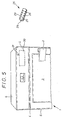
- Fig. 5
- den Oberteil einer anderen Ausführung des Tresorschranks mit Fernbedienung.
- Fig. 1
- the top of a safe cabinet with a closed metal panel in a perspective view;
- Fig. 2
- enlarges the upper corner area of the safe according to FIG. 1 with the cover open and the keypad visible;
- 3, 4
- the receiving space for the bracket, the keypad and the operating mechanism in the upper part of a safe in cross section with the cover closed and open.
- Fig. 5
- the top of another version of the safe with remote control.
Der in den Fig. 1 und 2 dargestellte Tresorschrank 1 besitzt
eine an vertikalen Scharnieren 2 angelenkte Tür 3 und hat
oberhalb seiner - durch Strichlinien angedeuteten - oberen
Deckenpanzerung 4 einen Aufbau 5 von gleicher Breite und
Tiefe wie der eigentliche Tresorkörper. Der Aufbau 5 und der
Tresorkörper haben ein gemeinsames im wesentlichen glattwandiges
Gehäuse 6.The
In der Frontseite des Aufbaus 5 ist eine hochfeste Blende 7,
z.B. aus Stahlblech, angeordnet, die bei der in Fig. 1 dargestellten
Ausführung ein zentrales Namensschild 8 und einen
darin unauffällig integrierten Druckschalter 9 aufweist.In the front of the
Wie aus den Fig. 2 und 4 ersichtlich, wird durch eine Aufschwenkbewegung
der Blende 7 ein Tastenfeld 10 in eine zur
Bedienung zugängliche Stellung gebracht, das eine Vielzahl
von z.B. mit Ziffern oder anderen Symbolen versehenen Tasten
11 und eine als Display ausgeführte optische Anzeige 12 aufweist.
Bei der dargestellten Ausführung ist das Tastenfeld
10 an der Innenseite der Blende 7 starr befestigt, so daß es
bei einer Aufschwenkbewegung der Blende 7 aus der geschützten
inneren Lage nach Fig. 1 in die Bedienungsstellung nach
Fig. 2 gelangt.As can be seen from FIGS. 2 and 4, is by a pivoting movement
the bezel 7 a
Wie aus den Fig. 3, 4 ersichtlich, ist in dem Aufsatz 5 eine
Kammer 15 zur Aufnahme eines Einschubs 16 ausgebildet, in
welchem eine Halterung 17 für die Blende 7 und das Tastenfeld
10 sowie der Betätigungsmechanismus zum Auf- und Einschwenken
der vorgenannten Bauteile in einer gemeinsamen
Rahmenkonstruktion untergebracht sind. Bei der dargestellten
Ausführung enthält der Betätigungsmechanismus ein Federelement
18 in Form einer Schrauben- oder Gasdruck-Feder,
das mit einem Ende am Einschub-Rahmen 19 und mit dem anderen
Ende an einem oberen Punkt der Halterung 17 angreift. Die
Halterung 17 besitzt Seitenwände 20 mit mehreren speziell
geformten Langlöchern 21, 22, in denen an Schwenkhebeln 23,
24 sitzende Zapfen geführt sind und beim Öffnen entsprechende
Bewegungen aus der in Fig. 3 gezeigten Position in diejenige
nach Fig. 4 ausführen. Diese Konstruktion aus Langlöchern
in stabilen Seitenwänden und Winkel-Schwenkhebeln bildet
gleichzeitig eine wirksame Verriegelung für die Blende
7, die aufgrund ihrer bruchfesten Verbindung mit der Halterung
und mit dem Einschubrahmen nur durch große Kraftanwendung
aufgebrochen werden könnte, was jedoch mit einer Beschädigung
des Tastenfeldes und auch der ggf. im Einschub
untergebrachten elektronischen Bauelemente verbunden wäre.
In einem solchen Fall kann dann die Elektronik einen - letzten
- Sperrbefehl an das Verriegelungssystem des Tresorkörpers
ausgeben, durch den dieses System in einen dauerhaften
Sperrzustand versetzt wird.As can be seen from FIGS. 3, 4, there is one in the
Der Tresorschrank nach Fig. 5 entspricht weitgehend der Ausführung
nach Fig. 1. Die Betätigung seines elektro-mechanischen
Verschlußsystems erfolgt bei diesem Ausführungsbeispiel
durch ein Fernbedienungsgerät 25, das - wie dargestellt
- als Handgerät ausgeführt oder auch in eine Wand,
einen Schreibtisch od. dgl. eingebaut sein kann. Auf diesem
Fernbedienungsgerät 25 ist eine Tastatur 26 und eine Anzeige
27 in einem geschlossenen Gehäuse 28 angeordnet. Von einem
Sende-Element 29 werden die über die Tastatur 26 eingegebenen
Anweisungen abgestrahlt.5 largely corresponds to the design
according to Fig. 1. The actuation of its electro-mechanical
Closure system takes place in this embodiment
by a
Im Inneren des Gehäuses 6 ist eine - gestrichelt eingezeichnete
- Elektronik 30 eingebaut, deren Empfangs-Element 31
die vom Sende-Element 29 abgestrahlten Befehle und Anweisungen
empfängt. Die Elektronik 30 verarbeitet diese Befehle in
gleicher Weise wie beim Ausführungsbeispiel nach Fig. 1 zum
Betätigen des Verschlußsystems.Inside the
Die Erfindung ist nicht auf die dargestellte Ausführung beschränkt.
So kann statt den in Fig. 3, 4 dargestellten Federelementen
18 des Betätigungsmechanismus ein motorischer Antrieb
verwendet werden, der die Halterung 17 mit der Blende
7 und dem Tastenfeld 10 aus der in Fig. 3 dargestellten geschlossenen
Stellung in die Betriebsposition nach Fig. 4 - und
umgekehrt - bewegt. Dieses Antriebsaggregat kann über
eine elektronische Steuerung verfügen, die nicht auf eine
Betätigung des Druckschalters 9, sondern auf Befehle einer
sog. Fernbedienung anspricht. Ferner kann der Druckschalter
9 nicht - wie in Fig. 1 dargestellt - an der Blende 7, sondern
auch an einer anderen Stelle des Tresors unauffällig,
z.B. an einer Bodenplatte, angeordnet sein. Schließlich ist
auch eine in das Gehäuse eingesenkte Position der geschlossenen
Blende möglich.The invention is not limited to the embodiment shown.
So instead of the spring elements shown in Fig. 3, 4
18 of the actuating mechanism, a motor drive
be used, the
Claims (11)
dadurch gekennzeichnet, daß
das Tastenfeld (10) im geschlossenen Normalzustand des Tresors in einem geschützten und durch eine verriegelbare Metallblende (7) verschlossenen Aufnahmeraum angeordnet und erst nach Entriegeln und Öffnen der Metallblende (7) zur Befehlseingabe zugänglich ist, wobei die Metallblende (7) an das Design des Tresors derart angepaßt ist, daß sie in ihrer Schließstellung von Unbefugten nicht als solche erkannt werden kann.Safe cabinet consisting of an outer housing with a lock room surrounded by armor and an armored swinging door, a locking system for locking the swinging door and electronics that can be actuated by means of a keypad to actuate the locking system,
characterized in that
the keypad (10) in the closed normal state of the safe is arranged in a protected and locked by a lockable metal panel (7) receiving space and is only accessible after unlocking and opening the metal panel (7) for entering commands, the metal panel (7) to the design of the The safe is adapted in such a way that it cannot be recognized as such by unauthorized persons in its closed position.
dadurch gekennzeichnet, daß
das Tastenfeld (10) zusammen mit der optischen Anzeige (12) auf einer im Aufnahmeraum (15) beweglich angeordneten Halterung (17) fest montiert ist.Safe cabinet according to claim 1,
characterized in that
the keypad (10) together with the optical display (12) is fixedly mounted on a holder (17) which is movably arranged in the receiving space (15).
dadurch gekennzeichnet, daß
das Tastenfeld (10) zusammen mit der optischen Anzeige (12) an einer im Aufnahmeraum (15) fest installierten Halterung montiert und lediglich die Blende (7) bewegbar ausgebildet ist.Safe cabinet according to claim 1,
characterized in that
the keypad (10) is mounted together with the optical display (12) on a holder permanently installed in the receiving space (15) and only the cover (7) is designed to be movable.
dadurch gekennzeichnet, daß
die den Aufnahmeraum (15) fest verschließende Blende (7) an das Design des Tresors (1) derart angepaßt ist, daß die Blende in ihrer Schließstellung nicht als solche erkannt werden kann.Safe cabinet according to one of claims 1 to 3,
characterized in that
the cover (7) which closes the receiving space (15) is adapted to the design of the safe (1) in such a way that the cover in its closed position cannot be recognized as such.
dadurch gekennzeichnet, daß
die Blende (7) nach unten verschwenkbar ist und an ihrer Innenseite das Tastenfeld (10) zusammen mit der optischen Anzeige (12) trägt.Safe cabinet according to one of Claims 1, 2 and 4,
characterized in that
the panel (7) can be pivoted downwards and on its inside carries the keypad (10) together with the optical display (12).
dadurch gekennzeichnet, daß
ein Schalter (9) zum Lösen der Blendenverriegelung und zum Bewegen der Blende (7) in ihre Öffnungs- bzw. Schließstellung vorgesehen ist.Safe cabinet according to one of claims 1 to 5,
characterized in that
a switch (9) for releasing the panel lock and for moving the panel (7) into its open or closed position is provided.
dadurch gekennzeichnet, daß
der Bewegungsmechanismus für die Halterung (17), die Blende (7) und das Tastenfeld (10) mittels einer Fernbedienung betätigbar ist.Safe cabinet according to one of claims 1 to 6,
characterized in that
the movement mechanism for the holder (17), the panel (7) and the keypad (10) can be operated by means of a remote control.
dadurch gekennzeichnet, daß
der Aufnahmeraum (15) für die Halterung (17), das Tastenfeld (10) und den Betätigungsmechanismus vom Tresor-Innenraum getrennt außerhalb der Panzerung (4) angeordnet ist.Safe cabinet according to one of claims 1 to 7,
characterized in that
the receiving space (15) for the holder (17), the keypad (10) and the actuating mechanism is arranged separately from the interior of the safe outside the armor (4).
dadurch gekennzeichnet, daß
die Blende (7) mittels Federkraft entriegelbar und bewegbar ist.Safe cabinet according to one of claims 1 to 8,
characterized in that
the cover (7) can be unlocked and moved by means of spring force.
dadurch gekennzeichnet, daß
die Blende (7) motorisch ent- bzw. verriegelbar und bewegbar ist. Safe cabinet according to one of claims 1 to 8,
characterized in that
the panel (7) can be locked and moved by a motor and moved.
dadurch gekennzeichnet, daß
characterized in that
Applications Claiming Priority (2)
| Application Number | Priority Date | Filing Date | Title |
|---|---|---|---|
| DE1997129357 DE19729357C2 (en) | 1997-07-09 | 1997-07-09 | Safe cabinet |
| DE19729357 | 1997-07-09 |
Publications (2)
| Publication Number | Publication Date |
|---|---|
| EP0890697A2 true EP0890697A2 (en) | 1999-01-13 |
| EP0890697A3 EP0890697A3 (en) | 2004-10-06 |
Family
ID=7835150
Family Applications (1)
| Application Number | Title | Priority Date | Filing Date |
|---|---|---|---|
| EP98112574A Withdrawn EP0890697A3 (en) | 1997-07-09 | 1998-07-07 | Safe |
Country Status (2)
| Country | Link |
|---|---|
| EP (1) | EP0890697A3 (en) |
| DE (1) | DE19729357C2 (en) |
Cited By (4)
| Publication number | Priority date | Publication date | Assignee | Title |
|---|---|---|---|---|
| CN102071861A (en) * | 2011-01-26 | 2011-05-25 | 陈军彪 | Electronic panel of safe box |
| CN102852401A (en) * | 2012-09-28 | 2013-01-02 | 永康市王力五金制造有限公司 | Concealed keyboard device of electronic lock |
| CN104278909A (en) * | 2014-09-18 | 2015-01-14 | 宁波艾谱实业有限公司 | Panel device of strongbox cabinet |
| EP2855311B1 (en) * | 2012-05-31 | 2020-07-29 | Weidmüller Interface GmbH & Co. KG | Printer having a separating device |
Citations (3)
| Publication number | Priority date | Publication date | Assignee | Title |
|---|---|---|---|---|
| DE7024466U (en) | 1970-06-30 | 1970-11-19 | Mauser Werke Gmbh | SAFE DEPOSIT |
| US4669394A (en) | 1985-03-26 | 1987-06-02 | Fogleman H Frank | Safes |
| DE9407802U1 (en) | 1994-05-13 | 1994-07-07 | Garny Sicherheitstechn Gmbh | Compartment unit |
Family Cites Families (1)
| Publication number | Priority date | Publication date | Assignee | Title |
|---|---|---|---|---|
| AT373665B (en) * | 1982-07-29 | 1984-02-10 | Wertheim Werke Ag | MONEY CABINET WITH A MISUSE PROTECTION |
-
1997
- 1997-07-09 DE DE1997129357 patent/DE19729357C2/en not_active Expired - Lifetime
-
1998
- 1998-07-07 EP EP98112574A patent/EP0890697A3/en not_active Withdrawn
Patent Citations (3)
| Publication number | Priority date | Publication date | Assignee | Title |
|---|---|---|---|---|
| DE7024466U (en) | 1970-06-30 | 1970-11-19 | Mauser Werke Gmbh | SAFE DEPOSIT |
| US4669394A (en) | 1985-03-26 | 1987-06-02 | Fogleman H Frank | Safes |
| DE9407802U1 (en) | 1994-05-13 | 1994-07-07 | Garny Sicherheitstechn Gmbh | Compartment unit |
Cited By (6)
| Publication number | Priority date | Publication date | Assignee | Title |
|---|---|---|---|---|
| CN102071861A (en) * | 2011-01-26 | 2011-05-25 | 陈军彪 | Electronic panel of safe box |
| CN102071861B (en) * | 2011-01-26 | 2012-04-04 | 陈军彪 | Electronic panel of safe box and lockage method |
| EP2855311B1 (en) * | 2012-05-31 | 2020-07-29 | Weidmüller Interface GmbH & Co. KG | Printer having a separating device |
| CN102852401A (en) * | 2012-09-28 | 2013-01-02 | 永康市王力五金制造有限公司 | Concealed keyboard device of electronic lock |
| CN102852401B (en) * | 2012-09-28 | 2015-03-25 | 永康市王力五金制造有限公司 | Concealed keyboard device of electronic lock |
| CN104278909A (en) * | 2014-09-18 | 2015-01-14 | 宁波艾谱实业有限公司 | Panel device of strongbox cabinet |
Also Published As
| Publication number | Publication date |
|---|---|
| DE19729357C2 (en) | 2000-06-29 |
| EP0890697A3 (en) | 2004-10-06 |
| DE19729357A1 (en) | 1999-01-14 |
Similar Documents
| Publication | Publication Date | Title |
|---|---|---|
| DE202011110685U1 (en) | cashbox | |
| DE19603200C2 (en) | Electronic door lock | |
| EP2169154A2 (en) | Door terminal | |
| DE19729357C2 (en) | Safe cabinet | |
| CH647838A5 (en) | DEVICE FOR SEPARATING OF PERSONS IN ORDER TO PREVENT UNAUTHORIZED ACCESS CONTROL IN THE rooms behind. | |
| DE102014104823A1 (en) | Electronic locking device | |
| DE4316274C1 (en) | Device for the locking of furniture doors | |
| DE10062466B4 (en) | Electronic lock, locking system and method for opening and / or closing an electronic lock | |
| DE2912253A1 (en) | LOCKER WITH LOCK ON THE REAR | |
| DE102010053893B4 (en) | Security gate with access badge | |
| DE10114271A1 (en) | Valuables strong room for areas without suitable buildings has protective room containing magazine and dividing wall containing access hatch arranged in transportable strong room housing | |
| DE19754110C2 (en) | locker system | |
| EP0000744B1 (en) | Safe for the storage of keys | |
| DE19807172A1 (en) | Housing for self accounting vending or service machine esp. ticket machine or parking voucher machine | |
| DE4304356C1 (en) | Security access gate for people with bicycles - has access opening adjacent to access gate for people formed from cage-type component with electrically bolted doors on each end. | |
| DE2630019A1 (en) | Lock for vault or safe - has hollow solenoids and electronically controlled circuits operated externally from keyboard | |
| DE3414393A1 (en) | Device for protecting rooms against attack and the taking of hostages | |
| AT413845B (en) | CASTLE OF CHEST, CABIN, DOORS | |
| DE202014003861U1 (en) | Locker system with a plurality of lockers | |
| DE202007003851U1 (en) | Keyless lock in particular for securing window or furniture door, comprises only two push buttons for input of code | |
| DE7234089U (en) | ADDITIONAL DOOR PROVIDED IN A STEEL OR TANK CABINET | |
| DE3633521A1 (en) | Sluice for containers | |
| EP1052350A1 (en) | Escutcheon for doors | |
| DE10008349A1 (en) | Locking mechanism for kitchen furniture has a cable-operated locking bolt acting on a limit to lock or release extensions or flaps or doors and prevent access by small children | |
| DE102004039597A1 (en) | Vending machine, in particular parking ticket machine |
Legal Events
| Date | Code | Title | Description |
|---|---|---|---|
| PUAI | Public reference made under article 153(3) epc to a published international application that has entered the european phase |
Free format text: ORIGINAL CODE: 0009012 |
|
| AK | Designated contracting states |
Kind code of ref document: A2 Designated state(s): AT BE CH CY DE DK ES FI FR GB GR IE IT LI LU MC NL PT SE |
|
| AX | Request for extension of the european patent |
Free format text: AL;LT;LV;MK;RO;SI |
|
| PUAL | Search report despatched |
Free format text: ORIGINAL CODE: 0009013 |
|
| AK | Designated contracting states |
Kind code of ref document: A3 Designated state(s): AT BE CH CY DE DK ES FI FR GB GR IE IT LI LU MC NL PT SE |
|
| AX | Request for extension of the european patent |
Extension state: AL LT LV MK RO SI |
|
| RIC1 | Information provided on ipc code assigned before grant |
Ipc: 7G 07C 9/00 B Ipc: 7E 05B 49/00 B Ipc: 7E 05B 47/00 B Ipc: 7E 05G 1/02 A |
|
| 17P | Request for examination filed |
Effective date: 20050310 |
|
| RAP1 | Party data changed (applicant data changed or rights of an application transferred) |
Owner name: STOCKINGER SAFETY FIRST CLASS GMBH |
|
| RAP1 | Party data changed (applicant data changed or rights of an application transferred) |
Owner name: STOCKINGER SAFETY FIRST CLASS GMBH |
|
| AKX | Designation fees paid |
Designated state(s): AT CH DE ES FR GB IT LI |
|
| 17Q | First examination report despatched |
Effective date: 20071005 |
|
| STAA | Information on the status of an ep patent application or granted ep patent |
Free format text: STATUS: THE APPLICATION IS DEEMED TO BE WITHDRAWN |
|
| 18D | Application deemed to be withdrawn |
Effective date: 20090430 |