EP0890433B1 - Rotary valve in a sheet feeding unit of an offset printing press - Google Patents
Rotary valve in a sheet feeding unit of an offset printing press Download PDFInfo
- Publication number
- EP0890433B1 EP0890433B1 EP19980250235 EP98250235A EP0890433B1 EP 0890433 B1 EP0890433 B1 EP 0890433B1 EP 19980250235 EP19980250235 EP 19980250235 EP 98250235 A EP98250235 A EP 98250235A EP 0890433 B1 EP0890433 B1 EP 0890433B1
- Authority
- EP
- European Patent Office
- Prior art keywords
- air
- air passage
- valve body
- suction
- hollow portion
- Prior art date
- Legal status (The legal status is an assumption and is not a legal conclusion. Google has not performed a legal analysis and makes no representation as to the accuracy of the status listed.)
- Expired - Lifetime
Links
Images




Classifications
-
- F—MECHANICAL ENGINEERING; LIGHTING; HEATING; WEAPONS; BLASTING
- F16—ENGINEERING ELEMENTS AND UNITS; GENERAL MEASURES FOR PRODUCING AND MAINTAINING EFFECTIVE FUNCTIONING OF MACHINES OR INSTALLATIONS; THERMAL INSULATION IN GENERAL
- F16K—VALVES; TAPS; COCKS; ACTUATING-FLOATS; DEVICES FOR VENTING OR AERATING
- F16K5/00—Plug valves; Taps or cocks comprising only cut-off apparatus having at least one of the sealing faces shaped as a more or less complete surface of a solid of revolution, the opening and closing movement being predominantly rotary
- F16K5/04—Plug valves; Taps or cocks comprising only cut-off apparatus having at least one of the sealing faces shaped as a more or less complete surface of a solid of revolution, the opening and closing movement being predominantly rotary with plugs having cylindrical surfaces; Packings therefor
- F16K5/0407—Plug valves; Taps or cocks comprising only cut-off apparatus having at least one of the sealing faces shaped as a more or less complete surface of a solid of revolution, the opening and closing movement being predominantly rotary with plugs having cylindrical surfaces; Packings therefor with particular plug arrangements, e.g. particular shape or built-in means
-
- B—PERFORMING OPERATIONS; TRANSPORTING
- B65—CONVEYING; PACKING; STORING; HANDLING THIN OR FILAMENTARY MATERIAL
- B65H—HANDLING THIN OR FILAMENTARY MATERIAL, e.g. SHEETS, WEBS, CABLES
- B65H3/00—Separating articles from piles
- B65H3/08—Separating articles from piles using pneumatic force
- B65H3/0808—Suction grippers
- B65H3/0891—Generating or controlling the depression
-
- B—PERFORMING OPERATIONS; TRANSPORTING
- B65—CONVEYING; PACKING; STORING; HANDLING THIN OR FILAMENTARY MATERIAL
- B65H—HANDLING THIN OR FILAMENTARY MATERIAL, e.g. SHEETS, WEBS, CABLES
- B65H2557/00—Means for control not provided for in groups B65H2551/00 - B65H2555/00
- B65H2557/30—Control systems architecture or components, e.g. electronic or pneumatic modules; Details thereof
- B65H2557/37—Control systems architecture or components, e.g. electronic or pneumatic modules; Details thereof for fluid control
- B65H2557/371—Rotary valve
-
- Y—GENERAL TAGGING OF NEW TECHNOLOGICAL DEVELOPMENTS; GENERAL TAGGING OF CROSS-SECTIONAL TECHNOLOGIES SPANNING OVER SEVERAL SECTIONS OF THE IPC; TECHNICAL SUBJECTS COVERED BY FORMER USPC CROSS-REFERENCE ART COLLECTIONS [XRACs] AND DIGESTS
- Y10—TECHNICAL SUBJECTS COVERED BY FORMER USPC
- Y10T—TECHNICAL SUBJECTS COVERED BY FORMER US CLASSIFICATION
- Y10T137/00—Fluid handling
- Y10T137/8593—Systems
- Y10T137/86389—Programmer or timer
- Y10T137/86405—Repeating cycle
-
- Y—GENERAL TAGGING OF NEW TECHNOLOGICAL DEVELOPMENTS; GENERAL TAGGING OF CROSS-SECTIONAL TECHNOLOGIES SPANNING OVER SEVERAL SECTIONS OF THE IPC; TECHNICAL SUBJECTS COVERED BY FORMER USPC CROSS-REFERENCE ART COLLECTIONS [XRACs] AND DIGESTS
- Y10—TECHNICAL SUBJECTS COVERED BY FORMER USPC
- Y10T—TECHNICAL SUBJECTS COVERED BY FORMER US CLASSIFICATION
- Y10T137/00—Fluid handling
- Y10T137/8593—Systems
- Y10T137/86493—Multi-way valve unit
- Y10T137/86574—Supply and exhaust
- Y10T137/86638—Rotary valve
- Y10T137/86646—Plug type
- Y10T137/86654—For plural lines
-
- Y—GENERAL TAGGING OF NEW TECHNOLOGICAL DEVELOPMENTS; GENERAL TAGGING OF CROSS-SECTIONAL TECHNOLOGIES SPANNING OVER SEVERAL SECTIONS OF THE IPC; TECHNICAL SUBJECTS COVERED BY FORMER USPC CROSS-REFERENCE ART COLLECTIONS [XRACs] AND DIGESTS
- Y10—TECHNICAL SUBJECTS COVERED BY FORMER USPC
- Y10T—TECHNICAL SUBJECTS COVERED BY FORMER US CLASSIFICATION
- Y10T137/00—Fluid handling
- Y10T137/8593—Systems
- Y10T137/86493—Multi-way valve unit
- Y10T137/86574—Supply and exhaust
- Y10T137/86638—Rotary valve
- Y10T137/86646—Plug type
- Y10T137/86662—Axial and radial flow
Definitions
- the present invention relates to a rotary valve disposed between intake and exhaust air sources and suction and discharge units, to supply or stop supplying air.
- a suction unit connected to an intake air source and a discharge unit connected to an exhaust air source are used to feed stacked sheets to the feeder board one by one. More specifically, in order to draw the highest sheet by suction with the suction unit, the air of the suction unit is taken by an intake pump serving as the intake air source. In order to blow air to the stacked sheets or to separate the highest sheet drawn by the suction unit and the second sheet from each other, or in order to discharge reverse air that facilitates separation of the sheet conveyed from the suction unit to the feeder board, exhaust air is supplied by an exhaust pump serving as the exhaust air source.
- the ON/OFF timings of each of the intake air and exhaust air correspond to the rotation angle of the printing press main body. This series of timings is controlled by a rotary valve.
- Fig. 9 shows a conventional rotary valve.
- a main body 2 formed into a substantially rectangular parallelepiped shape is fixed to a frame 5 of a sheet feeding unit through a bracket 5a.
- the first and second suckers, a leveling foot, and an air blower (not shown) are provided to the sheet feeding unit.
- the lower portion of the main body 2 in one end side in the direction of an arrow Y swells in an arcuated manner to constitute a swelling portion 2a.
- a through hole 3 extending in the direction of an arrow X is formed in the swelling portion 2a, and a cylindrical sleeve 4 is fixed to the inner circumferential surface of the through hole 3.
- a valve body 6 is engaged in the sleeve 4. End shafts 6a and 6b on the two ends of the valve body 6 are rotatably supported by the sleeve 4 through bearings 7a and 7b. The valve body 6 rotates in an interlocked manner with rotation of the printing press through one end shaft 6a.
- air passages 9a, 9b, 9c, and 9d are formed in the upper portion side of the main body 2 corresponding to the swelling portion 2a, to extend in the vertical direction (the direction of an arrow Z).
- the air passages 9a to 9d are connected to an intake pump (to be described later) through hoses 17a and 17b.
- the air passages 9a and 9b constitute an intake air passage.
- the air passages 9c and 9d, on their upper end side, are connected to an exhaust pump (to be described later) through hoses 17c and 18d.
- the air passages 9c and 9d constitute an exhaust air passage.
- Air passages 10a, 10b, 10c, and 10d are formed in the main body 2 to extend in the direction of the arrow Y perpendicularly to the intake air passages 9a and 9b and the exhaust air passages 9c and 9d, respectively.
- One end of each of the air passages 10a to 10d opens to the outside of the main body 2 while the other end thereof communicates with the through hole 3.
- the air passages 10a to 10d are connected to suction heads (to be described later), serving as the first and second suckers, through hoses 18a and 18b.
- the air passages 10a and 10b constitute a suction air passage.
- the air passages 10c and 10d are connected to nozzles (to be described later), respectively serving as a leveling food and an air blower, through hoses 18c and 18d.
- the air passages 10c and 10d constitute a discharge air passage.
- Reference numeral 31 denotes a reverse air passage for the suction heads.
- the reverse air passage 31 is formed between the suction air passages 10a and 10b to extend from the upper end of the main body 2 to the circumferential surface of the valve body 6 through the sleeve 4.
- the exhaust pump (described above) is connected to the upper opening end side of the reverse air passage 31 through a hose (not shown).
- the lower end of the reverse air passage 31 communicates with the suction air passages 10a and 10b through a notch (to be described later) formed in the valve body 6.
- Vent holes 11a, 11b, 11c, and 11d are formed in the sleeve 4 to respectively correspond to the intake air passages 9a and 9b and the exhaust air passages 9c and 9d. Vent holes 12a, 12b, 12c, and 12d are also formed in the sleeve 4 to respectively correspond to the suction air passages 10a and 10b and the discharge air passages 10c and 10d.
- a notch 13a through which the vent holes 11a and 12a communicate with each other is formed in the circumferential surface of the valve body 6 corresponding to the intake air passage 9a and the suction air passage 10a.
- a notch 13b through which the vent holes 11b and 12b communicate with each other is formed in the circumferential surface of the valve body 6 corresponding to the intake air passage 9b and the suction air passage 10b, at a position displaced from the notch 13a in the axial direction and to be phase-shifted from the notch 13a in the rotating direction of the valve body 6.
- a notch 13c through which the vent holes 11c and 12c communicate with each other is formed in the circumferential surface of the valve body 6 corresponding to the intake air passage 9c and the suction air passage 10c.
- a notch 13d through which the vent holes lid and 12d communicate with each other is formed in the circumferential surface of the valve body 6 corresponding to the intake air passage 9d and the suction air passage 10d, at a position displaced from the notch 13c in the axial direction and to be phase-shifted from the notch 13c in the rotating direction of the valve body 6.
- the notch 13d of the valve body 6 opposes the vent holes 11d and 12d of the sleeve 4, and the exhaust air passage 9d and the discharge air passage 10d communicate with each other through the notch 13d.
- air exhausted from the exhaust pump flows through the air passages 9d and 10d that communicate with each other through the notch 13d, and is discharged from the nozzles to blow air to the sheets.
- the notch 13b opposes the vent holes 11b and 12b, and the intake air passage 9b and the suction air passage 10b communicate with each other through the notch 13b.
- the intake air taken by the intake pump flows through the air passages 9b and 10b that communicate with each other through the notch 13b, to draw a sheet by suction with the second sucker.
- the notch 13a is displaced from the vent hole 12a, and the intake air passage 9a and the suction air passage 10a are disconnected from each other.
- suction air supply is stopped, and the sheet suction operation with the first sucker is stopped.
- a notch 32a of the valve body 6 opposes the reverse air passage 31, the reverse air passage 31 and the suction air passage 10a communicate with each other through the notch 32a.
- the exhaust air exhausted from the exhaust pump flows through the air passages 31 and 10a and is blown out from the first sucker, and the sheet is quickly released from the first sucker that has ended the suction operation.
- a sheet which is conveyed to above the feeder board while being drawn by the second sucker will not be cut or bent.
- the notch 13b is displaced from the vent hole 12b in accordance with rotation of the valve body 6, and the intake air passage 9b and the suction air passage 10b are disconnected from each other.
- intake air supply is stopped, and the sheet suction operation with the second sucker is stopped.
- a notch 32b opposes the reverse air passage 31, and the reverse air passage 31 and the suction air passage 10b communicate with each other through the notch 32b.
- the exhaust air exhausted from the exhaust pump flows through the air passages 31 and 10b and is blown out from the second sucker.
- the sheet is quickly released from the second sucker that has ended the suction operation, and is supplied to above the feeder board.
- the notch 13c constituting the air passage from the exhaust pump is formed smaller than the notch 13a constituting the air passage from the intake pump, as shown in Figs. 10A and 10B.
- the notch 13a is formed smaller than the notch 13c, as shown in Figs. 12A and 12B.
- the amount of air from the nozzles becomes short and air blowing to the stacked sheets is not performed sufficiently, and two or more sheets are undesirably drawn by the suction heads.
- operation of the printing press must be stopped, or the printing press may cause a trouble to decrease the productivity. Since the supply amount of reverse air from the suction heads becomes short to delay sheet release from the suction heads, the sheet may be cut or bent to degrade the printing quality.
- notch 13a is made small to shorten the suction time of the suction heads, along with rotation of the valve body 6, as the opening of the vent hole 11a is enlarged, the opening of the vent hole 12a is narrowed. As a result, a predetermined air pressure cannot be obtained with the suction heads, and defective sheet supply may occur.
- Fig. 11 shows the relationship in pressure of the input/output air of the rotary valve of Fig. 10B during the discharge operation.
- reference numeral b1 denotes the pressure of the exhaust air input to the rotary valve 30.
- the pressure b1 is the pressure of the exhaust air from the exhaust pump.
- Reference numeral b2 denotes the pressure of the discharge air output from the rotary valve.
- the pressure b2 is the pressure of the discharge air from the nozzles.
- the notch 13c of the valve body 6 opposes the vent holes 11c and 12c of the sleeve 4, and discharge air is supplied from an exhaust pump 36 to the nozzles through the exhaust air passage 9c, the notch 13c, and the discharge air passage 10c.
- the pressure of air supplied to the nozzles at this time is expressed as a pressure P.
- the notch 13c is displaced from the vent hole 12c, the vent hole 12c is closed with the circumferential surface of the valve body 6, and supply of the discharge air to the discharge air passage 10c is stopped.
- a pressure b3 of the discharge air between the machine angles ⁇ 1 and ⁇ 2 of rotation becomes lower than a necessary pressure b4 by a pressure difference ⁇ P. This is due to the following reason. Since the notch 13c is small, along with rotation of the valve body 6, as the opening of the vent hole 11c is enlarged, the opening of the vent hole 12c is narrowed, so the air exhausted from the exhaust pump 36 is not sufficiently supplied to the nozzles.
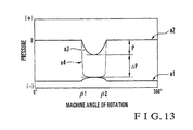
- Fig. 13 shows the relationship of the input/output air of the rotary valve shown in Fig. 12A during the suction operation. As shown in Fig. 13, even during the suction operation, a pressure loss in air of the rotary valve occurs.
- Reference numeral a1 denotes the pressure of the intake air input to the rotary valve 30. The pressure a1 is the pressure of intake air from the intake pump.
- Reference numeral a2 denotes the pressure of the suction air output from the rotary valve 30.
- the pressure a2 is the pressure of the suction air of the suction heads.
- a pressure a3 of the suction air between the machine angles ⁇ 1 and ⁇ 2 of rotation becomes higher than a necessary pressure a4 by a pressure difference ⁇ P.
- Document DE-A-4 215 226 discloses a rotary valve in which the compressed air source and the hollow portion are connected through a hole extending towards a radial direction of valve body and whole of a main body. Therefore, the compressed air sources.in the hollow portion are either disconnected or connected from each other by a rotation the valve body.
- the opening in the rotary valve according to the mentioned document is in the circumferential surface of the valve body. This means that the opening and air source on the circumferential surface of the valve are intermittently connected to each other, where the intermittence is subjected to the rotation of the valve body. In a structure where the intermittence is subject to the rotation of the valve body, the air flow is interrupted.
- Document US-A-3 884 460 shows a spool valve member in which a chamber is formed along the central axis. Pressurized air supplied into the chamber flows into the outlet channel through the radial bores, so as to provide a blast to the suction cup. Pressurized air is supplied into the chamber in a radial direction, i.e. through the supply channel, the inlet opening and the distribution channel.
- Document DE-195 15 301 relates to an arrangement for controlling air with an air diffuser comprising a controller cylinder which is pivotably driveable during a cycle, which, with its cylindrical shell surface, is pivotably run on bearings in the bore hole of a control bearing bush which closely surrounds the controller cylinder, whereby the controller cylinder discloses an air admittable inner chamber from which radial control recesses lead to the cylindrical shell surface of the controller cylinder, which, with radial control connections formed in the control socket/liner, can be overlapped.
- a rotary valve which is interposed between a first and a second air source for supplying air, and at least one air unit that performs a predetermined operation upon reception of the air supplied from the first and second air sources, to supply/stop supplying air, comprising a valve body rotatably driven in a cylinder, a main body for rotatably supporting the valve body, notches formed in a circumferential surface of the valve body, to be connected to the first air source, and further comprising a first hollow portion formed in said valve body, and wherein said rotary valve comprises a first air passage formed in said main body and having one end side connected to said first air source and the other end side that opens in an inner circumferential surface of said cylinder, a second air passage formed in said main body and having one end side connected to the first air unit and the other end side that opens in said inner circumferential surface of said cylinder, said first air passage being connected to said second air passage through said notches and a first air passage formed in said main body and having one end side connected to said first air
- main body having one end side connected to the second air unit and the other end side that opens in an inner circumferential surface of said cylinder, a second hollow portion formed in said valve body in an axial direction and connected to said first air source, and a second communication hole formed in said valve body to connect said second hollow portion and said third air passage to each other.
- Fig. 3 shows the schematic arrangement of a sheet feeding unit for a printing press.
- the air source side of a rotary valve 101 is connected to an intake pump 134 serving as an intake air source, and an exhaust pump 136 serving as an exhaust air source, through hoses 117a and 117b, and a hose 119, respectively.
- the suction/discharging side of the rotary valve 101 is connected to suction heads 135a and 135b serving as the suction units, and nozzles 137a and 137b serving as the discharge unit, through hoses 118a and 118b, and hoses 118c and 118d, respectively.
- the suction heads 135a and 135b serve as the first and second suckers of the sheet feeding unit, and the nozzles 137a and 137b serve as a leveling food and an air blower.
- Fig. 1 shows the rotary valve shown in Fig. 3.
- a main body 102 formed into a substantially rectangular parallelepiped shape is fixed to a frame 105 of the sheet feeding unit through a bracket 105a.
- the lower portion of the main body 102 in one end side in the direction of an arrow Y swells in an arcuated manner to constitute a swelling portion 102a.
- a through hole 103 extending in the direction of an arrow X is formed in the swelling portion 102a, and a cylindrical sleeve 104 is fixed to the inner surface of the through hole 103.
- a valve body 106 is engaged in the sleeve 104. End shafts 106a and 106b on the two ends of the valve body 106 are rotatably supported by the sleeve 104 through bearings 107a and 107b. The valve body 106 rotates in an interlocked manner with rotation of the printing press through one end shaft 106a.
- Two air passages 109a and 109b are formed in the upper portion side of the main body 102 corresponding to the swelling portion 102a, to extend in the vertical direction (the direction of an arrow Z).
- the air passages 109a and 109b on their upper end side, are connected to the intake pump 134 through the hoses 117a and 117b, and the air passages 109a and 109b constitute an intake air passage (air passage for the intake air source).
- Air passages 110a and 110b are formed in the main body 102 to extend in the direction of the arrow Y perpendicularly to the intake air passages 109a and 109b. Also, air passages 110c and 110d are formed in parallel to the air passages 110a and 110b. One end of each of the air passages 110a to 110d opens to the outside of the main body 102 while the other end thereof is connected to the through hole 103.
- the air passages 110a and 110b are connected to the suction heads 135a and 135b through the hoses 118a and 118b, as described above.
- the air passages 110a and 110b constitute a suction air passage (air passage for the suction unit).
- the air passages 110c and 110d are connected to the nozzles 137a and 137b through the hoses 118c and 118d, and the air passages 110c and 110d constitute a discharge air passage (air passage for the discharge unit).
- Vent holes 111a and 111b are formed in the sleeve 104 to respectively correspond to the intake air passages 109a and 109b. Vent holes 112a, 112b, 112c, and 112d are also formed in the sleeve 104 to respectively correspond to the suction air passages 110a and 110b and the discharge air passages 110c and 110d.
- a blind hole-like hollow portion 114 is formed in the valve body 106 to have an opening in the end face of the valve body 106 on one end shaft 106b side and to extend in the direction of an arrow X to a position corresponding to the intake air passage 109a.
- the exhaust pump 136 is connected to the opening side of the hollow portion 114 through the hose 119. Accordingly, the hollow portion 114 constitutes an exhaust air passage (air passage for the exhaust air source).
- a communication hole 115a (Fig. 2A) is formed in the valve body 106.
- the communication hole 115a allows the hollow portion 114 to communicate with the suction air passage 110a through the vent hole 112a.
- a communication hole 115b is formed in the valve body 106 at a position displaced from the communication hole 115a in the axial direction and to be phase-shifted from the communication hole 115a in the rotating direction.
- the communication hole 115b allows the hollow portion 114 to communicate with the suction air passage 110b through the vent hole 112b.
- a communication hole 115c (Fig. 2B) is formed in the valve body 106.
- the communication hole 115c allows the hollow portion 114 to communicate with the discharge air passage 110c through the vent hole 112c.
- a communication hole 115d is formed in the valve body 106 at a position displaced from the communication hole 115c in the axial direction and to be phase-shifted from the communication hole 115c in the rotating direction.
- the communication hole 115d allows the hollow portion 114 to communicate with the discharge air passage 110d through the vent hole 112d.
- a notch 113a through which the vent holes 111a and 112a communicate with each other is formed in the circumferential surface of the valve body 106 corresponding to the intake air passage 109a and the suction air passage 110a.
- a notch 113b through which the vent holes 111b and 112b communicate with each other is formed in the circumferential surface of the valve body 106 corresponding to the intake air passage 109b and the suction air passage 110b, at a position displaced from the notch 113a in the axial direction and to be phase-shifted from the notch 113a in the rotating direction of the valve body 106.
- the characteristic feature of this embodiment resides in that the blind hole-like hollow portion 114 having a circular section is formed in the valve body 106 to extend in the axial direction and that this hollow portion 114 serves as the exhaust air passage.
- the conventional exhaust air passages 9c and 9d and reverse air passage 31 shown in Fig. 9 and Figs. 10A and 10B are replaced with the hollow portion 114, so that the reverse air passage 31 and the notches 32a and 32b formed in the valve body 6 become unnecessary.
- valve body 106 When the valve body 106 is rotated in an interlocked manner with rotation of the printing press, the communication hole 115d of the valve body 106 opposes the vent hole 112d of the sleeve 104, and the hollow portion 114 serving as the exhaust air passage and the discharge air passage 110d communicate with each other through the communication hole 115d and the vent hole 112d. Therefore, exhaust air from the exhaust pump 136 flows through the hollow portion 114 and the air passage 110d, and is discharged from the nozzle 137b to blow the air to the sheets (step S11).
- the communication hole 115c opposes the vent hole 112c of the sleeve 104, and the hollow portion 114 serving as the exhaust air passage and the discharge air passage 110c communicate with each other through the communication hole 115c and a vent hole 111c, as shown in Fig. 2B.
- Exhaust air B from the exhaust pump 134 is supplied to the nozzle 137a, serving as the leveling foot, through the hollow portion 114 and the air passage 110c. The air is blown to a portion between the highest sheet and the second sheet, to separate them from each other (step S13).
- the communication hole 115a of the valve body 106 opposes the vent hole 112a, and the hollow portion 114 and the suction air passage 110a communicate with each other through the communication hole 115a and the vent hole 112a.
- the exhaust air from the exhaust pump 136 is supplied to the suction head 135a, serving as the first sucker, through the hollow portion 114 and the air passage 110a.
- the sheet is quickly released from the suction head 135a that has ended the suction operation (step S15). As a result, a sheet which is conveyed to above the feeder board while being drawn by the suction head 135b, serving as the second sucker will not be cut or bent.
- the suction head 135b during sheet conveyance is located above the feeder board, as the valve body 106 is rotated, the communication hole 115b opposes the vent hole 112b, and the hollow portion 114 and the suction air passage 110b communicate with each other through the communication hole 115b and vent hole 112b.
- the exhaust air from the exhaust pump 136 is supplied to the suction head 135b through the hollow portion 114 and the air passage 110b.
- the sheet is quickly released from the suction head 135b, and is supplied onto the feeder board (step S16).
- the air is supplied from the exhaust pump 136 to the nozzles 137a and 137b through the hollow portion 114 and the communication holes 115c and 115d. Therefore, the air blowing and leveling foot operation can be reliably performed within a short period of time with sufficiently high-pressurized air.
- the hollow portion 114, the communication holes 115c and 115d, the vent holes 111c and 111d, and the discharge air passages 110c and 110d are located in a substantially straight line, so that the air loss during the leveling foot operation and air blowing is decreased. Therefore, an exhaust pump having a comparatively small power can be used.
- the exhaust air is supplied through the hollow portion 114 of the valve body 106 which has a large sectional area, the pressure loss of the air at the valve portion is decreased. Also, the exhaust air passages 9c and 9d conventionally formed in the main body 2 or the vent holes 11c and lid conventionally formed in the sleeve 4 become unnecessary, and only the hollow portion 114 and the communication holes 115a to 115d need be formed in the valve body 106. Therefore, the structure is simplified and machining becomes easy.
- Fig. 4 shows a rotary valve according to the first embodiment of the present invention.
- Fig. 5A shows a section taken along the line III- III of Fig. 4
- Fig. 5B shows section taken along'the line IV - IV of Fig. 4.
- Fig. 4 and Figs. 5A and 5B portions that are identical to those of Fig. 1 and Figs. 2A and 2B are denoted by the same reference numerals as in Fig. 1 and Figs. 2A and 2B, and a detailed description thereof will be omitted.
- the first embodiment is different from the embodiment shown in Fig 1 in that, as shown in Fig. 4, a partition wall 114c is formed at the center of a hollow portion 114 to divide the hollow portion 114 into a first hollow portion 114a and a second hollow portion 114b.
- the first hollow portion 114a is connected to an intake pump 134 through a hose 119a to constitute an intake air passage.
- the second hollow portion 114b is connected to an exhaust pump 136 through a hose 119b, in the same manner as in the first embodiment.
- Air passages 116a and 116b formed in the upper end side of a main body 102 are connected to the exhaust pump 136 through hoses 117a and 117b to constitute an exhaust air passage.
- a communication hole 215a (Fig. 5A), where the hollow portion 114 extends to communicate with a suction air passage 110a through a vent hole 112a, is formed in the valve body 106.
- a communication hole 215b where the hollow portion 114 extends to communicate with the suction air passage 110b through a vent hole 112b, is formed in the valve body 106, at a position displaced from the communication hole 215a in the axial direction and to be phase-shifted from the communication hole 215a in the rotating direction.
- a communication hole 215c (Fig. 5B), where the hollow portion 114 extends to communicate with a discharge air passage 110c through a vent hole 112c, is also formed in the valve body 106.
- a communication hole 215d where the hollow portion 114 extends to communicate with a suction air passage 110d through a vent hole 112d, is formed in the valve body 106, at a position displaced from the communication hole 215c in the axial direction and to be phase-shifted from the communication hole 215c in the rotating direction.
- the communication hole 215d of the valve body 106 opposes the vent hole 112d of the sleeve 104, and the second hollow portion 114b serving as the exhaust air passage and the discharge air passage 110d communicate with each other through a communication hole 115d and the vent hole 112d.
- Exhaust air from the exhaust pump 136 is supplied to a nozzle 137b through the second hollow portion 114b and the air passage 110d, to blow air to the sheets (step S21).
- valve body 106 When the valve body 106 is continuously rotated, its communication hole 215a opposes the vent hole 112a, and the first hollow portion 114a serving as the intake air passage and the suction air passage 110a communicate with each other through the communication hole 215a and the vent hole 112a.
- Intake air from the intake pump 134 is supplied to a suction head 135a, serving as the first sucker, through the suction air passage 110a and the first hollow portion 114a, to draw a sheet by suction (step S22).
- a notch 113a opposes the vent hole 112a and a vent hole 111a, and an exhaust air passage 116a and the discharge air passage 110a communicate with each other through the notch 113a, as shown in Fig. 5A.
- the exhaust air B from the exhaust pump 136 is supplied to the suction head 135a, serving as the first sucker, through the air passages 116a and 110a.
- the sheet is quickly released from the suction head 135a that has ended the suction operation (step S25).
- a sheet which is conveyed to above the feeder board while being drawn by the suction head 135b, serving as the second sucker will not be cut or bent.
- a notch 113b opposes the vent hole 112b and a vent hole 111b, and an exhaust air passage 116b and the discharge air passage 110b communicate with each other through the notch 113b.
- the exhaust air from the exhaust pump 136 is supplied to the suction head 135b through the air passages 116b and 110b.
- the sheet is quickly released from the suction head 135b, and is supplied to above the feeder board (step S26).
- the air is supplied from the intake pump 134 to the suction heads 135a and 135b through the first hollow portion 114a and the communication holes 215a and 215b. Therefore, the suction operation can be reliably performed within a short period of time with sufficiently high-pressurized air.
- the first hollow portion 114a, the communication holes 215a and 215b, and the vent holes 112a and 112b are located in a substantially straight line, so that the pressure loss of the suction air is decreased. Since the first hollow portion 114a of the valve body 106, which has a large sectional area, serves as the intake air passage, the pressure loss of the air at the valve portion is small.
- Fig. 7 shows another rotary valve
- Fig. 8 shows a section taken along the line V - V of Fig. 7.
- a rotary valve 120 of the embodiment according to Fig. 7 controls to supply/stop supplying of the air of the first sucker of the sheet feeding unit. More specifically, a through hole 122 is formed in a main body 121 of the rotary valve 120. A valve body 123 which rotates in an interlocked manner with the printing press is rotatably engaged with the inner surface of the through hole 122. An intake air passage 124 and a suction air passage 125 are formed in the upper portion of the main body 121. The air passage 124 has an open upper end and a lower end that communicates with the through hole 122. The suction air passage 125 has an L-shaped section.
- the upper end open side of the intake air passage 124 is connected to an intake pump through a hose 127.
- the upper end open side of the suction air passage 125 is connected to a suction head, serving as the first sucker, through a hose 128.
- a notch 126a is formed in part of the circumferential surface of the valve body 123.
- a blind hole-like hollow portion 126b is formed in the valve body 123 to extend in the axial direction.
- a communication hole 126c, through which the hollow portion 126b and the suction air passage 125 communicate with each other, is also formed in the valve body 123.
- the open end side of the hollow portion 126b is connected to an exhaust pump through a hose 129.
- the hollow portion 126b constitutes an exhaust air passage.
- Intake air A is supplied to a suction head, serving as the first sucker, through the air passages 124 and 125, to draw a sheet by suction.
- valve body 123 When the valve body 123 is continuously rotated, air intake is controlled by another rotary valve (not shown), and a sheet is drawn by suction with a suction head serving as the second sucker.
- the communication hole 126c of the valve body 123 opposes the suction air passage 125, and the hollow portion 126b and the suction air passage 125 communicate with each other.
- Exhaust air B from the exhaust pump is supplied to the suction head, serving as the first sucker, through the suction air passage 125, and a.sheet is quickly released from the suction head that has ended the suction operation.
- a sheet which is drawn by the suction head, serving as the second sucker, and is conveyed to above the feeder board will not be cut or bent.
- a sufficient amount of air can be supplied to the suction heads through the hollow portion 126b and the communication hole 126c within a short period of time. Since the hollow portion 126b, the communication hole 126c, and the suction air passage 125 are located in a substantially straight line and the distance between the hollow portion 126b and the suction air passage 125 reaches a minimum, the air pressure loss in the air passage is decreased.
- an exhaust pump 137 may be connected through the hose 127 so that the air passage 124 serves as the exhaust air passage, and an intake pump 134 may be connected to the open end side of the hollow portion 126b through the hose 129 so that the hollow portion 126b serves as the intake air passage.
- the sleeve 104 formed with the vent holes 111a and 111b is provided.
- the valve body 123 may be directly engaged in the through hole 122 of the main body 121, as in the third embodiment.
- the vent holes 111a to 111d become unnecessary. Specifically, it suffices if the valve body is rotatably held in a cylinder including a sleeve formed in the main body.
- the rotary valve is applied to the sheet feeding unit.
- the present invention is not limited to this, but can similarly be applied to, e.g., the convertible cylinder unit or a sheet discharge unit of a printing press main body.
- the hollow portion is formed to have a circular section, it can have various other sections, e.g., an elliptical section, a square section, or a triangular section.
- a series of a plurality of rotary valves may be used.
- the valve body of the rotary valve has a hollow portion and a notched portion respectively connected to different air sources, and the hollow portions and notched portions are combined with air passages that require predetermined characteristics. If the hollow portion is used as an air passage having a short air operation time and the notched portion is used as an air passage having a long air operation time, predetermined air pressures required for the respective air passages can be obtained.
- the reverse air passage from the suction unit can also be constituted by a hollow portion or a notch formed in the valve body, thus decreasing the manufacturing cost.
Landscapes
- Engineering & Computer Science (AREA)
- General Engineering & Computer Science (AREA)
- Mechanical Engineering (AREA)
- Sheets, Magazines, And Separation Thereof (AREA)
- Multiple-Way Valves (AREA)
- Sliding Valves (AREA)
- Ink Jet (AREA)
- Inking, Control Or Cleaning Of Printing Machines (AREA)
- Delivering By Means Of Belts And Rollers (AREA)
Description
- The present invention relates to a rotary valve disposed between intake and exhaust air sources and suction and discharge units, to supply or stop supplying air.
- In the sheet feeding unit of a sheet-fed offset printing press, a suction unit connected to an intake air source and a discharge unit connected to an exhaust air source are used to feed stacked sheets to the feeder board one by one. More specifically, in order to draw the highest sheet by suction with the suction unit, the air of the suction unit is taken by an intake pump serving as the intake air source. In order to blow air to the stacked sheets or to separate the highest sheet drawn by the suction unit and the second sheet from each other, or in order to discharge reverse air that facilitates separation of the sheet conveyed from the suction unit to the feeder board, exhaust air is supplied by an exhaust pump serving as the exhaust air source.
- The ON/OFF timings of each of the intake air and exhaust air correspond to the rotation angle of the printing press main body. This series of timings is controlled by a rotary valve.
- Fig. 9 shows a conventional rotary valve.
- Referring to Fig. 9, in a rotary valve indicated by
reference numeral 30, a main body 2 formed into a substantially rectangular parallelepiped shape is fixed to aframe 5 of a sheet feeding unit through abracket 5a. The first and second suckers, a leveling foot, and an air blower (not shown) are provided to the sheet feeding unit. As shown in Figs. 10A and 10B, the lower portion of the main body 2 in one end side in the direction of an arrow Y swells in an arcuated manner to constitute aswelling portion 2a. - A through
hole 3 extending in the direction of an arrow X is formed in theswelling portion 2a, and acylindrical sleeve 4 is fixed to the inner circumferential surface of the throughhole 3. Avalve body 6 is engaged in thesleeve 4.End shafts valve body 6 are rotatably supported by thesleeve 4 throughbearings 7a and 7b. Thevalve body 6 rotates in an interlocked manner with rotation of the printing press through oneend shaft 6a. - Four
air passages hole 3, are formed in the upper portion side of the main body 2 corresponding to theswelling portion 2a, to extend in the vertical direction (the direction of an arrow Z). Of theair passages 9a to 9d, theair passages hoses air passages air passages hoses air passages -
Air passages intake air passages exhaust air passages air passages 10a to 10d opens to the outside of the main body 2 while the other end thereof communicates with the throughhole 3. - Of the
air passages 10a to 10d, theair passages hoses air passages air passages hoses air passages - Reference numeral 31 denotes a reverse air passage for the suction heads. The reverse air passage 31 is formed between the
suction air passages valve body 6 through thesleeve 4. The exhaust pump (described above) is connected to the upper opening end side of the reverse air passage 31 through a hose (not shown). At a certain machine angle of rotation of thevalve body 6, the lower end of the reverse air passage 31 communicates with thesuction air passages valve body 6. -
Vent holes sleeve 4 to respectively correspond to theintake air passages exhaust air passages Vent holes sleeve 4 to respectively correspond to thesuction air passages discharge air passages - As shown in Fig. 10A, a
notch 13a through which thevent holes valve body 6 corresponding to theintake air passage 9a and thesuction air passage 10a. Similarly, anotch 13b through which thevent holes valve body 6 corresponding to theintake air passage 9b and thesuction air passage 10b, at a position displaced from thenotch 13a in the axial direction and to be phase-shifted from thenotch 13a in the rotating direction of thevalve body 6. - As shown in Fig. 10B, a
notch 13c through which thevent holes valve body 6 corresponding to theintake air passage 9c and thesuction air passage 10c. Similarly, anotch 13d through which the vent holes lid and 12d communicate with each other is formed in the circumferential surface of thevalve body 6 corresponding to theintake air passage 9d and thesuction air passage 10d, at a position displaced from thenotch 13c in the axial direction and to be phase-shifted from thenotch 13c in the rotating direction of thevalve body 6. - In this arrangement, when the
valve body 6 is rotated in an interlocked manner with rotation of the printing press main body, thenotch 13d of thevalve body 6 opposes thevent holes sleeve 4, and theexhaust air passage 9d and thedischarge air passage 10d communicate with each other through thenotch 13d. Thus, air exhausted from the exhaust pump flows through theair passages notch 13d, and is discharged from the nozzles to blow air to the sheets. - When the
valve body 6 is continuously rotated, thenotch 13a opposes thevent holes intake air passage 9a and thesuction air passage 10a communicate with each other through thenotch 13a. Thus, as shown in Fig. 10A, intake air A taken by the intake pump flows through theair passages notch 13a, to draw a sheet by suction with the first sucker. - When the
valve body 6 is continuously rotated, thenotch 13c opposes thevent holes sleeve 4, and theexhaust air passage 9c and thedischarge air passage 10c communicate with each other through thenotch 13c. Thus, as shown in Fig. 10B, exhaust air B exhausted from the exhaust pump flows through theair passages notch 13c, and is discharged from the nozzle serving as the leveling foot. At this time, the discharged air is blown to a portion between the highest sheet drawn by the suction heads and the second sheet, to separate them from each other. - When the
valve body 6 is further rotated, thenotch 13b opposes thevent holes intake air passage 9b and thesuction air passage 10b communicate with each other through thenotch 13b. Thus, the intake air taken by the intake pump flows through theair passages notch 13b, to draw a sheet by suction with the second sucker. - Simultaneously, the
notch 13a is displaced from thevent hole 12a, and theintake air passage 9a and thesuction air passage 10a are disconnected from each other. Thus, suction air supply is stopped, and the sheet suction operation with the first sucker is stopped. - Since a
notch 32a of thevalve body 6 opposes the reverse air passage 31, the reverse air passage 31 and thesuction air passage 10a communicate with each other through thenotch 32a. The exhaust air exhausted from the exhaust pump flows through theair passages 31 and 10a and is blown out from the first sucker, and the sheet is quickly released from the first sucker that has ended the suction operation. As a result, a sheet which is conveyed to above the feeder board while being drawn by the second sucker will not be cut or bent. - When the second sucker during sheet conveyance is located above the feeder board, the
notch 13b is displaced from thevent hole 12b in accordance with rotation of thevalve body 6, and theintake air passage 9b and thesuction air passage 10b are disconnected from each other. Thus, intake air supply is stopped, and the sheet suction operation with the second sucker is stopped. At this time, anotch 32b opposes the reverse air passage 31, and the reverse air passage 31 and thesuction air passage 10b communicate with each other through thenotch 32b. The exhaust air exhausted from the exhaust pump flows through theair passages 31 and 10b and is blown out from the second sucker. The sheet is quickly released from the second sucker that has ended the suction operation, and is supplied to above the feeder board. - In the discharge operation of the nozzles, if the air discharge time of the nozzles is shorter than the suction time of the suction heads, the
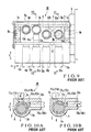
notch 13c constituting the air passage from the exhaust pump is formed smaller than thenotch 13a constituting the air passage from the intake pump, as shown in Figs. 10A and 10B. Inversely, in the suction operation of the suction heads, if the suction time of the suction heads is shorter than the air discharge time of the nozzles, thenotch 13a is formed smaller than thenotch 13c, as shown in Figs. 12A and 12B. - As shown in Fig. 10B, if the
notch 13c is made small to shorten the air discharge time from the nozzles, along with rotation of thevalve body 6, as the opening of thevent hole 11c is enlarged, the opening of thevent hole 12c is narrowed. For this reason, a predetermined air pressure cannot be obtained on the nozzle side. - Accordingly, the amount of air from the nozzles becomes short and air blowing to the stacked sheets is not performed sufficiently, and two or more sheets are undesirably drawn by the suction heads. In this case, operation of the printing press must be stopped, or the printing press may cause a trouble to decrease the productivity. Since the supply amount of reverse air from the suction heads becomes short to delay sheet release from the suction heads, the sheet may be cut or bent to degrade the printing quality.
- When the operation speed of the printing press increases, the time of forming the air passage in the rotary valve is shortened. Then, a predetermined discharge air pressure from the nozzles cannot be obtained, in the same manner as described above.
- Meanwhile, as shown in Fig. 12A, if the
notch 13a is made small to shorten the suction time of the suction heads, along with rotation of thevalve body 6, as the opening of thevent hole 11a is enlarged, the opening of thevent hole 12a is narrowed. As a result, a predetermined air pressure cannot be obtained with the suction heads, and defective sheet supply may occur. - Fig. 11 shows the relationship in pressure of the input/output air of the rotary valve of Fig. 10B during the discharge operation. Referring to Fig. 11, reference numeral b1 denotes the pressure of the exhaust air input to the
rotary valve 30. The pressure b1 is the pressure of the exhaust air from the exhaust pump. Reference numeral b2 denotes the pressure of the discharge air output from the rotary valve. The pressure b2 is the pressure of the discharge air from the nozzles. - When the machine angle of rotation of the printing press becomes β1, the
notch 13c of thevalve body 6 opposes the vent holes 11c and 12c of thesleeve 4, and discharge air is supplied from an exhaust pump 36 to the nozzles through theexhaust air passage 9c, thenotch 13c, and thedischarge air passage 10c. The pressure of air supplied to the nozzles at this time is expressed as a pressure P. Subsequently, when the machine angle of rotation becomes β2, thenotch 13c is displaced from thevent hole 12c, thevent hole 12c is closed with the circumferential surface of thevalve body 6, and supply of the discharge air to thedischarge air passage 10c is stopped. - At this time, in the conventional
rotary valve 30, a pressure b3 of the discharge air between the machine angles β1 and β2 of rotation becomes lower than a necessary pressure b4 by a pressure difference ΔP. This is due to the following reason. Since thenotch 13c is small, along with rotation of thevalve body 6, as the opening of thevent hole 11c is enlarged, the opening of thevent hole 12c is narrowed, so the air exhausted from the exhaust pump 36 is not sufficiently supplied to the nozzles. - Fig. 13 shows the relationship of the input/output air of the rotary valve shown in Fig. 12A during the suction operation. As shown in Fig. 13, even during the suction operation, a pressure loss in air of the rotary valve occurs. Reference numeral a1 denotes the pressure of the intake air input to the
rotary valve 30. The pressure a1 is the pressure of intake air from the intake pump. Reference numeral a2 denotes the pressure of the suction air output from therotary valve 30. The pressure a2 is the pressure of the suction air of the suction heads. As shown in Fig. 13, a pressure a3 of the suction air between the machine angles β1 and β2 of rotation becomes higher than a necessary pressure a4 by a pressure difference ΔP. - Document DE-A-4 215 226 discloses a rotary valve in which the compressed air source and the hollow portion are connected through a hole extending towards a radial direction of valve body and whole of a main body. Therefore, the compressed air sources.in the hollow portion are either disconnected or connected from each other by a rotation the valve body. The opening in the rotary valve according to the mentioned document is in the circumferential surface of the valve body. This means that the opening and air source on the circumferential surface of the valve are intermittently connected to each other, where the intermittence is subjected to the rotation of the valve body. In a structure where the intermittence is subject to the rotation of the valve body, the air flow is interrupted.
- Document US-A-3 884 460 shows a spool valve member in which a chamber is formed along the central axis. Pressurized air supplied into the chamber flows into the outlet channel through the radial bores, so as to provide a blast to the suction cup. Pressurized air is supplied into the chamber in a radial direction, i.e. through the supply channel, the inlet opening and the distribution channel.
-
Document DE-195 15 301 relates to an arrangement for controlling air with an air diffuser comprising a controller cylinder which is pivotably driveable during a cycle, which, with its cylindrical shell surface, is pivotably run on bearings in the bore hole of a control bearing bush which closely surrounds the controller cylinder, whereby the controller cylinder discloses an air admittable inner chamber from which radial control recesses lead to the cylindrical shell surface of the controller cylinder, which, with radial control connections formed in the control socket/liner, can be overlapped. - It is an object of the present invention to provide a rotary valve which can obtain a predetermined air pressure even when the actuation time by the air is short.
- It is another object of the present invention to provide a rotary valve in which a pressure loss in air in its interior is decreased.
- In order to achieve the above objects, according to the present invention, there is provided a rotary valve, which is interposed between a first and a second air source for supplying air, and at least one air unit that performs a predetermined operation upon reception of the air supplied from the first and second air sources, to supply/stop supplying air, comprising a valve body rotatably driven in a cylinder, a main body for rotatably supporting the valve body, notches formed in a circumferential surface of the valve body, to be connected to the first air source, and further comprising a first hollow portion formed in said valve body, and wherein said rotary valve comprises a first air passage formed in said main body and having one end side connected to said first air source and the other end side that opens in an inner circumferential surface of said cylinder, a second air passage formed in said main body and having one end side connected to the first air unit and the other end side that opens in said inner circumferential surface of said cylinder, said first air passage being connected to said second air passage through said notches and a first communication hole formed in said valve body to connect said first hollow portion and said second air passage to each other, characterized in that the first hollow portion is formed in said valve body in an axial direction and having, in one end face of said valve body, an opening through which said first hollow portion is connected to the second air source, and in that the rotary valve further comprises a third air passage formed in said. main body and having one end side connected to the second air unit and the other end side that opens in an inner circumferential surface of said cylinder, a second hollow portion formed in said valve body in an axial direction and connected to said first air source, and a second communication hole formed in said valve body to connect said second hollow portion and said third air passage to each other.
-
- Fig. 1 is a plan view of a rotary valve;
- Fig, 2A is a sectional view taken along the line I - I of Fig. 1, and Fig. 2B is a sectional view taken along the line II - II of Fig. 1;
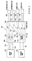
- Fig. 3 is a diagram showing the schematic arrangement of the sheet feeding unit of a printing press to which the embodiment according to Fig. 1 is applied;
- Fig. 4 is a plan view of a rotary valve according to the present invention;
- Fig. 5A is a sectional view taken along the line III - III of Fig. 4, and Fig. 5B is a sectional view taken along the line IV - IV of Fig. 4;
- Fig. 6 is a diagram showing the schematic arrangement of a sheet feeding unit to which the embodiment according to the invention is applied;
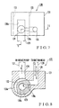
- Fig. 7 is a plan view of another rotary valve; Fig. 8 is a sectional view taken along the line V - V of Fig. 7;
- Fig. 9 is a plan view of a conventional rotary valve;
- Fig. 10A is a sectional view taken along the line VI - VI of Fig. 9, and Fig. 10B is a sectional view taken along the line VII - VII of Fig. 9;
- Fig. 11 is a graph showing the relationship in pressure of the input/output air of the rotary valve of Fig. 10B during discharge operation;
- Fig. 12A is a sectional view showing the main part of another example of the rotary valve that corresponds to Fig. 10A, and Fig. 12B is a sectional view showing the main part of still another example of the rotary valve that corresponds to Fig. 10B; and
- Fig. 13 is a graph showing the relationship in pressure of the input/output air of the rotary valve of Fig. 12A during suction operation.
-
- The present invention will be described in detail with reference to the accompanying drawings.
- Fig. 3 shows the schematic arrangement of a sheet feeding unit for a printing press. Referring to Fig. 3, the air source side of a
rotary valve 101 is connected to anintake pump 134 serving as an intake air source, and anexhaust pump 136 serving as an exhaust air source, throughhoses hose 119, respectively. The suction/discharging side of therotary valve 101 is connected to suctionheads nozzles hoses hoses nozzles - Fig. 1 shows the rotary valve shown in Fig. 3. Referring to Fig. 1, a
main body 102 formed into a substantially rectangular parallelepiped shape is fixed to aframe 105 of the sheet feeding unit through a bracket 105a. As shown in Figs. 2A and 2B, the lower portion of themain body 102 in one end side in the direction of an arrow Y swells in an arcuated manner to constitute a swellingportion 102a. - A through
hole 103 extending in the direction of an arrow X is formed in the swellingportion 102a, and acylindrical sleeve 104 is fixed to the inner surface of the throughhole 103. Avalve body 106 is engaged in thesleeve 104.End shafts valve body 106 are rotatably supported by thesleeve 104 throughbearings valve body 106 rotates in an interlocked manner with rotation of the printing press through oneend shaft 106a. - Two
air passages hole 103, are formed in the upper portion side of themain body 102 corresponding to the swellingportion 102a, to extend in the vertical direction (the direction of an arrow Z). As described above, theair passages intake pump 134 through thehoses air passages -
Air passages main body 102 to extend in the direction of the arrow Y perpendicularly to theintake air passages air passages air passages air passages 110a to 110d opens to the outside of themain body 102 while the other end thereof is connected to the throughhole 103. - Of the
air passages 110a to 110d, theair passages hoses air passages air passages nozzles hoses air passages -
Vent holes sleeve 104 to respectively correspond to theintake air passages Vent holes sleeve 104 to respectively correspond to thesuction air passages discharge air passages - As shown in Figs. 2A and 2B, a blind hole-like
hollow portion 114 is formed in thevalve body 106 to have an opening in the end face of thevalve body 106 on oneend shaft 106b side and to extend in the direction of an arrow X to a position corresponding to theintake air passage 109a. As described above, theexhaust pump 136 is connected to the opening side of thehollow portion 114 through thehose 119. Accordingly, thehollow portion 114 constitutes an exhaust air passage (air passage for the exhaust air source). - A
communication hole 115a (Fig. 2A) is formed in thevalve body 106. Thecommunication hole 115a allows thehollow portion 114 to communicate with thesuction air passage 110a through thevent hole 112a. Similarly, acommunication hole 115b is formed in thevalve body 106 at a position displaced from thecommunication hole 115a in the axial direction and to be phase-shifted from thecommunication hole 115a in the rotating direction. Thecommunication hole 115b allows thehollow portion 114 to communicate with thesuction air passage 110b through thevent hole 112b. - A
communication hole 115c (Fig. 2B) is formed in thevalve body 106. Thecommunication hole 115c allows thehollow portion 114 to communicate with thedischarge air passage 110c through thevent hole 112c. Similarly, acommunication hole 115d is formed in thevalve body 106 at a position displaced from thecommunication hole 115c in the axial direction and to be phase-shifted from thecommunication hole 115c in the rotating direction. Thecommunication hole 115d allows thehollow portion 114 to communicate with thedischarge air passage 110d through thevent hole 112d. - As shown in Fig. 2A, a
notch 113a through which thevent holes valve body 106 corresponding to theintake air passage 109a and thesuction air passage 110a. Similarly, anotch 113b through which the vent holes 111b and 112b communicate with each other is formed in the circumferential surface of thevalve body 106 corresponding to theintake air passage 109b and thesuction air passage 110b, at a position displaced from thenotch 113a in the axial direction and to be phase-shifted from thenotch 113a in the rotating direction of thevalve body 106. - Therefore, the characteristic feature of this embodiment resides in that the blind hole-like
hollow portion 114 having a circular section is formed in thevalve body 106 to extend in the axial direction and that thishollow portion 114 serves as the exhaust air passage. The conventionalexhaust air passages hollow portion 114, so that the reverse air passage 31 and thenotches valve body 6 become unnecessary. - The switching operation between intake and exhaustion done by the rotary valve having this arrangement will be described with reference to Fig. 3.
- When the
valve body 106 is rotated in an interlocked manner with rotation of the printing press, thecommunication hole 115d of thevalve body 106 opposes thevent hole 112d of thesleeve 104, and thehollow portion 114 serving as the exhaust air passage and thedischarge air passage 110d communicate with each other through thecommunication hole 115d and thevent hole 112d. Therefore, exhaust air from theexhaust pump 136 flows through thehollow portion 114 and theair passage 110d, and is discharged from thenozzle 137b to blow the air to the sheets (step S11). - When the
valve body 106 is continuously rotated, thenotch 113a opposes thevent holes intake air passage 109a and thesuction air passage 110a communicate with each other through thenotch 113a. Thus, as shown in Fig. 2A, intake air A from theintake pump 134 flows through theair passages suction head 135a serving as the first sucker, to draw a sheet by suction (step S12). - When the
valve body 106 is continuously rotated, thecommunication hole 115c opposes thevent hole 112c of thesleeve 104, and thehollow portion 114 serving as the exhaust air passage and thedischarge air passage 110c communicate with each other through thecommunication hole 115c and a vent hole 111c, as shown in Fig. 2B. Exhaust air B from theexhaust pump 134 is supplied to thenozzle 137a, serving as the leveling foot, through thehollow portion 114 and theair passage 110c. The air is blown to a portion between the highest sheet and the second sheet, to separate them from each other (step S13). - When the
valve body 106 is continuously rotated, thenotch 113b opposes the vent holes 112b and 111b, and theintake air passage 109b and thesuction air passage 110b communicate with each other through thenotch 113b. Therefore, intake air from theintake pump 134 is supplied to thesuction head 135b, serving as the second sucker, through theair passages - Simultaneously, the
communication hole 115a of thevalve body 106 opposes thevent hole 112a, and thehollow portion 114 and thesuction air passage 110a communicate with each other through thecommunication hole 115a and thevent hole 112a. The exhaust air from theexhaust pump 136 is supplied to thesuction head 135a, serving as the first sucker, through thehollow portion 114 and theair passage 110a. The sheet is quickly released from thesuction head 135a that has ended the suction operation (step S15). As a result, a sheet which is conveyed to above the feeder board while being drawn by thesuction head 135b, serving as the second sucker will not be cut or bent. - When the
suction head 135b during sheet conveyance is located above the feeder board, as thevalve body 106 is rotated, thecommunication hole 115b opposes thevent hole 112b, and thehollow portion 114 and thesuction air passage 110b communicate with each other through thecommunication hole 115b and venthole 112b. The exhaust air from theexhaust pump 136 is supplied to thesuction head 135b through thehollow portion 114 and theair passage 110b. The sheet is quickly released from thesuction head 135b, and is supplied onto the feeder board (step S16). - According to this embodiment, during the air discharge operation, the air is supplied from the
exhaust pump 136 to thenozzles hollow portion 114 and the communication holes 115c and 115d. Therefore, the air blowing and leveling foot operation can be reliably performed within a short period of time with sufficiently high-pressurized air. - During the air discharge operation, the
hollow portion 114, the communication holes 115c and 115d, the vent holes 111c and 111d, and thedischarge air passages - Since the exhaust air is supplied through the
hollow portion 114 of thevalve body 106 which has a large sectional area, the pressure loss of the air at the valve portion is decreased. Also, theexhaust air passages sleeve 4 become unnecessary, and only thehollow portion 114 and thecommunication holes 115a to 115d need be formed in thevalve body 106. Therefore, the structure is simplified and machining becomes easy. - Since the
notches valve body 6 and the reverse air passage 31, which are conventionally necessary, becomes unnecessary, the structure is.simplified. Since thehollow portion 114, thecommunication holes vent holes suction air passages - Fig. 4 shows a rotary valve according to the first embodiment of the present invention. Fig. 5A shows a section taken along the line III- III of Fig. 4, and Fig. 5B shows section taken along'the line IV - IV of Fig. 4. In Fig. 4 and Figs. 5A and 5B, portions that are identical to those of Fig. 1 and Figs. 2A and 2B are denoted by the same reference numerals as in Fig. 1 and Figs. 2A and 2B, and a detailed description thereof will be omitted.
- The first embodiment is different from the embodiment shown in Fig 1 in that, as shown in Fig. 4, a
partition wall 114c is formed at the center of ahollow portion 114 to divide thehollow portion 114 into a firsthollow portion 114a and a secondhollow portion 114b. - As shown in Fig. 6, the first
hollow portion 114a is connected to anintake pump 134 through ahose 119a to constitute an intake air passage. The secondhollow portion 114b is connected to anexhaust pump 136 through ahose 119b, in the same manner as in the first embodiment.Air passages main body 102 are connected to theexhaust pump 136 throughhoses - A
communication hole 215a (Fig. 5A), where thehollow portion 114 extends to communicate with asuction air passage 110a through avent hole 112a, is formed in thevalve body 106. Similarly, acommunication hole 215b, where thehollow portion 114 extends to communicate with thesuction air passage 110b through avent hole 112b, is formed in thevalve body 106, at a position displaced from thecommunication hole 215a in the axial direction and to be phase-shifted from thecommunication hole 215a in the rotating direction. Acommunication hole 215c (Fig. 5B), where thehollow portion 114 extends to communicate with adischarge air passage 110c through avent hole 112c, is also formed in thevalve body 106. Similarly, acommunication hole 215d, where thehollow portion 114 extends to communicate with asuction air passage 110d through avent hole 112d, is formed in thevalve body 106, at a position displaced from thecommunication hole 215c in the axial direction and to be phase-shifted from thecommunication hole 215c in the rotating direction. - The switching operation between intake and exhaustion done by the rotary valve having this arrangement will be described with reference to Fig. 6.
- When the
valve body 106 is rotated in an interlocked manner with rotation of the printing press, thecommunication hole 215d of thevalve body 106 opposes thevent hole 112d of thesleeve 104, and the secondhollow portion 114b serving as the exhaust air passage and thedischarge air passage 110d communicate with each other through acommunication hole 115d and thevent hole 112d. Exhaust air from theexhaust pump 136 is supplied to anozzle 137b through the secondhollow portion 114b and theair passage 110d, to blow air to the sheets (step S21). - When the
valve body 106 is continuously rotated, itscommunication hole 215a opposes thevent hole 112a, and the firsthollow portion 114a serving as the intake air passage and thesuction air passage 110a communicate with each other through thecommunication hole 215a and thevent hole 112a. Intake air from theintake pump 134 is supplied to asuction head 135a, serving as the first sucker, through thesuction air passage 110a and the firsthollow portion 114a, to draw a sheet by suction (step S22). - When the
valve body 106 is continuously rotated, thecommunication hole 215c opposes thevent hole 112c of asleeve 104, and the secondhollow portion 114b serving as the exhaust air passage and thedischarge air passage 110c communicate with each other through thecommunication hole 215c and thevent hole 112c, as shown in Fig. 5B. Exhaust air B from theexhaust pump 136 is supplied to anozzle 137a, serving as the leveling foot, through the secondhollow portion 114b and thesuction air passage 110c. The air is blown to a portion between the highest sheet and the second sheet, to separate them from each other (step S23). - When the
valve body 106 is continuously rotated, thecommunication hole 215b of thevalve body 106 opposes thevent hole 112b, and the firsthollow portion 114a and thesuction air passage 110a communicate with each other through thecommunication hole 215b and thevent hole 112b. Intake air from theintake pump 134 is supplied to asuction head 135b, serving as the second sucker, through the firsthollow portion 114a and thesuction air passage 110a, to draw a sheet by suction (step S24). - Simultaneously, a
notch 113a opposes thevent hole 112a and avent hole 111a, and anexhaust air passage 116a and thedischarge air passage 110a communicate with each other through thenotch 113a, as shown in Fig. 5A. Thus, the exhaust air B from theexhaust pump 136 is supplied to thesuction head 135a, serving as the first sucker, through theair passages suction head 135a that has ended the suction operation (step S25). As a result, a sheet which is conveyed to above the feeder board while being drawn by thesuction head 135b, serving as the second sucker, will not be cut or bent. - When the
second suction head 135b during sheet conveyance is located above the feeder board, as thevalve body 106 is rotated, anotch 113b opposes thevent hole 112b and avent hole 111b, and anexhaust air passage 116b and thedischarge air passage 110b communicate with each other through thenotch 113b. The exhaust air from theexhaust pump 136 is supplied to thesuction head 135b through theair passages suction head 135b, and is supplied to above the feeder board (step S26). - According to this embodiment, during the suction operation, the air is supplied from the
intake pump 134 to the suction heads 135a and 135b through the firsthollow portion 114a and thecommunication holes - During the suction operation, the first
hollow portion 114a, thecommunication holes vent holes hollow portion 114a of thevalve body 106, which has a large sectional area, serves as the intake air passage, the pressure loss of the air at the valve portion is small. - Fig. 7 shows another rotary valve, and Fig. 8 shows a section taken along the line V - V of Fig. 7.
- A
rotary valve 120 of the embodiment according to Fig. 7 controls to supply/stop supplying of the air of the first sucker of the sheet feeding unit. More specifically, a throughhole 122 is formed in amain body 121 of therotary valve 120. Avalve body 123 which rotates in an interlocked manner with the printing press is rotatably engaged with the inner surface of the throughhole 122. Anintake air passage 124 and asuction air passage 125 are formed in the upper portion of themain body 121. Theair passage 124 has an open upper end and a lower end that communicates with the throughhole 122. Thesuction air passage 125 has an L-shaped section. - The upper end open side of the
intake air passage 124 is connected to an intake pump through ahose 127. The upper end open side of thesuction air passage 125 is connected to a suction head, serving as the first sucker, through ahose 128. Anotch 126a is formed in part of the circumferential surface of thevalve body 123. A blind hole-likehollow portion 126b is formed in thevalve body 123 to extend in the axial direction. Acommunication hole 126c, through which thehollow portion 126b and thesuction air passage 125 communicate with each other, is also formed in thevalve body 123. The open end side of thehollow portion 126b is connected to an exhaust pump through ahose 129. Thehollow portion 126b constitutes an exhaust air passage. - In this arrangement, when the
valve body 123 is rotated in an interlocked manner with the printing press, thenotch 126a opposes theintake air passage 124 and thesuction air passage 125, and the twoair passages notch 126a. Intake air A is supplied to a suction head, serving as the first sucker, through theair passages - When the
valve body 123 is continuously rotated, air intake is controlled by another rotary valve (not shown), and a sheet is drawn by suction with a suction head serving as the second sucker. - Simultaneously, the
communication hole 126c of thevalve body 123 opposes thesuction air passage 125, and thehollow portion 126b and thesuction air passage 125 communicate with each other. Exhaust air B from the exhaust pump is supplied to the suction head, serving as the first sucker, through thesuction air passage 125, and a.sheet is quickly released from the suction head that has ended the suction operation. As a result, a sheet which is drawn by the suction head, serving as the second sucker, and is conveyed to above the feeder board will not be cut or bent. - According to this embodiment, during the reverse operation, a sufficient amount of air can be supplied to the suction heads through the
hollow portion 126b and thecommunication hole 126c within a short period of time. Since thehollow portion 126b, thecommunication hole 126c, and thesuction air passage 125 are located in a substantially straight line and the distance between thehollow portion 126b and thesuction air passage 125 reaches a minimum, the air pressure loss in the air passage is decreased. - In this embodiment, when the intake air operation time is short, an exhaust pump 137 may be connected through the
hose 127 so that theair passage 124 serves as the exhaust air passage, and anintake pump 134 may be connected to the open end side of thehollow portion 126b through thehose 129 so that thehollow portion 126b serves as the intake air passage. - In the embodiments according to Figs. 1 and 4, the
sleeve 104 formed with thevent holes valve body 123 may be directly engaged in the throughhole 122 of themain body 121, as in the third embodiment. With this structure, thevent holes 111a to 111d become unnecessary. Specifically, it suffices if the valve body is rotatably held in a cylinder including a sleeve formed in the main body. - In the above embodiments, the rotary valve is applied to the sheet feeding unit. However, the present invention is not limited to this, but can similarly be applied to, e.g., the convertible cylinder unit or a sheet discharge unit of a printing press main body. Although the hollow portion is formed to have a circular section, it can have various other sections, e.g., an elliptical section, a square section, or a triangular section. Although only one rotary valve is used in the above embodiments, a series of a plurality of rotary valves may be used.
- As has been described above, according to the present invention, the valve body of the rotary valve has a hollow portion and a notched portion respectively connected to different air sources, and the hollow portions and notched portions are combined with air passages that require predetermined characteristics. If the hollow portion is used as an air passage having a short air operation time and the notched portion is used as an air passage having a long air operation time, predetermined air pressures required for the respective air passages can be obtained.
- Since the hollow portion and the notched portion are formed in the valve body, the entire rotary valve can be made compact. The reverse air passage from the suction unit can also be constituted by a hollow portion or a notch formed in the valve body, thus decreasing the manufacturing cost.
Claims (7)
- A rotary valve, which is interposed between a first air source (136) and a second air source (134) for supplying air, and at least one air unit (135a, 135b, 137a, 137b) that performs a predetermined operation upon reception of the air supplied from said first and second air sources (136, 134), to supply/stop supplying air, comprising:a valve body (106) rotatably driven in a cylinder;a main body (102) for rotatably supporting said valve body (106); andnotches (113a, 113b) formed in a circumferential surface of said valve body (106) to be connected to the first air source (136), and further comprising a first hollow portion (114a) formed in said valve body (106), and wherein said rotary valve comprisesa first air passage (116a, 116b) formed in said main body (102) and having one end side connected to said first air source (136) and the other end side that opens in an inner circumferential surface of said cylinder,a second air passage (110a, 110b) formed in said main body (102) and having one end side connected to the first air unit (135a, 135b) and the other end side that opens in said inner circumferential surface of said cylinder, said first air passage (116a, 116b) being connected to said second air passage (110a, 110b) through said notches (113a, 113b), anda first communication hole (215a, 215b) formed in said valve body (106) to connect said first hollow portion (114a) and said second air passage (110a, 110b) to each other, characterized in that the first hollow portion (114a) is formed in said valve body (106) in an axial direction and having, in one end face of said valve body (106), an opening through which said first hollow portion (114a) is connected to the second air source (134), and in that the rotary valve further comprisesa third air passage (110c, 110d) formed in said main body (102) and having one end side connected to the second air unit (137a, 137b) and the other end side that opens in an inner circumferential surface of said cylinder,a second hollow portion (114b) formed in said valve body (106) in an axial direction and connected to said first air source (136), anda second communication hole (215c, 215d) formed in said valve body (106) to connect said second hollow portion (114b) and said third air passage (110c, 110d) to each other.
- A rotary valve according to claim 1, wherein one of said first and second air sources comprises an intake pump for suppyling intake air, and the other one of said first and second air sources comprises an exhaust pump for supplying exhaust air.
- A rotary valve according to claim 2, wherein said one end side of said first air passage is connected to said exhaust pump, said one end side of said second air passage is connected to said suction unit, said first hollow portion is connected to said intake pump, and said suction unit is connected to said exhaust pump through said second air passage, said notch, and said first air passage, and to said intake pump through said second air passage, said first communication hole, and said first hollow portion.
- A rotary valve according to claim 1, wherein one of said first and second air sources comprises an intake pump for supplying intake air, the other one of said first and second air sources comprises an exhaust pump for supplying exhaust air, one of said first and second air units comprises a suction unit which performs suction operation upon receiving the intake air from said intake pump, and the other one of said first and second air units comprises a discharge unit which performs discharge operation upon receiving the exhaust air from said exhaust pump.
- A rotary valve according to claim 4, wherein said first and second communication holes are arranged to be displaced from each other in an axial direction of said cylinder, said first communication hole is arranged at the same position as an opening of said second air passage in the axial direction of said cylinder, and said second communication hole is arranged at the same position as an opening of said third air passage in the axial direction of said cylinder.
- A rotary valve according to claim 1, wherein openings of said first and third air passages are arranged to be displaced from each other in an axial direction of said cylinder.
- A rotary valve according to claim 1, wherein openings of said first and second air passages are arranged at the same position in an axial direction of said cylinder and to be phase-shifted from each other in a rotational direction of said valve body.
Applications Claiming Priority (6)
| Application Number | Priority Date | Filing Date | Title |
|---|---|---|---|
| JP17054297 | 1997-06-26 | ||
| JP170542/97 | 1997-06-26 | ||
| JP17054297 | 1997-06-26 | ||
| JP2714298A JPH1172168A (en) | 1997-06-26 | 1998-02-09 | Rotary valve |
| JP2714298 | 1998-02-09 | ||
| JP27142/98 | 1998-02-09 |
Publications (4)
| Publication Number | Publication Date |
|---|---|
| EP0890433A2 EP0890433A2 (en) | 1999-01-13 |
| EP0890433A3 EP0890433A3 (en) | 1999-04-28 |
| EP0890433B1 true EP0890433B1 (en) | 2003-04-16 |
| EP0890433B9 EP0890433B9 (en) | 2003-10-29 |
Family
ID=26365037
Family Applications (1)
| Application Number | Title | Priority Date | Filing Date |
|---|---|---|---|
| EP19980250235 Expired - Lifetime EP0890433B9 (en) | 1997-06-26 | 1998-06-25 | Rotary valve in a sheet feeding unit of an offset printing press |
Country Status (5)
| Country | Link |
|---|---|
| US (1) | US6254082B1 (en) |
| EP (1) | EP0890433B9 (en) |
| JP (1) | JPH1172168A (en) |
| DE (1) | DE69813393T2 (en) |
| ES (1) | ES2196484T3 (en) |
Families Citing this family (4)
| Publication number | Priority date | Publication date | Assignee | Title |
|---|---|---|---|---|
| US6976464B2 (en) * | 2003-05-28 | 2005-12-20 | Dragon America Motor Technologies, Inc. | Semi-rotating valve assembly for use with an internal combustion engine |
| JP4336223B2 (en) * | 2004-02-24 | 2009-09-30 | 株式会社リコー | Pneumatic paper feeder and electrophotographic apparatus having the same |
| JP5658868B2 (en) * | 2009-02-19 | 2015-01-28 | 株式会社東芝 | Paper sheet take-out device |
| US8939445B2 (en) * | 2013-05-30 | 2015-01-27 | Kimberly-Clark Worldwide, Inc. | Vacuum roll with internal rotary valve |
Family Cites Families (13)
| Publication number | Priority date | Publication date | Assignee | Title |
|---|---|---|---|---|
| DE199488C (en) | 1905-05-24 | |||
| US1207769A (en) * | 1914-10-10 | 1916-12-12 | Under Feed Stoker Company Of America | Valve for automatic stoker-controllers. |
| US1677499A (en) * | 1927-11-19 | 1928-07-17 | William J Smith | Rotary valve |
| CH199488A (en) * | 1936-09-23 | 1938-08-31 | Georg Dr Ing E H Spiess | Rotary slide control device for pneumatic sheet feeders. |
| US3069025A (en) | 1959-07-01 | 1962-12-18 | Berkley Machine Co | Rotary valve for controlling application of suction |
| DE1786165A1 (en) | 1968-08-26 | 1972-01-20 | Harris Intertype Corp | Control for a sheet feeder |
| CS155031B1 (en) * | 1972-05-26 | 1974-04-30 | ||
| USRE31529E (en) * | 1979-02-16 | 1984-03-06 | Ball Corporation | Electronic valve assembly for glassware forming machinery |
| CH639623A5 (en) * | 1979-06-23 | 1983-11-30 | Winkler Duennebier Kg Masch | DEVICE FOR TRANSPORTING AREA PARTS, ESPECIALLY PAPER SHEETS, CARDS, MAIL OR SHIPPING PAPERS. |
| JP2505327B2 (en) | 1991-07-16 | 1996-06-05 | セントラル硝子株式会社 | Laminated material containing soft fluororesin |
| DE4215226C2 (en) | 1992-05-09 | 1995-09-07 | Kba Planeta Ag | Rotary slide valve for controlling suction and blast air consumers |
| DE4315549C2 (en) | 1993-05-10 | 2003-11-20 | Heidelberger Druckmasch Ag | Device for suction air control for a sheet transfer drum |
| DE19515301C2 (en) | 1995-04-26 | 1998-07-30 | Roland Man Druckmasch | Air control arrangement |
-
1998
- 1998-02-09 JP JP2714298A patent/JPH1172168A/en active Pending
- 1998-06-24 US US09/104,024 patent/US6254082B1/en not_active Expired - Fee Related
- 1998-06-25 ES ES98250235T patent/ES2196484T3/en not_active Expired - Lifetime
- 1998-06-25 DE DE1998613393 patent/DE69813393T2/en not_active Expired - Fee Related
- 1998-06-25 EP EP19980250235 patent/EP0890433B9/en not_active Expired - Lifetime
Also Published As
| Publication number | Publication date |
|---|---|
| US6254082B1 (en) | 2001-07-03 |
| DE69813393T2 (en) | 2004-02-19 |
| EP0890433A2 (en) | 1999-01-13 |
| EP0890433B9 (en) | 2003-10-29 |
| JPH1172168A (en) | 1999-03-16 |
| ES2196484T3 (en) | 2003-12-16 |
| EP0890433A3 (en) | 1999-04-28 |
| DE69813393D1 (en) | 2003-05-22 |
Similar Documents
| Publication | Publication Date | Title |
|---|---|---|
| US7207265B2 (en) | Devices for turning sheets in a sheet-fed rotary printing machine | |
| EP0890433B9 (en) | Rotary valve in a sheet feeding unit of an offset printing press | |
| JP4344035B2 (en) | Equipment for applying liquid to printed sheets with a sheet-fed rotary printing press | |
| JPH11334035A (en) | Sheet feeder for sheet fed printer and printer provided with the same | |
| KR20100098618A (en) | Device for variably adjusting the control times of gas exchange valves of an internal combustion engine | |
| KR20150086296A (en) | Suction roll system | |
| JP4252642B2 (en) | Rotary valve | |
| US20230184340A1 (en) | Automatic drain valve for condensed water | |
| JPH09138629A (en) | Air manifold system | |
| CN118255105A (en) | Material conveying device | |
| US7631599B2 (en) | Sheet guide apparatus | |
| US7497431B2 (en) | Pneumatic type paper feeding apparatus | |
| JPH1172169A5 (en) | ||
| JP4413467B2 (en) | A sheet guide cylinder having a sheet holding mechanism capable of controlling air pressure | |
| JPS6344661B2 (en) | ||
| CN106414076B (en) | Wetting device for printing press and printing press having the same | |
| JP3341882B2 (en) | Inkjet printer | |
| JPH04101001A (en) | Scroll type fluid machine | |
| JPS60157431A (en) | Adjusting device for sheet feeder | |
| US5240237A (en) | Air flow path switching device for printing apparatus | |
| JPH0312514Y2 (en) | ||
| JPH1059567A (en) | Paper supply device of paper printing machine | |
| JPH0716098Y2 (en) | Hydrostatic bearing device | |
| US2884059A (en) | Suction roll nozzle with manifold and valve means | |
| JPH07229484A (en) | Scroll compressor |
Legal Events
| Date | Code | Title | Description |
|---|---|---|---|
| PUAI | Public reference made under article 153(3) epc to a published international application that has entered the european phase |
Free format text: ORIGINAL CODE: 0009012 |
|
| 17P | Request for examination filed |
Effective date: 19980723 |
|
| AK | Designated contracting states |
Kind code of ref document: A2 Designated state(s): CH DE ES FR GB IT LI NL SE |
|
| AX | Request for extension of the european patent |
Free format text: AL;LT;LV;MK;RO;SI |
|
| PUAL | Search report despatched |
Free format text: ORIGINAL CODE: 0009013 |
|
| AK | Designated contracting states |
Kind code of ref document: A3 Designated state(s): AT BE CH CY DE DK ES FI FR GB GR IE IT LI LU MC NL PT SE |
|
| AX | Request for extension of the european patent |
Free format text: AL;LT;LV;MK;RO;SI |
|
| AKX | Designation fees paid |
Free format text: CH DE ES FR GB IT LI NL SE |
|
| 17Q | First examination report despatched |
Effective date: 20000413 |
|
| GRAH | Despatch of communication of intention to grant a patent |
Free format text: ORIGINAL CODE: EPIDOS IGRA |
|
| RIC1 | Information provided on ipc code assigned before grant |
Free format text: 7B 41F 21/00 A, 7B 65H 3/08 B, 7B 65H 3/14 B, 7B 65H 3/48 B, 7F 16K 5/04 B |
|
| GRAH | Despatch of communication of intention to grant a patent |
Free format text: ORIGINAL CODE: EPIDOS IGRA |
|
| GRAA | (expected) grant |
Free format text: ORIGINAL CODE: 0009210 |
|
| AK | Designated contracting states |
Designated state(s): CH DE ES FR GB IT LI NL SE |
|
| REG | Reference to a national code |
Ref country code: GB Ref legal event code: FG4D |
|
| REG | Reference to a national code |
Ref country code: SE Ref legal event code: TRGR |
|
| REG | Reference to a national code |
Ref country code: CH Ref legal event code: EP |
|
| REF | Corresponds to: |
Ref document number: 69813393 Country of ref document: DE Date of ref document: 20030522 Kind code of ref document: P |
|
| REG | Reference to a national code |
Ref country code: CH Ref legal event code: NV Representative=s name: LUCHS & PARTNER PATENTANWAELTE |
|
| ET | Fr: translation filed | ||
| REG | Reference to a national code |
Ref country code: ES Ref legal event code: FG2A Ref document number: 2196484 Country of ref document: ES Kind code of ref document: T3 |
|
| PLBE | No opposition filed within time limit |
Free format text: ORIGINAL CODE: 0009261 |
|
| STAA | Information on the status of an ep patent application or granted ep patent |
Free format text: STATUS: NO OPPOSITION FILED WITHIN TIME LIMIT |
|
| NLR4 | Nl: receipt of corrected translation in the netherlands language at the initiative of the proprietor of the patent | ||
| 26N | No opposition filed |
Effective date: 20040119 |
|
| ET1 | Fr: translation filed ** revision of the translation of the patent or the claims | ||
| PGFP | Annual fee paid to national office [announced via postgrant information from national office to epo] |
Ref country code: NL Payment date: 20090615 Year of fee payment: 12 |
|
| PGFP | Annual fee paid to national office [announced via postgrant information from national office to epo] |
Ref country code: SE Payment date: 20090605 Year of fee payment: 12 Ref country code: IT Payment date: 20090619 Year of fee payment: 12 |
|
| PGFP | Annual fee paid to national office [announced via postgrant information from national office to epo] |
Ref country code: ES Payment date: 20090710 Year of fee payment: 12 Ref country code: CH Payment date: 20090615 Year of fee payment: 12 |
|
| PGFP | Annual fee paid to national office [announced via postgrant information from national office to epo] |
Ref country code: GB Payment date: 20090624 Year of fee payment: 12 Ref country code: DE Payment date: 20090619 Year of fee payment: 12 |
|
| REG | Reference to a national code |
Ref country code: NL Ref legal event code: V1 Effective date: 20110101 |
|
| REG | Reference to a national code |
Ref country code: CH Ref legal event code: PL |
|
| EUG | Se: european patent has lapsed | ||
| GBPC | Gb: european patent ceased through non-payment of renewal fee |
Effective date: 20100625 |
|
| REG | Reference to a national code |
Ref country code: FR Ref legal event code: ST Effective date: 20110228 |
|
| PG25 | Lapsed in a contracting state [announced via postgrant information from national office to epo] |
Ref country code: IT Free format text: LAPSE BECAUSE OF NON-PAYMENT OF DUE FEES Effective date: 20100625 |
|
| PG25 | Lapsed in a contracting state [announced via postgrant information from national office to epo] |
Ref country code: CH Free format text: LAPSE BECAUSE OF NON-PAYMENT OF DUE FEES Effective date: 20100630 Ref country code: DE Free format text: LAPSE BECAUSE OF NON-PAYMENT OF DUE FEES Effective date: 20110101 Ref country code: LI Free format text: LAPSE BECAUSE OF NON-PAYMENT OF DUE FEES Effective date: 20100630 |
|
| PG25 | Lapsed in a contracting state [announced via postgrant information from national office to epo] |
Ref country code: NL Free format text: LAPSE BECAUSE OF NON-PAYMENT OF DUE FEES Effective date: 20110101 Ref country code: FR Free format text: LAPSE BECAUSE OF NON-PAYMENT OF DUE FEES Effective date: 20100630 |
|
| REG | Reference to a national code |
Ref country code: ES Ref legal event code: FD2A Effective date: 20110718 |
|
| PG25 | Lapsed in a contracting state [announced via postgrant information from national office to epo] |
Ref country code: ES Free format text: LAPSE BECAUSE OF NON-PAYMENT OF DUE FEES Effective date: 20110706 Ref country code: GB Free format text: LAPSE BECAUSE OF NON-PAYMENT OF DUE FEES Effective date: 20100625 |
|
| PG25 | Lapsed in a contracting state [announced via postgrant information from national office to epo] |
Ref country code: ES Free format text: LAPSE BECAUSE OF NON-PAYMENT OF DUE FEES Effective date: 20100626 |
|
| PG25 | Lapsed in a contracting state [announced via postgrant information from national office to epo] |
Ref country code: SE Free format text: LAPSE BECAUSE OF NON-PAYMENT OF DUE FEES Effective date: 20100626 |
|
| PGFP | Annual fee paid to national office [announced via postgrant information from national office to epo] |
Ref country code: FR Payment date: 20090611 Year of fee payment: 12 |