EP0890419A2 - Anschlagsystem und dieses festhaltende Backenplatte - Google Patents
Anschlagsystem und dieses festhaltende Backenplatte Download PDFInfo
- Publication number
- EP0890419A2 EP0890419A2 EP98112659A EP98112659A EP0890419A2 EP 0890419 A2 EP0890419 A2 EP 0890419A2 EP 98112659 A EP98112659 A EP 98112659A EP 98112659 A EP98112659 A EP 98112659A EP 0890419 A2 EP0890419 A2 EP 0890419A2
- Authority
- EP
- European Patent Office
- Prior art keywords
- jaw
- groove
- jaw plate
- work stop
- lock portion
- Prior art date
- Legal status (The legal status is an assumption and is not a legal conclusion. Google has not performed a legal analysis and makes no representation as to the accuracy of the status listed.)
- Ceased
Links
- 230000013011 mating Effects 0.000 claims description 3
- 230000002093 peripheral effect Effects 0.000 claims 1
- 230000007246 mechanism Effects 0.000 description 2
- 230000001154 acute effect Effects 0.000 description 1
- 238000003754 machining Methods 0.000 description 1
Images


Classifications
-
- B—PERFORMING OPERATIONS; TRANSPORTING
- B25—HAND TOOLS; PORTABLE POWER-DRIVEN TOOLS; MANIPULATORS
- B25B—TOOLS OR BENCH DEVICES NOT OTHERWISE PROVIDED FOR, FOR FASTENING, CONNECTING, DISENGAGING OR HOLDING
- B25B1/00—Vices
- B25B1/24—Details, e.g. jaws of special shape, slideways
- B25B1/2405—Construction of the jaws
-
- B—PERFORMING OPERATIONS; TRANSPORTING
- B23—MACHINE TOOLS; METAL-WORKING NOT OTHERWISE PROVIDED FOR
- B23Q—DETAILS, COMPONENTS, OR ACCESSORIES FOR MACHINE TOOLS, e.g. ARRANGEMENTS FOR COPYING OR CONTROLLING; MACHINE TOOLS IN GENERAL CHARACTERISED BY THE CONSTRUCTION OF PARTICULAR DETAILS OR COMPONENTS; COMBINATIONS OR ASSOCIATIONS OF METAL-WORKING MACHINES, NOT DIRECTED TO A PARTICULAR RESULT
- B23Q3/00—Devices holding, supporting, or positioning work or tools, of a kind normally removable from the machine
- B23Q3/02—Devices holding, supporting, or positioning work or tools, of a kind normally removable from the machine for mounting on a work-table, tool-slide, or analogous part
- B23Q3/10—Auxiliary devices, e.g. bolsters, extension members
- B23Q3/102—Auxiliary devices, e.g. bolsters, extension members for fixing elements in slots
-
- B—PERFORMING OPERATIONS; TRANSPORTING
- B25—HAND TOOLS; PORTABLE POWER-DRIVEN TOOLS; MANIPULATORS
- B25B—TOOLS OR BENCH DEVICES NOT OTHERWISE PROVIDED FOR, FOR FASTENING, CONNECTING, DISENGAGING OR HOLDING
- B25B1/00—Vices
- B25B1/24—Details, e.g. jaws of special shape, slideways
- B25B1/2405—Construction of the jaws
- B25B1/2452—Construction of the jaws with supplementary jaws
-
- B—PERFORMING OPERATIONS; TRANSPORTING
- B25—HAND TOOLS; PORTABLE POWER-DRIVEN TOOLS; MANIPULATORS
- B25B—TOOLS OR BENCH DEVICES NOT OTHERWISE PROVIDED FOR, FOR FASTENING, CONNECTING, DISENGAGING OR HOLDING
- B25B1/00—Vices
- B25B1/24—Details, e.g. jaws of special shape, slideways
- B25B1/2405—Construction of the jaws
- B25B1/2478—Construction of the jaws with more than one pair of jaws
Definitions
- the present invention relates to a work stop that can be positively positioned on a jaw plate of a vise using a groove provided in the top edge of the vise.
- the work stop has two parts that are expandable in dimension relative to the side surfaces of the groove to positively clamp the work stop in position.
- the jaw plate may be removable and includes locators so it is precisely positioned in its location when it is replaced.
- the present invention relates to a work stop system for use with machine vises.
- the work stop system includes an easily adjustable, small, low profile stop member that slides along a groove or slot in the top edge of a jaw plate of a vise and which can be positively locked in position. The locking requires very little movement of the locking members.
- the present invention also presents a jaw plate that is used with a parallel sided slot or groove in a top edge that extends in direction along the length of the jaw plate, which direction is transverse to the clamping direction of a vise.
- the work stop has a body with a first lock portion that fits into the groove in the jaw plate, and a second lock portion also that fits into the groove and mates with the first lock portion so that upon tightening a screw or turning a cam the lock portions expand and the work stop is positively locked against the parallel side surfaces of the groove or slot.
- Various forms of locks are shown, including a wedge type lock where a movable wedge portion slides on a wedge surface on the first portion.
- Cams, expansion lock, and other members that will cause the two lock portions to expand in a direction to engage both of the parallel side surfaces of the slot can be used.
- the jaw plates are made with a vise or clamp jaw mounting so that the jaw plates can be removed from the jaw with the work stop left in position, and then later, when the same part is to be again made, the jaw plate can be replaced without changing the positioning of the work stop.
- the jaw plate is located precisely relative to the mounting jaw.
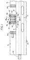
- a typical machine vise is indicated generally at 10 and includes a vise body 12 that has laterally extending rails 13 with top surfaces 14 that support and guide a first movable jaw 15, and in the form of the vise shown, a second movable jaw 16.
- the vise shown has a center fixed jaw 18, that is held securely relative to the vise body 12.
- the jaw plates 20 and 22 face the respective movable jaws 15 and 16, which have jaw plates 15A and 16A, mounted thereon, respectively.
- the vise is operated by operating a vise screw 24 to move the two jaws 15 and 16 toward and away from each other simultaneously.
- the jaw plates 15A and 16A will clamp workpieces against the jaw plates 20 and 22, respectively.
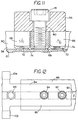
- the fixed jaw 18 is held in position on the vise body 12 with suitable cap screws 26 as shown in Figure 2. Also, keys shown in dotted lines at 28 can be used for holding the fixed jaw 18 in position on the vise.
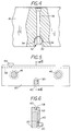
- the fixed jaw 18 has a locator cross pin 30 mounted in a centering slot 32 on the lower side of the fixed jaw 18.
- the locator pin 30 is held positively in place, and has outer ends 38 that extend out from the fixed jaw 18 and which are used for locating the jaw plates 20 and 22.
- the cross slot 32 that is formed in the lower edge of the fixed jaw is shown in Figure 4.
- the slot 32 has inwardly tapered end surfaces 34 near its inner or upper end to form a "V" seat for pin 30.
- the surfaces are angled so that the locator pin 30 has line contact along the surfaces 34 when the pin is seated and will center on the surfaces 34.
- the pin 30 has clearance at the upper end of slot 32.
- the locator pin 30 is pulled up against the surfaces 34 using a pull bolt 36 that has a head in a recess in the upper surface of the fixed jaw 18 and which threads into a threaded bore in the locator pin 30.
- the locator pin 30 end portions 38, 38 protrude out beyond the side surfaces of the fixed jaw 18, and the end portions are received in locator slots 40 and 42 in the jaw plates 20 and 22, respectively.
- the slots 40 and 42 are blind slots, and do not extend all the way through the jaw plates 20 and 22.
- Figures 5 and 6 show slot 40 typically.
- the slots 40 and 42 have parallel sides, and are made so that when the jaw plates rest on the surfaces 14 of the vise, there is a clearance at the top end of the slots 40 and 42 relative to the end portions 38 of the locator pin 30.
- jaw plates 20 and 22 are held in place with suitable cap screws that thread into the fixed jaw in a normal manner. Such cap screws are shown schematically at 46 in Figures 2, 3 and 5. Jaw plates 20 and 22 can be held against the surfaces of the fixed jaw 18 in any desired manner.
- each of the end portions 38 of the locator pin 30 have a slit 48 extending parallel to but offset from the pin central axis.
- the slot 48 extends inwardly from one end of the pin 30 to form a resilient locator portion 50 and a relatively fixed portion 52 of the end 38.
- the locator portion 50 will move toward the fixed portion 52 under a force and will exert a spring load outwardly.
- the slots 40 and 42 are made so that their width is less than the outer dimension of the locating pin 30 and specifically less than the locating pin end 38, so that when the jaw plates 20 and 22 are slid down into place against the fixed jaw 18 and over the end portions 38 of the locator pin 30, the jaw plates 20 and 22 cause locator portion 50 to resiliently move as they fit into the slots 40 and 42 and exert a spring load against the one side surface of the slots 40 and 42.
- the jaw plates are positively positioned laterally in direction of the longitudinal length of the jaw plates. This is the direction transverse to the axis of the movement of the movable jaws of the vise.
- the spring load from the resiliently loaded locator portion 50 provides a positive seating of the jaw plates 20 and 22, and as will be explained, that permits the jaw plates 20 and 22 to be interchanged with other jaw plates with the work stops set for particular piece parts carried thereon.
- the cap screws 46 are threaded into bores in the fixed jaw 18 so that the jaw plates 20 and 22 are securely held against the face of the fixed jaw 18.
- a work stop 56 is shown on each of the jaw plates 20 and 22 in Figure 2.
- the work stops have stop ends 57 that extend out from the clamp face of the jaw plate and are positioned in a location which provides for a stop for a workpiece to be held in the vise and machined.
- each of the jaw plates has a locator groove or slot 58 therein.
- the groove or slot has precisely spaced parallel side surfaces 60 and 62 and a bottom surface that joins these side surfaces.
- the bottom surface is positioned sufficiently deep to form a clearance relative to the holding or lock mechanisms for the work stop 58.
- the surfaces 60 and 62 are precisely machined parallel to each other and extending along the length of the jaw plates, which is the direction transverse to the direction of jaw movement for clamping.
- the work stops 56 can be held in any desired location along the length of these grooves or slots 58, and can be made so that they will extend out beyond the ends of the vise jaws for parts that protrude beyond the sides of the vise.
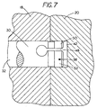
- FIG 8 is an enlarged fragmentary view of the top end of the jaw plate 20 and shows a work stop 56 in position.
- the slot or groove 58 is shown, and it can be seen that the work stop 56 has a pair of spaced apart fixed lock members 66 (see also Figures 9, 10 and 11) that fit into the slot 58.
- the lock members 66 have inclined wedge surfaces 68 on one side and vertical side surfaces 70 opposite from the inclined surfaces.
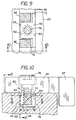
- the fixed lock members 66 are on opposite ends of the work stop body 55, and the lock members 66 are spaced apart in the center sufficient to receive a tongue 69 of a movable lock member or portion 71.
- Movable lock member 71 has outwardly extending wedges 72 on opposite sides of its center line, and the wedges 72 have upwardly facing inclined surfaces 74 which align with and mate with the surfaces 68 on fixed lock members 66. This can perhaps best be seen in Figure 9, where the lock members 66 have been broken away, and are shown overlying partially the inclined surfaces 74 of the wedges 72.
- the lock member 71 also has a vertical side surface 76 that is adjacent to and will engage the side surface 60 of the slot 58.
- a cap screw 78 is positioned in the body 55 of the work stop 56, and extends through a bore 80 to be threaded into a threaded opening in the tongue portion 69 of the movable lock member 71.
- the wedge surfaces 68 and 74 will engage and slide, tending to expand the overall width of the member represented in Figure 10 at W, thereby tightening the lock members to cause wedging so the surfaces 70 and 76 expand against the surfaces 60 and 62 of the slot 58.
- a work stop 56 can be slid along the length of the slot 58 of either one of the jaw plates, and clamped in place by tightening the screw 78 to form the wedge locking arrangement caused by the surfaces 70 and 76 that expand laterally to hold the work stop positively in position.
- the work stop 56 can be left in position for a particular part and the jaw plate removed, and when the same part is to be machined the jaw plate can be replaced because of the precise locating arrangement laterally using locator pin 30 as well as against the surface of the fixed jaw 18.
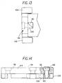
- a work stop such as that shown in Figures 12, 13 and 14 can be utilized.
- a work stop 84 has an elongated body 86 that lies over top of a jaw plate 88 that has a groove or slot 90 in the top edge.
- the same type of wedge lock members as shown in the first form of the invention can be utilized in three positions including a first position 92, a second position 94 and a third position 96.
- the work stop 84 can be locked positively in position and held in place in the slot as in the previous form of the invention.
- An outer end of the work stop can protrude beyond an end 100 of the jaw plate 88.
- the work stop body 86 has a pair of work stop lugs 102 and 104 extending in opposite directions from the jaw plate 88.
- the groove can be in a fixed jaw, such as that shown at 18 so that the lugs 102 and 104 can be used for stopping workpieces on opposite sides of the fixed jaw 18.
- the work stop lugs can be used as desired. It can also be seen that three stations can be used for locking the work stop 84 in position.
- the lock members 96 are the same type as that shown in the first form of the invention.
- the work stop 84 can have a plurality of the lock members spaced at appropriate locations for providing the expanding members that hold the work stop positioned securely.
- the work stop 84 can be made to extend either to the right or left of the vise.
- FIGS 15-21 show alternate locking arrangements for use with the work stops of the present invention.
- a work stop 110 has a body 111, and a lock member set screw 112 has a threaded shank threadably mounted in a bore in the center of the body 111.
- the portion end 144 of the set screw 112 is made eccentric relative to the central axis 116 of the threaded shank, and when the set screw 112 is turned, a cam surface shown at 118 will engage the side surface 62 of the slot or groove and force the opposite side of the end portion 144 against surface 60 to provide a cam lock for the work stop 110.
- the work stop lug 119 will thus be held securely at a desired position along the jaw plate. Releasing the lock member is accomplished by reversing the rotation of the set screw 112.
- Figure 16 shows a further modified form wherein a work stop 120 has a body 121 that has a lock portion 123 that extends into the slot 58.
- a threaded bore 122 is formed in the body 121 and lock portion 123 with the axis of the bore 122 at an acute angle relative to the plane of the surface 62 of the slot 58.
- a set screw 124 has an internal cone surface 126 adjacent its inner end and is positioned in the threaded bore 122.
- the set screw 121 can be loosened (screwed inwardly) so that the cone surface is inside the bore in the lock portion 123.
- the lock portion 123 and end portion 128 of the set screw can be slipped into the slot 58.
- the set screw is tightened (drawn upwardly) so that the conical surface 126 will engage the surface 62 and push the lock portion against surface 60 to securely lock the work stop 120 relative to the jaw plate 20.
- the lock portion 123 has a width along the slot 58 greater than the diameter of the set screw so it has a surface 125 that engages surface 60.
- the lock portion has a width as shown for the locks in Figures 19 and 21. Releasing is accomplished by reversing direction of rotation of the set screw. Only a partial turn of the set screw is needed for locking and releasing.
- the work stop 130 has a countersunk bore 132 in its body 133, and it has a recess 134 defined therein.
- the body 133 has a lock portion 135 that extends into the slot 58 of the jaw plate 20, and the recess 134 extends into the lock portion and slidably receives a locking wedge member 136.
- the locking wedge member is positioned so it will partially extend into the slot 58 adjacent surface 62.
- the recess 134 is open to that side so the wedge member 136 can move out of the lock member 135 to engage surface 62.
- the lock member 135 also has a lateral width along slot 58.
- a cap screw 137 is used for tightening the wedge member 136 upwardly and when this is done, the wedge member 136 will engage the side surface 62 of the slot 58 and cause an expanding force with the opposite side of the lock portion 135 including a lip portion 135 that extends into the slot 58, and the surface along the lateral width engaging surface 62. The wedge member 136 will securely hold the work stop 130 in position.
- FIGs 18 and 19 a further modified form of the invention is shown for holding a work stop 140 in position.
- the work stop 140 has a body 141 in which a threaded bore 142 is formed.
- the body 141 has a housing structure 144 that extends down into the slot 58 and forms a lock portion.
- housing 144 has an interior chamber 145.
- the chamber 145 has parallel side walls and is open to the surface 62 when the work stop is positioned in the slot 58.
- a compressible rubber block 136 is positioned in the chamber 145 near the lower end of the chamber, and a set screw 147 is threaded into the bore 143.
- the set screw has an end 148 that fits into the chamber 145 and bears against the rubber block 146.
- the rubber block 146 When the set screw 147 is tightened, the rubber block 146 will tend to expand outwardly in direction toward the surface 62 and will cause the work stop to be held securely by expanding the lateral dimension of the lock portion 144 and a movable lock portion comprising the expanding rubber block 146.
- the block 146 and lock portion 144 engage the surfaces 62 and 60 of the slot 58 for locking.
- Figures 20 and 21 show a further modified form of the work stop lock of the present invention.
- a work stop 154 has a body 155, and a threaded bore 156 through the body.
- the body 155 also has a lower lock housing 158 extending into the slot 58 of the jaw plate 20, and the body 158 is slightly narrower than the space between the surfaces 60 and 62 of the slot 58.
- Lower lock body 158 has a bore 160 therethrough, transverse to the slot and opening to both the surfaces 60 and 62, as shown.
- a cam plunger 162 is mounted in bore 160, and it has a conical seat 164 at an upper side thereof that aligns with the bore 156 in the body 155.
- a set screw 166 is threaded into the bore 156 and has a cone end 168 that fits into the conical recess 164.
- the center line 166A of the set screw 166 is off set from the center of the lock body 158 and offset from the center of the conical seat 164.
- the cone end 168 of the set screw thus will bear against one side of the conical shaped seat 164 and will force the plunger 162 against the surface 62.
- the opposite end of the lock body 150 will bear against the surface 60 of the slot 58 to cause a positive lock to occur.
- the system design allows positioning workpieces repeatably into a vise locating the workpiece or multiple workpieces with a minimum of accessories and allows mounting the vises in close proximity to each other without interference from the work stop.
- the work stops are contained within the "foot print" of the vise unless the work stop is needed for an extended part.
- the design allows jaw plates to be used that are no higher than the stationary jaw on which the jaw plates mount.
- the standard work stop is designed small enough in width so as it does not consume as much of the usable jaw clamping surface as existing work stops, and can be used to locate parts on either the right or left edge.
- the sides of the work stop bodies are ground parallel.
- the work stop will be usable on all jaw sizes, so long as the jaw has a groove, and can be used on fixed jaws or on jaw plates as shown.
- the jaw plate locator pin on the fixed jaw is positioned, located on the fixed jaw, and the resilient end portion of locator pin will cause the jaw plate to be located and referenced against one side of the provided slot, to positively position the jaw plate laterally.
- the jaw plate is held securely against the face of the stationary jaw for insuring that it is vertical.
- a minimum number of tools are necessary for operating the work stop. Generally only an Allen type wrench is needed for operating the work stops, and also for removing and replacing the jaw plates.
Landscapes
- Engineering & Computer Science (AREA)
- Mechanical Engineering (AREA)
- Gripping Jigs, Holding Jigs, And Positioning Jigs (AREA)
Applications Claiming Priority (2)
| Application Number | Priority Date | Filing Date | Title |
|---|---|---|---|
| US892258 | 1992-06-02 | ||
| US08/892,258 US6029967A (en) | 1997-07-11 | 1997-07-11 | Work stop system and jaw plate for holding the same |
Publications (2)
| Publication Number | Publication Date |
|---|---|
| EP0890419A2 true EP0890419A2 (de) | 1999-01-13 |
| EP0890419A3 EP0890419A3 (de) | 1999-04-21 |
Family
ID=25399663
Family Applications (1)
| Application Number | Title | Priority Date | Filing Date |
|---|---|---|---|
| EP98112659A Ceased EP0890419A3 (de) | 1997-07-11 | 1998-07-08 | Anschlagsystem und dieses festhaltende Backenplatte |
Country Status (2)
| Country | Link |
|---|---|
| US (2) | US6029967A (de) |
| EP (1) | EP0890419A3 (de) |
Cited By (1)
| Publication number | Priority date | Publication date | Assignee | Title |
|---|---|---|---|---|
| KR101013129B1 (ko) | 2010-11-01 | 2011-02-10 | 이호형 | 초소형 렌즈의 비구면 형상부를 성형하기 위한 핀 가공용 고정지그 |
Families Citing this family (12)
| Publication number | Priority date | Publication date | Assignee | Title |
|---|---|---|---|---|
| US6029967A (en) * | 1997-07-11 | 2000-02-29 | Kurt Manufacturing Company, Inc. | Work stop system and jaw plate for holding the same |
| US7021614B2 (en) * | 2002-11-27 | 2006-04-04 | Sean Hubbard | Truss assembly table with wedge set stop members |
| US7152855B1 (en) | 2004-04-07 | 2006-12-26 | Martens Michael R | Vise jaw with work stop |
| CA2635824A1 (en) * | 2007-06-29 | 2008-12-29 | Quickmill Inc. | Work piece support |
| US8408527B2 (en) * | 2008-11-10 | 2013-04-02 | Jergens, Inc. | Multiple jaw vise and method of making the same |
| US8256753B2 (en) * | 2009-06-17 | 2012-09-04 | Productivity Systems, Llc | High-density fixture vise |
| DE102014016631B4 (de) * | 2014-11-04 | 2018-10-25 | Michael Weinig Ag | Klemmvorrichtung für einen verstellbaren Anschlag einer Bearbeitungsmaschine, insbesondere einer Kehlmaschine, sowie Bearbeitungsmaschine, insbesondere Kehlmaschine, mit einer Klemmvorrichtung |
| US10179392B2 (en) * | 2015-01-23 | 2019-01-15 | Chris Taylor | Multi_station fixture vise |
| CN104971994A (zh) * | 2015-07-30 | 2015-10-14 | 嘉兴亨泰金属制品有限公司 | 一种模具夹具 |
| US10828749B1 (en) | 2016-08-26 | 2020-11-10 | Kurt Manufacturing Company, Inc. | Vise with improved stationary jaw |
| USD815507S1 (en) | 2016-08-26 | 2018-04-17 | Kurt Manufacturing Company, Inc. | Stationary jaw for a vise |
| CN113649830A (zh) * | 2021-08-05 | 2021-11-16 | 天润工业技术股份有限公司 | 曲轴加工定位装置及曲轴加工机床 |
Citations (5)
| Publication number | Priority date | Publication date | Assignee | Title |
|---|---|---|---|---|
| CH354045A (de) * | 1957-11-05 | 1961-04-30 | Ehrat Arnold | Einspannvorrichtung für Werkstücke wie Metallschilder usw. beim Gravieren derselben |
| DE1285418B (de) * | 1966-05-04 | 1968-12-12 | Weidmann Ernst | Klemmbacke fuer Maschinen- und Werkbankschraubstoecke |
| EP0126794A1 (de) * | 1983-05-30 | 1984-12-05 | Helmut Letzel | Vorrichtung zur elektromechanischen Steuerung und/oder Sicherung von Maschinenbewegungen |
| US4969637A (en) * | 1988-12-26 | 1990-11-13 | Kabushiki Kaisha Nishimura Jig | Work holder for vice |
| US5018562A (en) * | 1989-12-21 | 1991-05-28 | Adams Phillip A | Power tool fence system |
Family Cites Families (14)
| Publication number | Priority date | Publication date | Assignee | Title |
|---|---|---|---|---|
| GB1227732A (de) * | 1967-04-14 | 1971-04-07 | ||
| US3810311A (en) * | 1972-06-15 | 1974-05-14 | H Pingel | Locating stop for work to be machined or the like |
| US4030718A (en) * | 1974-03-20 | 1977-06-21 | Alexandros Philipoff | Universally adjustable vise stop |
| US4186916A (en) * | 1978-09-18 | 1980-02-05 | Salisbury Special Tool | Precision workpiece positioning means for machine tools |
| US4898371A (en) * | 1988-03-17 | 1990-02-06 | Mills Perry A | Quick-change vise |
| IT1229810B (it) * | 1988-11-11 | 1991-09-13 | Pirelli Cavi Spa | Procedimento ed apparecchiatura per inserire un supporto rigido in un manicotto per giunti di cavi elettrici. |
| US5078372A (en) * | 1989-10-12 | 1992-01-07 | Fitzpatrick John P | Quick change vise jaw |
| US5197721A (en) * | 1992-06-26 | 1993-03-30 | Mark Ruberg | Device for positioning workpieces in a milling machine vise |
| US5358364A (en) * | 1993-09-07 | 1994-10-25 | Kall Ronald J | Setup device and method for milling machines |
| US5649694A (en) * | 1995-05-23 | 1997-07-22 | Buck; James R. | Multiple jaw vise with floating actuator |
| US5735513A (en) * | 1996-03-15 | 1998-04-07 | Joseph F. Toffolon | Multi-station single action high precision mechanical vise |
| US6029967A (en) * | 1997-07-11 | 2000-02-29 | Kurt Manufacturing Company, Inc. | Work stop system and jaw plate for holding the same |
| DE29716103U1 (de) * | 1997-09-08 | 1999-01-14 | Gressel Ag | Spannvorrichtung, insbesondere Maschinenschraubstock |
| US6017026A (en) * | 1997-12-11 | 2000-01-25 | Durfee, Jr.; David L. | Machining vise |
-
1997
- 1997-07-11 US US08/892,258 patent/US6029967A/en not_active Expired - Lifetime
-
1998
- 1998-07-08 EP EP98112659A patent/EP0890419A3/de not_active Ceased
-
2000
- 2000-01-06 US US09/477,690 patent/US6217014B1/en not_active Expired - Fee Related
Patent Citations (5)
| Publication number | Priority date | Publication date | Assignee | Title |
|---|---|---|---|---|
| CH354045A (de) * | 1957-11-05 | 1961-04-30 | Ehrat Arnold | Einspannvorrichtung für Werkstücke wie Metallschilder usw. beim Gravieren derselben |
| DE1285418B (de) * | 1966-05-04 | 1968-12-12 | Weidmann Ernst | Klemmbacke fuer Maschinen- und Werkbankschraubstoecke |
| EP0126794A1 (de) * | 1983-05-30 | 1984-12-05 | Helmut Letzel | Vorrichtung zur elektromechanischen Steuerung und/oder Sicherung von Maschinenbewegungen |
| US4969637A (en) * | 1988-12-26 | 1990-11-13 | Kabushiki Kaisha Nishimura Jig | Work holder for vice |
| US5018562A (en) * | 1989-12-21 | 1991-05-28 | Adams Phillip A | Power tool fence system |
Cited By (1)
| Publication number | Priority date | Publication date | Assignee | Title |
|---|---|---|---|---|
| KR101013129B1 (ko) | 2010-11-01 | 2011-02-10 | 이호형 | 초소형 렌즈의 비구면 형상부를 성형하기 위한 핀 가공용 고정지그 |
Also Published As
| Publication number | Publication date |
|---|---|
| US6217014B1 (en) | 2001-04-17 |
| EP0890419A3 (de) | 1999-04-21 |
| US6029967A (en) | 2000-02-29 |
Similar Documents
| Publication | Publication Date | Title |
|---|---|---|
| US6029967A (en) | Work stop system and jaw plate for holding the same | |
| US5060920A (en) | Quick change jaw assembly for high precision machining | |
| US5623757A (en) | Two station machining vise with removable and off-setting jaws | |
| US4898371A (en) | Quick-change vise | |
| US4575293A (en) | Machine tool holder having opposed ramp members | |
| US6022010A (en) | Quick change jaw plate | |
| US5595376A (en) | Mandrel for processing a workpiece with an internal spline | |
| JP5611971B2 (ja) | インサートホルダをクランプするための工具ホルダ | |
| US8256753B2 (en) | High-density fixture vise | |
| GB2178985A (en) | A vice for clamping two works | |
| US5718420A (en) | Workholding wedge clamp | |
| US11110568B2 (en) | Convertible two station vise | |
| EP0229717B1 (de) | Schraubstock | |
| KR19990006862A (ko) | 축방향으로 조절 가능한 밀링 공구 | |
| US10343261B2 (en) | Vise stop arrangement | |
| US4139188A (en) | Machine vise | |
| US5505437A (en) | Two station machining vise with removable and off-settable jaws | |
| KR20180081238A (ko) | 클램핑 고정구 | |
| HU223859B1 (hu) | Forgácsolószerszám nagy sebességű megmunkáláshoz | |
| US6045126A (en) | Vise jaw and bolt | |
| JPH02243295A (ja) | ダイ締結装置 | |
| US5961108A (en) | Two-sided gripping device | |
| US5150888A (en) | Clamping mechanism in a vise jaw accessory system for attaching and releasing vise accessories while maintaining positional accuracy of the accessories | |
| US2764380A (en) | Support | |
| US4582306A (en) | Vise jaw |
Legal Events
| Date | Code | Title | Description |
|---|---|---|---|
| PUAI | Public reference made under article 153(3) epc to a published international application that has entered the european phase |
Free format text: ORIGINAL CODE: 0009012 |
|
| AK | Designated contracting states |
Kind code of ref document: A2 Designated state(s): DE FR GB IT |
|
| AX | Request for extension of the european patent |
Free format text: AL;LT;LV;MK;RO;SI |
|
| PUAL | Search report despatched |
Free format text: ORIGINAL CODE: 0009013 |
|
| AK | Designated contracting states |
Kind code of ref document: A3 Designated state(s): AT BE CH CY DE DK ES FI FR GB GR IE IT LI LU MC NL PT SE |
|
| AX | Request for extension of the european patent |
Free format text: AL;LT;LV;MK;RO;SI |
|
| 17P | Request for examination filed |
Effective date: 19991006 |
|
| AKX | Designation fees paid |
Free format text: DE FR GB IT |
|
| 17Q | First examination report despatched |
Effective date: 20001208 |
|
| GRAG | Despatch of communication of intention to grant |
Free format text: ORIGINAL CODE: EPIDOS AGRA |
|
| RIN1 | Information on inventor provided before grant (corrected) |
Inventor name: WOLFE, INGO E. |
|
| STAA | Information on the status of an ep patent application or granted ep patent |
Free format text: STATUS: THE APPLICATION HAS BEEN REFUSED |
|
| 18R | Application refused |
Effective date: 20020915 |