EP0890401A1 - Turret tool rest - Google Patents
Turret tool rest Download PDFInfo
- Publication number
- EP0890401A1 EP0890401A1 EP96941877A EP96941877A EP0890401A1 EP 0890401 A1 EP0890401 A1 EP 0890401A1 EP 96941877 A EP96941877 A EP 96941877A EP 96941877 A EP96941877 A EP 96941877A EP 0890401 A1 EP0890401 A1 EP 0890401A1
- Authority
- EP
- European Patent Office
- Prior art keywords
- turret
- tool
- indexing
- engage
- turning
- Prior art date
- Legal status (The legal status is an assumption and is not a legal conclusion. Google has not performed a legal analysis and makes no representation as to the accuracy of the status listed.)
- Granted
Links
- 238000007514 turning Methods 0.000 claims abstract description 60
- 230000005540 biological transmission Effects 0.000 claims abstract description 13
- 230000008878 coupling Effects 0.000 description 41
- 238000010168 coupling process Methods 0.000 description 41
- 238000005859 coupling reaction Methods 0.000 description 41
- 230000007246 mechanism Effects 0.000 description 18
- 238000005520 cutting process Methods 0.000 description 8
- 238000003754 machining Methods 0.000 description 7
- 230000002093 peripheral effect Effects 0.000 description 4
- 230000002547 anomalous effect Effects 0.000 description 3
- 238000010276 construction Methods 0.000 description 3
- 238000012790 confirmation Methods 0.000 description 2
- 238000013500 data storage Methods 0.000 description 2
- 238000010586 diagram Methods 0.000 description 2
- 230000002708 enhancing effect Effects 0.000 description 2
- 230000033001 locomotion Effects 0.000 description 2
- 239000011295 pitch Substances 0.000 description 2
- 230000002441 reversible effect Effects 0.000 description 2
- 238000005096 rolling process Methods 0.000 description 2
- 230000003247 decreasing effect Effects 0.000 description 1
- 238000005553 drilling Methods 0.000 description 1
- 238000005516 engineering process Methods 0.000 description 1
- 239000012530 fluid Substances 0.000 description 1
- 230000002452 interceptive effect Effects 0.000 description 1
- 238000004519 manufacturing process Methods 0.000 description 1
- 238000000034 method Methods 0.000 description 1
- 230000008569 process Effects 0.000 description 1
- 230000009467 reduction Effects 0.000 description 1
- 230000002829 reductive effect Effects 0.000 description 1
- 230000004044 response Effects 0.000 description 1
- 230000000452 restraining effect Effects 0.000 description 1
- 238000003860 storage Methods 0.000 description 1
Images


Classifications
-
- B—PERFORMING OPERATIONS; TRANSPORTING
- B23—MACHINE TOOLS; METAL-WORKING NOT OTHERWISE PROVIDED FOR
- B23B—TURNING; BORING
- B23B3/00—General-purpose turning-machines or devices, e.g. centre lathes with feed rod and lead screw; Sets of turning-machines
- B23B3/16—Turret lathes for turning individually-chucked workpieces
- B23B3/167—Turret lathes for turning individually-chucked workpieces lathe with two or more toolslides carrying turrets
- B23B3/168—Arrangements for performing other machining operations, e.g. milling, drilling
-
- B—PERFORMING OPERATIONS; TRANSPORTING
- B23—MACHINE TOOLS; METAL-WORKING NOT OTHERWISE PROVIDED FOR
- B23B—TURNING; BORING
- B23B9/00—Automatic or semi-automatic turning-machines with a plurality of working-spindles, e.g. automatic multiple-spindle machines with spindles arranged in a drum carrier able to be moved into predetermined positions; Equipment therefor
-
- B—PERFORMING OPERATIONS; TRANSPORTING
- B23—MACHINE TOOLS; METAL-WORKING NOT OTHERWISE PROVIDED FOR
- B23B—TURNING; BORING
- B23B29/00—Holders for non-rotary cutting tools; Boring bars or boring heads; Accessories for tool holders
- B23B29/24—Tool holders for a plurality of cutting tools, e.g. turrets
- B23B29/242—Turrets, without description of the angular positioning device
-
- B—PERFORMING OPERATIONS; TRANSPORTING
- B23—MACHINE TOOLS; METAL-WORKING NOT OTHERWISE PROVIDED FOR
- B23Q—DETAILS, COMPONENTS, OR ACCESSORIES FOR MACHINE TOOLS, e.g. ARRANGEMENTS FOR COPYING OR CONTROLLING; MACHINE TOOLS IN GENERAL CHARACTERISED BY THE CONSTRUCTION OF PARTICULAR DETAILS OR COMPONENTS; COMBINATIONS OR ASSOCIATIONS OF METAL-WORKING MACHINES, NOT DIRECTED TO A PARTICULAR RESULT
- B23Q16/00—Equipment for precise positioning of tool or work into particular locations not otherwise provided for
- B23Q16/02—Indexing equipment
- B23Q16/04—Indexing equipment having intermediate members, e.g. pawls, for locking the relatively movable parts in the indexed position
- B23Q16/06—Rotary indexing
- B23Q16/065—Rotary indexing with a continuous drive
-
- Y—GENERAL TAGGING OF NEW TECHNOLOGICAL DEVELOPMENTS; GENERAL TAGGING OF CROSS-SECTIONAL TECHNOLOGIES SPANNING OVER SEVERAL SECTIONS OF THE IPC; TECHNICAL SUBJECTS COVERED BY FORMER USPC CROSS-REFERENCE ART COLLECTIONS [XRACs] AND DIGESTS
- Y10—TECHNICAL SUBJECTS COVERED BY FORMER USPC
- Y10S—TECHNICAL SUBJECTS COVERED BY FORMER USPC CROSS-REFERENCE ART COLLECTIONS [XRACs] AND DIGESTS
- Y10S82/00—Turning
- Y10S82/905—Transmission accessory or control
-
- Y—GENERAL TAGGING OF NEW TECHNOLOGICAL DEVELOPMENTS; GENERAL TAGGING OF CROSS-SECTIONAL TECHNOLOGIES SPANNING OVER SEVERAL SECTIONS OF THE IPC; TECHNICAL SUBJECTS COVERED BY FORMER USPC CROSS-REFERENCE ART COLLECTIONS [XRACs] AND DIGESTS
- Y10—TECHNICAL SUBJECTS COVERED BY FORMER USPC
- Y10T—TECHNICAL SUBJECTS COVERED BY FORMER US CLASSIFICATION
- Y10T29/00—Metal working
- Y10T29/51—Plural diverse manufacturing apparatus including means for metal shaping or assembling
- Y10T29/5152—Plural diverse manufacturing apparatus including means for metal shaping or assembling with turret mechanism
- Y10T29/5154—Plural diverse manufacturing apparatus including means for metal shaping or assembling with turret mechanism tool turret
- Y10T29/5155—Rotary tool holder
-
- Y—GENERAL TAGGING OF NEW TECHNOLOGICAL DEVELOPMENTS; GENERAL TAGGING OF CROSS-SECTIONAL TECHNOLOGIES SPANNING OVER SEVERAL SECTIONS OF THE IPC; TECHNICAL SUBJECTS COVERED BY FORMER USPC CROSS-REFERENCE ART COLLECTIONS [XRACs] AND DIGESTS
- Y10—TECHNICAL SUBJECTS COVERED BY FORMER USPC
- Y10T—TECHNICAL SUBJECTS COVERED BY FORMER US CLASSIFICATION
- Y10T408/00—Cutting by use of rotating axially moving tool
- Y10T408/36—Machine including plural tools
- Y10T408/37—Turret of tools
-
- Y—GENERAL TAGGING OF NEW TECHNOLOGICAL DEVELOPMENTS; GENERAL TAGGING OF CROSS-SECTIONAL TECHNOLOGIES SPANNING OVER SEVERAL SECTIONS OF THE IPC; TECHNICAL SUBJECTS COVERED BY FORMER USPC CROSS-REFERENCE ART COLLECTIONS [XRACs] AND DIGESTS
- Y10—TECHNICAL SUBJECTS COVERED BY FORMER USPC
- Y10T—TECHNICAL SUBJECTS COVERED BY FORMER US CLASSIFICATION
- Y10T82/00—Turning
- Y10T82/25—Lathe
- Y10T82/2508—Lathe with tool turret
-
- Y—GENERAL TAGGING OF NEW TECHNOLOGICAL DEVELOPMENTS; GENERAL TAGGING OF CROSS-SECTIONAL TECHNOLOGIES SPANNING OVER SEVERAL SECTIONS OF THE IPC; TECHNICAL SUBJECTS COVERED BY FORMER USPC CROSS-REFERENCE ART COLLECTIONS [XRACs] AND DIGESTS
- Y10—TECHNICAL SUBJECTS COVERED BY FORMER USPC
- Y10T—TECHNICAL SUBJECTS COVERED BY FORMER US CLASSIFICATION
- Y10T82/00—Turning
- Y10T82/25—Lathe
- Y10T82/2531—Carriage feed
- Y10T82/2537—Apron mechanism
- Y10T82/2539—Feednut control
-
- Y—GENERAL TAGGING OF NEW TECHNOLOGICAL DEVELOPMENTS; GENERAL TAGGING OF CROSS-SECTIONAL TECHNOLOGIES SPANNING OVER SEVERAL SECTIONS OF THE IPC; TECHNICAL SUBJECTS COVERED BY FORMER USPC CROSS-REFERENCE ART COLLECTIONS [XRACs] AND DIGESTS
- Y10—TECHNICAL SUBJECTS COVERED BY FORMER USPC
- Y10T—TECHNICAL SUBJECTS COVERED BY FORMER US CLASSIFICATION
- Y10T82/00—Turning
- Y10T82/25—Lathe
- Y10T82/2585—Tool rest
- Y10T82/2587—Turret type holder [e.g., multiple tools, etc.]
Definitions
- the present invention relates to a turret device to be used in a working machine such as an NC lathe.
- the turret device is structured such that a rotary table called a turret which is provided on a tab base table (tool slide), and has normally 5 to 12 indexing positions, is indexed while rotated (hereinafter referred to as simply indexed).
- Tool mounting portions are formed on an outer periphery or end surface of the turret, and various tools such as turning tools and drills are mounted on these tool mounting portions wherein an appropriate tool is selected from the various tools depending on the type of machining process desired so as to index the selected tools in machining positions.
- Such an indexing of the turret is performed by the driving force from an indexing actuator.
- the turning tools and drills can be frequently mounted on the tool mounting portions of the turret, wherein machining such as drilling a hole into a workpiece can be performed by driving the turning tools mounted on the tool mounting portions.
- the motor for driving the turning tool is provided in addition to the motor for indexing the turret, whereby the turning tool is driven and turned by a driving force of the motor for driving the turning tool, thereby performing the machining of the workpiece.
- the driving source for positioning and fixing the turret comprises the electric motor, the reduction of components and the easy control are further enhanced.
- the present invention Since the present invention has been made in view of the above concept, it provides a turret device capable of achieving the indexing of the turret and the driving of the turning tool by a common electric actuator, thereby eliminating the power unit.
- a first aspect of the invention is characterized in comprising the following construction in a turret device comprising a base table, a turret which is indexed about a given rotary center relative to the base table, and positioning engaging members which are provided between the base table and the turret so as to be engageable with or disengageable from each other for preventing the turret from turning when they engage with each other.
- the turret device further comprises:
- the indexing of the turret and the driving of the turning tool can be performed by one electric actuator. That is, the driving force of the electric actuator for indexing the turret is transmitted to the turning tool via the power transmission member. It is necessary that the transmission of the driving force of the electric actuator to the turret be performed merely when the turret is indexed, and the driving force from the electric actuator is not transmitted to the turret when the turning tool is turned upon completion of indexing of the turret.
- the clutch members permit the electric actuator and turret to engage with or disengage from each other, and they transmits the driving force of the electric actuator to the turret merely when the turret is indexed.
- the transmission between the electric actuator and turret by the clutch members, and engagement and disengagement between the positioning engaging members are respectively performed by the engaging means while they are interlocked with each other. That is, the engaging means permits the clutch members to engage with each other interlocking with the disengagement between the positioning engaging members while permitting the clutch members to disengage with each other interlocking with the engagement between the positioning engaging members. As a result, the engagement and disengagement between the positioning engaging members and those of the clutch means can be easily controlled.
- a second aspect of the invention is characterized in comprising the following construction in a turret device comprising a base table, a turret which is indexed about a given rotary center relative to the base table, and positioning engaging members which are provided between the base table and the turret so as to be engageable with or disengageable from each other for preventing the turret from turning when they engage with each other, comprising:
- the engaging means is driven by the second electric actuator, thereby eliminating a power unit which is required for a hydraulic cylinder, reducing the cost of parts, and enhancing the easy control.
- the second electric actuator is not limited to the electric motor but may be formed of an electric cylinder, etc.
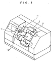
- Fig. 1 is a perspective view showing an external configuration of the turret NC lathe.
- the turret NC lathe comprises a headstock 1 and a turret device 2.
- the headstock 1 has a chuck 3 mounted thereon for holding a workpiece, and the headstock 1 serves to rotate the workpiece held by the chuck 3 by a main spindle motor (not shown) incorporated therein.
- a turret 11 (two turrets 11 with the workpiece interposed therebetween in Fig. 1) is provided on the turret device 2 for appropriately selecting the tool and cutting the workpiece held by the chuck 3 of the headstock 1.
- the cutting process can be performed by moving a tool slide 4 provided on the turret device 2 in the direction of a main spindle center line (Z axis) and in the direction of an X axis which crosses at right angles with the main spindle center line.
- Fig. 2 is a sectional plan view of the turret device according to the preferred embodiment of the invention.
- the turret device 2 comprises a base table 10 provided on the tool slide 4 and a turret 11 which is rotatably mounted on the base table 10.
- the tool slide 4 is driven in the directions of the Z and X axes by a tool slide driving apparatus, not shown.
- a plurality of tool mounting portions 12 are provided on a front end outer peripheral edge of the turret 11 with given indexing angles.
- a cutting tool 13 such as a turning tool secured to a tool holder 15 and a rotary tool 14 such as a drill secured to another tool holder 16 can be mounted on the tool mounting portions 12.
- the tool holder 15 of the cutting tool 13 can be firmly fixed to the tool mounting portion 12 such that a protrusion 15a formed on the tool holder 15 is inserted into and positioned in a mounting hole 12a defined in the tool mounting portion 12, and they are firmly fixed to each other by a fastening device such as a bolt, not shown.
- the tool holder 16 of the rotary tool 14 has a rotatable tool rotary shaft 17 which penetrates the center of a holder body 16a, and a tool chuck 18 for holding the rotary tool 14 is provided at the tip end of the tool rotary shaft 17. Further, a tool rotary gear 19 is provided at the base end of the tool rotary shaft 17.
- the tool holder 16 of the rotary tool 14 is firmly fixed to the tool mounting portion 12 such that the holder body 16a is inserted into the mounting hole 12a which is bored in the tool mounting portion 12 of the turret 11, and they are firmly fixed to each other by a fastening device such as a bolt, not shown.
- a fastening device such as a bolt
- the tool mounting portions 12 of the turret 11 and the tools may be structured in the same manner as the known turret and mounting tools which are applied to machine tools in addition to the aforementioned structure.
- a base end portion 11a formed in the small diameter part of the turret 11 is rotatable about a rotary center O via a slide bearing 20 formed in a hollow part 10a of the base table 10, and it is mounted on the base table 10 to be movable linearly along the rotary center O.
- a ball screw 21 is provided in the hollow part 10a of the base table 10 coaxially with the rotary center O via a rolling bearing 22.
- a motive transmission gear 23 is secured to the base end of the ball screw 21.
- a switching motor 24 (second electric actuator) formed of a servomotor is mounted on the base table 10.
- a driving gear, not shown, meshing with the motive transmission gear 23 is secured to the rotary shaft of the switching motor 24, wherein the driving force of the switching motor 24 is transmitted to the ball screw 21 via the driving gear and the motive transmission gear 23 so as to drive and turn the ball screw 21.
- a nut 25 is screwed into the ball screw 21, and it is fixed to the base end portion 11a of the turret 11. Accordingly, the nut 25 moves linearly along the rotary center O as the ball screw 21 turns so that the turret 11 moves linearly along the rotary center O together with the nut 25. That is, the ball screw 21 and nut 25 structure or comprise a screw feed mechanism 26 for linearly moving the turret 11.
- the turret 11 has an annular gear 29 which is mounted coaxially to the rotary center O via a needle bearing 28.
- a recess 30 defined in the outer peripheral surface of the turret 11 serves as an inner ring of the needle bearing 28 so that the needle bearing 28 can be rotated relative to the turret 11 but is prevented from moving in the direction of the rotary center O. Accordingly, the needle bearing 28 moves together with the turret 11 in the same direction when the turret 11 moves linearly along the rotary center O.
- the annular gear 29 is structured, as shown largely in Figs. 3 and 4, so that a circumferential groove 29a defined in the rear end thereof engages with a protrusion 10b formed on the base table 10, wherein the annular gear 29 is held in a given position by the engagement between the groove 29a and protrusion 10b.
- the hollow part 10a of the base table 10 has a large diameter part at the tip end side demarcating a stepped part 10c while the turret 11 has a large diameter part at the tip end side thereof demarcating a stepped part 11b.
- the stepped part 10c of the base table 10 and stepped part 11b of the turret 11 are provided with the positioning engaging member 27 at the surfaces thereof comprising a base table side coupling 27a and a turret side coupling 27b to form a curvic coupling.
- the couplings 27a and 27b are positioned with tooth profiles formed like a known crown gear meshing with each other, and they have inclined tooth profiles 27c respectively formed with given pitches as shown in Figs. 7A and 7B.
- the turret side coupling 27b fixed to the turret 11 moves in a direction denoted by a, tooth profiles 27c of the base table side coupling 27a and those of the turret side coupling 27b engage with each other or disengage from each other.
- Clutch pieces 31a and 31b constituting a clutch member 31 are respectively formed at the rear end edge of the annular gear 29 and at the front surface of the turret side coupling 27b of the positioning engaging member 27 provided on the turret 11 so as to oppose each other.
- Inclined tooth profiles are formed on the surfaces of the clutch pieces 31a and 31b opposing each other with given pitches like those of the couplings 27a and 27b. These tooth profiles engage with or disengage from each other when the turret 11 moves linearly along the rotary center 0.
- Fig. 3 is an enlarged view showing a state where the couplings 27a and 27b of the positioning engaging member 27 engage with each other to prevent the rotation of the turret 11 and the clutch pieces 31a and 31b of the clutch member 31 disengage from each other.
- the turret 11 Since the turret 11 is prevented from rotating by the engagement between the couplings 27a and 27b in the state shown in the same figure, it cannot be indexed. When the turret 11 moves leftward relative to the base table 10 by the turning of the ball screw 21 as shown in Fig. 2, the couplings 27a and 27b disengage from each other, then the clutch pieces 31a and 31b engage with each other.
- Fig. 4 is an enlarged view showing a state where the couplings 27a and 27b disengage from each other and the clutch pieces 31a and 31b engage with each other.
- the tool rotary gear 19 provided on the tool holder 16 of the rotary tool which is mounted on the tool mounting portion 12 of the turret 11 meshes with the annular gear 29.
- the indexing/tool turning motor 32 formed of a servomotor which serves as a first electric actuator for indexing the turret and driving the turning tool is mounted on the base table 10, and the driving force of the indexing/tool turning motor 32 is transmitted to the annular gear 29 via a gear mechanism 33 so as to rotate the annular gear 29.
- the indexing/tool turning motor 32 rotates the annular gear 29 via the gear mechanism 33 in the state shown in Fig. 3 so that only the tool rotary shaft 17 provided on the tool holder 16 is rotated by the rotation of the annular gear 29 to drive and turn the rotary tool 14. Meanwhile, in the state shown in Fig. 4 where the couplings 27a and 27b disengage from each other and the clutch pieces 31a and 31b engage with each other, the rotation of the annular gear 29 is transmitted to the turret side coupling 27b fixed to the turret 11 so that the indexing/tool turning motor 32 indexes the turret 11.
- the annular gear 29 also serves as a power transmission member for transmitting the driving force of the indexing/tool turning motor 32 to the rotary tool 14 mounted on the tool mounting portions 12.
- the annular gear 29 also serves as another power transmission member for transmitting the driving force of the indexing/tool turning motor 32 to the turret 11.
- the clutch member 31 comprising the clutch pieces 31a and 31b serves to transmit or not to transmit the driving force from the indexing/tool tuning motor 32 to the turret 11 via the annular gear 29.
- the screw feed mechanism 26 which is driven by the switching motor 24 forms an engaging means for permitting the positioning engaging members 27 to engage with or disengage from each other and for permitting the clutch members 31 to engage with or disengage from each other in reverse to the positioning engaging members 27.
- Fig. 5 is a block diagram showing a control system of the aforementioned turret device indexing/tool turning motor 32
- control system of the turret device 2 includes a control part (CPU) 40, a ROM/RAM 41, a data storage part 42, an input part 43, a display part 44, a main spindle driver 45, a switching motor driver 46, an indexing/tool turning motor driver 47, a tool slide driver 48, a tool replacement position detecting sensor 49, a coupling sensor 50, a clutch sensor 51, an indexing sensor 52, etc.
- a control program for driving the turret device 2 is stored in advance in the ROM/RAM 41.
- the control part 40 controls each component of the turret device 2 based on the control program.
- the input part 43 comprises a keyboard, etc., and data necessary for controlling each component of the turret device 2 (selection of tools, shapes and dimensions of the workpiece to be machined, rotating speed of the main spindle, feeding speed of tools, etc.) are inputted through the input part 43. This data can be inputted by entering numerical values on a drawing displayed on the display part 44 on an interactive basis.
- Data inputted from the input part 43 and various data necessary for driving and controlling the turret device 2 are respectively stored in the storage part 42.
- the control part 40 outputs a given command based on the control program stored in the ROM/RAM 41, on the selection of tools (indexing of the turret) as stored in the data storage part 42, and on machining data.
- the main spindle driver 45 drives a main spindle motor based on commands issued from the control part 40 to rotate the workpiece held by the chuck 3 of the headstock 1.
- the workpiece is machined by the movement of the tool slide 4 in the directions of the Z and X axes and by rotation of the rotary tool 14 by the indexing/tool turning motor 32, if necessary.
- the tool slide driver 48 drives the feed motor in the directions of the Z and X axes based on commands issued from the control part 40 to drive the tool slide 4 of the turret device 2 in the directions of the Z and X axes.
- the switching motor driver 46 drives the switching motor 24 based on a command issued from the control part 40 so as to permit the couplings 27a and 27b to engage with or disengage from each other and to permit the clutch pieces 31a and 31b to engage with or disengage from each other for positioning and fixing the turret 11.
- the indexing/tool turning motor driver 47 drives the indexing/tool turning motor 32 based on a command issued from the control part 40 so as to execute the indexing of the turret 11 or rotary driving of the rotary tool 14.
- the rotary driving of the rotary tool 14 is carried out when the workpiece is machined while the indexing of the turret 11 is carried out when the tools are selected before or after the workpiece is machined.
- the tool replacement position detecting sensor 49 detects whether the turret device 2 is positioned in a tool replacement position (i.e., a given backward position, namely, tool origin of the tool slide 4 where the turret 11 can be indexed) or not based on the coordinate showing the present position of the tool slide 4.
- a tool replacement position i.e., a given backward position, namely, tool origin of the tool slide 4 where the turret 11 can be indexed
- the coupling sensor 50 monitors the engagement and disengagement between the couplings 27a and 27b, and detects the increase of rotary torque of the switching motor 24 and outputs a coupling completion signal to the control part 40 upon completion of engagement between the couplings 27a and 27b.
- the clutch sensor 51 monitors the engagement and disengagement between the clutch pieces 31a and 31b, and outputs a clutch completion signal to the control part 40 when they engage with each other.
- the indexing sensor 52 monitors the rotary angle when the turret 11 is indexing, and outputs an indexing completion signal to the control part 40 when the indexing operation is completed at the angular position which is issued by the control part 40.
- these sensors 49 to 52 are structured to operate when detecting the rotary position of the servomotor or the variation of the rotary torque, a special sensor need not be provided.
- Fig. 6 is a flow chart showing a control operation for executing the indexing, positioning and fixation of the turret 11 of the turret device 2, and the rotary driving of the rotary tool 14 based on the control system having the structure set forth above.
- the control operation is executed mainly by the commands issued from the control part 40. Accordingly, the control operation set forth hereunder will be explained mainly with reference to the commands issued from the control part 40.
- the indexing/tool turning motor 32 serves as a driving source for executing the indexing of the turret 11 and rotary driving of the rotary tool 14. Since the rotating speed and rotating direction of the indexing/tool turning motor 32 are differentiated depending on the objects to be driven thereby, the control of the indexing/tool turning motor 32 is divided into a mode (T/I mode) for indexing the turret 11 and another mode (T/S mode) for rotary driving the rotary tool 14, wherein control programs corresponding to each mode are stored in the ROM/RAM 41.
- the control part 40 starts the indexing of the turret 11 upon confirmation of the completion of the cutting process, then switches the control program of the indexing/tool turning motor 32 to the T/I mode (S1), and successively confirms whether the turret device 2 is positioned or not at present at the tool origin (a tool replacement position where the turret device 2 is rotated) (S2) in response to a signal issued from the tool replacement position detecting sensor 49. If the turret device 2 is not positioned at the tool origin, the control part 40 outputs a moving command signal to the tool slide driver 48 (S3), and then moves the tool slide 4 of the turret device 2 to the tool origin.
- the control part 40 Upon confirmation that the turret device 2 is positioned at the tool origin, the control part 40 issues a driving command to the switching motor driver 46 to drive the switching motor 24 in the forward direction (S4).
- a rotating direction of the switching motor 24 for moving the nut 25 of the screw feed mechanism 26 in the forward direction is defined as the forward direction.
- the turret 11 Since the turret 11 is fixed to the nut 25, the turret 11 also moves forward linearly together with the nut 25. As a result, the couplings 27a and 27b of the positioning engaging member 27 provided between the base table 10 and turret 11 disengage from each other so that the turret 11 is rotatable.
- the friction between the ball screw 21 and nut 25 of the screw feed mechanism 26 is sufficiently small compared with that between the base end portion 11a of the turret 11 and slide bearing 20 of the base table 10, so that the turret 11 does not rotate but moves forward linearly.
- control part 40 Since the control part 40 has a timer function, it measures time counting from the time of issuance of the driving command to the switching motor driver 46 (S6), and it decides that the apparatus is anomalous when the clutch completion signal is not inputted therein even if a given time elapses, then it stops the operation of the turret device 2, then indicates an alarm (S7).
- the control part 40 stops the rotation of the switching motor 24, then issues a driving command to the indexing/tool turning motor driver 47 (S8), thereby rotating the indexing/tool turning motor 32 in the rotating direction and rotating angle which are determined by the present tool fixing position and the tool fixing position to be selected next.
- the driving force of the indexing/tool turning motor 32 is transmitted to the turret 11 via the gear mechanism 33, annular gear 29, and clutch pieces 31a and 31b. Based on this driving force, the turret 11 is indexed to the tool fixing position to be selected next.
- the nut 25 of the screw feed mechanism 26 fixed to the turret 11 is turned together with the turret 11.
- the ball screw 21 moves relatively linearly along the rotary center O by the relative turning of the nut 25.
- the ball screw 21 is prevented from moving in the direction of the rotary center O by the rolling bearing 22.
- the nut 25 moves and the turret 11 moves in the direction of the rotary center O.
- the switching motor 24 rotates in a given rotating direction with a given ratio of rotating speed so as not to rotate the ball screw 21 and nut 25 of the screw feed mechanism 26 relative to each other in synchronisation with the rotation of the indexing/tool turning motor 32 for indexing the turret 11.
- the ratio of rotating speed and rotating direction between the indexing/tool turning motor 32 and switching motor 24 are respectively determined by the ratio of a train of gears and rotating direction of gears extending from the indexing/tool turning motor 32 to annular gear 29 (turret 11) and those extending from the switching motor 24 to ball screw 21, and by a control program stored in the ROM/RAM 41.
- the control part 40 detects the rotating position of the indexing/tool turning motor 32 so that an indexing completion signal is issued from the indexing sensor 52 (S9).
- the control part 40 measures time counting from the time of issuance of the driving command to the indexing/tool turning motor driver 47 (S10), and it decides that the apparatus is anomalous when the clutch completion signal is not inputted therein even if a given time elapses, then it stops the operation of the turret device 2, then indicates an alarm (S7).
- the control part 40 stops the rotation of the indexing/tool turning motor 32, then issues the driving command to the switching motor driver 46 to rotate the switching motor 24 in an opposite direction (S11).
- the control part 40 measures time counting from the time of issuance of the reverse rotation driving command to the switching motor driver 46 (S13), and it judges that the apparatus is anomalous and stops the operation of the turret device 2, then indicates an alarm when the coupling completion signal is not inputted even if a given time elapses (S7).
- the control part 40 switches the control mode of the succeeding indexing/tool turning motor 32 to the rotary driving mode (T/S mode) of the rotary tool 14 (S14) and lowers the output torque of the switching motor 24 (S15).
- the output torque of the switching motor 24 is applied between the couplings 27a and 27b via the screw feed mechanism 26, and it is decreased to a torque (holding torque) for sufficiently keeping the engagement between the couplings 27a and 27b.
- the couplings 27a and 27b comprise curvic couplings, and the linear motion of the turret 11 is performed by the screw feed mechanism 26, the holding torque can be reduced to a sufficiently small torque.
- the screw feed mechanism 26 may be structured such that the nut 25 is positioned at the driving side while the ball screw 21 is positioned at the driven side.
- the ball screw 21 is fixed to the turret 11, and the ball screw 21 moves linearly by the turning of the nut 25 which can merely turn but does not move in the axial direction so that the turret 11 integrated with the ball screw 21 moves along the rotary center O, thereby forming the screw feed mechanism 26 in exactly the same manner as the case set forth above.
- screw feed mechanism 26 does not require low friction and high accuracy, an ordinary screw may be used instead of the ball screw 21.
- a means for restraining the rotation of the turret 11 e.g. a key and a spline which disengage from each other at the position where the clutch pieces 31a and 31b engage with each other
- a means for restraining the rotation of the turret 11 e.g. a key and a spline which disengage from each other at the position where the clutch pieces 31a and 31b engage with each other
- Hirth couplings, etc., having the same structures as the curvic couplings may be used as the aforementioned positioning engaging members 27 in addition to the curvic couplings.
- a friction coupling (brake) having a sufficient braking force or a shot pin can be used as a positioning means instead of the couplings 27a and 27b as shown in Fig. 2, etc.
- the engaging means of the positioning engaging members 27 and the clutch member 31 is formed of the screw feed mechanism 26 which is driven by the switching motor 24 but it may be formed of fluid pressure such as hydraulic pressure or pneumatic pressure so as to move the turret 11 in the axial direction.
- the turning of the turret and the driving of the turning tools can be performed by a common driving motor, thereby making the turret device small-sized, reducing the cost of the parts, and enhancing the easy control.
Abstract
Description
Claims (2)
- In a turret device comprising a base table, a turret which is indexed about a given rotary center relative to the base table, and positioning engaging members which are provided between the base table and the turret so as to be engageable with or disengageable from each other for preventing the turret from turning when they engage with each other, said turret device further comprising:an electric actuator for indexing the turret;clutch pieces for transmitting or not transmitting a driving force of the electric actuator to the turret;tool mounting portions provided on the turret;a power transmission member for transmitting the driving force of the electric actuator to turning tools mounted on the tool mounting portions; andan engaging means for permitting the positioning engaging members to engage with or disengage from each other, permitting the clutch pieces to engage with each other while interlocking with the disengagement between the positioning engaging members, and permitting the clutch pieces to disengage from each other while interlocking with the engagement between the positioning engaging members.
- In a turret device comprising a base table, a turret which is indexed about a given rotary center relative to the base table, and positioning engaging members which are provided between the base table and the turret so as to be engageable with or disengageable from each other for preventing the turret from turning when they engage with each other, said turret device further comprising:a first electric actuator for indexing the turret;clutch pieces for transmitting or not transmitting a driving force of the first electric actuator to the turret;an engaging means for not transmitting the driving force of the first electric actuator to the turret when the positioning engaging members engage with each other; anda second electric actuator for driving the engaging means.
Applications Claiming Priority (1)
| Application Number | Priority Date | Filing Date | Title |
|---|---|---|---|
| PCT/JP1996/003660 WO1998025722A1 (en) | 1996-12-13 | 1996-12-13 | Turret tool rest |
Publications (3)
| Publication Number | Publication Date |
|---|---|
| EP0890401A1 true EP0890401A1 (en) | 1999-01-13 |
| EP0890401A4 EP0890401A4 (en) | 1999-03-17 |
| EP0890401B1 EP0890401B1 (en) | 2002-10-09 |
Family
ID=14154225
Family Applications (1)
| Application Number | Title | Priority Date | Filing Date |
|---|---|---|---|
| EP96941877A Expired - Lifetime EP0890401B1 (en) | 1996-12-13 | 1996-12-13 | Turret tool rest |
Country Status (7)
| Country | Link |
|---|---|
| US (1) | US6016729A (en) |
| EP (1) | EP0890401B1 (en) |
| JP (1) | JP3253974B2 (en) |
| KR (1) | KR100264642B1 (en) |
| DE (1) | DE69624269T2 (en) |
| TW (1) | TW340076B (en) |
| WO (1) | WO1998025722A1 (en) |
Cited By (1)
| Publication number | Priority date | Publication date | Assignee | Title |
|---|---|---|---|---|
| CN104759651A (en) * | 2015-04-15 | 2015-07-08 | 常州优思塔精密机械有限公司 | Axial power tool turret of built-in power motor |
Families Citing this family (17)
| Publication number | Priority date | Publication date | Assignee | Title |
|---|---|---|---|---|
| US6609441B1 (en) * | 1996-12-13 | 2003-08-26 | Citizen Watch Co., Ltd. | Indexing device |
| JP4233220B2 (en) | 1998-08-21 | 2009-03-04 | シチズンホールディングス株式会社 | Turret tool post |
| JP4034476B2 (en) * | 1999-06-29 | 2008-01-16 | 株式会社東芝 | Semiconductor memory device |
| US6442815B1 (en) * | 2000-04-18 | 2002-09-03 | The Regents Of The University Of Michigan | Reconfigurable automatic tool changer |
| DE10048291A1 (en) * | 2000-09-29 | 2002-05-02 | Traub Drehmaschinen Gmbh | lathe |
| DE20204365U1 (en) * | 2002-03-19 | 2002-05-29 | Deckel Maho Pfronten Gmbh | Spindle head for a universal milling machine |
| DE102005022796B4 (en) * | 2005-05-12 | 2008-04-03 | Emag Holding Gmbh | Tool turret with driven tools and machine tool |
| JP4383475B2 (en) * | 2007-10-02 | 2009-12-16 | 株式会社オーエム製作所 | Automatic turret device for machine tools |
| JP5414221B2 (en) * | 2008-08-29 | 2014-02-12 | シチズンマシナリーミヤノ株式会社 | Turret tool post |
| JP5272935B2 (en) * | 2009-07-09 | 2013-08-28 | 村田機械株式会社 | Coupling device |
| JP5833319B2 (en) * | 2011-02-09 | 2015-12-16 | 株式会社ツガミ | Machine Tools |
| JP6208247B2 (en) | 2013-10-21 | 2017-10-04 | 富士機械製造株式会社 | Machining head |
| CN103920900B (en) * | 2014-03-28 | 2017-01-18 | 浙江日发精密机械股份有限公司 | Vertical pneumatic-locking power turret |
| JP7026462B2 (en) | 2017-08-28 | 2022-02-28 | シチズン時計株式会社 | Turret tool post |
| JP7042190B2 (en) * | 2018-08-08 | 2022-03-25 | スチールプランテック株式会社 | Reel device, rolling equipment and rolling method equipped with it |
| US11090732B2 (en) * | 2018-09-06 | 2021-08-17 | M.T. S.R.L. | Tool holder for turret lathe |
| CN109909521B (en) * | 2019-04-08 | 2024-01-16 | 台州市开宇冶金机具有限公司 | Multi-station processing machine for water injection holes of rock drilling column tooth drill bit |
Citations (2)
| Publication number | Priority date | Publication date | Assignee | Title |
|---|---|---|---|---|
| DE3410281A1 (en) * | 1984-03-21 | 1985-09-26 | Albert Klopfer Gmbh, 7253 Renningen | Turret head |
| JPH06743A (en) * | 1992-06-20 | 1994-01-11 | Okuma Mach Works Ltd | Tool indexing device |
Family Cites Families (8)
| Publication number | Priority date | Publication date | Assignee | Title |
|---|---|---|---|---|
| US4090281A (en) * | 1976-11-19 | 1978-05-23 | Ameco Corporation | Machine tool with multiple tool turret |
| US4413539A (en) * | 1979-10-31 | 1983-11-08 | Citizen Watch Company Limited | Numerically controlled lathe |
| DE3990008C1 (en) * | 1988-01-09 | 1990-10-25 | Index-Werke Kg Hahn & Tessky, 7300 Esslingen, De | |
| DE4125003A1 (en) * | 1991-07-27 | 1993-01-28 | Index Werke Kg Hahn & Tessky | TOOL REVOLVER, IN PARTICULAR LATHE |
| US5632075A (en) * | 1995-03-09 | 1997-05-27 | Duplomatic S.R.L. | Tool-carrier turret |
| JPH08290310A (en) * | 1995-04-19 | 1996-11-05 | Techno Washino:Kk | Method of driving turret with compound machining function and device therefor |
| US5657523A (en) * | 1995-11-02 | 1997-08-19 | Industrial Technology Research Institute | Positioning mechanism of turret index |
| KR100256728B1 (en) * | 1996-12-13 | 2000-05-15 | 하루타 히로시 | Indexing device & index driving method |
-
1996
- 1996-12-13 EP EP96941877A patent/EP0890401B1/en not_active Expired - Lifetime
- 1996-12-13 WO PCT/JP1996/003660 patent/WO1998025722A1/en active IP Right Grant
- 1996-12-13 JP JP53603197A patent/JP3253974B2/en not_active Expired - Fee Related
- 1996-12-13 DE DE69624269T patent/DE69624269T2/en not_active Expired - Lifetime
- 1996-12-13 US US08/945,392 patent/US6016729A/en not_active Expired - Lifetime
- 1996-12-13 KR KR1019970707959A patent/KR100264642B1/en not_active IP Right Cessation
- 1996-12-21 TW TW085115815A patent/TW340076B/en not_active IP Right Cessation
Patent Citations (2)
| Publication number | Priority date | Publication date | Assignee | Title |
|---|---|---|---|---|
| DE3410281A1 (en) * | 1984-03-21 | 1985-09-26 | Albert Klopfer Gmbh, 7253 Renningen | Turret head |
| JPH06743A (en) * | 1992-06-20 | 1994-01-11 | Okuma Mach Works Ltd | Tool indexing device |
Non-Patent Citations (2)
| Title |
|---|
| PATENT ABSTRACTS OF JAPAN vol. 018, no. 190 (M-1586), 31 March 1994 & JP 06 000743 A (OKUMA MACH WORKS LTD), 11 January 1994 * |
| See also references of WO9825722A1 * |
Cited By (1)
| Publication number | Priority date | Publication date | Assignee | Title |
|---|---|---|---|---|
| CN104759651A (en) * | 2015-04-15 | 2015-07-08 | 常州优思塔精密机械有限公司 | Axial power tool turret of built-in power motor |
Also Published As
| Publication number | Publication date |
|---|---|
| DE69624269D1 (en) | 2002-11-14 |
| EP0890401A4 (en) | 1999-03-17 |
| KR100264642B1 (en) | 2000-12-01 |
| TW340076B (en) | 1998-09-11 |
| EP0890401B1 (en) | 2002-10-09 |
| KR19990068858A (en) | 1999-09-06 |
| JP3253974B2 (en) | 2002-02-04 |
| US6016729A (en) | 2000-01-25 |
| DE69624269T2 (en) | 2003-08-07 |
| WO1998025722A1 (en) | 1998-06-18 |
Similar Documents
| Publication | Publication Date | Title |
|---|---|---|
| US5842392A (en) | Indexing device and method of driving the same | |
| EP0890401B1 (en) | Turret tool rest | |
| US5205806A (en) | Composite-machining machine tool | |
| US6139028A (en) | Electric chuck for machine tool and method of opening or closing gripping pawl of same | |
| EP1048380B1 (en) | Automatic lathe and method of controlling same | |
| JP2010052124A (en) | Turret tool rest | |
| US6257111B1 (en) | Automatic lathe and control method therefor | |
| EP0890412B1 (en) | Indexing apparatus and method for controlling the indexing apparatus | |
| JP4233220B2 (en) | Turret tool post | |
| KR100401474B1 (en) | Turret tool rest | |
| KR100317682B1 (en) | Automatic lathe and method of controlling same | |
| KR102571171B1 (en) | Apparatus for shifting a gear | |
| JP2619922B2 (en) | Turret head device | |
| JP2557002Y2 (en) | Tool post of compound NC lathe | |
| JPH11170103A (en) | Lathe tool rest equipped with tool rotation drive device | |
| KR910001978Y1 (en) | Engaging system for nc lathe | |
| JPS61252001A (en) | Spherical surface machining device | |
| JPH0825122A (en) | Chamfering machine |
Legal Events
| Date | Code | Title | Description |
|---|---|---|---|
| PUAI | Public reference made under article 153(3) epc to a published international application that has entered the european phase |
Free format text: ORIGINAL CODE: 0009012 |
|
| 17P | Request for examination filed |
Effective date: 19971113 |
|
| AK | Designated contracting states |
Kind code of ref document: A1 Designated state(s): CH DE FR GB IT LI |
|
| A4 | Supplementary search report drawn up and despatched |
Effective date: 19990129 |
|
| AK | Designated contracting states |
Kind code of ref document: A4 Designated state(s): CH DE FR GB IT LI |
|
| 17Q | First examination report despatched |
Effective date: 20010822 |
|
| RAP1 | Party data changed (applicant data changed or rights of an application transferred) |
Owner name: CITIZEN WATCH CO. LTD. |
|
| GRAG | Despatch of communication of intention to grant |
Free format text: ORIGINAL CODE: EPIDOS AGRA |
|
| GRAG | Despatch of communication of intention to grant |
Free format text: ORIGINAL CODE: EPIDOS AGRA |
|
| GRAH | Despatch of communication of intention to grant a patent |
Free format text: ORIGINAL CODE: EPIDOS IGRA |
|
| GRAH | Despatch of communication of intention to grant a patent |
Free format text: ORIGINAL CODE: EPIDOS IGRA |
|
| GRAA | (expected) grant |
Free format text: ORIGINAL CODE: 0009210 |
|
| AK | Designated contracting states |
Kind code of ref document: B1 Designated state(s): CH DE FR GB IT LI |
|
| REG | Reference to a national code |
Ref country code: GB Ref legal event code: FG4D |
|
| REG | Reference to a national code |
Ref country code: CH Ref legal event code: EP |
|
| REF | Corresponds to: |
Ref document number: 69624269 Country of ref document: DE Date of ref document: 20021114 |
|
| REG | Reference to a national code |
Ref country code: CH Ref legal event code: NV Representative=s name: R. A. EGLI & CO. PATENTANWAELTE |
|
| ET | Fr: translation filed | ||
| PLBE | No opposition filed within time limit |
Free format text: ORIGINAL CODE: 0009261 |
|
| STAA | Information on the status of an ep patent application or granted ep patent |
Free format text: STATUS: NO OPPOSITION FILED WITHIN TIME LIMIT |
|
| 26N | No opposition filed |
Effective date: 20030710 |
|
| REG | Reference to a national code |
Ref country code: CH Ref legal event code: PFA Owner name: CITIZEN HOLDINGS CO., LTD. Free format text: CITIZEN WATCH CO. LTD.#1-12, TANASHICHO 6-CHOME, NISHITOKYO-SHI#TOKYO 188-8511 (JP) -TRANSFER TO- CITIZEN HOLDINGS CO., LTD.#1-12, TANASHICHO 6-CHOME#NISHITOKYO-SHI, TOKYO 188-8511 (JP) |
|
| REG | Reference to a national code |
Ref country code: FR Ref legal event code: CD |
|
| PGFP | Annual fee paid to national office [announced via postgrant information from national office to epo] |
Ref country code: FR Payment date: 20101224 Year of fee payment: 15 |
|
| PGFP | Annual fee paid to national office [announced via postgrant information from national office to epo] |
Ref country code: GB Payment date: 20101208 Year of fee payment: 15 |
|
| GBPC | Gb: european patent ceased through non-payment of renewal fee |
Effective date: 20111213 |
|
| REG | Reference to a national code |
Ref country code: FR Ref legal event code: ST Effective date: 20120831 |
|
| PG25 | Lapsed in a contracting state [announced via postgrant information from national office to epo] |
Ref country code: GB Free format text: LAPSE BECAUSE OF NON-PAYMENT OF DUE FEES Effective date: 20111213 |
|
| PG25 | Lapsed in a contracting state [announced via postgrant information from national office to epo] |
Ref country code: FR Free format text: LAPSE BECAUSE OF NON-PAYMENT OF DUE FEES Effective date: 20120102 |
|
| PGFP | Annual fee paid to national office [announced via postgrant information from national office to epo] |
Ref country code: DE Payment date: 20151208 Year of fee payment: 20 Ref country code: CH Payment date: 20151211 Year of fee payment: 20 |
|
| PGFP | Annual fee paid to national office [announced via postgrant information from national office to epo] |
Ref country code: IT Payment date: 20151221 Year of fee payment: 20 |
|
| REG | Reference to a national code |
Ref country code: DE Ref legal event code: R071 Ref document number: 69624269 Country of ref document: DE |
|
| REG | Reference to a national code |
Ref country code: CH Ref legal event code: PL |