EP1048380B1 - Automatic lathe and method of controlling same - Google Patents
Automatic lathe and method of controlling same Download PDFInfo
- Publication number
- EP1048380B1 EP1048380B1 EP97937846A EP97937846A EP1048380B1 EP 1048380 B1 EP1048380 B1 EP 1048380B1 EP 97937846 A EP97937846 A EP 97937846A EP 97937846 A EP97937846 A EP 97937846A EP 1048380 B1 EP1048380 B1 EP 1048380B1
- Authority
- EP
- European Patent Office
- Prior art keywords
- turret
- main body
- tool
- axis
- tool rest
- Prior art date
- Legal status (The legal status is an assumption and is not a legal conclusion. Google has not performed a legal analysis and makes no representation as to the accuracy of the status listed.)
- Expired - Lifetime
Links
Images


Classifications
-
- B—PERFORMING OPERATIONS; TRANSPORTING
- B23—MACHINE TOOLS; METAL-WORKING NOT OTHERWISE PROVIDED FOR
- B23B—TURNING; BORING
- B23B3/00—General-purpose turning-machines or devices, e.g. centre lathes with feed rod and lead screw; Sets of turning-machines
- B23B3/16—Turret lathes for turning individually-chucked workpieces
-
- B—PERFORMING OPERATIONS; TRANSPORTING
- B23—MACHINE TOOLS; METAL-WORKING NOT OTHERWISE PROVIDED FOR
- B23Q—DETAILS, COMPONENTS, OR ACCESSORIES FOR MACHINE TOOLS, e.g. ARRANGEMENTS FOR COPYING OR CONTROLLING; MACHINE TOOLS IN GENERAL CHARACTERISED BY THE CONSTRUCTION OF PARTICULAR DETAILS OR COMPONENTS; COMBINATIONS OR ASSOCIATIONS OF METAL-WORKING MACHINES, NOT DIRECTED TO A PARTICULAR RESULT
- B23Q1/00—Members which are comprised in the general build-up of a form of machine, particularly relatively large fixed members
- B23Q1/25—Movable or adjustable work or tool supports
- B23Q1/64—Movable or adjustable work or tool supports characterised by the purpose of the movement
-
- B—PERFORMING OPERATIONS; TRANSPORTING
- B23—MACHINE TOOLS; METAL-WORKING NOT OTHERWISE PROVIDED FOR
- B23B—TURNING; BORING
- B23B3/00—General-purpose turning-machines or devices, e.g. centre lathes with feed rod and lead screw; Sets of turning-machines
- B23B3/16—Turret lathes for turning individually-chucked workpieces
- B23B3/161—Turret lathes for turning individually-chucked workpieces lathe with one toolslide carrying one turret head
- B23B3/162—Arrangements for performing other machining operations, e.g. milling, drilling
-
- B—PERFORMING OPERATIONS; TRANSPORTING
- B23—MACHINE TOOLS; METAL-WORKING NOT OTHERWISE PROVIDED FOR
- B23Q—DETAILS, COMPONENTS, OR ACCESSORIES FOR MACHINE TOOLS, e.g. ARRANGEMENTS FOR COPYING OR CONTROLLING; MACHINE TOOLS IN GENERAL CHARACTERISED BY THE CONSTRUCTION OF PARTICULAR DETAILS OR COMPONENTS; COMBINATIONS OR ASSOCIATIONS OF METAL-WORKING MACHINES, NOT DIRECTED TO A PARTICULAR RESULT
- B23Q16/00—Equipment for precise positioning of tool or work into particular locations not otherwise provided for
- B23Q16/02—Indexing equipment
- B23Q16/08—Indexing equipment having means for clamping the relatively movable parts together in the indexed position
- B23Q16/10—Rotary indexing
- B23Q16/102—Rotary indexing with a continuous drive
-
- B—PERFORMING OPERATIONS; TRANSPORTING
- B23—MACHINE TOOLS; METAL-WORKING NOT OTHERWISE PROVIDED FOR
- B23Q—DETAILS, COMPONENTS, OR ACCESSORIES FOR MACHINE TOOLS, e.g. ARRANGEMENTS FOR COPYING OR CONTROLLING; MACHINE TOOLS IN GENERAL CHARACTERISED BY THE CONSTRUCTION OF PARTICULAR DETAILS OR COMPONENTS; COMBINATIONS OR ASSOCIATIONS OF METAL-WORKING MACHINES, NOT DIRECTED TO A PARTICULAR RESULT
- B23Q39/00—Metal-working machines incorporating a plurality of sub-assemblies, each capable of performing a metal-working operation
- B23Q39/02—Metal-working machines incorporating a plurality of sub-assemblies, each capable of performing a metal-working operation the sub-assemblies being capable of being brought to act at a single operating station
-
- B—PERFORMING OPERATIONS; TRANSPORTING
- B23—MACHINE TOOLS; METAL-WORKING NOT OTHERWISE PROVIDED FOR
- B23Q—DETAILS, COMPONENTS, OR ACCESSORIES FOR MACHINE TOOLS, e.g. ARRANGEMENTS FOR COPYING OR CONTROLLING; MACHINE TOOLS IN GENERAL CHARACTERISED BY THE CONSTRUCTION OF PARTICULAR DETAILS OR COMPONENTS; COMBINATIONS OR ASSOCIATIONS OF METAL-WORKING MACHINES, NOT DIRECTED TO A PARTICULAR RESULT
- B23Q2220/00—Machine tool components
- B23Q2220/002—Tool turrets
-
- Y—GENERAL TAGGING OF NEW TECHNOLOGICAL DEVELOPMENTS; GENERAL TAGGING OF CROSS-SECTIONAL TECHNOLOGIES SPANNING OVER SEVERAL SECTIONS OF THE IPC; TECHNICAL SUBJECTS COVERED BY FORMER USPC CROSS-REFERENCE ART COLLECTIONS [XRACs] AND DIGESTS
- Y10—TECHNICAL SUBJECTS COVERED BY FORMER USPC
- Y10T—TECHNICAL SUBJECTS COVERED BY FORMER US CLASSIFICATION
- Y10T82/00—Turning
- Y10T82/10—Process of turning
-
- Y—GENERAL TAGGING OF NEW TECHNOLOGICAL DEVELOPMENTS; GENERAL TAGGING OF CROSS-SECTIONAL TECHNOLOGIES SPANNING OVER SEVERAL SECTIONS OF THE IPC; TECHNICAL SUBJECTS COVERED BY FORMER USPC CROSS-REFERENCE ART COLLECTIONS [XRACs] AND DIGESTS
- Y10—TECHNICAL SUBJECTS COVERED BY FORMER USPC
- Y10T—TECHNICAL SUBJECTS COVERED BY FORMER US CLASSIFICATION
- Y10T82/00—Turning
- Y10T82/25—Lathe
- Y10T82/2502—Lathe with program control
- Y10T82/2506—And tool turret
-
- Y—GENERAL TAGGING OF NEW TECHNOLOGICAL DEVELOPMENTS; GENERAL TAGGING OF CROSS-SECTIONAL TECHNOLOGIES SPANNING OVER SEVERAL SECTIONS OF THE IPC; TECHNICAL SUBJECTS COVERED BY FORMER USPC CROSS-REFERENCE ART COLLECTIONS [XRACs] AND DIGESTS
- Y10—TECHNICAL SUBJECTS COVERED BY FORMER USPC
- Y10T—TECHNICAL SUBJECTS COVERED BY FORMER US CLASSIFICATION
- Y10T82/00—Turning
- Y10T82/25—Lathe
- Y10T82/2508—Lathe with tool turret
Definitions
- the turret device is structured such that a turret mounted on a tool rest main body is capable of executing indexing rotations so as to present any of normally 5 to 12 indexing positions optionally.
- Tool mounting portions are formed on a peripheral face or an outer end face of the turret, and various tools such as a turning tool, a drill, and so forth can be mounted on the respective tool mounting portions, enabling automatic selection of suitable tools according to the content of a machining operation through indexing rotations of the turret.
- a machining program to be inputted in an automatic lathe is generally developed by a user while referring to a design drawing of a product.
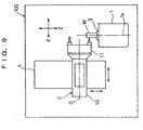
- the present invention may also be applicable to an automatic lathe comprising a tool rest main body that is freely movable on a lathe main body at least in an x-axis direction orthogonal to a main spindle axis, and a pair of coupling members capable of engaging with and disengaging from each other as a result of a relative movement in the x-axis direction taking place between the tool rest main body and a turret.
- the present invention can be embodied by a method of controlling an automatic lathe according to claim 2.
- the present invention can also be embodied by a method of controlling an automatic lathe comprising a lathe main body with a main spindle table mounted thereon, a tool rest main body freely movable on the lathe main body at least in a x-axis direction orthogonal to a main spindle axis, a turret mounted on the tool rest main body and capable of relatively moving in the x-axis direction against the tool rest main body and indexing around a predetermined rotary center, and a pair of coupling members installed on the tool rest main body and the turret, respectively, and capable of engaging with and disengaging from each other as a result of a relative movement in the x-axis direction taking place between the tool rest main body and the turret.
- the movement of the main spindle table in this case as well is adjusted in respect of direction and moving distance in such a way as to eliminate the relative movement between the turret and the main spindle table.
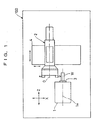
- the turret device 2 is mounted on a tool slide 4.
- the tool slide 4 is capable of moving the turret device 2 in a z-axis direction parallel with the main spindle axis 1a as well as in a x-axis direction orthogonal to the main spindle axis 1a by a driving device which is not shown here.
- the turret device 2 is moved in the z-axis direction as well as in the x-axis direction together with the tool slide 4, thereby cutting the workpiece W.
- the tool holder 16 for the rotary tool 14 has a tool rotary shaft 17 penetrating through the center of a holder body 16a and rotatable, while a tool chuck 18 for clamping the rotary tool 14 is installed at the tip of the tool rotary shaft 17. Further, a tool rotary gear 19 is installed at the base end portion of the tool rotary shaft 17.
- a base end portion 11a formed within a smaller diameter part of the turret 11 is fitted into the tool rest main body 10 in such a way as to be freely rotatable around the rotary center O as well as linearly movable along the rotary center O via a slide bearing 20 formed inside a hollow part 10a of the tool rest main body 10.
- a nut 25 is screwed into the ball screw 21, and fixedly attached to the base end portion 11a of the turret 11. Accordingly, rotation of the ball screw 21 is accompanied by a linear movement of the nut 25 along the rotary center O, causing the turret 11 to move linearly along the rotary center O (that is, in the z-axis direction) fixedly together with the nut 25.
- a screw feed mechanism 26 for causing the turret 11 to move linearly is made up of the ball screw 21 and the nut 25.
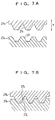
- the engagement and disengagement between the clutch pieces 31a, 31b have a reverse relationship to the engagement and disengagement between the couplings 27a, 27b. That is, when the turret 11 is moved to the right along the z-axis in Fig. 2, relative to the tool rest main body 10, the couplings 27a, 27b engage with each other while the clutch pieces 31a, 31b disengage from each other.
- the control part 40 has a timer function for measuring a length of time counted from a time when the driving command driving is sent out to the coupling motor driver 46 (S4), and if the clutch completion signal is not inputted therein even after the elapse of a predetermined length of time, the control part 40 decides it as abnormal state and stops the movement of the turret device 2 and displays an alarm (S 5).
Description
Claims (2)
- An automatic lathe comprising:a lathe main body (100) with a main spindle table (1) mounted thereon;a tool rest main body (10) freely movable on the lathe main body (100) at least in a z-axis direction parallel with or in an x-axis direction orthogonal to a main spindle axis (1a);a turret (11) mounted on the tool rest main body 10, and capable of relatively moving in the z-axis or the x-axis direction relative to the tool rest main body (10) and indexing around a rotary center parallel to the z-axis or the x-axis;a pair of coupling members (27) installed on the tool rest main body (10) and the turret (11), respectively, and capable of engaging with and disengaging from each other as a result of a relative movement in the z-axis or the x-axis direction taking place between the tool rest main body (10) and the turret (11); characterized bycontrol means for eliminating a relative movement between the turret (11) and the main spindle table (1) being adapted to course a move of the tool rest main body (10) or the main spindle table (1) in the opposite z-axis or the x-axis direction relative to the lathe main body (100), in synchronization with and comparating the relative movement in the z-axis or the x-axis direction taking place between the tool rest main body (10) and the turret (11).
- A method of controlling an automatic lathe comprising a lathe main body (100) with a main spindle table (1) mounted thereon, a tool rest main body (10) freely movable on the lathe main body (100) at least in a z-axis direction parallel with or an x-axis direction orthogonal to a main spindle axis (1a), a turret (11) mounted on the tool rest main body (10) and capable of relatively moving in the z-axis or the x-axis direction relative to the tool rest main body (10) and indexing around a rotary center parallel to the z-axis or the x-axis, and a pair of coupling members (27) installed on the tool rest main body (10) and the turret (11), respectively, and capable of engaging with and disengaging from each other as a result of a relative movement in the z-axis or the x-axis direction taking place between the tool rest main body (10) and the turret (11);
said method is characterized in that a relative movement between the turret and the main spindle table is eliminated by moving the tool rest main body or the main spindle table (1) in the opposite z-axis or the x-axis direction, relative to the lathe main body (100), in synchronization with and compensating the relative movement in the z-axis or the x-axis direction taking place between the tool rest main body (10) and the turret (11).
Applications Claiming Priority (1)
| Application Number | Priority Date | Filing Date | Title |
|---|---|---|---|
| PCT/JP1997/003028 WO1999011408A1 (en) | 1997-08-29 | 1997-08-29 | Automatic lathe and method of controlling same |
Publications (3)
| Publication Number | Publication Date |
|---|---|
| EP1048380A1 EP1048380A1 (en) | 2000-11-02 |
| EP1048380A4 EP1048380A4 (en) | 2000-11-02 |
| EP1048380B1 true EP1048380B1 (en) | 2001-12-05 |
Family
ID=14181047
Family Applications (2)
| Application Number | Title | Priority Date | Filing Date |
|---|---|---|---|
| EP97937846A Expired - Lifetime EP1048380B1 (en) | 1997-08-29 | 1997-08-29 | Automatic lathe and method of controlling same |
| EP98911229A Expired - Lifetime EP1053811B1 (en) | 1997-08-29 | 1998-04-07 | Automatic lathe and control method therefor |
Family Applications After (1)
| Application Number | Title | Priority Date | Filing Date |
|---|---|---|---|
| EP98911229A Expired - Lifetime EP1053811B1 (en) | 1997-08-29 | 1998-04-07 | Automatic lathe and control method therefor |
Country Status (7)
| Country | Link |
|---|---|
| US (2) | US6257109B1 (en) |
| EP (2) | EP1048380B1 (en) |
| JP (1) | JP4067134B2 (en) |
| KR (1) | KR100379934B1 (en) |
| DE (2) | DE69708934T2 (en) |
| TW (1) | TW391907B (en) |
| WO (2) | WO1999011408A1 (en) |
Families Citing this family (13)
| Publication number | Priority date | Publication date | Assignee | Title |
|---|---|---|---|---|
| US6609441B1 (en) * | 1996-12-13 | 2003-08-26 | Citizen Watch Co., Ltd. | Indexing device |
| JP3756143B2 (en) * | 2002-03-18 | 2006-03-15 | 株式会社ミヤノ | Machine tools and opposed spindle machine tools |
| DE102005009893B4 (en) * | 2005-03-01 | 2007-01-11 | Emag Holding Gmbh | Machine tool with at least one tool turret |
| US20090053000A1 (en) * | 2006-04-07 | 2009-02-26 | Miyano Steven S | Compact High Precision Multiple Spindle Computer Controlled Machine Tool |
| DE602007013900D1 (en) * | 2006-07-07 | 2011-05-26 | Kuraray Co | LAMINATE SHEET AND DISPLAY SHADE |
| JP2009125856A (en) * | 2007-11-22 | 2009-06-11 | Murata Mach Ltd | Machine tool, sensor module, and measuring method |
| JP5414221B2 (en) * | 2008-08-29 | 2014-02-12 | シチズンマシナリーミヤノ株式会社 | Turret tool post |
| CN103920900B (en) * | 2014-03-28 | 2017-01-18 | 浙江日发精密机械股份有限公司 | Vertical pneumatic-locking power turret |
| JP2016153149A (en) * | 2015-02-20 | 2016-08-25 | ファナック株式会社 | Machine tool having lathe tool holder mounting unit |
| EP3292929B1 (en) * | 2016-09-09 | 2022-11-16 | Sandvik Intellectual Property AB | Estimation of orientation of a cutting tool |
| EP3338921B1 (en) * | 2016-12-23 | 2019-08-07 | Kooyen Holding B.V. | Device for drilling holes in the axial and radial direction of a blade root of a wind turbine |
| TWI765644B (en) * | 2021-04-07 | 2022-05-21 | 鉅基科技股份有限公司 | Bidirectional output power turret and processing machine with bidirectional output power turret |
| CN113275903A (en) * | 2021-04-28 | 2021-08-20 | 高茂云 | Lathe clamping device with protection function |
Family Cites Families (31)
| Publication number | Priority date | Publication date | Assignee | Title |
|---|---|---|---|---|
| US3760472A (en) * | 1972-02-17 | 1973-09-25 | Kearney & Trecker Corp | Spindle change mechanism for a multiple spindle head machine |
| GB1411705A (en) * | 1972-06-10 | 1975-10-29 | Citizen Watch Co Ltd | Numerical control lathe of sliding headstock type |
| DE2239856C3 (en) * | 1972-08-12 | 1979-01-18 | Cri-Dan, Paris | Tool arrangement on a thread cutting machine |
| US4074177A (en) * | 1975-07-17 | 1978-02-14 | Giddings & Lewis, Inc. | Methods and apparatus for automatic movement of a member to precisely indexed positions despite signal drift or offset |
| US4090281A (en) * | 1976-11-19 | 1978-05-23 | Ameco Corporation | Machine tool with multiple tool turret |
| DE2737664A1 (en) | 1977-08-20 | 1979-02-22 | Index Werke Kg Hahn & Tessky | REVOLVER TURNING MACHINE |
| JPS55120943A (en) * | 1979-03-09 | 1980-09-17 | Brother Ind Ltd | Tool replacing device for machine tool |
| US4413539A (en) * | 1979-10-31 | 1983-11-08 | Citizen Watch Company Limited | Numerically controlled lathe |
| NL8100690A (en) * | 1981-02-12 | 1982-09-01 | Hembrug Gereedschapswerktuigen | TOOL CHANGER. |
| JPS6017929U (en) * | 1983-07-15 | 1985-02-06 | 株式会社 不二精機製造所 | Machine of machining center |
| IT1173463B (en) * | 1984-03-23 | 1987-06-24 | Andrea Spa D | MILLING HEAD AND BORING FOR MACHINE TOOL |
| EP0197172B1 (en) * | 1985-04-09 | 1988-07-27 | Wilhelm Hegenscheidt Gesellschaft mbH | Device to obtain broken chips during the machining of work pieces |
| JPS61260905A (en) * | 1985-05-13 | 1986-11-19 | Kamizaki Kokyu Koki Seisakusho Kk | Machine tool |
| DE3734687C2 (en) * | 1987-10-14 | 1994-11-17 | Index Werke Kg Hahn & Tessky | Method for loading and unloading the main spindle of a lathe and lathe for performing this method |
| DE3990008C1 (en) * | 1988-01-09 | 1990-10-25 | Index-Werke Kg Hahn & Tessky, 7300 Esslingen, De | |
| JPH06104293B2 (en) * | 1989-01-30 | 1994-12-21 | 豊田工機株式会社 | Non-roundness control device |
| JPH06104291B2 (en) * | 1989-04-25 | 1994-12-21 | オ−クマ株式会社 | Turret turning control system and its equipment for numerically controlled lathe |
| JPH0319747A (en) * | 1989-06-14 | 1991-01-28 | Yamazaki Mazak Corp | Tool exchanger for numerically controlled lathe |
| JPH0739069B2 (en) * | 1989-09-04 | 1995-05-01 | ブラザー工業株式会社 | Numerical control machine tool |
| US5097587A (en) * | 1989-09-04 | 1992-03-24 | Brother Kogyo Kabushiki Kaisha | Numerically controlled machine tool with automatic tool exchange device and indexing device |
| JP2556382B2 (en) * | 1989-10-20 | 1996-11-20 | 日立精機株式会社 | Indexing turret for machine tools |
| US5315526A (en) * | 1989-12-07 | 1994-05-24 | Okuma Corporation | Numerically controlled lathe |
| US5127140A (en) * | 1989-12-18 | 1992-07-07 | Hitachi Seiki Co., Ltd. | Numerically-controlled lathe, numerically-controlled device therefor and processing procedure thereby |
| US5084951A (en) * | 1990-11-30 | 1992-02-04 | Imta | Multi-axis tool positioner |
| JPH0596449A (en) * | 1991-10-03 | 1993-04-20 | Murata Mach Ltd | Indexing method for turret lathe intended for rotary tool |
| JPH05200601A (en) * | 1992-01-24 | 1993-08-10 | Takizawa Tekkosho:Kk | Machine tool |
| JP3136745B2 (en) | 1992-03-27 | 2001-02-19 | 株式会社島津製作所 | Particle size distribution analyzer |
| JP3259371B2 (en) * | 1992-11-17 | 2002-02-25 | 三菱電機株式会社 | Work holding method and device for machine tool |
| JPH0739069A (en) * | 1993-07-16 | 1995-02-07 | Toshiba Corp | Spot network power receiving and distributing apparatus |
| JP2948063B2 (en) * | 1993-07-26 | 1999-09-13 | オークマ株式会社 | Drilling center with work reversing mechanism |
| US5842392A (en) * | 1996-12-13 | 1998-12-01 | Citizen Watch Co., Ltd. | Indexing device and method of driving the same |
-
1997
- 1997-08-29 EP EP97937846A patent/EP1048380B1/en not_active Expired - Lifetime
- 1997-08-29 WO PCT/JP1997/003028 patent/WO1999011408A1/en active IP Right Grant
- 1997-08-29 US US09/486,378 patent/US6257109B1/en not_active Ceased
- 1997-08-29 DE DE69708934T patent/DE69708934T2/en not_active Expired - Lifetime
- 1997-08-29 US US10/139,222 patent/USRE38571E1/en not_active Expired - Lifetime
- 1997-09-06 TW TW086112880A patent/TW391907B/en not_active IP Right Cessation
-
1998
- 1998-04-07 EP EP98911229A patent/EP1053811B1/en not_active Expired - Lifetime
- 1998-04-07 WO PCT/JP1998/001594 patent/WO1999011409A1/en active IP Right Grant
- 1998-04-07 KR KR10-2000-7002074A patent/KR100379934B1/en not_active IP Right Cessation
- 1998-04-07 JP JP51656499A patent/JP4067134B2/en not_active Expired - Fee Related
- 1998-04-07 DE DE69824636T patent/DE69824636T2/en not_active Expired - Lifetime
Also Published As
| Publication number | Publication date |
|---|---|
| KR100379934B1 (en) | 2003-04-11 |
| DE69708934T2 (en) | 2002-06-20 |
| EP1053811A1 (en) | 2000-11-22 |
| JP4067134B2 (en) | 2008-03-26 |
| EP1053811A4 (en) | 2000-11-22 |
| WO1999011409A1 (en) | 1999-03-11 |
| US6257109B1 (en) | 2001-07-10 |
| TW391907B (en) | 2000-06-01 |
| EP1053811B1 (en) | 2004-06-16 |
| DE69824636D1 (en) | 2004-07-22 |
| DE69824636T2 (en) | 2005-06-09 |
| KR20010023431A (en) | 2001-03-26 |
| DE69708934D1 (en) | 2002-01-17 |
| WO1999011408A1 (en) | 1999-03-11 |
| USRE38571E1 (en) | 2004-08-31 |
| EP1048380A1 (en) | 2000-11-02 |
| EP1048380A4 (en) | 2000-11-02 |
Similar Documents
| Publication | Publication Date | Title |
|---|---|---|
| EP0890411B1 (en) | Indexing apparatus and method for driving the same for indexing the same | |
| EP1048380B1 (en) | Automatic lathe and method of controlling same | |
| EP0890401B1 (en) | Turret tool rest | |
| EP0925862A1 (en) | Electric chuck for machine tool and method of opening or closing gripping pawl of same | |
| US6609441B1 (en) | Indexing device | |
| US6257111B1 (en) | Automatic lathe and control method therefor | |
| US8967925B2 (en) | Machine tool | |
| EP0890412B1 (en) | Indexing apparatus and method for controlling the indexing apparatus | |
| KR100401474B1 (en) | Turret tool rest | |
| EP1122011B1 (en) | Capstan rest | |
| KR100317682B1 (en) | Automatic lathe and method of controlling same | |
| CN114158265A (en) | Tool holder and machining method | |
| JP2557002Y2 (en) | Tool post of compound NC lathe | |
| JPH08257863A (en) | Driving gear performing turning and turn axial line direction moving by single drive source | |
| JP2001150204A (en) | Tail stock driving gear in nc machine tool |
Legal Events
| Date | Code | Title | Description |
|---|---|---|---|
| PUAI | Public reference made under article 153(3) epc to a published international application that has entered the european phase |
Free format text: ORIGINAL CODE: 0009012 |
|
| 17P | Request for examination filed |
Effective date: 20000229 |
|
| A4 | Supplementary search report drawn up and despatched |
Effective date: 20000419 |
|
| AK | Designated contracting states |
Kind code of ref document: A4 Designated state(s): CH DE FR GB IT LI Kind code of ref document: A1 Designated state(s): CH DE FR GB IT LI |
|
| 17Q | First examination report despatched |
Effective date: 20001228 |
|
| GRAG | Despatch of communication of intention to grant |
Free format text: ORIGINAL CODE: EPIDOS AGRA |
|
| GRAG | Despatch of communication of intention to grant |
Free format text: ORIGINAL CODE: EPIDOS AGRA |
|
| GRAH | Despatch of communication of intention to grant a patent |
Free format text: ORIGINAL CODE: EPIDOS IGRA |
|
| GRAH | Despatch of communication of intention to grant a patent |
Free format text: ORIGINAL CODE: EPIDOS IGRA |
|
| GRAA | (expected) grant |
Free format text: ORIGINAL CODE: 0009210 |
|
| RAP1 | Party data changed (applicant data changed or rights of an application transferred) |
Owner name: CITIZEN WATCH CO. LTD. |
|
| AK | Designated contracting states |
Kind code of ref document: B1 Designated state(s): CH DE FR GB IT LI |
|
| REG | Reference to a national code |
Ref country code: CH Ref legal event code: EP |
|
| REG | Reference to a national code |
Ref country code: GB Ref legal event code: IF02 |
|
| REF | Corresponds to: |
Ref document number: 69708934 Country of ref document: DE Date of ref document: 20020117 |
|
| ET | Fr: translation filed | ||
| REG | Reference to a national code |
Ref country code: CH Ref legal event code: NV Representative=s name: R. A. EGLI & CO. PATENTANWAELTE |
|
| PLBE | No opposition filed within time limit |
Free format text: ORIGINAL CODE: 0009261 |
|
| STAA | Information on the status of an ep patent application or granted ep patent |
Free format text: STATUS: NO OPPOSITION FILED WITHIN TIME LIMIT |
|
| 26N | No opposition filed | ||
| REG | Reference to a national code |
Ref country code: CH Ref legal event code: PFA Owner name: CITIZEN HOLDINGS CO., LTD. Free format text: CITIZEN WATCH CO. LTD.#1-12, TANASHICHO 6-CHOME, NISHITOKYO-SHI#TOKYO 188-8511 (JP) -TRANSFER TO- CITIZEN HOLDINGS CO., LTD.#1-12, TANASHICHO 6-CHOME#NISHITOKYO-SHI, TOKYO 188-8511 (JP) |
|
| REG | Reference to a national code |
Ref country code: FR Ref legal event code: CD |
|
| PGFP | Annual fee paid to national office [announced via postgrant information from national office to epo] |
Ref country code: FR Payment date: 20100824 Year of fee payment: 14 |
|
| PGFP | Annual fee paid to national office [announced via postgrant information from national office to epo] |
Ref country code: GB Payment date: 20100825 Year of fee payment: 14 |
|
| PGFP | Annual fee paid to national office [announced via postgrant information from national office to epo] |
Ref country code: CH Payment date: 20110812 Year of fee payment: 15 |
|
| PGFP | Annual fee paid to national office [announced via postgrant information from national office to epo] |
Ref country code: DE Payment date: 20110824 Year of fee payment: 15 |
|
| PGFP | Annual fee paid to national office [announced via postgrant information from national office to epo] |
Ref country code: IT Payment date: 20110823 Year of fee payment: 15 |
|
| GBPC | Gb: european patent ceased through non-payment of renewal fee |
Effective date: 20110829 |
|
| REG | Reference to a national code |
Ref country code: FR Ref legal event code: ST Effective date: 20120430 |
|
| PG25 | Lapsed in a contracting state [announced via postgrant information from national office to epo] |
Ref country code: GB Free format text: LAPSE BECAUSE OF NON-PAYMENT OF DUE FEES Effective date: 20110829 Ref country code: FR Free format text: LAPSE BECAUSE OF NON-PAYMENT OF DUE FEES Effective date: 20110831 |
|
| REG | Reference to a national code |
Ref country code: CH Ref legal event code: PL |
|
| PG25 | Lapsed in a contracting state [announced via postgrant information from national office to epo] |
Ref country code: CH Free format text: LAPSE BECAUSE OF NON-PAYMENT OF DUE FEES Effective date: 20120831 Ref country code: LI Free format text: LAPSE BECAUSE OF NON-PAYMENT OF DUE FEES Effective date: 20120831 |
|
| PG25 | Lapsed in a contracting state [announced via postgrant information from national office to epo] |
Ref country code: IT Free format text: LAPSE BECAUSE OF NON-PAYMENT OF DUE FEES Effective date: 20120829 |
|
| PG25 | Lapsed in a contracting state [announced via postgrant information from national office to epo] |
Ref country code: DE Free format text: LAPSE BECAUSE OF NON-PAYMENT OF DUE FEES Effective date: 20130301 |
|
| REG | Reference to a national code |
Ref country code: DE Ref legal event code: R119 Ref document number: 69708934 Country of ref document: DE Effective date: 20130301 |