EP0890333B1 - Spit - Google Patents
Spit Download PDFInfo
- Publication number
- EP0890333B1 EP0890333B1 EP98300871A EP98300871A EP0890333B1 EP 0890333 B1 EP0890333 B1 EP 0890333B1 EP 98300871 A EP98300871 A EP 98300871A EP 98300871 A EP98300871 A EP 98300871A EP 0890333 B1 EP0890333 B1 EP 0890333B1
- Authority
- EP
- European Patent Office
- Prior art keywords
- skewer
- support member
- spit
- coupled
- food
- Prior art date
- Legal status (The legal status is an assumption and is not a legal conclusion. Google has not performed a legal analysis and makes no representation as to the accuracy of the status listed.)
- Expired - Lifetime
Links
Images




Classifications
-
- A—HUMAN NECESSITIES
- A47—FURNITURE; DOMESTIC ARTICLES OR APPLIANCES; COFFEE MILLS; SPICE MILLS; SUCTION CLEANERS IN GENERAL
- A47J—KITCHEN EQUIPMENT; COFFEE MILLS; SPICE MILLS; APPARATUS FOR MAKING BEVERAGES
- A47J37/00—Baking; Roasting; Grilling; Frying
- A47J37/04—Roasting apparatus with movably-mounted food supports or with movable heating implements; Spits
- A47J37/043—Roasting apparatus with movably-mounted food supports or with movable heating implements; Spits with food supports rotating about a vertical axis
-
- A—HUMAN NECESSITIES
- A47—FURNITURE; DOMESTIC ARTICLES OR APPLIANCES; COFFEE MILLS; SPICE MILLS; SUCTION CLEANERS IN GENERAL
- A47J—KITCHEN EQUIPMENT; COFFEE MILLS; SPICE MILLS; APPARATUS FOR MAKING BEVERAGES
- A47J43/00—Implements for preparing or holding food, not provided for in other groups of this subclass
- A47J43/18—Holding or clamping devices for supporting fowl, venison, or other meat, or vegetables, during cooking or during subsequent cutting
-
- H—ELECTRICITY
- H05—ELECTRIC TECHNIQUES NOT OTHERWISE PROVIDED FOR
- H05B—ELECTRIC HEATING; ELECTRIC LIGHT SOURCES NOT OTHERWISE PROVIDED FOR; CIRCUIT ARRANGEMENTS FOR ELECTRIC LIGHT SOURCES, IN GENERAL
- H05B6/00—Heating by electric, magnetic or electromagnetic fields
- H05B6/64—Heating using microwaves
- H05B6/6408—Supports or covers specially adapted for use in microwave heating apparatus
-
- Y—GENERAL TAGGING OF NEW TECHNOLOGICAL DEVELOPMENTS; GENERAL TAGGING OF CROSS-SECTIONAL TECHNOLOGIES SPANNING OVER SEVERAL SECTIONS OF THE IPC; TECHNICAL SUBJECTS COVERED BY FORMER USPC CROSS-REFERENCE ART COLLECTIONS [XRACs] AND DIGESTS
- Y10—TECHNICAL SUBJECTS COVERED BY FORMER USPC
- Y10S—TECHNICAL SUBJECTS COVERED BY FORMER USPC CROSS-REFERENCE ART COLLECTIONS [XRACs] AND DIGESTS
- Y10S99/00—Foods and beverages: apparatus
- Y10S99/14—Induction heating
Definitions
- the present invention relates to a spit comprising a skewer and a support member for supporting the skewer and coupling means provided on the support member and the skewer to enable separation of the skewer from the support member and to enable it to be coupled to the support member in an operational configuration in which the skewer is substantially vertical when the spit is resting on the support member, and a non-operational configuration in which the spit is significantly flatter than when the skewer is coupled to the support member in its operational configuration.
- FIG. 1 A sectional view of a conventional microwave oven is illustrated in Figure 1 and is an appliance which cooks food using microwave energy generated by a magnetron.
- a conventional microwave oven includes a housing 1 surrounding a cooking chamber 2 for cooking food therein and a component compartment 3 in which microwave energy and heat from a magnetron 8 and a heater 7 is respectively generated and directed into the cooking chamber 2.
- the cooking chamber 2 and component compartment 3 are separated from each other by an inner panel 4.
- the tray 5 is rotated by a motor 6 disposed under tray 5.
- a high voltage transformer (not shown) is disposed in the component compartment 3, and a guide tube 9 for guiding and dissipating the microwave energy in the cooking chamber is provided between the magnetron 8 and the cooking chamber 2.
- microwave energy is generated by the magnetron 8 and is guided through guide tube 9 into the cooking chamber 2.
- Food in the cooking chamber 2 is also heated by heat supplied by the heater 7. Whilst cooking is in progress, the driving motor 6 rotates the tray 5 at a low constant speed to disperse the microwave energy throughout the food and ensure that it cooks uniformly.
- the conventional microwave oven include various supplementary devices depending on the type of the food to be cooked.
- a roasting spit 10 is often supplied to enable, for example, a chicken to be roasted.
- a typical roasting spit 10 is shown in Figure 2 and includes a ring-shaped support member 11 and a skewer 12.
- Support member 11 is placed on the tray 5 and the skewer 12, which is formed from one end of support member 11, is bent so that the skewer 12 extends upwardly from the tray 5 in the cooking chamber 2 to enable food to be roasted to be spiked by the skewer and held thereby.
- the tip of the skewer 12 has a sharp point to enable it to pierce food easily.
- the food is roasted as the tray 5, on which the roasting spit 10 is placed, rotates during operation of the microwave oven.
- a conventional roasting spit 10 of the type described above has several disadvantages. As it is made by bending a thin, long single rod-shaped member, skewer 12 extends upwardly and its sharp unprotected tip creates a safety hazard. Furthermore, its shape means that it is difficult and expensive to package securely for distribution to customers and to store when not in use.
- a spit in accordance with the present invention is characterised in that the support member comprises an arcuate portion extending for greater than 180 degrees, a first terminal portion extending radially inwardly from one end of the arcuate portion, and a second terminal portion extending radially inwardly from the other end of the arcuate portion, and then axially with respect to the arcuate portion.
- coupling means are provided on the support member and the skewer.
- the coupling means enables the skewer to be coupled to the support member in operational and non-operational configurations.
- the spit is significantly flatter than when the skewer is coupled to the support member in its operational configuration.
- the coupling means may conveniently comprise corresponding male and female screw threads on the support member and skewer or, alternatively, the coupling means may comprise a push-fit coupling.
- a further disadvantage with a conventional roasting spit of the type described above is that food placed on the skewer to be roasted tends to slide down the skewer during cooking.
- roasting spit which is characterised by means formed integrally with the skewer to prevent food from sliding down the skewer.
- the means to prevent food from sliding down the skewer comprises a kink in the skewer.
- roasting spit according to the present invention is described specifically with reference to a spit for use in a microwave oven. However, it will be appreciated that the spit could also be employed in other cooking appliances.
- a roasting spit 100 is illustrated in Figures 3 and 4 and includes a ring-shaped support member 120 and skewer 140.
- Support member 120 is placed on a tray 5 and the skewer 140 is releasably coupled to the support member 120.
- a horizontal end portion 122 of the support member 120 resting in contact with the tray 5 is bent radially inwardly toward the centre of the tray 5 whilst the other vertical end portion 124 extends upwardly from the tray 5.
- Both the end portions 122,124 terminate in male screw threads 122a and 124a respectively.
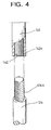
- the skewer 140 is provided with a threaded coupling hole 142 corresponding to the screw threads 122a,124a on the end portion 122 and vertical portion 124 respectively, as can be seen more clearly in Figure 4.
- the skewer 140 can be coupled to the vertical end portion 124 of support member 120 when in use, and coupled to the horizontal end portion 122 of the support member 120 when not being used, to enable it to be kept safely.
- the skewer 140 and the support member 120 for supporting the skewer 140 on the tray 5 are formed separately from each other. Therefore, when the roasting spit 100 is not being used the skewer 140 can be coupled to the horizontal end portion 122 for storage purposes. When the skewer 140 is located in this position, it does not protrude upwardly thereby preventing possible injury to a user or other person handling the spit 100. In addition, when the skewer 140 is coupled to the horizontal end portion 122, the roasting spit takes up much less space and this results in it being easier and cheaper to package for transportation as well as greatly reducing the package size.
- the roasting spit according to the second embodiment of the present invention shown in Figure 5 is similar to roasting spit 100 according to the first embodiment.
- the horizontal end portion 122 and vertical end portion 124 terminate in a narrowed cylindrical portion having a longitudinal slot 124b therein.
- the slot 124b enables the horizontal end portion 122 and vertical end portion 124 to be push fitted into the coupling hole 142 in the skewer which does not require an internal thread.
- the slot 124b allows the cylindrical portion to deform slightly to accommodate small dimensional differences between the diameter of the coupling hole 142 and the diameter of the cylindrical portion.
- roasting spit according to the second embodiment of the present invention described above provides not only the same advantages and effect as the roasting spit according to the first embodiment but also a further advantage that the horizontal and vertical end portions 122 and 124 of support member 120 can be coupled to the skewer 140 more easily and quickly.
- a third embodiment of the present invention is illustrated in Figure 6 and has a similar construction to the first embodiment shown in Figures 3 and 4.
- the roasting spit 100 further includes a kink or knot 146 in the skewer 140 to prevent the food being roasted from slipping down the skewer 140 during cooking.
- Figure 7 is similar to that of Figure 6 except that the horizontal and vertical portions 122,124 of the support member 120 are coupled by the arrangement described with reference to the second embodiment.
- the food to be roasted is prevented from sliding down the skewer 140 by the holding knot as shown in Figure 8.
- the third and the fourth embodiments provides an additional and distinct advantage from those described with reference to the first and second embodiments as the food to be roasted is prevented from slipping down the skewer 140 during cooking.
Landscapes
- Engineering & Computer Science (AREA)
- Food Science & Technology (AREA)
- Mechanical Engineering (AREA)
- Physics & Mathematics (AREA)
- Electromagnetism (AREA)
- Baking, Grill, Roasting (AREA)
- Cookers (AREA)
- Electric Ovens (AREA)
- Signal Processing For Digital Recording And Reproducing (AREA)
Description
- The present invention relates to a spit comprising a skewer and a support member for supporting the skewer and coupling means provided on the support member and the skewer to enable separation of the skewer from the support member and to enable it to be coupled to the support member in an operational configuration in which the skewer is substantially vertical when the spit is resting on the support member, and a non-operational configuration in which the spit is significantly flatter than when the skewer is coupled to the support member in its operational configuration. The above features are disclosed in document AU562277.
- A sectional view of a conventional microwave oven is illustrated in Figure 1 and is an appliance which cooks food using microwave energy generated by a magnetron.
- A conventional microwave oven includes a housing 1 surrounding a
cooking chamber 2 for cooking food therein and acomponent compartment 3 in which microwave energy and heat from amagnetron 8 and aheater 7 is respectively generated and directed into thecooking chamber 2. Thecooking chamber 2 andcomponent compartment 3 are separated from each other by an inner panel 4. - A
tray 5, on which a food container is placed, is disposed on the lower surface of thecooking chamber 2 and theheater 7 is disposed at the top ofcooking chamber 2. Thetray 5 is rotated by amotor 6 disposed undertray 5. - A high voltage transformer (not shown) is disposed in the
component compartment 3, and aguide tube 9 for guiding and dissipating the microwave energy in the cooking chamber is provided between themagnetron 8 and thecooking chamber 2. - When the conventional microwave oven of the type described above is used, microwave energy is generated by the
magnetron 8 and is guided throughguide tube 9 into thecooking chamber 2. Food in thecooking chamber 2 is also heated by heat supplied by theheater 7. Whilst cooking is in progress, the drivingmotor 6 rotates thetray 5 at a low constant speed to disperse the microwave energy throughout the food and ensure that it cooks uniformly. - The conventional microwave oven include various supplementary devices depending on the type of the food to be cooked. For example, a
roasting spit 10 is often supplied to enable, for example, a chicken to be roasted. - A
typical roasting spit 10 is shown in Figure 2 and includes a ring-shaped support member 11 and askewer 12.Support member 11 is placed on thetray 5 and theskewer 12, which is formed from one end ofsupport member 11, is bent so that theskewer 12 extends upwardly from thetray 5 in thecooking chamber 2 to enable food to be roasted to be spiked by the skewer and held thereby. The tip of theskewer 12 has a sharp point to enable it to pierce food easily. - The food is roasted as the
tray 5, on which theroasting spit 10 is placed, rotates during operation of the microwave oven. - A
conventional roasting spit 10 of the type described above has several disadvantages. As it is made by bending a thin, long single rod-shaped member,skewer 12 extends upwardly and its sharp unprotected tip creates a safety hazard. Furthermore, its shape means that it is difficult and expensive to package securely for distribution to customers and to store when not in use. - It is an object of the present invention to overcome or substantially alleviate the aforementioned disadvantages with a conventional roasting spit.
- A spit in accordance with the present invention is characterised in that the support member comprises an arcuate portion extending for greater than 180 degrees, a first terminal portion extending radially inwardly from one end of the arcuate portion, and a second terminal portion extending radially inwardly from the other end of the arcuate portion, and then axially with respect to the arcuate portion.
- In a preferred embodiment, coupling means are provided on the support member and the skewer.
- Preferably, the coupling means enables the skewer to be coupled to the support member in operational and non-operational configurations.
- Preferably, when the skewer is coupled to the support member in its non-operational configuration, the spit is significantly flatter than when the skewer is coupled to the support member in its operational configuration.
- The coupling means may conveniently comprise corresponding male and female screw threads on the support member and skewer or, alternatively, the coupling means may comprise a push-fit coupling.
- A further disadvantage with a conventional roasting spit of the type described above is that food placed on the skewer to be roasted tends to slide down the skewer during cooking.
- The aforementioned problem with a conventional roasting spit is overcome or substantially alleviated by providing a roasting spit which is characterised by means formed integrally with the skewer to prevent food from sliding down the skewer.
- Preferably, the means to prevent food from sliding down the skewer comprises a kink in the skewer.
- The roasting spit according to the present invention is described specifically with reference to a spit for use in a microwave oven. However, it will be appreciated that the spit could also be employed in other cooking appliances.
- Embodiments of the present invention will now be described, by way of example only, with reference to the accompanying drawings, in which:
- Figure 1 is a schematic sectional view showing the inner construction of a conventional microwave oven;
- Figure 2 is a perspective view showing a conventional roasting spit;
- Figure 3 is an exploded perspective view showing a roasting spit according to a first embodiment of the present invention;
- Figure 4 is an enlarged exploded perspective view of the portion marked 'A' in Figure 3;
- Figure 5 is an enlarged exploded perspective view showing a coupling portion according to a second embodiment of the present invention;
- Figure 6 is an exploded perspective view showing a roasting spit according to a third embodiment of the present invention;
- Figure 7 is an enlarged exploded perspective view showing a roasting spit according to a fourth embodiment of the present invention; and
- Figure 8 is a view showing a preferred roasting spit inserted into a roast and disposed on a tray.
-
- A
roasting spit 100 according to the first embodiment of the present invention is illustrated in Figures 3 and 4 and includes a ring-shaped support member 120 andskewer 140.Support member 120 is placed on atray 5 and theskewer 140 is releasably coupled to thesupport member 120. - A
horizontal end portion 122 of thesupport member 120 resting in contact with thetray 5 is bent radially inwardly toward the centre of thetray 5 whilst the othervertical end portion 124 extends upwardly from thetray 5. Both the end portions 122,124 terminate inmale screw threads skewer 140 is provided with a threadedcoupling hole 142 corresponding to thescrew threads end portion 122 andvertical portion 124 respectively, as can be seen more clearly in Figure 4. - According to the first embodiment of the present invention as described above, the
skewer 140 can be coupled to thevertical end portion 124 ofsupport member 120 when in use, and coupled to thehorizontal end portion 122 of thesupport member 120 when not being used, to enable it to be kept safely. - According to the first embodiment of the invention, the
skewer 140 and thesupport member 120 for supporting theskewer 140 on thetray 5 are formed separately from each other. Therefore, when theroasting spit 100 is not being used theskewer 140 can be coupled to thehorizontal end portion 122 for storage purposes. When theskewer 140 is located in this position, it does not protrude upwardly thereby preventing possible injury to a user or other person handling thespit 100. In addition, when theskewer 140 is coupled to thehorizontal end portion 122, the roasting spit takes up much less space and this results in it being easier and cheaper to package for transportation as well as greatly reducing the package size. - An alternative method of coupling the
skewer 140 to thesupport member 120 is illustrated in Figure 5. - The roasting spit according to the second embodiment of the present invention shown in Figure 5 is similar to roasting
spit 100 according to the first embodiment. However, instead ofscrew thread horizontal end portion 122 andvertical end portion 124 terminate in a narrowed cylindrical portion having alongitudinal slot 124b therein. Theslot 124b enables thehorizontal end portion 122 andvertical end portion 124 to be push fitted into thecoupling hole 142 in the skewer which does not require an internal thread. Theslot 124b allows the cylindrical portion to deform slightly to accommodate small dimensional differences between the diameter of thecoupling hole 142 and the diameter of the cylindrical portion. - The roasting spit according to the second embodiment of the present invention described above provides not only the same advantages and effect as the roasting spit according to the first embodiment but also a further advantage that the horizontal and
vertical end portions support member 120 can be coupled to theskewer 140 more easily and quickly. - A third embodiment of the present invention is illustrated in Figure 6 and has a similar construction to the first embodiment shown in Figures 3 and 4. In the third embodiment, the
roasting spit 100 further includes a kink orknot 146 in theskewer 140 to prevent the food being roasted from slipping down theskewer 140 during cooking. - The embodiment of Figure 7 is similar to that of Figure 6 except that the horizontal and vertical portions 122,124 of the
support member 120 are coupled by the arrangement described with reference to the second embodiment. - As described above, the food to be roasted is prevented from sliding down the
skewer 140 by the holding knot as shown in Figure 8. - The third and the fourth embodiments provides an additional and distinct advantage from those described with reference to the first and second embodiments as the food to be roasted is prevented from slipping down the
skewer 140 during cooking. - While the present invention has been particularly shown and described with reference to the foregoing embodiments, it will be understood by those skilled in the art that various changes in form and detail may be effected therein without departing from the scope of the invention as defined by the appended claims.
Claims (6)
- A spit comprising a skewer (140), a support member (120) for supporting the skewer (140) and coupling means (122a,124a,142) provided on the support member (120) and the skewer (140) to enable separation of the skewer (140) from the support member (120), and to enable it to be coupled to the support member (120) in an operational configuration in which the skewer (140) is substantially vertical when the spit is resting on the support member, and a non-operational configuration in which the spit is significantly flatter than when the skewer is coupled to the support member in its operational configuration, characterised in that the support member (120) comprises an arcuate portion extending for greater than 180 degrees, a first terminal portion (122) extending radially inwardly from one end of the arcuate portion, and a second terminal portion (124) extending radially inwardly from the other end of the arcuate portion, and then axially with respect to the arcuate portion.
- A spit according to claim 1, wherein the coupling means (122a,124a,142) comprises corresponding male and female screw threads on the support member (120) and skewer (140).
- A spit according to claim 1 or claim 2, wherein the coupling means (122a,124a,142) comprises a push-fit coupling.
- A spit according to any preceding claim wherein the skewer (140) includes means (146) to prevent food from sliding down the skewer (140).
- A spit according to claim 4, wherein said means (146) comprises a kink in the skewer.
- A microwave oven comprising a cooking chamber in which a spit according to any preceding claim is disposed.
Applications Claiming Priority (2)
| Application Number | Priority Date | Filing Date | Title |
|---|---|---|---|
| KR9732411 | 1997-07-12 | ||
| KR1019970032411A KR19990009863A (en) | 1997-07-12 | 1997-07-12 | Microwave Grilled Meat Spit |
Publications (2)
| Publication Number | Publication Date |
|---|---|
| EP0890333A1 EP0890333A1 (en) | 1999-01-13 |
| EP0890333B1 true EP0890333B1 (en) | 2003-05-02 |
Family
ID=19514257
Family Applications (1)
| Application Number | Title | Priority Date | Filing Date |
|---|---|---|---|
| EP98300871A Expired - Lifetime EP0890333B1 (en) | 1997-07-12 | 1998-02-05 | Spit |
Country Status (8)
| Country | Link |
|---|---|
| US (1) | US5981926A (en) |
| EP (1) | EP0890333B1 (en) |
| JP (1) | JP2837156B1 (en) |
| KR (1) | KR19990009863A (en) |
| CN (2) | CN1102843C (en) |
| DE (1) | DE69813956T2 (en) |
| MY (1) | MY118816A (en) |
| RU (1) | RU2140041C1 (en) |
Cited By (1)
| Publication number | Priority date | Publication date | Assignee | Title |
|---|---|---|---|---|
| WO2008144837A1 (en) * | 2007-06-01 | 2008-12-04 | Bob Fairclough | Cooking aid |
Families Citing this family (23)
| Publication number | Priority date | Publication date | Assignee | Title |
|---|---|---|---|---|
| US20010039884A1 (en) | 1997-07-07 | 2001-11-15 | Alan L. Backus | Simplified device to quickly cook food |
| US6874408B2 (en) | 1998-12-21 | 2005-04-05 | Advantage Partners Ip, Llc | Rotisserie cooker |
| US6450087B2 (en) | 1998-12-21 | 2002-09-17 | Alan L. Backus | Rotisserie oven having a shaped food basket |
| US7325484B1 (en) | 1998-12-21 | 2008-02-05 | Ronco Acquisition Corporation | Enclosed rotisserie with added convenience |
| US6173645B1 (en) | 1999-11-09 | 2001-01-16 | Alan L. Backus | Convenient food supporting vessel for use on a rotisserie cooking spit |
| US6988445B1 (en) | 1998-12-21 | 2006-01-24 | Advantage Partners, Llc | Enclosed rotisserie with added convenience |
| US6170390B1 (en) * | 1998-12-21 | 2001-01-09 | Alan L. Backus | Enclosed rotisserie with added convenience |
| US7021204B2 (en) | 1998-12-21 | 2006-04-04 | Backus Alan L | Enclosed rotisserie with detachable electronic components |
| US6658991B2 (en) | 1998-12-21 | 2003-12-09 | Alan L. Backus | Barbeque grill spit assembly |
| US6568316B1 (en) | 2001-12-05 | 2003-05-27 | Alan L. Backus | Rotisserie spit attachment |
| US6965095B1 (en) | 2004-09-20 | 2005-11-15 | Ronco Inventions, Llc | Rotisserie oven having horizontally and vertically oriented cooking elements |
| US20060266227A1 (en) * | 2005-05-25 | 2006-11-30 | Britt Gary E | Cooking device |
| USD532659S1 (en) | 2005-05-25 | 2006-11-28 | Gary Britt | Cooking device |
| USD545903S1 (en) * | 2006-07-10 | 2007-07-03 | Mark Ross | Paper tack |
| CN101777352B (en) * | 2009-12-11 | 2011-08-24 | 沈阳理工大学 | Single-track eight-digit magnetic information processing method |
| CN101763861B (en) * | 2009-12-11 | 2011-08-24 | 沈阳理工大学 | Single-track four-bit digital magnetic information processing method |
| JP2013076502A (en) * | 2011-09-30 | 2013-04-25 | Panasonic Corp | High-frequency heating device with electrothermic heating device |
| US20150374176A1 (en) * | 2014-06-30 | 2015-12-31 | James Hamilton | Carving pin for carving a cooked roast, and methods and systems |
| US9907593B2 (en) | 2014-08-05 | 2018-03-06 | Woven Orthopedic Technologies, Llc | Woven retention devices, systems and methods |
| WO2017024277A1 (en) | 2015-08-05 | 2017-02-09 | Woven Orthopedic Technologies, Llc | Tapping devices, systems and methods for use in bone tissue |
| US10314431B2 (en) * | 2016-10-27 | 2019-06-11 | Shawn Choy | Infusion cooking assembly |
| US11395681B2 (en) | 2016-12-09 | 2022-07-26 | Woven Orthopedic Technologies, Llc | Retention devices, lattices and related systems and methods |
| US10674864B2 (en) * | 2017-07-14 | 2020-06-09 | Slavisa Trtic | Cooking device for improved heating |
Family Cites Families (18)
| Publication number | Priority date | Publication date | Assignee | Title |
|---|---|---|---|---|
| GB592641A (en) * | 1945-05-21 | 1947-09-24 | Abraham Alexander Crompton | Improvements in devices for supporting meat or the like in baking tins |
| US1308253A (en) * | 1919-07-01 | Seeb-cobn holbek | ||
| US2458239A (en) * | 1946-10-17 | 1949-01-04 | Edward T Bartlett | Support for fowl or the like |
| US2584295A (en) * | 1949-09-17 | 1952-02-05 | Donald L Sanzenbacher | Culinary accessory |
| FR1151237A (en) * | 1956-06-06 | 1958-01-27 | Household device for cutting and presenting poultry | |
| DE1679266C3 (en) * | 1967-03-10 | 1981-04-09 | Vogt, Hans, Dr.H.C., 8391 Erlau | Device for cooking poultry |
| US3713378A (en) * | 1971-02-18 | 1973-01-30 | Cobb J | Baster and tenderizer |
| US4481874A (en) * | 1983-05-06 | 1984-11-13 | Neat Products, Inc. | Wire meat support |
| BE901209A (en) * | 1984-12-05 | 1985-03-29 | Zweegers Bernardus P A | Pan for preparing meat or poultry in oven - has fixed bush for inserting end of member, holding meat over water |
| AU562277B2 (en) * | 1985-09-13 | 1987-06-04 | George Jackson Hamlyn | Chicken holder |
| US4924768A (en) * | 1988-02-25 | 1990-05-15 | Gemco-Ware Inc. | Multi-purpose baking and roasting rack |
| US4896011A (en) * | 1989-03-24 | 1990-01-23 | Joe Trucks | Microwave potato baking stand and method for baking potatoes |
| US5008508A (en) * | 1990-03-13 | 1991-04-16 | Robinson Knife Manufacturing Co., Inc. | Cooking apparatus for suspending a food product |
| US5069117A (en) * | 1990-11-06 | 1991-12-03 | Gemco Ware, Inc. | Multi-purpose poultry roaster and baking rack |
| DE9207671U1 (en) * | 1992-06-05 | 1993-04-08 | Ottilia Hertel KG, 8676 Schwarzenbach | Skewer device for barbecues |
| ES1025344Y (en) * | 1993-07-27 | 1994-06-01 | Galicia Plasticos | FOOD PRODUCTS SUPPORT APPLICABLE FOR ROASTING IN MICROWAVE OVENS. |
| AUPN772496A0 (en) * | 1996-01-24 | 1996-02-15 | Amalgamated Food & Poultry Pty Ltd | Support assembly for holding fowl for cooking |
| KR100233196B1 (en) * | 1996-06-12 | 1999-12-01 | 윤종용 | Supplement cooking apparatus for microwave oven |
-
1997
- 1997-07-12 KR KR1019970032411A patent/KR19990009863A/en not_active Ceased
-
1998
- 1998-01-27 JP JP10014331A patent/JP2837156B1/en not_active Expired - Fee Related
- 1998-02-05 EP EP98300871A patent/EP0890333B1/en not_active Expired - Lifetime
- 1998-02-05 DE DE69813956T patent/DE69813956T2/en not_active Expired - Lifetime
- 1998-02-09 US US09/020,858 patent/US5981926A/en not_active Expired - Fee Related
- 1998-02-10 CN CN98104415A patent/CN1102843C/en not_active Expired - Fee Related
- 1998-02-13 RU RU98102711A patent/RU2140041C1/en not_active IP Right Cessation
- 1998-02-13 CN CN98104451A patent/CN1226066A/en active Pending
- 1998-02-17 MY MYPI98000649A patent/MY118816A/en unknown
Cited By (2)
| Publication number | Priority date | Publication date | Assignee | Title |
|---|---|---|---|---|
| WO2008144837A1 (en) * | 2007-06-01 | 2008-12-04 | Bob Fairclough | Cooking aid |
| GB2462791A (en) * | 2007-06-01 | 2010-02-24 | Bob Fairclough | Cooking Aid |
Also Published As
| Publication number | Publication date |
|---|---|
| CN1226066A (en) | 1999-08-18 |
| DE69813956T2 (en) | 2004-05-13 |
| DE69813956D1 (en) | 2003-06-05 |
| JP2837156B1 (en) | 1998-12-14 |
| RU2140041C1 (en) | 1999-10-20 |
| EP0890333A1 (en) | 1999-01-13 |
| US5981926A (en) | 1999-11-09 |
| JPH1137475A (en) | 1999-02-12 |
| MY118816A (en) | 2005-01-31 |
| CN1205413A (en) | 1999-01-20 |
| CN1102843C (en) | 2003-03-12 |
| KR19990009863A (en) | 1999-02-05 |
Similar Documents
| Publication | Publication Date | Title |
|---|---|---|
| EP0890333A1 (en) | Spit | |
| US6259068B1 (en) | Food-heating appliance and method of using same | |
| US5819639A (en) | Rotisserie apparatus | |
| US5878656A (en) | Interchangeable roasting pan/cover | |
| PL333002A1 (en) | Pot for cooking liquid containing food products in microwave ovens | |
| KR100233196B1 (en) | Supplement cooking apparatus for microwave oven | |
| CN217039761U (en) | Lighting burning furnace | |
| KR100265638B1 (en) | Grilling aids of the microwave oven | |
| KR100303565B1 (en) | Auxiliary tool of microwave oven for roasting food | |
| US12516827B2 (en) | Rotisserie assembly for an oven | |
| KR920002408Y1 (en) | Fryer Oven Handle | |
| KR960006511Y1 (en) | Microwave Grill | |
| MXPA98005629A (en) | Rod to rostizar for a microon oven | |
| KR200214429Y1 (en) | Microwave Swing Heater Storage Device | |
| JP4139363B2 (en) | Chinese cooker suitable for use in an electromagnetic cooker | |
| KR19980013686A (en) | Auxiliary device for microwave oven skewers | |
| KR200290077Y1 (en) | Hot-plate having dining table | |
| CN209202764U (en) | Outer pot and slow cooker can be heated | |
| JP2001238802A (en) | Roaster | |
| KR940005383Y1 (en) | Grill for a range | |
| KR100243050B1 (en) | Grilling aids of the microwave oven | |
| KR19980046476A (en) | microwave | |
| KR100265620B1 (en) | Microwave Cooking Utensils | |
| KR0155296B1 (en) | Cookware for skewers of the microwave oven | |
| KR19980048974U (en) | Microwave tongs for openers |
Legal Events
| Date | Code | Title | Description |
|---|---|---|---|
| PUAI | Public reference made under article 153(3) epc to a published international application that has entered the european phase |
Free format text: ORIGINAL CODE: 0009012 |
|
| AK | Designated contracting states |
Kind code of ref document: A1 Designated state(s): DE FR GB |
|
| AX | Request for extension of the european patent |
Free format text: AL;LT;LV;MK;RO;SI |
|
| 17P | Request for examination filed |
Effective date: 19990713 |
|
| AKX | Designation fees paid |
Free format text: AT BE CH LI |
|
| REG | Reference to a national code |
Ref country code: DE Ref legal event code: 8566 |
|
| RBV | Designated contracting states (corrected) |
Designated state(s): DE FR GB |
|
| GRAG | Despatch of communication of intention to grant |
Free format text: ORIGINAL CODE: EPIDOS AGRA |
|
| 17Q | First examination report despatched |
Effective date: 20020628 |
|
| GRAG | Despatch of communication of intention to grant |
Free format text: ORIGINAL CODE: EPIDOS AGRA |
|
| GRAH | Despatch of communication of intention to grant a patent |
Free format text: ORIGINAL CODE: EPIDOS IGRA |
|
| GRAH | Despatch of communication of intention to grant a patent |
Free format text: ORIGINAL CODE: EPIDOS IGRA |
|
| GRAA | (expected) grant |
Free format text: ORIGINAL CODE: 0009210 |
|
| AK | Designated contracting states |
Designated state(s): DE FR GB |
|
| REG | Reference to a national code |
Ref country code: GB Ref legal event code: FG4D |
|
| REF | Corresponds to: |
Ref document number: 69813956 Country of ref document: DE Date of ref document: 20030605 Kind code of ref document: P |
|
| PLBE | No opposition filed within time limit |
Free format text: ORIGINAL CODE: 0009261 |
|
| STAA | Information on the status of an ep patent application or granted ep patent |
Free format text: STATUS: NO OPPOSITION FILED WITHIN TIME LIMIT |
|
| ET | Fr: translation filed | ||
| 26N | No opposition filed |
Effective date: 20040203 |
|
| PGFP | Annual fee paid to national office [announced via postgrant information from national office to epo] |
Ref country code: GB Payment date: 20070131 Year of fee payment: 10 |
|
| GBPC | Gb: european patent ceased through non-payment of renewal fee |
Effective date: 20080205 |
|
| PG25 | Lapsed in a contracting state [announced via postgrant information from national office to epo] |
Ref country code: GB Free format text: LAPSE BECAUSE OF NON-PAYMENT OF DUE FEES Effective date: 20080205 |
|
| REG | Reference to a national code |
Ref country code: FR Ref legal event code: PLFP Year of fee payment: 19 |
|
| PGFP | Annual fee paid to national office [announced via postgrant information from national office to epo] |
Ref country code: DE Payment date: 20160120 Year of fee payment: 19 |
|
| PGFP | Annual fee paid to national office [announced via postgrant information from national office to epo] |
Ref country code: FR Payment date: 20160126 Year of fee payment: 19 |
|
| REG | Reference to a national code |
Ref country code: DE Ref legal event code: R119 Ref document number: 69813956 Country of ref document: DE |
|
| REG | Reference to a national code |
Ref country code: FR Ref legal event code: ST Effective date: 20171031 |
|
| PG25 | Lapsed in a contracting state [announced via postgrant information from national office to epo] |
Ref country code: FR Free format text: LAPSE BECAUSE OF NON-PAYMENT OF DUE FEES Effective date: 20170228 Ref country code: DE Free format text: LAPSE BECAUSE OF NON-PAYMENT OF DUE FEES Effective date: 20170901 |