EP0890303B1 - Improved feeding stanchion - Google Patents
Improved feeding stanchion Download PDFInfo
- Publication number
- EP0890303B1 EP0890303B1 EP98112048A EP98112048A EP0890303B1 EP 0890303 B1 EP0890303 B1 EP 0890303B1 EP 98112048 A EP98112048 A EP 98112048A EP 98112048 A EP98112048 A EP 98112048A EP 0890303 B1 EP0890303 B1 EP 0890303B1
- Authority
- EP
- European Patent Office
- Prior art keywords
- control rod
- stop
- locking member
- axis
- locking
- Prior art date
- Legal status (The legal status is an assumption and is not a legal conclusion. Google has not performed a legal analysis and makes no representation as to the accuracy of the status listed.)
- Expired - Lifetime
Links
Images

Classifications
-
- A—HUMAN NECESSITIES
- A01—AGRICULTURE; FORESTRY; ANIMAL HUSBANDRY; HUNTING; TRAPPING; FISHING
- A01K—ANIMAL HUSBANDRY; CARE OF BIRDS, FISHES, INSECTS; FISHING; REARING OR BREEDING ANIMALS, NOT OTHERWISE PROVIDED FOR; NEW BREEDS OF ANIMALS
- A01K1/00—Housing animals; Equipment therefor
- A01K1/06—Devices for fastening animals, e.g. halters, toggles, neck-bars or chain fastenings
- A01K1/0606—Devices for fastening animals, e.g. halters, toggles, neck-bars or chain fastenings by means of grids with or without movable locking bars
Definitions
- the present invention relates to devices installed in front of a trough and intended to limit the movements of animals eating.
- head locks Such devices, called head locks, are commonly used.
- a headlock see e.g. document NL-A-9 000 107, in which the immobilization of the animal is obtained by lowering the head in a constituted frame, on the one hand, by a column of the gantry and, on the other part, by a pendulum mounted on a pivot and guided by the upper spar of said gantry.
- the fork upper of the balance contains a valve which enters in contact with a stop fixed on a tube located on the upper beam and which allows by a 90 ° swivel the locking position and unlocking.
- This system has the disadvantage of not ability to prevent strangulation of animals.
- each opening contains a pendulum formed of two elements articulated around an axis so as to make the element superior independent of the lower element.
- the element lower is connected at its lower end to a control rod mounted to slide along the lower spar.
- the upper end of the upper element is fitted with a sliding valve along a control rod that extends parallel to the upper beam.
- the feed lock according to the invention allows a second unlocking on the lower side member of the lock. This unlocking guarantees perfect security for animals when the mechanism is in the self-service open position. In addition, this head locks are quieter.
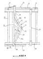
- Figure 1 is a partial view of a headlock according to the invention, in the open position.
- Figure 2 is a figure similar to that of the Figure 1, the headlock being in position closing.
- the stall portico partially shown on the drawings include, as is common, a upper spar 11, a lower spar 12 and vertical uprights 13 delimiting openings 10 to allow passage to the head of the animals.
- each opening 10 is provided with a balance 14 composed of two elements 14a and 14b pivoting on an axis 15.
- the pendulum 14 is suspended from a support 16 by through a pivot axis 17, located at a certain distance from the axis 15, above the latter.
- the support 16 is produced in the form of a bar substantially horizontal and integral at its end opposite the pivot axis 17, of the upright 13 which delimits the opening on the balance side, substantially at middle of the opening.
- slashes 25 and 26 Between the amount 13 and the support bar 16 are still attached, on both sides other of it, slashes 25 and 26 respectively.
- the lower slash 26 carries a stop 24 which limits the movement of pivoting of the element 14a around the axis 15.
- the lower end of the pendulum element 14a 14 is terminated by a fork 18 connected to a control rod 20 along the lower beam 12.
- the upper end of the element 14b is finished by a fork 19 which can slide along the upper spar 11.
- a valve 21 resting on a control rod 22 which runs along the upper side member 11.
- the control rod 22 is mounted to be able to pivot around its axis longitudinal and carries a stop 23.
- the valve and the stop are configured so that the valve can pass over the stop when the fork moves from left to right, but is blocked behind the stop after passing it. To free the fork then you have to rotate the rod command to clear the stop of the trajectory of the valve seen, for example from a 90 ° angle.
- the control rod 22 serves to disengage the valve 21 from stop 23 and puts the balance back in the open position.
- the opening movement is facilitated by the lower rod 20 and the stop 24 which allows at the same time the blocking of all mechanism.
- the headlock being in the closed position, it suffices to rotate the control rod 22 around its longitudinal axis to release the valve 21 from the stop 23. This allows the upper member 14b to pivot around the axis 15 and the animal to take out the head.
- the animal can push back the lower element 14a, this which puts the upper element 14b in vertical position closing (figure 2). Since in its open self-service position, pendulum 14 is blocked by the rod 20 and the stop 24 the headlock according to the invention provides an effective solution to noise and rapid wear problems inherent in known feeders.
Description
La présente invention se rapporte aux dispositifs installés devant une auge et destinés à limiter les mouvements des animaux en train de manger.The present invention relates to devices installed in front of a trough and intended to limit the movements of animals eating.
De tels dispositifs, appelés cornadis, sont couramment utilisés. On connaít notamment un cornadis, voir e.g. le document NL-A-9 000 107, dans lequel l'immobilisation de l'animal s'obtient par l'abaissement de la tête dans un cadre constitué, d'une part, par une colonne du portique et, d'autre part, par un balancier monté sur pivot et guidé par le longeron supérieur dudit portique. La fourche supérieure du balancier contient un clapet qui entre en contact avec un arrêt fixé sur un tube se trouvant sur le longeron supérieur et qui permet par un pivotement de 90° la position de verrouillage et de déverrouillage. Ce système a l'inconvénient de ne pouvoir empêcher l'étranglement des bêtes.Such devices, called head locks, are commonly used. We know in particular a headlock, see e.g. document NL-A-9 000 107, in which the immobilization of the animal is obtained by lowering the head in a constituted frame, on the one hand, by a column of the gantry and, on the other part, by a pendulum mounted on a pivot and guided by the upper spar of said gantry. The fork upper of the balance contains a valve which enters in contact with a stop fixed on a tube located on the upper beam and which allows by a 90 ° swivel the locking position and unlocking. This system has the disadvantage of not ability to prevent strangulation of animals.
Cet inconvénient est évité grâce à l'invention par un cornadis dans lequel chaque ouverture contient un balancier formé de deux éléments articulés autour d'un axe de manière à rendre l'élément supérieur indépendant de l'élément inférieur. L'élément inférieur est relié à son extrémité inférieure à une tringle de commande montée pour coulisser le long du longeron inférieur. L'extrémité supérieure de l'élément supérieur est munie d'un clapet coulissant le long d'une tige de commande qui s'étend parallèlement au longeron supérieur.This drawback is avoided thanks to the invention by a headlock in which each opening contains a pendulum formed of two elements articulated around an axis so as to make the element superior independent of the lower element. The element lower is connected at its lower end to a control rod mounted to slide along the lower spar. The upper end of the upper element is fitted with a sliding valve along a control rod that extends parallel to the upper beam.
Sur le support auquel est suspendu le balancier est placée une butée qui empêche tout mouvement du mécanisme lorsque l'élément inférieur se trouve en position inclinée. On the support to which the pendulum is suspended is placed a stop which prevents movement of the mechanism when the lower element is in tilted position.
Le cornadis conforme à l'invention permet un second déverrouillage sur le longeron inférieur du cornadis. Ce déverrouillage garantit une parfaite sécurité pour les animaux lorsque le mécanisme se trouve dans la position d'ouverture libre-service. De plus, ce cornadis s'avère plus silencieux.The feed lock according to the invention allows a second unlocking on the lower side member of the lock. This unlocking guarantees perfect security for animals when the mechanism is in the self-service open position. In addition, this head locks are quieter.
L'invention est exposée dans ce qui suit à l'aide des dessins annexés.The invention is set out in the following using the attached drawings.
La figure 1 est une vue partielle d'un cornadis conforme à l'invention, en position d'ouverture.Figure 1 is a partial view of a headlock according to the invention, in the open position.
La figure 2 est une figure analogue à celle de la figure 1, le cornadis se trouvant en position de fermeture.Figure 2 is a figure similar to that of the Figure 1, the headlock being in position closing.
Le portique de stalle représenté partiellement sur
les dessins comporte, ainsi qu'il est courant, un
longeron supérieur 11, un longeron inférieur 12 et
des montants verticaux 13 délimitant des ouvertures
10 pour laisser passage à la tête des animaux. Dans
chaque ouverture 10 est prévu un balancier 14 composé
de deux éléments 14a et 14b pivotant sur un axe 15.
Le balancier 14 est suspendu à un support 16 par
l'intermédiaire d'un axe pivot 17, situé à une
certaine distance de l'axe 15, au-dessus de celui-ci.
Le support 16 est réalisé sous forme d'une barre
sensiblement horizontale et solidaire à son extrémité
opposée à l'axe pivot 17, du montant 13 qui délimite
l'ouverture du côté du balancier, sensiblement au
milieu de l'ouverture. Entre le montant 13 et la
barre de support 16 sont encore fixées, de part et
d'autre de celle-ci, des barres obliques
respectivement 25 et 26. La barre oblique inférieure
26 porte une butée 24 qui limite le mouvement de
pivotement de l'élément 14a autour de l'axe 15. The stall portico partially shown on
the drawings include, as is common, a
L'extrémité inférieure de l'élément 14a du balancier
14 est terminée par une fourche 18 reliée à une
tringle de commande 20 longeant le longeron inférieur
12.The lower end of the
L'extrémité supérieure de l'élément 14b est terminée
par une fourche 19 pouvant coulisser le long du
longeron supérieur 11. Sur la fourche 19 est fixé un
clapet 21 reposant sur une tige de commande 22 qui
longe le longeron supérieur 11. La tige de commande
22 est montée pour pouvoir pivoter autour de son axe
longitudinal et porte un arrêt 23. Le clapet et
l'arrêt sont configurés de façon à ce que le clapet
puisse passer au-dessus de l'arrêt lorsque la fourche
se déplace de gauche à droite, mais est bloquée
derrière l'arrêt après l'avoir passé. Pour libérer
la fourche il faut alors faire tourner la tige de
commande pour dégager l'arrêt de la trajectoire du
clapet vue, par exemple d'un angle de 90°.The upper end of the element 14b is finished
by a
Chaque balancier 14 est susceptible de prendre
plusieurs positions:
La tige de commande 22 sert à dégager le clapet 21 de
l'arrêt 23 et permet de remettre le balancier dans la
position ouverte. Le mouvement d'ouverture est
facilité par la tringle inférieure 20 et la butée 24
qui permet en même temps le blocage de tout le
mécanisme.The
Le cornadis étant en position fermée, il suffit de
faire pivoter la tige de commande 22 autour de son
axe longitudinal pour libérer le clapet 21 de l'arrêt
23. Ceci permet à l'élément supérieur 14b de pivoter
autour de l'axe 15 et à l'animal de sortir la tête.The headlock being in the closed position, it suffices to
rotate the
Pour mettre le cornadis en position de sécurité, il
suffit d'effectuer une traction sur la tringle 20
dans le sens de la flèche notée B (figure 1) pour
mettre l'élément inférieur 14a en position inclinée.To put the headlock in the safety position, it
just pull on the
Par une légère pression indiquée par la flèche A,
l'animal peut repousser l'élément inférieur 14a, ce
qui met l'élément supérieur 14b en position verticale
de fermeture (figure 2). Etant donné que, dans sa
position ouverte de libre service, le balancier 14
est bloqué par la tige 20 et la butée 24 le cornadis
selon l'invention apporte une solution efficace aux
problèmes du bruit et de l'usure rapide inhérents aux
cornadis connus.By a slight pressure indicated by the arrow A,
the animal can push back the
Claims (3)
- Feeding fence comprising a portico including upper and lower beams and posts which define juxtaposed openings, the plane of each opening including a swivel device suspended to a support, wherein each swivel device is formed by two elements hingedly mounted about an axis, the lower element being connected at its lower end to a control rod mounted in a way to extend along the lower beam and the upper end of the upper element being provided with a locking member sliding along a control rod extending in a parallel relationship to the upper beam.
- Feeding fence according to claim 1, wherein the control rod extending in parallel relationship to the upper beam carries a stop retractable between a locking member locking position and a locking member releasing position.
- Feeding fence according to claim 1, comprising an abutment for locking the fence when the lower swivel element is in its inclined position.
Applications Claiming Priority (2)
| Application Number | Priority Date | Filing Date | Title |
|---|---|---|---|
| BE9700593A BE1011268A6 (en) | 1997-07-09 | 1997-07-09 | Improvements to cornadis. |
| BE9700593 | 1997-07-09 |
Publications (2)
| Publication Number | Publication Date |
|---|---|
| EP0890303A1 EP0890303A1 (en) | 1999-01-13 |
| EP0890303B1 true EP0890303B1 (en) | 2000-06-14 |
Family
ID=3890626
Family Applications (1)
| Application Number | Title | Priority Date | Filing Date |
|---|---|---|---|
| EP98112048A Expired - Lifetime EP0890303B1 (en) | 1997-07-09 | 1998-06-30 | Improved feeding stanchion |
Country Status (4)
| Country | Link |
|---|---|
| US (1) | US5970909A (en) |
| EP (1) | EP0890303B1 (en) |
| BE (1) | BE1011268A6 (en) |
| CA (1) | CA2243037C (en) |
Families Citing this family (2)
| Publication number | Priority date | Publication date | Assignee | Title |
|---|---|---|---|---|
| US20070047712A1 (en) * | 2003-03-07 | 2007-03-01 | Cirrus Logic, Inc. | Scalable, distributed architecture for fully connected network intercom system |
| CN109349144A (en) * | 2018-10-26 | 2019-02-19 | 贵州大学 | A kind of adjustable neck frame suitable for all ages and classes sheep |
Family Cites Families (5)
| Publication number | Priority date | Publication date | Assignee | Title |
|---|---|---|---|---|
| US4377131A (en) * | 1981-05-15 | 1983-03-22 | August Vandenberg | Stanchion construction |
| IT1203884B (en) * | 1986-04-16 | 1989-02-23 | Lentzen Paul | ARTICULATED COLLAR FOR FEEDER |
| NL9000107A (en) * | 1990-01-16 | 1991-08-16 | Johannes Martinus Willibrordus | Self catching cattle fodder gate - has top and horizontal girders with interconnected fixed and pivot bars |
| US4976224A (en) * | 1990-04-26 | 1990-12-11 | John Hatfield | Double hinged cattle stanchion apparatus |
| US5694887A (en) * | 1995-10-06 | 1997-12-09 | Vandenberg; August | Cattle stanchion with floating latch |
-
1997
- 1997-07-09 BE BE9700593A patent/BE1011268A6/en not_active IP Right Cessation
-
1998
- 1998-06-30 EP EP98112048A patent/EP0890303B1/en not_active Expired - Lifetime
- 1998-07-06 CA CA002243037A patent/CA2243037C/en not_active Expired - Lifetime
- 1998-07-08 US US09/112,121 patent/US5970909A/en not_active Expired - Fee Related
Also Published As
| Publication number | Publication date |
|---|---|
| US5970909A (en) | 1999-10-26 |
| EP0890303A1 (en) | 1999-01-13 |
| CA2243037C (en) | 2001-05-29 |
| CA2243037A1 (en) | 1999-01-09 |
| BE1011268A6 (en) | 1999-07-06 |
Similar Documents
| Publication | Publication Date | Title |
|---|---|---|
| EP0608164B1 (en) | Mobile anchorage permitting safe movement in an horizontal axis | |
| EP0890303B1 (en) | Improved feeding stanchion | |
| CA2343607A1 (en) | Training on cornadis | |
| EP1040753B1 (en) | Stanchion | |
| EP0562991A1 (en) | Closure system for animal cages, especially for pigs | |
| FR2638797A1 (en) | SLIDE PROFILE ALLOWING THE PRODUCTION OF FLOATING LOCK SLIDES | |
| FR2597300A1 (en) | Feeding rack | |
| LU82765A1 (en) | ANTI-FALL DEVICE WITH INSTANT LOCKING ACTION | |
| BE1009126A6 (en) | Stanchion improvement | |
| CA3200798A1 (en) | Feed barrier | |
| FR2728883A1 (en) | Mechanical safety device for lift user between levels for persons with reduced mobility e.g. elderly | |
| BE1005726A5 (en) | Cornadis | |
| FR2979799A1 (en) | Barrier e.g. swedish stanchion, for use in breeding enclosure for e.g. horned sheep to assure e.g. veterinary care, has application beam moved until release position from top to bottom so as to partially release access to side clearance | |
| FR2611801A1 (en) | Turnstile-type gate and use of such a gate | |
| EP2023778B1 (en) | Secure stand for baby changing mat | |
| FR2685164A1 (en) | Feeding grille for horned animals | |
| EP0097406B1 (en) | Device for tying an animal | |
| FR2783134A1 (en) | Access control for animal feeding point, has rectangle formed by horizontal and vertical bars, with lever arm pivoting to occupy closed vertical position or angled open position, with locking element carried by upper horizontal bar | |
| BE904606A (en) | CORNADIS | |
| DE2037659A1 (en) | Harvester | |
| FR2790189A1 (en) | Enclosure for bovines has frame with cross bars and uprights forming stalls with pivot bars to retain animals locked by upper bar | |
| FR3116989A1 (en) | HEADLOCKS | |
| FR2591846A1 (en) | Improvement to the support device of a portable reversible plough, of the type with a hanging wheel | |
| FR2611429A1 (en) | Improvement of milking installations | |
| FR2781120A1 (en) | Installation for automatic guiding and placing cattle in milking or feeding position |
Legal Events
| Date | Code | Title | Description |
|---|---|---|---|
| PUAI | Public reference made under article 153(3) epc to a published international application that has entered the european phase |
Free format text: ORIGINAL CODE: 0009012 |
|
| AK | Designated contracting states |
Kind code of ref document: A1 Designated state(s): BE FR LU NL |
|
| AX | Request for extension of the european patent |
Free format text: AL;LT;LV;MK;RO;SI |
|
| 17P | Request for examination filed |
Effective date: 19990517 |
|
| GRAG | Despatch of communication of intention to grant |
Free format text: ORIGINAL CODE: EPIDOS AGRA |
|
| 17Q | First examination report despatched |
Effective date: 19990729 |
|
| AKX | Designation fees paid |
Free format text: BE FR LU NL |
|
| REG | Reference to a national code |
Ref country code: DE Ref legal event code: 8566 |
|
| GRAG | Despatch of communication of intention to grant |
Free format text: ORIGINAL CODE: EPIDOS AGRA |
|
| GRAH | Despatch of communication of intention to grant a patent |
Free format text: ORIGINAL CODE: EPIDOS IGRA |
|
| GRAH | Despatch of communication of intention to grant a patent |
Free format text: ORIGINAL CODE: EPIDOS IGRA |
|
| GRAA | (expected) grant |
Free format text: ORIGINAL CODE: 0009210 |
|
| AK | Designated contracting states |
Kind code of ref document: B1 Designated state(s): BE FR LU NL |
|
| PLBE | No opposition filed within time limit |
Free format text: ORIGINAL CODE: 0009261 |
|
| STAA | Information on the status of an ep patent application or granted ep patent |
Free format text: STATUS: NO OPPOSITION FILED WITHIN TIME LIMIT |
|
| RAP2 | Party data changed (patent owner data changed or rights of a patent transferred) |
Owner name: N.V. AGRINBO S.A. |
|
| RIN2 | Information on inventor provided after grant (corrected) |
Free format text: VANDEVELDE, NOEL |
|
| 26N | No opposition filed | ||
| NLT2 | Nl: modifications (of names), taken from the european patent patent bulletin |
Owner name: N.V. AGRINBO S.A. |
|
| NLS | Nl: assignments of ep-patents |
Owner name: N.V. AGRINBO S.A. |
|
| REG | Reference to a national code |
Ref country code: FR Ref legal event code: TP |
|
| PGFP | Annual fee paid to national office [announced via postgrant information from national office to epo] |
Ref country code: FR Payment date: 20050428 Year of fee payment: 8 |
|
| PGFP | Annual fee paid to national office [announced via postgrant information from national office to epo] |
Ref country code: LU Payment date: 20050520 Year of fee payment: 8 |
|
| PGFP | Annual fee paid to national office [announced via postgrant information from national office to epo] |
Ref country code: NL Payment date: 20050627 Year of fee payment: 8 |
|
| PGFP | Annual fee paid to national office [announced via postgrant information from national office to epo] |
Ref country code: BE Payment date: 20050707 Year of fee payment: 8 |
|
| PG25 | Lapsed in a contracting state [announced via postgrant information from national office to epo] |
Ref country code: BE Free format text: LAPSE BECAUSE OF NON-PAYMENT OF DUE FEES Effective date: 20060630 |
|
| PG25 | Lapsed in a contracting state [announced via postgrant information from national office to epo] |
Ref country code: NL Free format text: LAPSE BECAUSE OF NON-PAYMENT OF DUE FEES Effective date: 20070101 |
|
| NLV4 | Nl: lapsed or anulled due to non-payment of the annual fee |
Effective date: 20070101 |
|
| REG | Reference to a national code |
Ref country code: FR Ref legal event code: ST Effective date: 20070228 |
|
| BERE | Be: lapsed |
Owner name: S.A. *AGRINBO N.V. Effective date: 20060630 |
|
| PG25 | Lapsed in a contracting state [announced via postgrant information from national office to epo] |
Ref country code: FR Free format text: LAPSE BECAUSE OF NON-PAYMENT OF DUE FEES Effective date: 20060630 |
|
| PG25 | Lapsed in a contracting state [announced via postgrant information from national office to epo] |
Ref country code: LU Free format text: LAPSE BECAUSE OF NON-PAYMENT OF DUE FEES Effective date: 20060630 |