EP0890055B1 - Dispositif permettant de raccorder un appareil mesurant la pression de fluides - Google Patents
Dispositif permettant de raccorder un appareil mesurant la pression de fluides Download PDFInfo
- Publication number
- EP0890055B1 EP0890055B1 EP97918024A EP97918024A EP0890055B1 EP 0890055 B1 EP0890055 B1 EP 0890055B1 EP 97918024 A EP97918024 A EP 97918024A EP 97918024 A EP97918024 A EP 97918024A EP 0890055 B1 EP0890055 B1 EP 0890055B1
- Authority
- EP
- European Patent Office
- Prior art keywords
- needle
- blind hole
- clamp
- face
- bore
- Prior art date
- Legal status (The legal status is an assumption and is not a legal conclusion. Google has not performed a legal analysis and makes no representation as to the accuracy of the status listed.)
- Expired - Lifetime
Links
Images


Classifications
-
- F—MECHANICAL ENGINEERING; LIGHTING; HEATING; WEAPONS; BLASTING
- F16—ENGINEERING ELEMENTS AND UNITS; GENERAL MEASURES FOR PRODUCING AND MAINTAINING EFFECTIVE FUNCTIONING OF MACHINES OR INSTALLATIONS; THERMAL INSULATION IN GENERAL
- F16L—PIPES; JOINTS OR FITTINGS FOR PIPES; SUPPORTS FOR PIPES, CABLES OR PROTECTIVE TUBING; MEANS FOR THERMAL INSULATION IN GENERAL
- F16L41/00—Branching pipes; Joining pipes to walls
- F16L41/04—Tapping pipe walls, i.e. making connections through the walls of pipes while they are carrying fluids; Fittings therefor
- F16L41/06—Tapping pipe walls, i.e. making connections through the walls of pipes while they are carrying fluids; Fittings therefor making use of attaching means embracing the pipe
- F16L41/065—Tapping pipe walls, i.e. making connections through the walls of pipes while they are carrying fluids; Fittings therefor making use of attaching means embracing the pipe without removal of material
-
- G—PHYSICS
- G01—MEASURING; TESTING
- G01L—MEASURING FORCE, STRESS, TORQUE, WORK, MECHANICAL POWER, MECHANICAL EFFICIENCY, OR FLUID PRESSURE
- G01L19/00—Details of, or accessories for, apparatus for measuring steady or quasi-steady pressure of a fluent medium insofar as such details or accessories are not special to particular types of pressure gauges
- G01L19/0007—Fluidic connecting means
-
- Y—GENERAL TAGGING OF NEW TECHNOLOGICAL DEVELOPMENTS; GENERAL TAGGING OF CROSS-SECTIONAL TECHNOLOGIES SPANNING OVER SEVERAL SECTIONS OF THE IPC; TECHNICAL SUBJECTS COVERED BY FORMER USPC CROSS-REFERENCE ART COLLECTIONS [XRACs] AND DIGESTS
- Y10—TECHNICAL SUBJECTS COVERED BY FORMER USPC
- Y10T—TECHNICAL SUBJECTS COVERED BY FORMER US CLASSIFICATION
- Y10T137/00—Fluid handling
- Y10T137/598—With repair, tapping, assembly, or disassembly means
- Y10T137/612—Tapping a pipe, keg, or apertured tank under pressure
- Y10T137/6123—With aperture forming means
-
- Y—GENERAL TAGGING OF NEW TECHNOLOGICAL DEVELOPMENTS; GENERAL TAGGING OF CROSS-SECTIONAL TECHNOLOGIES SPANNING OVER SEVERAL SECTIONS OF THE IPC; TECHNICAL SUBJECTS COVERED BY FORMER USPC CROSS-REFERENCE ART COLLECTIONS [XRACs] AND DIGESTS
- Y10—TECHNICAL SUBJECTS COVERED BY FORMER USPC
- Y10T—TECHNICAL SUBJECTS COVERED BY FORMER US CLASSIFICATION
- Y10T408/00—Cutting by use of rotating axially moving tool
- Y10T408/55—Cutting by use of rotating axially moving tool with work-engaging structure other than Tool or tool-support
- Y10T408/561—Having tool-opposing, work-engaging surface
- Y10T408/5628—Tool having screw-thread engaging frame to cause infeed
-
- Y—GENERAL TAGGING OF NEW TECHNOLOGICAL DEVELOPMENTS; GENERAL TAGGING OF CROSS-SECTIONAL TECHNOLOGIES SPANNING OVER SEVERAL SECTIONS OF THE IPC; TECHNICAL SUBJECTS COVERED BY FORMER USPC CROSS-REFERENCE ART COLLECTIONS [XRACs] AND DIGESTS
- Y10—TECHNICAL SUBJECTS COVERED BY FORMER USPC
- Y10T—TECHNICAL SUBJECTS COVERED BY FORMER US CLASSIFICATION
- Y10T408/00—Cutting by use of rotating axially moving tool
- Y10T408/55—Cutting by use of rotating axially moving tool with work-engaging structure other than Tool or tool-support
- Y10T408/564—Movable relative to Tool along tool-axis
- Y10T408/5647—Movable relative to Tool along tool-axis including means to move Tool
-
- Y—GENERAL TAGGING OF NEW TECHNOLOGICAL DEVELOPMENTS; GENERAL TAGGING OF CROSS-SECTIONAL TECHNOLOGIES SPANNING OVER SEVERAL SECTIONS OF THE IPC; TECHNICAL SUBJECTS COVERED BY FORMER USPC CROSS-REFERENCE ART COLLECTIONS [XRACs] AND DIGESTS
- Y10—TECHNICAL SUBJECTS COVERED BY FORMER USPC
- Y10T—TECHNICAL SUBJECTS COVERED BY FORMER US CLASSIFICATION
- Y10T408/00—Cutting by use of rotating axially moving tool
- Y10T408/65—Means to drive tool
- Y10T408/675—Means to drive tool including means to move Tool along tool-axis
- Y10T408/6793—Screw coaxial with Tool
Definitions
- the invention relates to a device for connection one the pressure of fluids, especially hydraulic oil, measuring device to a fluid pressure or pressureless piping that can be filled with fluid
- axially guided needle limits axially is guided adjustable, the needle by means of a threadedly connected to the clamp bracket Threaded spindle, which is coaxial to the longitudinal axis of the needle is directed, axially displaceable, and wherein preferably the clamp bracket has a bore, to which a pressure measuring device can be connected and with the leak of the pipe through the needle can be generated, has an open connection
- the threaded spindle is a coaxial has directed blind hole into which the shaft the needle can be inserted coaxially, and between the Bottom of the blind hole and the bottom facing end face of the shaft of the needle Center
- a generic device is from the US-A-3,762,263. However, with the known device only a hole in a tube contribute. The flow of fluid media, especially hydraulic oil through this hole and through the device for example for the purpose of Connection of a pressure gauge, but is there not provided.
- Another similar device is for example known from US-A-3 198 206.
- the known Device is a pressure measuring clamp with two Clamp brackets known to each other by means of Screws are attached.
- an axially guided needle which is held by means of a threaded spindle is axially adjustable.
- the Threaded spindle is through one on the clamp bracket molded threaded connector and one on it screwed threaded cap formed.
- the threaded cap has an eccentric perforation through which a Head-provided part of the needle can.
- the needle is released with the threaded cap eccentrically inserted into the cap and then then moved the cap onto the Threaded construction of the clamp bracket screwed on can be and an essentially centric seat the needle is reached.
- EP-PS 03 10 601 B1 Device for connecting the pressure of fluids measuring device to a pressurized medium Pipeline known, in which the pipeline means a spray drill is cut, the only Chip chips generated.
- the Pipe wall can be pierced without chips be generated.
- EP-A-0 429 904 known with a fluid-carrying line pierced and liquid drained from the line can be. This leads to a lateral discharge the liquid from the pierced pipe what is disadvantageous in that the side next to the Device to an assembly and arrangement room Must be available. A tight installation is for such training cannot be used.
- the object of a device Generic type to create in which the danger the needle break is largely avoided, and at a central and axial arrangement of the pressure meter to be connected is enabled.
- the training according to the invention is both at Devices usable that only serve to punch an unpressurized pipeline to then a measuring clamp with connection for a pressure measuring device to be able to arrange at this point.
- the device but is also for a combined device usable, in which a connecting line for a Pressure measuring device is integrated. In this case can also cut a pressurized Pipeline, the pressure then through the connected pressure measuring device immediately can be recorded.
- the training according to the invention represents a Device available where the needle is self-centered without constraint, so that at one Actuation of the threaded spindle and a corresponding one Advance the needle to the wall of the clamped Tube ensures that the needle is largely So there is a risk of breakage from lateral forces does not exist.
- Training is also straightforward in handling and manufacturing as it is only is necessary, the threaded spindle as a threaded bolt train with blind hole, the Threaded spindle in a corresponding threaded hole of the clamp bracket of the measuring clamp can be screwed in. Because the needle is only with her Face directly or indirectly on the Bottom surface of the blind hole supports and between centering means on these surfaces or on these surfaces are trained, self-centering of the Needle reached when operating the threaded spindle.
- the training according to which the end face of the shaft the needle is convex or as a centering ball is formed and between this end face and the bottom of the blind hole two circular disc springs are arranged for the desired constraint-free Self-centering is very beneficial, with one being of the two disc springs at the bottom of the blind hole can support and the other on the end face of the Shaft of the needle.
- the two disc springs can if they turn relative to each other for example due to material roughness or other special features rubbing against the bottom of the blind hole or rest on the end face of the needle.
- the arrangement of the disc springs also ensures that a relative displacement of the needle is possible without that lateral forces act on the needle.
- the second guide sleeve in the drillable hole of the needle Clamp bracket used firmly, in particular is pressed into one of the form in the clamp bracket of the enclosed pipe and adapted to it Metallic half-shell inserted is that the half-shell is circular or has a circular recess into which an O-ring is inserted that the O-ring is radially on the outside the edge of the recess, on the pipe jacket and on a portion of the inner shell of the clamp bracket as well as radially inside on the outer jacket of the second Sealing sleeve in the area that supports protrudes axially over the inner clamp of the clamp bracket.
- the as Support surface for the edge of the O-ring Recess of the half-shell is aligned so that it is part of a cone shell, the tip of which lies in the central axis of the enclosed pipe.
- This training is also used for secure sealing conducive to high pressures.
- the Bottom of the blind hole of the threaded spindle concave or is conically hollowed out.
- the needle is off hardened steel and the clamp bracket made of soft Steel, in particular free-cutting steel, exists.
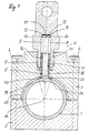
- Figures 1 to 5 is an inventive Device shown that no pressure relief port has, but only serves first a pressureless pipe to be used, whereby according to Figure 3, a corresponding arrangement takes place, then according to Figure 4 pierce the corresponding hole in the pipe wall becomes.
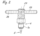
- the actual one can be added later Punching device alone in Figure 2 is shown to be removed and a Measuring clamp with measuring connection according to FIG. 5 on the Punching point are applied.
- the Measuring connection integrated in the punching device is the Measuring connection integrated in the punching device.
- an apparatus for Connection of the pressure of fluids for example hydraulic oil, measuring device a pressurized or non-pressurized fluid, pipeline 1 to which fluid can be applied.
- the device consists of one to the Pipeline 1 can be clamped radially tightly Clamp with two clamps 2 and 3.
- the Clamp brackets are connected to each other via screws 4 connected.
- one clamp bracket 3 is one radially directed to the casing of the pipeline 1, axially guided needle 5 limited axially adjustable performed, the needle by means of a Clamp bracket 3 connected by thread Threaded spindle 6, which is coaxial to the longitudinal axis of the needle is directed axially.
- the threaded spindle 6 has a coaxial blind hole 8 in the the shaft 9 of the needle 5 can be inserted coaxially.
- the threaded spindle 6 consists of a bolt-like part with external thread 10, which in a corresponding stepped bore 11 of the clamp bracket 3 can be screwed in.
- centering means arranged or designed by means of which The needle is self-centered without constraint.
- Embodiments is the end face 13 of the Shank 9 of the needle 5 convex or also as Centering cone is excellent. Between this end face 13 and the bottom 12 of the Blind holes 8 are two annular Disc springs 15 arranged.
- the needle 5 points in Connection to the end face 13 first recessed cylindrical area to which a first polygonal shaft area followed. Due to the polygon formation of the Shank is related to the circular Cross section of the blind hole 8 a way to Passage of fluids reached.
- the stem is subsequently tapered (at 16), this taper 16 in one held in the blind hole 8, up to the first reaching the mouth of the blind hole Guide sleeve 17 is inserted.
- the guide sleeve has axial over part of its longitudinal course Support ribs 18, so that here too an axial Passage for existing fluid is created. Grooves can also be used instead of supporting ribs be trained.
- the second guide sleeve 18 is in the of the needle 5 penetrable bore of the Clamp bracket 3 used firmly, for example pressed in to leakage between the guide sleeve and the surrounding clamp material.
- the clamp bracket 3 is one of the shape of enclosed tube 1 adapted to its jacket adjacent, metallic half-shell 23 created.
- the Half-shell 23 has a circular or circular recess into which an O-ring 24th is inserted.
- the O-ring 24 is supported radially outside on the edge 25 of the recess of the Half-shell 23 on.
- the O-ring is also supported the jacket of the tube 1 and in a partial area of the inner shell of the clamp bracket 3 and radially inside of the outer jacket of the second guide sleeve 18 sealing. This area protrudes above the Inner jacket of the clamp bracket 3 in front.
- the needle 5 is preferably made of hardened Steel, while the clamp bracket 2, 3 made good machinable steel, for example free cutting steel consist.
Landscapes
- Engineering & Computer Science (AREA)
- General Engineering & Computer Science (AREA)
- Mechanical Engineering (AREA)
- Physics & Mathematics (AREA)
- General Physics & Mathematics (AREA)
- Measuring Fluid Pressure (AREA)
- Infusion, Injection, And Reservoir Apparatuses (AREA)
Claims (5)
- Dispositif permettant de raccorder un appareil mesurant la pression de fluides à une conduite (1) soumise à la pression d'un fluide ou non soumise à la pression d'un fluide mais pouvant recevoir un fluide, à l'aide d'un collier de serrage pouvant être fixé radialement sur la conduite (1) et assurant l'étanchéité, dans l'un des étriers (3) duquel une aiguille (5) guidée axialement et orientée radialement par rapport à l'enveloppe de la conduite est guidée de manière à pouvoir être déplacée axialement de façon limitée, sachant que l'aiguille peut être déplacée axialement au moyen d'une broche filetée (6) reliée par ses filets de vis à l'étrier du collier (3), qui est orientée coaxialement par rapport à l'axe longitudinal de l'aiguille, déplaçable axialement et sachant que l'étrier du collier (3) présente de préférence un perçage permettant de raccorder un appareil mesurant la pression (7) et communiquant directement avec le point de fuite de la conduite (1) pouvant être créé par l'aiguille (5), sachant en outre que la broche filetée (6) présente un perçage borgne (8) orienté de manière coaxiale dans lequel peut être enfoncée coaxialement la tige (9) de l'aiguille (5) et qu'entre le fond (12) du perçage borgne (8) et la surface frontale (13) de la tige (8) de l'aiguille (5) qui est tournée vers le fond (12) sont réalisés ou disposés des moyens de centrage (14) permettant un centrage automatique de l'aiguille (5), caractérisé en ce que la surface frontale (13) de la tige (9) de l'aiguille (5) est convexe ou est réalisée en tant que bille de centrage, et en ce qu'entre cette surface frontale (13) et le fond (12) du perçage borgne sont disposés deux ressorts à disques semblables à des anneaux de cercle (15) munis d'un perçage central (21), en ce que l'aiguille (5) présente à la suite de la surface frontale (13) un premier segment de tige polygonal ou une tige ronde avec des nervures longitudinales, puis se rétrécit avant de traverser une première douille de guidage (17) maintenue dans le perçage borgne (8) et s'étendant jusqu'à l'ouverture de ce dernier, qui présente des nervures d'appui axiales (18), puis traverse, de préférence avec un faible jeu, une seconde douille de guidage (18) fixée dans le corps du collier de serrage (3), douille de guidage de l'ouverture de laquelle il est possible de faire sortir la pointe rétrécie de l'aiguille (5), si bien qu'une fente de passage du fluide est formée depuis le point de fuite (19) à créer jusqu'au fond (12) du perçage borgne (8) dont part le perçage (22) permettant de raccorder un appareil de mesure de la pression (7), en ce que la surface frontale (13) de la tige (9) de l'aiguille présente au moins une fente transversale (20) qui relie la fente de passage du fluide au perçage central (21) des ressorts à disques (15), et en ce que le perçage (22) permettant de raccorder un appareil mesurant la pression (7) part axialement du fond (12) du perçage borgne.
- Dispositif selon la revendication 1, caractérisé en ce que la seconde douille de guidage (18) est logée ou enfoncée fixement dans le perçage de l'étrier du collier (3) que l'aiguille (5) peut traverser, en ce qu'une demi-coquille (23) métallique adaptée à la forme du tuyau (1) qu'elle entoure et appliquée contre l'enveloppe de ce dernier est posée dans l'étrier du collier (3), en ce que la demi-coquille (23) présente un évidement circulaire ou semblable à un cercle dans lequel est placé un joint torique d'étanchéité (24), en ce que le joint torique d'étanchéité (24) prend appui radialement à l'extérieur sur l'arête du bord de l'évidement, sur l'enveloppe du tuyau et sur une partie de l'enveloppe intérieure de l'étrier du collier (3) ainsi que radialement à l'intérieur sur l'enveloppe extérieure de la seconde douille de guidage (18), de manière à réaliser l'étanchéité, dans la zone qui dépasse axialement de l'enveloppe intérieure de l'étrier du collier.
- Dispositif selon la revendication 2, caractérisé en ce que l'arête du bord (25) de l'évidement de la demi-coquille (23) qui sert de surface d'appui au joint torique d'étanchéité (24) est orientée de telle manière qu'elle fait partie d'une enveloppe conique dont la pointe est située sur l'axe médian du tuyau entouré (1).
- Dispositif selon l'une des revendications 1 à 3, caractérisé en ce que le fond (12) du perçage borgne (8) de la broche filetée (6) est concave ou creusé en forme de cône.
- Dispositif selon l'une des revendications 1 à 4, caractérisé en ce que l'aiguille (5) est en acier trempé et les étriers du collier (3, 4) en acier doux, notamment en acier de décolletage.
Applications Claiming Priority (3)
| Application Number | Priority Date | Filing Date | Title |
|---|---|---|---|
| DE1996113687 DE19613687C1 (de) | 1996-04-05 | 1996-04-05 | Vorrichtung zum Anschluß eines den Druck von Fluiden messenden Gerätes |
| DE19613687 | 1996-04-05 | ||
| PCT/DE1997/000515 WO1997038257A1 (fr) | 1996-04-05 | 1997-03-13 | Dispositif permettant de raccorder un appareil mesurant la pression de fluides |
Publications (2)
| Publication Number | Publication Date |
|---|---|
| EP0890055A1 EP0890055A1 (fr) | 1999-01-13 |
| EP0890055B1 true EP0890055B1 (fr) | 2002-09-11 |
Family
ID=7790577
Family Applications (1)
| Application Number | Title | Priority Date | Filing Date |
|---|---|---|---|
| EP97918024A Expired - Lifetime EP0890055B1 (fr) | 1996-04-05 | 1997-03-13 | Dispositif permettant de raccorder un appareil mesurant la pression de fluides |
Country Status (5)
| Country | Link |
|---|---|
| US (1) | US5829474A (fr) |
| EP (1) | EP0890055B1 (fr) |
| AU (1) | AU2632497A (fr) |
| DE (1) | DE19613687C1 (fr) |
| WO (1) | WO1997038257A1 (fr) |
Families Citing this family (7)
| Publication number | Priority date | Publication date | Assignee | Title |
|---|---|---|---|---|
| US6612330B1 (en) * | 2000-07-06 | 2003-09-02 | Keyspan Corporation | No interrupt service tee and method |
| US6684709B2 (en) * | 2001-10-29 | 2004-02-03 | Dwight N. Johnson | Pressure transducer with captured non compressible liquid volume defining neutral condition |
| US7219684B2 (en) * | 2005-01-28 | 2007-05-22 | Rain Bird Corporation | Saddle tee and tool for irrigation lines |
| US9661807B2 (en) | 2012-05-24 | 2017-05-30 | Rain Bird Corporation | Conduit with connector and assembly thereof |
| US10537073B2 (en) | 2012-05-24 | 2020-01-21 | Rain Bird Corporation | Conduit with connector and assembly thereof |
| US9668431B2 (en) | 2013-11-22 | 2017-06-06 | Rain Bird Corporation | Conduit with connector and assembly thereof |
| JP6285780B2 (ja) * | 2014-03-31 | 2018-02-28 | 積水化学工業株式会社 | 分岐継手の既設配管への接合方法及び穿孔冶具 |
Family Cites Families (23)
| Publication number | Priority date | Publication date | Assignee | Title |
|---|---|---|---|---|
| US1763927A (en) * | 1926-07-17 | 1930-06-17 | Nat Refrigeration Corp | Valve |
| US2664313A (en) * | 1950-07-28 | 1953-12-29 | Ono Tsurukichi | Fuel injection apparatus for injection engines |
| US3115889A (en) * | 1960-12-27 | 1963-12-31 | Imp Eastman Corp | Line tapping valve |
| US3198206A (en) * | 1961-08-01 | 1965-08-03 | Thomas F O'brien | Piercing valve |
| GB1069917A (en) * | 1963-11-21 | 1967-05-24 | British Oxygen Co Ltd | Fluid regulating valve mechanism |
| US3252474A (en) * | 1964-05-07 | 1966-05-24 | Sealed Unit Parts Co Inc | Line tap valves |
| DE1500245A1 (de) * | 1964-08-25 | 1969-05-22 | Chiaki Sugimoto | Absperrorgan mit Kugeldichtung |
| US3428075A (en) * | 1966-08-08 | 1969-02-18 | Watsco Inc | Spring retractable line piercing valve |
| DE1301678B (de) * | 1967-03-02 | 1969-08-21 | British Oxygen Co Ltd | Ventil zur Entnahme von Gas aus Druckgasbehaeltern |
| US3606398A (en) * | 1969-05-19 | 1971-09-20 | Franco Bocceda | Pipe union device of rapid application for fluid feedline offtakes |
| IT983104B (it) * | 1971-02-15 | 1974-10-31 | Bocceda F | Dispositivo per eseguire fori in condotti di rame ottone e mate riali plastici come pvc e simili per fluidi aria e gas |
| US3973584A (en) * | 1975-02-18 | 1976-08-10 | Eugene T. McKinnon | Piercing valve for tapping pipelines |
| US4018246A (en) * | 1975-06-02 | 1977-04-19 | Watsco, Inc. | Line tap valve |
| US3978881A (en) * | 1975-06-05 | 1976-09-07 | The Westward Company | Gas line pierce valve |
| US4204559A (en) * | 1978-04-17 | 1980-05-27 | Wagner Stuart J | Line tap valve |
| US4537214A (en) * | 1984-11-19 | 1985-08-27 | Gem Products, Inc. | Single seal pipeline tapping fixture having secure valve |
| US4611624A (en) * | 1985-09-12 | 1986-09-16 | Watsco, Inc. | Line piercing valve assembly |
| US4598731A (en) * | 1985-10-28 | 1986-07-08 | Colson Dale G | Valve assembly for placement over a capped, stub-out which is under water pressure in a dwelling |
| DE3790274D2 (en) * | 1986-05-27 | 1988-06-01 | Bolender Kubitz Masch Bkm | Device for connecting a pressure-gauge to a pipeline |
| US4955406A (en) * | 1989-04-20 | 1990-09-11 | I.W. Industries | Connector for water pipes |
| DE3939248A1 (de) * | 1989-11-28 | 1991-05-29 | Electrolux Siegen Gmbh | Vorrichtung zum anstechen von leitungen |
| FR2663394B1 (fr) * | 1990-06-14 | 1992-09-25 | Snecma | Dispositif obturateur a bille libre a jeux regles. |
| US5353831A (en) * | 1994-02-25 | 1994-10-11 | Watsco Components, Inc. | Tube-piercing clamp on valve assembly |
-
1996
- 1996-04-05 DE DE1996113687 patent/DE19613687C1/de not_active Expired - Fee Related
-
1997
- 1997-03-13 EP EP97918024A patent/EP0890055B1/fr not_active Expired - Lifetime
- 1997-03-13 WO PCT/DE1997/000515 patent/WO1997038257A1/fr active IP Right Grant
- 1997-03-13 AU AU26324/97A patent/AU2632497A/en not_active Abandoned
- 1997-04-04 US US08/832,983 patent/US5829474A/en not_active Expired - Fee Related
Also Published As
| Publication number | Publication date |
|---|---|
| US5829474A (en) | 1998-11-03 |
| AU2632497A (en) | 1997-10-29 |
| WO1997038257A1 (fr) | 1997-10-16 |
| EP0890055A1 (fr) | 1999-01-13 |
| DE19613687C1 (de) | 1997-06-26 |
Similar Documents
| Publication | Publication Date | Title |
|---|---|---|
| EP1693134B1 (fr) | Porte-taraud | |
| DE102004016305B4 (de) | Pressvorrichtung | |
| DE69714781T2 (de) | Hydromechanisches futter | |
| WO2005044491A1 (fr) | Dispositif de serrage extensible | |
| DE19525574C1 (de) | Spannvorrichtung zum genauen gegenseitigen Fixieren zweier Bauteile | |
| EP0890055B1 (fr) | Dispositif permettant de raccorder un appareil mesurant la pression de fluides | |
| DE3912503A1 (de) | Spanneinrichtung fuer auswechselbare werkzeugkoepfe | |
| EP2314403B1 (fr) | Dispositif de tension | |
| CH677889A5 (fr) | ||
| EP0310601B1 (fr) | Dispositif pour raccorder un manometre sur une canalisation | |
| DE2750367C2 (de) | Werkzeughalter für Bohrer | |
| EP2103369B1 (fr) | Mandrin expansible | |
| EP2182258A1 (fr) | Partie supérieure de soupape | |
| EP2008748A2 (fr) | Mandrin à pince de serrage | |
| EP0486532B1 (fr) | Outil pour machines-outils | |
| DE29606305U1 (de) | Vorrichtung zum Anschluß eines den Druck von Fluiden messenden Gerätes | |
| DE2208280A1 (de) | Spannvorrichtung für Schraubenbolzen | |
| EP4155023A1 (fr) | Logement pour un outil rotatif | |
| DE10125154B4 (de) | Vorrichtung zum lösbaren Halten eines Werkzeuges sowie Spannhülse hierfür | |
| WO2003066280A1 (fr) | Element de serrage | |
| DE20105764U1 (de) | Vorrichtung zum Bearbeiten von Werkstücken | |
| DE69605323T2 (de) | Vorrichtung zur einspritzung von flüssigkeit in ein holzstück | |
| EP1446575B1 (fr) | Soupape d'injection de carburant pour moteurs a combustion interne | |
| DE3617804C1 (en) | Device for connecting a pressure measuring instrument to a pipeline | |
| DE9002248U1 (de) | Dehnspannvorrichtung |
Legal Events
| Date | Code | Title | Description |
|---|---|---|---|
| PUAI | Public reference made under article 153(3) epc to a published international application that has entered the european phase |
Free format text: ORIGINAL CODE: 0009012 |
|
| 17P | Request for examination filed |
Effective date: 19980706 |
|
| AK | Designated contracting states |
Kind code of ref document: A1 Designated state(s): FR GB IT |
|
| 17Q | First examination report despatched |
Effective date: 20011029 |
|
| GRAG | Despatch of communication of intention to grant |
Free format text: ORIGINAL CODE: EPIDOS AGRA |
|
| GRAG | Despatch of communication of intention to grant |
Free format text: ORIGINAL CODE: EPIDOS AGRA |
|
| GRAH | Despatch of communication of intention to grant a patent |
Free format text: ORIGINAL CODE: EPIDOS IGRA |
|
| GRAH | Despatch of communication of intention to grant a patent |
Free format text: ORIGINAL CODE: EPIDOS IGRA |
|
| GRAA | (expected) grant |
Free format text: ORIGINAL CODE: 0009210 |
|
| AK | Designated contracting states |
Kind code of ref document: B1 Designated state(s): FR GB IT |
|
| REG | Reference to a national code |
Ref country code: GB Ref legal event code: FG4D Free format text: NOT ENGLISH |
|
| GBT | Gb: translation of ep patent filed (gb section 77(6)(a)/1977) |
Effective date: 20030107 |
|
| PG25 | Lapsed in a contracting state [announced via postgrant information from national office to epo] |
Ref country code: GB Free format text: LAPSE BECAUSE OF NON-PAYMENT OF DUE FEES Effective date: 20030313 |
|
| ET | Fr: translation filed | ||
| PLBE | No opposition filed within time limit |
Free format text: ORIGINAL CODE: 0009261 |
|
| STAA | Information on the status of an ep patent application or granted ep patent |
Free format text: STATUS: NO OPPOSITION FILED WITHIN TIME LIMIT |
|
| 26N | No opposition filed |
Effective date: 20030612 |
|
| GBPC | Gb: european patent ceased through non-payment of renewal fee |
Effective date: 20030313 |
|
| PG25 | Lapsed in a contracting state [announced via postgrant information from national office to epo] |
Ref country code: FR Free format text: LAPSE BECAUSE OF NON-PAYMENT OF DUE FEES Effective date: 20031127 |
|
| REG | Reference to a national code |
Ref country code: FR Ref legal event code: ST |
|
| PG25 | Lapsed in a contracting state [announced via postgrant information from national office to epo] |
Ref country code: IT Free format text: LAPSE BECAUSE OF NON-PAYMENT OF DUE FEES Effective date: 20050313 |