EP0889943B1 - Wirbelschichtreaktorsystem und methode zu seinem betrieb - Google Patents
Wirbelschichtreaktorsystem und methode zu seinem betrieb Download PDFInfo
- Publication number
- EP0889943B1 EP0889943B1 EP96903020A EP96903020A EP0889943B1 EP 0889943 B1 EP0889943 B1 EP 0889943B1 EP 96903020 A EP96903020 A EP 96903020A EP 96903020 A EP96903020 A EP 96903020A EP 0889943 B1 EP0889943 B1 EP 0889943B1
- Authority
- EP
- European Patent Office
- Prior art keywords
- gas
- separator
- particles
- outlet
- solid
- Prior art date
- Legal status (The legal status is an assumption and is not a legal conclusion. Google has not performed a legal analysis and makes no representation as to the accuracy of the status listed.)
- Expired - Lifetime
Links
- 238000000034 method Methods 0.000 title claims description 23
- 239000002245 particle Substances 0.000 claims description 86
- 239000000463 material Substances 0.000 claims description 38
- 239000007787 solid Substances 0.000 claims description 38
- 238000001816 cooling Methods 0.000 claims description 22
- 239000000446 fuel Substances 0.000 claims description 16
- 239000011343 solid material Substances 0.000 claims description 9
- 238000007599 discharging Methods 0.000 claims description 6
- 238000006243 chemical reaction Methods 0.000 claims description 4
- 238000005243 fluidization Methods 0.000 claims description 2
- 239000007789 gas Substances 0.000 description 103
- 238000002309 gasification Methods 0.000 description 9
- 238000004140 cleaning Methods 0.000 description 8
- 238000002485 combustion reaction Methods 0.000 description 6
- 239000000126 substance Substances 0.000 description 5
- 230000000694 effects Effects 0.000 description 4
- 239000000047 product Substances 0.000 description 4
- 239000004071 soot Substances 0.000 description 4
- 239000000654 additive Substances 0.000 description 3
- 150000001875 compounds Chemical class 0.000 description 3
- 238000000151 deposition Methods 0.000 description 3
- 239000004576 sand Substances 0.000 description 3
- OKTJSMMVPCPJKN-UHFFFAOYSA-N Carbon Chemical compound [C] OKTJSMMVPCPJKN-UHFFFAOYSA-N 0.000 description 2
- 235000019738 Limestone Nutrition 0.000 description 2
- 238000009825 accumulation Methods 0.000 description 2
- 239000003513 alkali Substances 0.000 description 2
- 229910052799 carbon Inorganic materials 0.000 description 2
- 239000011362 coarse particle Substances 0.000 description 2
- 238000001914 filtration Methods 0.000 description 2
- 239000006028 limestone Substances 0.000 description 2
- 230000001154 acute effect Effects 0.000 description 1
- 230000002411 adverse Effects 0.000 description 1
- 229910000272 alkali metal oxide Inorganic materials 0.000 description 1
- 230000000903 blocking effect Effects 0.000 description 1
- 230000005587 bubbling Effects 0.000 description 1
- 239000003575 carbonaceous material Substances 0.000 description 1
- 239000003638 chemical reducing agent Substances 0.000 description 1
- 238000010276 construction Methods 0.000 description 1
- 238000005260 corrosion Methods 0.000 description 1
- 230000007797 corrosion Effects 0.000 description 1
- 238000009826 distribution Methods 0.000 description 1
- TXKMVPPZCYKFAC-UHFFFAOYSA-N disulfur monoxide Inorganic materials O=S=S TXKMVPPZCYKFAC-UHFFFAOYSA-N 0.000 description 1
- 239000000428 dust Substances 0.000 description 1
- 239000012065 filter cake Substances 0.000 description 1
- 239000010419 fine particle Substances 0.000 description 1
- 239000003546 flue gas Substances 0.000 description 1
- 239000003517 fume Substances 0.000 description 1
- 238000002347 injection Methods 0.000 description 1
- 239000007924 injection Substances 0.000 description 1
- 238000007689 inspection Methods 0.000 description 1
- 239000003077 lignite Substances 0.000 description 1
- 239000007788 liquid Substances 0.000 description 1
- 238000012423 maintenance Methods 0.000 description 1
- 239000000203 mixture Substances 0.000 description 1
- 230000000135 prohibitive effect Effects 0.000 description 1
- 238000004064 recycling Methods 0.000 description 1
- 239000010802 sludge Substances 0.000 description 1
- 239000004449 solid propellant Substances 0.000 description 1
- 239000000243 solution Substances 0.000 description 1
- XTQHKBHJIVJGKJ-UHFFFAOYSA-N sulfur monoxide Chemical compound S=O XTQHKBHJIVJGKJ-UHFFFAOYSA-N 0.000 description 1
- 239000002699 waste material Substances 0.000 description 1
- XLYOFNOQVPJJNP-UHFFFAOYSA-N water Substances O XLYOFNOQVPJJNP-UHFFFAOYSA-N 0.000 description 1
Images
Classifications
-
- C—CHEMISTRY; METALLURGY
- C10—PETROLEUM, GAS OR COKE INDUSTRIES; TECHNICAL GASES CONTAINING CARBON MONOXIDE; FUELS; LUBRICANTS; PEAT
- C10J—PRODUCTION OF PRODUCER GAS, WATER-GAS, SYNTHESIS GAS FROM SOLID CARBONACEOUS MATERIAL, OR MIXTURES CONTAINING THESE GASES; CARBURETTING AIR OR OTHER GASES
- C10J3/00—Production of combustible gases containing carbon monoxide from solid carbonaceous fuels
- C10J3/46—Gasification of granular or pulverulent flues in suspension
- C10J3/54—Gasification of granular or pulverulent fuels by the Winkler technique, i.e. by fluidisation
-
- C—CHEMISTRY; METALLURGY
- C10—PETROLEUM, GAS OR COKE INDUSTRIES; TECHNICAL GASES CONTAINING CARBON MONOXIDE; FUELS; LUBRICANTS; PEAT
- C10J—PRODUCTION OF PRODUCER GAS, WATER-GAS, SYNTHESIS GAS FROM SOLID CARBONACEOUS MATERIAL, OR MIXTURES CONTAINING THESE GASES; CARBURETTING AIR OR OTHER GASES
- C10J3/00—Production of combustible gases containing carbon monoxide from solid carbonaceous fuels
- C10J3/46—Gasification of granular or pulverulent flues in suspension
- C10J3/48—Apparatus; Plants
- C10J3/482—Gasifiers with stationary fluidised bed
-
- C—CHEMISTRY; METALLURGY
- C10—PETROLEUM, GAS OR COKE INDUSTRIES; TECHNICAL GASES CONTAINING CARBON MONOXIDE; FUELS; LUBRICANTS; PEAT
- C10J—PRODUCTION OF PRODUCER GAS, WATER-GAS, SYNTHESIS GAS FROM SOLID CARBONACEOUS MATERIAL, OR MIXTURES CONTAINING THESE GASES; CARBURETTING AIR OR OTHER GASES
- C10J3/00—Production of combustible gases containing carbon monoxide from solid carbonaceous fuels
- C10J3/46—Gasification of granular or pulverulent flues in suspension
- C10J3/54—Gasification of granular or pulverulent fuels by the Winkler technique, i.e. by fluidisation
- C10J3/56—Apparatus; Plants
-
- C—CHEMISTRY; METALLURGY
- C10—PETROLEUM, GAS OR COKE INDUSTRIES; TECHNICAL GASES CONTAINING CARBON MONOXIDE; FUELS; LUBRICANTS; PEAT
- C10J—PRODUCTION OF PRODUCER GAS, WATER-GAS, SYNTHESIS GAS FROM SOLID CARBONACEOUS MATERIAL, OR MIXTURES CONTAINING THESE GASES; CARBURETTING AIR OR OTHER GASES
- C10J3/00—Production of combustible gases containing carbon monoxide from solid carbonaceous fuels
- C10J3/72—Other features
- C10J3/82—Gas withdrawal means
- C10J3/84—Gas withdrawal means with means for removing dust or tar from the gas
-
- C—CHEMISTRY; METALLURGY
- C10—PETROLEUM, GAS OR COKE INDUSTRIES; TECHNICAL GASES CONTAINING CARBON MONOXIDE; FUELS; LUBRICANTS; PEAT
- C10K—PURIFYING OR MODIFYING THE CHEMICAL COMPOSITION OF COMBUSTIBLE GASES CONTAINING CARBON MONOXIDE
- C10K1/00—Purifying combustible gases containing carbon monoxide
- C10K1/02—Dust removal
- C10K1/026—Dust removal by centrifugal forces
-
- C—CHEMISTRY; METALLURGY
- C10—PETROLEUM, GAS OR COKE INDUSTRIES; TECHNICAL GASES CONTAINING CARBON MONOXIDE; FUELS; LUBRICANTS; PEAT
- C10J—PRODUCTION OF PRODUCER GAS, WATER-GAS, SYNTHESIS GAS FROM SOLID CARBONACEOUS MATERIAL, OR MIXTURES CONTAINING THESE GASES; CARBURETTING AIR OR OTHER GASES
- C10J2300/00—Details of gasification processes
- C10J2300/09—Details of the feed, e.g. feeding of spent catalyst, inert gas or halogens
- C10J2300/0983—Additives
- C10J2300/0993—Inert particles, e.g. as heat exchange medium in a fluidized or moving bed, heat carriers, sand
-
- C—CHEMISTRY; METALLURGY
- C10—PETROLEUM, GAS OR COKE INDUSTRIES; TECHNICAL GASES CONTAINING CARBON MONOXIDE; FUELS; LUBRICANTS; PEAT
- C10J—PRODUCTION OF PRODUCER GAS, WATER-GAS, SYNTHESIS GAS FROM SOLID CARBONACEOUS MATERIAL, OR MIXTURES CONTAINING THESE GASES; CARBURETTING AIR OR OTHER GASES
- C10J2300/00—Details of gasification processes
- C10J2300/09—Details of the feed, e.g. feeding of spent catalyst, inert gas or halogens
- C10J2300/0983—Additives
- C10J2300/0996—Calcium-containing inorganic materials, e.g. lime
-
- C—CHEMISTRY; METALLURGY
- C10—PETROLEUM, GAS OR COKE INDUSTRIES; TECHNICAL GASES CONTAINING CARBON MONOXIDE; FUELS; LUBRICANTS; PEAT
- C10J—PRODUCTION OF PRODUCER GAS, WATER-GAS, SYNTHESIS GAS FROM SOLID CARBONACEOUS MATERIAL, OR MIXTURES CONTAINING THESE GASES; CARBURETTING AIR OR OTHER GASES
- C10J2300/00—Details of gasification processes
- C10J2300/18—Details of the gasification process, e.g. loops, autothermal operation
- C10J2300/1807—Recycle loops, e.g. gas, solids, heating medium, water
-
- C—CHEMISTRY; METALLURGY
- C10—PETROLEUM, GAS OR COKE INDUSTRIES; TECHNICAL GASES CONTAINING CARBON MONOXIDE; FUELS; LUBRICANTS; PEAT
- C10J—PRODUCTION OF PRODUCER GAS, WATER-GAS, SYNTHESIS GAS FROM SOLID CARBONACEOUS MATERIAL, OR MIXTURES CONTAINING THESE GASES; CARBURETTING AIR OR OTHER GASES
- C10J2300/00—Details of gasification processes
- C10J2300/18—Details of the gasification process, e.g. loops, autothermal operation
- C10J2300/1861—Heat exchange between at least two process streams
- C10J2300/1884—Heat exchange between at least two process streams with one stream being synthesis gas
Definitions
- the present invention refers to a method and system of operating a fluidized bed reactor system as recited in the preamble of claims 1 and 10.
- Fluidized bed reactors are extremely useful in practicing a wide variety of reactions, such as combustion and gasification of fuel material, in atmospheric or pressurized conditions.
- Gasification in a fluidized bed reactor is an attractive way to convert energy of fuel material into a more useful form, producing combustible gas.
- Combustion of fuel in a fluidized bed reactor may produce steam to drive a steam turbine.
- the gas discharged from the reactor e.g. fuel product gas
- the gas discharged from the reactor may contain undesirable substances such as extremely fine dust and tar-like condensable compounds. These substances tend to turn sticky especially below certain temperatures, and therefore deposit or accumulate on surrounding surfaces, in particular surfaces of gas cooling devices, having an adverse effect on the surfaces and heat transfer.
- the carbon particles (soot) contained in the gas are very fine, they have typically a grain size of 0.1 - 5 ⁇ m, and sticky. Such sticky fine material is difficult to separate by filtration.
- the gas can be filtrated by adding into the gas coarser non-sticky particles, having a grain size distribution of 1 - 200 ⁇ m. Those particles together with fine soot are able to form a filter cake on filter elements. Filtration properties will be further improved if the added particles are porous.
- the fouling problem described above is particularly acute under pressurized conditions, e.g. superatmospheric pressure of about 2 - 50 bars. Under such pressurized conditions conventional steam soot blowers do not work properly.
- the basic concept behind the invention thereby is to utilize the very same solids which are used as bed material (e.g. inert bed material such as sand and/or reactive bed material such as limestone) in fluidized bed reactors to mechanically scrub the gas cooler's cooling surfaces so as to prevent accumulation of deposits, and/or remove deposits, therefrom.
- bed material e.g. inert bed material such as sand and/or reactive bed material such as limestone
- the present invention also solves the above mentioned problems of particles depositing on gas cooling surfaces, and it does so in a very simple and easily controllable manner.
- the present invention provides an alternative method to supply easily controlled amounts of bed particles, without the need to transport the particles from distant supplies.
- the present invention is also applicable to all types of fluidized bed reactors and reactor systems, and is particularly applicable to circulating fluidized bed reactors, and to pressurized systems (that are operating at a pressure of about 2 - 50 bar, preferably, 2 - 30 bar).
- a method of operating a fluidized bed reactor system for reacting fuel comprising:
- the method comprising the steps of:
- Step (f) is practiced to provide a sufficient concentration and size of separated solid particles into the gas for cleaning the cooling surfaces or keeping the cooling surfaces clean.
- Steps (f) to (g) are preferably practiced only at spaced intervals (e.g. intermittently or periodically, or in response to sensing of a decrease in cooling efficiency), but may be practiced continuously.
- Step (g) is typically practiced by introducing particles separated in step (c) into the gas just before the gas cooler.
- step (b) is practiced to produce gas at a temperature above 600°C and step (e) is practiced to cool the gas to about 400°C.
- a circulating fluidized bed reactor system comprising the following elements:
- the means for branching off a flow of bed material and introducing it into the gas cooler typically comprises an opening in the bottom of the separator and a by-pass conduit connecting said opening with the gas cooler or the inlet thereto.
- the means comprises according to another typical embodiment a branch conduit connecting the return conduit with the gas cooler or the inlet thereto.
- the gas cooler in a circulating fluidized bed reactor the gas cooler may be kept clean by means of a portion of the circulating bed material itself.
- the main portion of the circulating bed material is typically returned from the separator (e.g. cyclone separator) to the dense bed in the reactor chamber, whereas a typically minor portion of the circulating bed material is branched off the main portion and introduced into the gas cooler for cleaning the cooling surfaces therein.
- a gas flow may be utilized to transport the minor portion of bed material to the gas cooler.
- the solids needed for cleaning of the gas cooler are typically gathered from the bottom of the particle separator, but can alternatively be gathered from the wall of the particle separator or from the return conduit.
- the particles gathered in a cyclone separator are led through a separate conduit into the gas cooler.
- the separate particle conduit by-passes the gas center pipe of the cyclone.
- a gas flow may be introduced into this by-pass conduit in order to help to carry the particles and prevent blocking of the by-pass conduit.
- the mass flow of solids flowing to the gas cooler can be controlled e.g. by means of a plate which can be placed to cover wholly or partly the inlet opening into the by-pass conduit.
- the position of the cover plate may be controlled and operated outside the cyclone enclosure so that the plate opens or closes the inlet into the by-pass conduit for introducing sufficient amounts of particles to clean the cooling surfaces.
- the system preferably further comprises one common or two or more separate pressure vessels for surrounding the reactor, separator and cooler for maintaining them at superatmospheric pressure (e.g. 2 - 50 bar).
- a second separator is preferably provided downstream of the gas cooler for separating bed particles from gas discharged from the cooler.
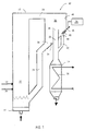
- FIGURE 1 illustrates a circulating fluidized bed (CFB) gasification reactor system 10 according to the present invention, including a circulating fluidized bed reactor 12 and a gas cooler 14.
- Gasification is practiced in the reactor 12 by introducing fluidizing gas through plenum 16 at the bottom of the reactor chamber 18.
- Solid fuel material is introduced into the reactor chamber 18 via an inlet 20 and solid bed material is introduced via inlet 22.
- the solid bed material may be an inert material such as sand, and may comprise additives, such as material active in the gasification process, e.g. limestone or other sulfur oxide reducing agents.
- the fuel material introduced at 20 is reacted (gasified in the case of FIGURE 1, but combusted or otherwise reacted in other reactor systems which also are within the scope of the invention) to produce an exhaust gas which is discharged from an outlet 24 adjacent the top of the reactor chamber 18 and connected to a cyclone separator 26.
- the cyclone separator comprises a gas outlet 28 forming the inlet end of a gas discharge 32 arranged to go through the bottom 34 of the separator 26.
- the gas discharge conduit 32 protrudes into the cyclone separator 26, so as to place the gas outlet at a distance above the bottom 34 and so as to form a center piece within the vortex chamber of the cyclone separator 26.
- Hot gas is introduced through reactor outlet 24 into the cyclone separator so as to form a vortex flow therein, whereby solid particles are separated and gather on the bottom 34.
- the solid material outlet 36 is connected through a solid material return conduit 38 with the bottom region of the reactor chamber 18, for recycling separated solid material into the reactor chamber.
- the gas produced during the reaction in reactor 18 and discharged through a gas outlet 24 therefrom includes in it entrained particulates, such as inert solid bed particles, additives and un-reacted fuel material, including some fine carbon material.
- particulates such as inert solid bed particles, additives and un-reacted fuel material, including some fine carbon material.
- the vast majority of the particles, particularly the large particles, are separated from the exhaust gas by the separator 26, and are returned by return conduit 38 to the lower part of the reactor chamber 18, as is conventional per se.
- the product gas which exhausts the separator 26 passes to the gas cooler 14.
- the exhaust gas from the reactor 18 and separator 26 has a temperature above 600°C, and the cooler 14 is typically designed to cool the gases to about 400°C.
- the gas cooler 14 includes a heat exchanger 30 formed of heat transfer surfaces, hot gas flowing on the outside of the heat transfer surfaces.
- the heat transfer surfaces may be made of water tubes, typically for producing steam to drive a steam turbine.
- Another heat exchanger or more may if desired be provided, connected to a turbine, other heat exchangers or the like.
- a fire-tube cooler in which hot gas flows inside a plurality of spaced tubes could be used.
- the space between the tubes is used as a conduit for heat transfer medium to extract heat from the gases.
- the surfaces are kept clean, or cleaned after accumulation of deposits, by introducing solid particles into the gas flow in, or just before, the cooler 14. This, for example, may be accomplished by injecting coarse particles using by-pass conduit 40, the coarse particles being provided from particles being separated from the gas in the cyclone separator 26. Such particles including e.g. sand, additives and/or un-reacted fuel.
- control may be automatic, e.g. in response to sensing of a decrease in cooling efficiency as a result of depositing or condensing or sticky substances.
- a second cyclone separator may be provided downstream of the gas cooler 14.
- the second separator may operate continuously, but is particularly necessary when particles are introduced (e.g. through by-pass conduit 40) to effect cleaning. Particles separated by the second separator may either be returned to the reactor 18 or may be disposed of.
- the thus cleaned product gas, discharged from the second separator may be filtered, and acted upon, or may be used directly, depending upon the desired use and the gas's composition.
- the by-pass conduit is controlled by a cover plate 42 being able to partly or wholly cover the inlet 44 into the by-pass conduit 40.
- the cover plate may be operated by a handle 46 by hand from outside the cyclone enclosure 48, or the cover plate 42 may be automatically operated by suitable automatic control means 50, such as conventional computer controller, for controlling the flow of particles introduced for cleaning.
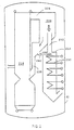
- FIGURE 2 illustrates a system substantially the same as that in FIGURE 1 same reference numbers as in FIGURE 1 are used preceded by a "2".
- the by-pass conduit 240 is connected to the return conduit 238 and solid particles are introduced directly into the gas cooler 214, not into the inlet conduit or center pipe 232.
- Several heat exchanger packages 230 are provided in the gas cooler. Fluidizing gas may be used to transport particles in the by-pass conduit.
- the reactor 218, cyclone 226 and gas cooler 214 are enclosed in a pressure vessel 52 for maintaining them at superatmospheric pressure.
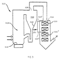
- FIGURE 3 illustrates a further system substantially the same as that in FIGURES 1 and 2 same reference numbers are used preceded by a "3".
- the particle separator is a conventional cyclone 326 having its gas outlet 328 in the upper part thereof. Solid particles are gathered from the wall 348 of the cyclone and led through a by-pass conduit 340 into the gas cooler 314.
- the by-pass conduit 340 is divided into two conduits 340' and 340'' introducing solid particles at different vertical levels in the gas cooler to mainly effect cleaning of different heat exchanger packages 330 and 330'.
Landscapes
- Chemical & Material Sciences (AREA)
- Engineering & Computer Science (AREA)
- Combustion & Propulsion (AREA)
- Oil, Petroleum & Natural Gas (AREA)
- Organic Chemistry (AREA)
- Chemical Kinetics & Catalysis (AREA)
- General Chemical & Material Sciences (AREA)
- Devices And Processes Conducted In The Presence Of Fluids And Solid Particles (AREA)
- Industrial Gases (AREA)
- Combined Means For Separation Of Solids (AREA)
Claims (16)
- Verfahren zum Betreiben eines Wirbelschichtreaktorsystems für das Reagierenlassen von Brennstoff, welches Reaktorsystem folgendes umfasst:
eine Wirbelschicht-Reaktorkammer, die einen Reaktorkammerauslass für während der Brennstoffreaktion produziertes Gas, einen mit dem Reaktorkammerauslass verbundenen Partikelabscheider zur Abscheidung von Feststoff aus aus der Reaktorkammer abgezogenem Gas, welcher Partikelabscheider einen Feststoffpartikelauslass und einen Gasauslass hat, und einen Gaskühler, der Kühlflächen hat und mit dem Gasauslass des Partikelabscheiders verbunden ist, welches Verfahren folgende Schritte umfasst:(a) Einführung von Feststoffpartikeln, Fluidisierungsmittel und Brennstoff in die Reaktorkammer, um eine Wirbelschicht darin zu bilden;(b) Reagierenlassen des Brennstoffmaterials innerhalb der Wirbelschicht, um Abgas zu produzieren, und Abzug des Abgases über den Reaktorkammerauslass;(c) Einführung des Abgases in den Partikelabscheider und Abtrennung von Feststoffpartikeln aus dem Gas in besagtem Partikelabscheider;(d) Ableitung von Gas aus dem Partikelabscheider durch den Gasauslass und eines ersten Stroms abgeschiedener Feststoffpartikel durch den Feststoffpartikelauslass und(e) Abkühlung des aus dem Abscheider in den Gaskühler abgezogenen Gases,
welches Verfahren durch folgende zusätzliche Schritte gekennzeichnet ist:(f) Verzweigung eines zweiten Feststoffpartikelstroms aus dem ersten Feststoffpartikelstrom vor oder nach dem Abzug des ersten Feststoffpartikelstroms aus dem Partikelabscheider;(g) Einführung des zweiten Feststoffpartikelstroms in das aus dem Abscheider abgezogene Gas während oder vor dem Schritt (e), so dass die Partikel Ablagerungen mechanisch von den Kühlflächen entfernen und sie dadurch reinigen, und(h) Entfernung der Partikel aus dem Gas nach dem Schritt (g). - Verfahren nach Anspruch 1, dadurch gekennzeichnet, dass die Schritte (f) und (g) nur mit beabstandeten Intervallen durchgeführt werden.
- Verfahren nach Anspruch 1, dadurch gekennzeichnet, dass die Schritte (f) und (g) kontinuierlich durchgeführt werden.
- Verfahren nach Anspruch 1, dadurch gekennzeichnet, dass der Schritt (g) durch Einführung von Partikeln ins Gas kurz vor dem Gaskühler durchgeführt wird.
- Verfahren nach Anspruch 1, dadurch gekennzeichnet, dass der Schritt (g) durch Einführung von Partikeln ins Gas im Gaskühler durchgeführt wird.
- Verfahren nach Anspruch 1, dadurch gekennzeichnet, dass der Reaktor ein Reaktor mit zirkulierender Wirbelschicht ist und einen Rückführkanal zwischen dem Partikelabscheider und dem unteren Teil der Reaktorkammer hat, welcher Rückführkanal normalerweise so funktioniert, dass er alle im Partikelabscheider abgeschiedenen Partikel empfängt, und dass die Schritte (f) und (g) derart durchgeführt werden, dass ein Teil der im Partikelabscheider abgeschiedenen Partikel periodisch in den Gaskühler eingeführt wird.
- Verfahren nach Anspruch 6, dadurch gekennzeichnet, dass ein Einlass zu dem den Partikelabscheider mit dem Gaskühler verbindenden Bypasskanal periodisch geöffnet wird, damit abgeschiedene Partikel durch den Bypasskanal in den Gaskühler fließen können.
- Verfahren nach Anspruch 1, dadurch gekennzeichnet, dass die Schritte (a) bis (g) bei einem überatmosphärischen Druck von ungefähr 2-50 durchgeführt werden.
- Verfahren nach Anspruch 1, dadurch gekennzeichnet, dass der Schritt (b) durchgeführt wird, um ein Gas bei einer Temperatur über 600 °C zu erzeugen, und der Schritt (e) durchgeführt wird, um das Gas auf ungefähr 400 °C abzukühlen.
- Es ist ein Reaktorsystem mit zirkulierender Wirbelschicht vorgesehen, das folgende Elemente umfasst:welches Reaktorsystem dadurch gekennzeichnet ist, dass es ferner Mittel (42,44) umfasst zur Abzweigung eines Feststoffpartikelstroms aus dem abgeschiedenen festen Bettmaterial und zur Einführung des verzweigten Bettmaterialstroms in den Gaskühler.Reaktorkammer (18) mit Wirbelschicht, die einen Bettmaterialeinlass (22, 20), einen Abgasauslass (24) und einen Fluidisierungsgaseinlass (16) hat;einen mit dem Abgasauslass verbundenen Zyklonabscheider (26), welcher Abscheider einen Gasauslass (28) und einen Partikelauslass (36) hat zur Rückführung von abgeschiedenem Bettmaterial in die Reaktorkammer;einen Rückführkanal (38), der den Partikelauslass (36) des Abscheiders mit der Reaktorkammer (18) verbindet, undeinen mit dem Abscheider-Gasauslass verbundenen Gaskühler (14), welcher Gaskühler Kühlflächen (30) hat,
- Reaktorsystem nach Anspruch 10, dadurch gekennzeichnet, dass ein den Reaktor (218), den Zyklon (226) und den Gaskühler (214) umschließendes Druckgefäß (52) vorgesehen ist, um sie auf überatmosphärischem Druck zu halten.
- Reaktorsystem nach Anspruch 10, dadurch gekennzeichnet, dass die Mittel zur Abzweigung eines Stroms festen Bettmaterials im Zyklonabscheider (26), in seinem Boden (34), eine Öffnung (44) umfassen, die mit einem Bypasskanal (40) verbunden ist zur Leitung von abgeschiedenem festem Bettmaterial vom Zyklonabscheider zum Gaskühler.
- Reaktorsystem nach Anspruch 12, dadurch gekennzeichnet, dass die Mittel zur Abzweigung eines Stroms festen Bettmaterials eine Abdeckplatte (42) umfassen, für das Zudecken der Öffnung (44) im Boden des Abscheiders.
- Reaktorsystem nach Anspruch 10, dadurch gekennzeichnet, dass die Mittel zur Abzweigung eines Stroms festen Bettmaterials einen Bypasskanal (240) umfassen, der den Rückführkanal (238) mit dem Gaskühler (214) verbindet.
- Reaktorsystem nach Anspruch 10, dadurch gekennzeichnet, dass der Zyklonabscheider (26) eine vertikale Wirbelkammer und einen mit dem Boden (34) des Zyklons verbundenen Gasauslass (28) umfasst.
- Reaktorsystem nach Anspruch 10, dadurch gekennzeichnet, dass der Zyklonabscheider (326) eine vertikale Wirbelkammer und einen mit seinem oberen Teil verbundenen Gasauslass (328) umfasst.
Applications Claiming Priority (1)
| Application Number | Priority Date | Filing Date | Title |
|---|---|---|---|
| PCT/FI1996/000100 WO1997031084A1 (en) | 1996-02-21 | 1996-02-21 | Method of operating a fluidized bed reactor system, and fluidized bed reactor system |
Publications (2)
| Publication Number | Publication Date |
|---|---|
| EP0889943A1 EP0889943A1 (de) | 1999-01-13 |
| EP0889943B1 true EP0889943B1 (de) | 2002-01-23 |
Family
ID=8556640
Family Applications (1)
| Application Number | Title | Priority Date | Filing Date |
|---|---|---|---|
| EP96903020A Expired - Lifetime EP0889943B1 (de) | 1996-02-21 | 1996-02-21 | Wirbelschichtreaktorsystem und methode zu seinem betrieb |
Country Status (8)
| Country | Link |
|---|---|
| US (1) | US6214065B1 (de) |
| EP (1) | EP0889943B1 (de) |
| JP (1) | JP2982977B2 (de) |
| AU (1) | AU4720296A (de) |
| DE (1) | DE69618819T2 (de) |
| DK (1) | DK0889943T3 (de) |
| ES (1) | ES2171648T3 (de) |
| WO (1) | WO1997031084A1 (de) |
Cited By (2)
| Publication number | Priority date | Publication date | Assignee | Title |
|---|---|---|---|---|
| TWI391610B (zh) * | 2009-02-27 | 2013-04-01 | Mitsubishi Heavy Ind Environment & Chemical Engineering Co Ltd | 循環型流體化床爐、具備循環型流體化床爐的處理系統、及循環型流體化床爐的運轉方法 |
| WO2025168667A1 (en) * | 2024-02-06 | 2025-08-14 | Borealis Gmbh | Integrated reactor system and process for simultaneously producing a mixture of hydrocarbons from a carbonaceous feedstock and recovering heat |
Families Citing this family (11)
| Publication number | Priority date | Publication date | Assignee | Title |
|---|---|---|---|---|
| FI112952B (fi) * | 2001-12-21 | 2004-02-13 | Foster Wheeler Energia Oy | Menetelmä ja laitteisto hiilipitoisen materiaalin kaasuttamiseksi |
| DE102004051477B4 (de) * | 2004-10-22 | 2008-10-02 | Alstom Technology Ltd. | Verfahren zur Regulierung der Feststoffumlaufmenge eines zirkulierenden Wirbelschichtreaktorsystems |
| DE102005005796A1 (de) * | 2005-02-09 | 2006-08-17 | Applikations- Und Technikzentrum Für Energieverfahrens-, Umwelt- Und Strömungstechnik (Atz-Evus) | Verfahren und Vorrichtung zur thermochemischen Umsetzung eines Brennstoffs |
| NL1030189C2 (nl) * | 2005-10-13 | 2007-04-16 | Stichting Energie | Inrichting en werkwijze voor het reinigen van een uit biomassa gevormd productgas. |
| WO2009149602A1 (zh) * | 2008-06-13 | 2009-12-17 | Peng Sigan | 一种海船排烟洗涤装置及洗涤方法 |
| US9757686B2 (en) | 2008-06-13 | 2017-09-12 | Sigan Peng | Ship flue gas scrubbing apparatus and method |
| US8196533B2 (en) * | 2008-10-27 | 2012-06-12 | Kentucky-Tennessee Clay Co. | Methods for operating a fluidized-bed reactor |
| US8821600B2 (en) * | 2011-11-30 | 2014-09-02 | Aerojet Rocketdyne Of De, Inc. | Dry bottom reactor vessel and method |
| ES2436844B1 (es) | 2013-09-23 | 2014-07-07 | Eqtec Iberia, S.L. | Procedimiento para la gasificaci�n de materiales sólidos orgánicos y reactor empleado |
| DE102017210044A1 (de) * | 2017-06-14 | 2018-12-20 | Thyssenkrupp Ag | Nachbehandlungsanordnung und Verfahren zum Nachbehandeln von zumindest Gasen stromab einer Wirbelschichtvergasung sowie Logikeinheit und Verwendung |
| EP4209710A1 (de) | 2022-01-10 | 2023-07-12 | ICMEA Srl leader of temporary association of companies ICMEA Srl - Tecnomec Engineering Srl - CNR IRSA | Wirbelbetteinheit |
Family Cites Families (6)
| Publication number | Priority date | Publication date | Assignee | Title |
|---|---|---|---|---|
| JPS57179289A (en) | 1981-04-28 | 1982-11-04 | Agency Of Ind Science & Technol | Recovering method of heat from gasified product of hydrocarbon |
| DE3724947A1 (de) * | 1987-07-28 | 1989-02-16 | Uhde Gmbh | Verfahren und vorrichtung zum kuehlen von rohgas aus einer partiellen oxidation von kohlenstoffhaltigem material |
| GB2232682A (en) * | 1989-05-31 | 1990-12-19 | Shell Int Research | Process for removal of flyslag deposits |
| US5281398A (en) | 1990-10-15 | 1994-01-25 | A. Ahlstrom Corporation | Centrifugal separator |
| US5269263A (en) * | 1992-09-11 | 1993-12-14 | Foster Wheeler Energy Corporation | Fluidized bed reactor system and method of operating same |
| DE69504524T2 (de) * | 1994-08-23 | 1999-04-15 | Foster Wheeler Energia Oy, Helsinki | Methode zum betreiben eines wirbelbettreaktorsystems, und ein solches system |
-
1996
- 1996-02-21 DK DK96903020T patent/DK0889943T3/da active
- 1996-02-21 ES ES96903020T patent/ES2171648T3/es not_active Expired - Lifetime
- 1996-02-21 US US09/117,141 patent/US6214065B1/en not_active Expired - Fee Related
- 1996-02-21 AU AU47202/96A patent/AU4720296A/en not_active Abandoned
- 1996-02-21 DE DE69618819T patent/DE69618819T2/de not_active Expired - Fee Related
- 1996-02-21 WO PCT/FI1996/000100 patent/WO1997031084A1/en not_active Ceased
- 1996-02-21 EP EP96903020A patent/EP0889943B1/de not_active Expired - Lifetime
- 1996-02-21 JP JP9529823A patent/JP2982977B2/ja not_active Expired - Fee Related
Cited By (2)
| Publication number | Priority date | Publication date | Assignee | Title |
|---|---|---|---|---|
| TWI391610B (zh) * | 2009-02-27 | 2013-04-01 | Mitsubishi Heavy Ind Environment & Chemical Engineering Co Ltd | 循環型流體化床爐、具備循環型流體化床爐的處理系統、及循環型流體化床爐的運轉方法 |
| WO2025168667A1 (en) * | 2024-02-06 | 2025-08-14 | Borealis Gmbh | Integrated reactor system and process for simultaneously producing a mixture of hydrocarbons from a carbonaceous feedstock and recovering heat |
Also Published As
| Publication number | Publication date |
|---|---|
| WO1997031084A1 (en) | 1997-08-28 |
| DK0889943T3 (da) | 2002-05-06 |
| ES2171648T3 (es) | 2002-09-16 |
| JPH11504381A (ja) | 1999-04-20 |
| DE69618819T2 (de) | 2002-08-22 |
| US6214065B1 (en) | 2001-04-10 |
| AU4720296A (en) | 1997-09-10 |
| DE69618819D1 (de) | 2002-03-14 |
| JP2982977B2 (ja) | 1999-11-29 |
| EP0889943A1 (de) | 1999-01-13 |
Similar Documents
| Publication | Publication Date | Title |
|---|---|---|
| US4464183A (en) | Heat recovery process in coal gasification | |
| US6214065B1 (en) | Method of operating a fluidized bed reactor system, and fluidized bed reactor system | |
| EP0689654B1 (de) | Wirbelbettreaktor mit rückführung der teilchen | |
| EP0777711B1 (de) | Methode zum betreiben eines wirbelbettreaktorsystems, und ein solches system | |
| EP0630684B1 (de) | Verfahren und Vorrichtung zur Behandlung oder zur Verwendung eines Heissgasstromes | |
| US4035170A (en) | Granular filter | |
| EP0762923B1 (de) | Verhinderung von aschebrückenbildung in keramischen filtern | |
| US4033117A (en) | Solid fuel fired gas turbine system having continuously regenerating granular filter | |
| EP0515878B1 (de) | Reinigung von heissen Hochdruckgasen | |
| US4412848A (en) | Heat recovery method from gasified products of hydrocarbon | |
| FI112952B (fi) | Menetelmä ja laitteisto hiilipitoisen materiaalin kaasuttamiseksi | |
| JP2000504991A (ja) | 高温ガス濾過装置 | |
| JP2969369B2 (ja) | 燃焼装置、特に、渦流層式燃焼装置 | |
| EP0595867B1 (de) | Verfahren zum entfernen von niederschlägen an den wänden der einlassrohrleitung eines gaskühlers sowie einlassrohrleitung für gaskühler mit gekühlter elastischer metallstruktur | |
| US5464528A (en) | FCC process and apparatus with upset tolerant third stage separator | |
| EP0177527B1 (de) | Zwei- oder mehrfacher reaktor | |
| US5567228A (en) | System for cooling and cleaning synthesized gas using ahot gravel bed | |
| EP0060044B1 (de) | Wirbelschichtverbrennung | |
| US5171542A (en) | Circulating fluidized bed reactor | |
| US5277151A (en) | Integral water-cooled circulating fluidized bed boiler system | |
| EP4209710A1 (de) | Wirbelbetteinheit | |
| WO2002086385A1 (en) | Waste heat boiler | |
| EP1712839B1 (de) | Verfahren zur wärmerückgewinnung und wärmerückgewinnungsvorrichtung | |
| US20020146362A1 (en) | Method of filtration and cleansing of high temperature combustible gases | |
| EP0074461A1 (de) | Abscheider mit gekühlter Wand |
Legal Events
| Date | Code | Title | Description |
|---|---|---|---|
| PUAI | Public reference made under article 153(3) epc to a published international application that has entered the european phase |
Free format text: ORIGINAL CODE: 0009012 |
|
| 17P | Request for examination filed |
Effective date: 19980625 |
|
| AK | Designated contracting states |
Kind code of ref document: A1 Designated state(s): DE DK ES FR SE |
|
| GRAG | Despatch of communication of intention to grant |
Free format text: ORIGINAL CODE: EPIDOS AGRA |
|
| RIC1 | Information provided on ipc code assigned before grant |
Free format text: 7C 10J 3/54 A, 7C 10J 3/56 B, 7C 10J 3/84 B |
|
| 17Q | First examination report despatched |
Effective date: 20010316 |
|
| GRAG | Despatch of communication of intention to grant |
Free format text: ORIGINAL CODE: EPIDOS AGRA |
|
| GRAG | Despatch of communication of intention to grant |
Free format text: ORIGINAL CODE: EPIDOS AGRA |
|
| GRAH | Despatch of communication of intention to grant a patent |
Free format text: ORIGINAL CODE: EPIDOS IGRA |
|
| GRAH | Despatch of communication of intention to grant a patent |
Free format text: ORIGINAL CODE: EPIDOS IGRA |
|
| GRAA | (expected) grant |
Free format text: ORIGINAL CODE: 0009210 |
|
| AK | Designated contracting states |
Kind code of ref document: B1 Designated state(s): DE DK ES FR SE |
|
| REF | Corresponds to: |
Ref document number: 69618819 Country of ref document: DE Date of ref document: 20020314 |
|
| REG | Reference to a national code |
Ref country code: DK Ref legal event code: T3 |
|
| ET | Fr: translation filed | ||
| REG | Reference to a national code |
Ref country code: ES Ref legal event code: FG2A Ref document number: 2171648 Country of ref document: ES Kind code of ref document: T3 |
|
| PLBE | No opposition filed within time limit |
Free format text: ORIGINAL CODE: 0009261 |
|
| STAA | Information on the status of an ep patent application or granted ep patent |
Free format text: STATUS: NO OPPOSITION FILED WITHIN TIME LIMIT |
|
| 26N | No opposition filed | ||
| PGFP | Annual fee paid to national office [announced via postgrant information from national office to epo] |
Ref country code: FR Payment date: 20050113 Year of fee payment: 10 |
|
| PGFP | Annual fee paid to national office [announced via postgrant information from national office to epo] |
Ref country code: DK Payment date: 20050114 Year of fee payment: 10 |
|
| PGFP | Annual fee paid to national office [announced via postgrant information from national office to epo] |
Ref country code: DE Payment date: 20050121 Year of fee payment: 10 |
|
| PGFP | Annual fee paid to national office [announced via postgrant information from national office to epo] |
Ref country code: SE Payment date: 20050124 Year of fee payment: 10 |
|
| PGFP | Annual fee paid to national office [announced via postgrant information from national office to epo] |
Ref country code: ES Payment date: 20050204 Year of fee payment: 10 |
|
| PG25 | Lapsed in a contracting state [announced via postgrant information from national office to epo] |
Ref country code: SE Free format text: LAPSE BECAUSE OF NON-PAYMENT OF DUE FEES Effective date: 20060222 Ref country code: ES Free format text: LAPSE BECAUSE OF NON-PAYMENT OF DUE FEES Effective date: 20060222 |
|
| PG25 | Lapsed in a contracting state [announced via postgrant information from national office to epo] |
Ref country code: DK Free format text: LAPSE BECAUSE OF NON-PAYMENT OF DUE FEES Effective date: 20060228 |
|
| PG25 | Lapsed in a contracting state [announced via postgrant information from national office to epo] |
Ref country code: DE Free format text: LAPSE BECAUSE OF NON-PAYMENT OF DUE FEES Effective date: 20060901 |
|
| REG | Reference to a national code |
Ref country code: DK Ref legal event code: EBP |
|
| EUG | Se: european patent has lapsed | ||
| REG | Reference to a national code |
Ref country code: FR Ref legal event code: ST Effective date: 20061031 |
|
| REG | Reference to a national code |
Ref country code: ES Ref legal event code: FD2A Effective date: 20060222 |
|
| PG25 | Lapsed in a contracting state [announced via postgrant information from national office to epo] |
Ref country code: FR Free format text: LAPSE BECAUSE OF NON-PAYMENT OF DUE FEES Effective date: 20060228 |