EP0889741B2 - Substrate for the controlled release of volatile substances - Google Patents
Substrate for the controlled release of volatile substances Download PDFInfo
- Publication number
- EP0889741B2 EP0889741B2 EP97915431A EP97915431A EP0889741B2 EP 0889741 B2 EP0889741 B2 EP 0889741B2 EP 97915431 A EP97915431 A EP 97915431A EP 97915431 A EP97915431 A EP 97915431A EP 0889741 B2 EP0889741 B2 EP 0889741B2
- Authority
- EP
- European Patent Office
- Prior art keywords
- support body
- body according
- recesses
- volatile substances
- constructed
- Prior art date
- Legal status (The legal status is an assumption and is not a legal conclusion. Google has not performed a legal analysis and makes no representation as to the accuracy of the status listed.)
- Expired - Lifetime
Links
Images


Classifications
-
- A—HUMAN NECESSITIES
- A01—AGRICULTURE; FORESTRY; ANIMAL HUSBANDRY; HUNTING; TRAPPING; FISHING
- A01M—CATCHING, TRAPPING OR SCARING OF ANIMALS; APPARATUS FOR THE DESTRUCTION OF NOXIOUS ANIMALS OR NOXIOUS PLANTS
- A01M1/00—Stationary means for catching or killing insects
- A01M1/20—Poisoning, narcotising, or burning insects
- A01M1/2022—Poisoning or narcotising insects by vaporising an insecticide
- A01M1/2027—Poisoning or narcotising insects by vaporising an insecticide without heating
- A01M1/2055—Holders or dispensers for solid, gelified or impregnated insecticide, e.g. volatile blocks or impregnated pads
-
- A—HUMAN NECESSITIES
- A61—MEDICAL OR VETERINARY SCIENCE; HYGIENE
- A61L—METHODS OR APPARATUS FOR STERILISING MATERIALS OR OBJECTS IN GENERAL; DISINFECTION, STERILISATION OR DEODORISATION OF AIR; CHEMICAL ASPECTS OF BANDAGES, DRESSINGS, ABSORBENT PADS OR SURGICAL ARTICLES; MATERIALS FOR BANDAGES, DRESSINGS, ABSORBENT PADS OR SURGICAL ARTICLES
- A61L9/00—Disinfection, sterilisation or deodorisation of air
- A61L9/015—Disinfection, sterilisation or deodorisation of air using gaseous or vaporous substances, e.g. ozone
- A61L9/04—Disinfection, sterilisation or deodorisation of air using gaseous or vaporous substances, e.g. ozone using substances evaporated in the air without heating
- A61L9/042—Disinfection, sterilisation or deodorisation of air using gaseous or vaporous substances, e.g. ozone using substances evaporated in the air without heating with the help of a macromolecular compound as a carrier or diluent
-
- A—HUMAN NECESSITIES
- A61—MEDICAL OR VETERINARY SCIENCE; HYGIENE
- A61L—METHODS OR APPARATUS FOR STERILISING MATERIALS OR OBJECTS IN GENERAL; DISINFECTION, STERILISATION OR DEODORISATION OF AIR; CHEMICAL ASPECTS OF BANDAGES, DRESSINGS, ABSORBENT PADS OR SURGICAL ARTICLES; MATERIALS FOR BANDAGES, DRESSINGS, ABSORBENT PADS OR SURGICAL ARTICLES
- A61L9/00—Disinfection, sterilisation or deodorisation of air
- A61L9/015—Disinfection, sterilisation or deodorisation of air using gaseous or vaporous substances, e.g. ozone
- A61L9/04—Disinfection, sterilisation or deodorisation of air using gaseous or vaporous substances, e.g. ozone using substances evaporated in the air without heating
- A61L9/046—Disinfection, sterilisation or deodorisation of air using gaseous or vaporous substances, e.g. ozone using substances evaporated in the air without heating with the help of a non-organic compound
-
- A—HUMAN NECESSITIES
- A61—MEDICAL OR VETERINARY SCIENCE; HYGIENE
- A61L—METHODS OR APPARATUS FOR STERILISING MATERIALS OR OBJECTS IN GENERAL; DISINFECTION, STERILISATION OR DEODORISATION OF AIR; CHEMICAL ASPECTS OF BANDAGES, DRESSINGS, ABSORBENT PADS OR SURGICAL ARTICLES; MATERIALS FOR BANDAGES, DRESSINGS, ABSORBENT PADS OR SURGICAL ARTICLES
- A61L9/00—Disinfection, sterilisation or deodorisation of air
- A61L9/015—Disinfection, sterilisation or deodorisation of air using gaseous or vaporous substances, e.g. ozone
- A61L9/04—Disinfection, sterilisation or deodorisation of air using gaseous or vaporous substances, e.g. ozone using substances evaporated in the air without heating
- A61L9/12—Apparatus, e.g. holders, therefor
Definitions
- the invention relates to a carrier body for the controlled release of volatile substances, which are used for the disinfection or deodorization of rooms or for similar purposes, which generally serve the room air freshening or improving.
- Fragrance or drug donors which are assigned to the so-called “slow-release” systems or the so-called “controlled-release” systems depending on their mode of operation and essentially to the controlled release of a reservoir of fragrances or active ingredients by using different physical or chemical properties are based, find today not only in the domestic and especially in the sanitary sector or in the interior of vehicles, but increasingly in industry and in agriculture and forestry wide application fields.
- they are used for storage and delivery of volatile substances with deodorizing function, resulting in a refreshment or improvement of the room air result.
- Previously used carrier materials have proved to be disadvantageous insofar as the stored substances are released by them normally too fast or too slow.
- the fragrance or active ingredient is introduced into a plastic container which is closed with a cellulose membrane.
- This membrane has no defined pore structure, so that the substance delivery is difficult to control. In fluctuating air movements, the membrane can dry out very quickly; the supply of stored material then stagnates.
- An aged membrane also has an undesirable selective effect, so that no longer the entire fragrance or active substance range is released, that is, the composition of the fragrances or active ingredients changes over time.
- Carrier bodies made of ceramic have only low pore volumes of up to 40% and have only a small proportion of open pores.
- the substances to be vaporized can be stored here predominantly on the outer surface, so that only small amounts of substrate per unit of space can be applied.
- the minerals unavoidably contained in ceramics can lead to a selective fixation of flavorings.
- the German patent DE 44 17 739 describes in a similar context the use of a porous body made of open-pored sintered glass for the storage and controlled release of vaporizable substances.
- the body preferably has a pore volume of 30% to 85% and an average pore size of 10 ⁇ m to 350 ⁇ m.
- slow-release systems have several disadvantages and shortcomings. So they are generally inert, that is, in closed rooms passes due to the slow release of the active ingredients some time until the desired drug concentration is reached. However, this is in clear contradiction to the aim, for example, of scenting residential or business premises, to perceive the fragrance immediately after use. Even with the use of insecticides in enclosed spaces, it is desirable to achieve the necessary insecticidal concentration as quickly as possible in order to use no more active ingredient than absolutely necessary. Subsequently, the drug concentration should be maintained over a period of time.
- the "slow-release” systems further a certain inefficiency can not be denied, as they permanently evaporate the active ingredients, that is to release even in times when there is no need in this regard.
- the known "slow-release” systems even today, the ever-increasing demands for environmental protection in any way taken into account, since the "slow-release” systems require a high packaging cost and are not refillable in most cases.
- a portion of the fragrance or active substance can be released immediately if required by application to one or more sides of the carrier, so that metering devices As a rule, they are characterized by an immediate effect, which so far, however, often only lasted for a relatively short period of time.
- a technique often used here for the purpose of continuously dispensing fragrances or active substances consists of dispensing from an atomizer a certain amount of fragrance or active substance and spraying it into a carrier material, cellulosic cardboard, felt being the carrier material according to the state of the art or fleece were proposed. These materials are commonly used in "slow-release” systems and absorb the fragrance or drug almost completely.
- an aerosol container actuation cap which, when applied to the aerosol container in place of the normal removable cap, permits easy actuation of the fluid release valve to spray the fluid, with the user's hand against contact with the fluid and wherein the spraying is carried out in such a way that a portion of the sprayed liquid is radiated freely into the air in the usual way, while the rest of the liquid impregnates an absorbent material from which it can evaporate, in this way both a To get fast as well as a supportive action for chemicals of the liquid.
- the in the DE 23 31 981 disclosed actuator cap for aerosol containers is in this case intended in particular for use in aerosol containers, which have a valve which emits the liquid content in the axial direction and can be actuated by finger pressure.
- a volatile substance delivery device in particular an air freshener, which comprises an aerosol pressure vessel containing the substances to be delivered together with a propellant.
- the actuation of the dispensing valve of the container is effected by a hollow push-button, which has at least one openwork wall portion and which cooperates in the longitudinal direction with the dispensing head, which is connected to the movable part of the dispensing valve.
- the push button houses at least one absorbing element which is impregnated with the substances discharged from the pressure vessel through at least one outlet opening in the dispensing head and which are thrown into the interior of the push button and against a baffle and then fall onto the absorbent element ,
- cellulose bodies Another disadvantage of cellulose bodies is their swellability. At higher humidity, the cellulosic body can break up in layers, whereby the subsequent excessive access of air shortens the duration of action and changes the desired active substance concentration in the room air. Thus, it can lead to deformations and discoloration in the cellulose bodies, which affects the aesthetic impression and thus of course the saleability of products with such carriers sustainable.
- the publication GB 286,862 discloses a volatile deodorizing or disinfecting block externally provided with surface depressions, such as grooves, so that the surface is substantially increased in proportion to the volume. From the publication GB 286,862 However, it does not explicitly state that the volatile substances can be metered onto the carrier body, since, for example, a disinfectant block of solid naphthalene is described. Furthermore, goes out of the document GB 286,862 does not explicitly state that the carrier material must be chemically inert.
- a support body for dosing devices such as sprays, spray systems, dropper bottles or possibly also brush bottles, especially for use in rooms, for receiving, storage and controlled release of portions of volatile substances (fragrance or active ingredients), so that on the one hand an immediate fragrance effect is ensured with good and uniform dosing, on the other hand, however, over a long period of time allows.
- the present invention aims at a carrier body which absorbs the fragrance or active ingredients to be applied only when needed and in one portion, without absorbing them.
- the active ingredient combination should be controlled by the carrier body as a function of the temperature at a constantly high rate, controlled and completely released.
- a further object of the invention is to provide a carrier body which guarantees this continuous evaporation or sublimation of the stored substances in unchanged composition.
- the material of the carrier body is metal or a metal alloy with a thermal conductivity in the range of at least 10 1 W ⁇ m -1 ⁇ K -1 to at most 40 ⁇ 10 1 W ⁇ m -1 ⁇ K -1 , wherein it is preferably in the metal alloy is stainless steel with a thermal conductivity in the range of 1.5 ⁇ 10 1 W ⁇ m -1 ⁇ K -1 . Accordingly, in a surprisingly simple and yet extremely effective manner, one benefits from the fact that a higher the thermal conductivity of the material constituting the carrier body, the longer a certain amount of volatile substances can be perceived at room temperature. With respect to the present invention, this means that the more volatile the substances, the higher the thermal conductivity of the carrier material should be, in order to achieve an extension of the scent perception in comparison with a direct application into the air.
- the carrier body according to the invention in the form of at least one support plate is formed with the largest possible surface.
- the support body is formed in the form of two or more support plates which are arranged parallel to each other.
- the carrier body can also be designed in the form of two or more carrier plates, which are arranged in lateral offset and / or in angular offset from one another.
- the support plate may be formed in a curved shape, in particular in the form of a cylinder wall, a conical shell or a spherical shell.
- Preferred embodiments of the carrier body according to the invention include that the carrier plate has a surface area in the range of at least 2 cm 2 to at most 500 cm 2 and a thickness in the range of at least 0.1 mm to at most 2 mm.
- the recesses are at least partially formed as openings, wherein the ratio of surface area to volume of the carrier body is expediently at most 500 ⁇ 10 2 m -1 .
- the recesses or openings are arranged at regular intervals.
- the recesses or openings in this case formed so that the carrier body has the shape of a gauze, a fabric, a grid, a net or a screen, or the recesses or openings are in the form of grooves of any width, so is an additional Extension of the scent perception achieved.
- the carrier body is designed in the form of at least one carrier plate with the largest possible surface area, the depth of the depressions or openings in the carrier plate is at most equal to the thickness of the carrier plate in a particularly preferred development of the carrier body according to the invention.
- the diameter of the recesses or openings advantageously moves in the range of at least 0.2 mm to at most 1 mm, while the center distance between adjacent recesses or openings in the range of at least 0.2 mm to at most 60 mm moves.
- the recesses or openings arranged in the carrier body are at most completely filled with the volatile substances (fragrances or active substances) in accordance with the above-mentioned dimensioning, convection which is desirable in the present field of application of the carrier body according to the invention is sufficiently ensured, the volatile substances are vaporizable in all directions.
- the carrier body according to the invention As can already be seen from the above statements, its physical structure is of particular importance for a successful use of the carrier body according to the invention. For this reason, the areas of the surface of the support plate having recesses or perforations occupy at most 60% of the entire surface of the support plate.
- An extension of the scent perception is also achieved by at least sectionally or locally coating the carrier body with at least one medium which increases the adhesion of the volatile substances in a suitable manner.
- the medium is preferably light and / or oxidation resistant and advantageously odorless.
- the medium can be, for example, a fixator which is applied to the carrier body, for example by an atomizer, or oil.
- the carrier body when applying the volatile substances from a metering device on the carrier body expediently a distance of at most 20 cm from the metering device.
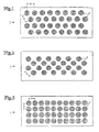
- Fig. 1 to 12 represent schematic views of ten embodiments of a carrier body according to the invention for receiving, storing and regulated delivery of volatile substances (scents or active ingredients), which are metered onto the carrier body can be applied.
- the carrier body enables an immediate odor effect with simultaneous meterability over a long period of time, which guarantees continuous evaporation or sublimation of the stored substances in unchanged composition over a long period of time compared to a direct application of a dose into the air.
- the fragrance impression thus remains on the carrier body for a large period of time without experiencing an undesirable change.
- the medium is light and oxidation resistant and odorless.
- the medium can be, for example, a fixator which is applied to the carrier body, for example by an atomizer, or oil.
- fixatives are substances which are able to give the scent of the volatile substances increased stability and to slow down and harmonize the evaporation of the individual scent components in such a way that the scent character remains reasonably constant during the evaporation period.
- the fixatives themselves are usually low volatility and high-boiling and can be fragrant or fragrance-free.
- each of the carrier body shown has recesses or openings 2 for receiving and storing the volatile substances.
- its physical structure is of particular importance for a successful use of the carrier body according to the invention.
- those in the Fig. 1 to 12 formed carrier body according to the invention, so that the ratio of surface area to volume in these carrier bodies is at least 1 ⁇ 10 2 m -1 .
- the upper limit for the ratio of surface area to volume in these carrier bodies is 500 ⁇ 10 2 m -1 .
- the surface to volume ratio preferably ranges from 5 ⁇ 10 2 m -1 to 100 ⁇ 10 2 m -1 .
- the areas of the surface (s) of the carrier body, which have recesses or perforations 2 take in the Fig. 1 to 12 at most 60% of the total surface of the carrier body.
- the carrier body in this case has a surface in the range of at least 2 cm 2 to at most 500 cm 2 and a thickness (D) in the range of at least 0.1 mm to at most 2 mm.
- the carrier body according to the invention consist of a material which is chemically inert to the volatile substances and / or their solvents.
- This material comprises metal or a metal alloy having a thermal conductivity in the range of at least 10 1 W ⁇ m -1 ⁇ K -1 to at most 40 ⁇ 10 1 W ⁇ m -1 ⁇ K -1 , wherein the metal alloy is stainless steel a thermal conductivity in the range of 1.5 ⁇ 10 1 W ⁇ m -1 ⁇ K -1 can act.
- the support body according to the invention is in each case formed in the form of a support plate 1 with the largest possible outer surface.
- the recesses or openings 2 in the support plate 1 are each configured at regular intervals in the form of circular holes, the diameter of which varies in the range of at least 0.2 mm to at most 1 mm, while their center distance A in the range of at least 0th , 2 mm to a maximum of 60 mm.
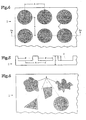
- FIG. 4 an enlarged section of the in Fig. 3 illustrated schematic plan view of the third embodiment of a carrier body according to the invention.
- Fig. 5 shows a side sectional view of the in Fig. 4 illustrated enlarged section of the schematic plan view of the third embodiment of a carrier body according to the invention along the section line S4-S4 Fig. 4 , where in Fig. 5 the depth T of the depressions or openings 2 is equal to half the thickness D of the support plate 1.
- each selected dimensions as a carrier material for example polyethylene (PE) having a thermal conductivity in the range of 1.2 ⁇ 10 -1 W ⁇ m -1 ⁇ K -1 , not according to the invention as shown by the arrangement of the holes shown an extension of the scent perception of half Hour to nine hours, that is by a factor of 18 observed.
- PE polyethylene
- the diameter ⁇ of the holes arranged in the support plate 1 also depends on the type of application of the volatile substance: If the volatile substances are applied, for example from a spray can to the support plate 1, the holes should have a diameter ⁇ have on the order of about 0.2 mm, while for the application with mechanical atomizers hole diameter ⁇ in the range of about 0.6 mm cause convincing results. In any case, the upper limit for the hole diameter ⁇ is given by the proportion of passing droplets. Although as many droplets as possible should adhere to the carrier plate 1, they should not form a closed film. In this case, the holes arranged in the support plate 1 should not be completely filled with the volatile substances in accordance with the dimensions listed above, so that sufficient convection is provided for the convection desired in the present field of application of the support body according to the invention.
- Fig. 6 shows a schematic plan view of a fourth embodiment of a carrier body according to the invention for the controlled release of volatile substances, are arranged in the irregularly shaped depressions or openings 2 in the support plate 1 at irregular intervals.
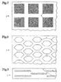
- the recesses or openings 2 in the support plate 1 can also be formed so that the support plate 1 has the shape of a gauze, a fabric, a grid, a net or a screen.
- the recesses or openings 2 are formed so that the support plate 1 in the form of a grid with square structure ( Fig. 7 ) or with honeycomb structure ( Fig. 8 ) having.
- Fig. 9 shows a schematic plan view of a seventh embodiment of a carrier body according to the invention for the controlled release of volatile substances, wherein the recesses or openings 2 are formed in the form of grooves through which, as through the square recesses of Fig. 7 and the honeycomb openings of the Fig. 8 , an additional extension of the scent perception is achieved.
- Fig. 10 shows a schematic view of an eighth embodiment of a carrier body according to the invention for the controlled release of volatile substances.
- This support body is in the form of four support plates 1, which are arranged parallel to each other and not only connected to each other by connecting means 5, but also stabilized in this position and supported by the connecting means 5.
- FIG. 11 shown schematic view of a ninth embodiment of a carrier body according to the invention for the controlled release of volatile substances.
- This support body is in the form of three support plates 1, which are arranged in lateral offset from one another and not only connected to each other by connecting means 5, but also stabilized in this position and supported by the connecting means 5.
- Fig. 12 shows a schematic plan view of a tenth embodiment of a carrier body according to the invention for the controlled release of volatile substances.
- This carrier body is in the form of two of the Fig. 1 formed support plates 1, which in angular displacement, in the example shown the Fig. 12 are arranged at right angles in angular displacement, to each other and not only connected to each other by angular connection means 5, but also stabilized in this position and are supported by the connecting means 5. It goes without saying that the angular displacement can also take any value other than 90 °.
- Fig. 13 shows a room freshener with an eleventh embodiment of a carrier body according to the invention for the controlled release of volatile substances.
- An essentially arbitrarily configurable vessel 3 is filled with liquid fragrances or active ingredients, the dosage of the liquid fragrances or active substances being effected by a metering device 4 such as an atomizer.
- the carrier plate 1 according to the invention which is intended for receiving and evaporation of the active ingredient portion, formed in a curved shape; It is made of stainless steel, is broken through and is mounted concentrically around the metering device 4 in the form of a cylinder wall, wherein the carrier plate 1 has a distance of at most 20 cm from the metering device 4 when applying the volatile substances.
- the support plate 1 could of course also be in the form of, for example, a conical shell or a spherical shell.
Abstract
Description
Die Erfindung bezieht sich auf einen Trägerkörper zur geregelten Abgabe flüchtiger Substanzen, wobei diese zur Desinfektion bzw. Desodorierung von Räumen oder zu ähnlichen Zwecken, die allgemein der Raumlufterfrischung oder -verbesserung dienen, eingesetzt werden.The invention relates to a carrier body for the controlled release of volatile substances, which are used for the disinfection or deodorization of rooms or for similar purposes, which generally serve the room air freshening or improving.
Duft- bzw. Wirkstoffspender, die abhängig von ihrer Funktionsweise den sogenannten "Slow-Release"-Systemen oder den sogenannten "Controlled-Release"-Systemen zuzuordnen sind und im wesentlichen auf der geregelten Freisetzung eines Reservoirs von Duft- bzw. Wirkstoffen durch Nutzung verschiedener physikalischer bzw. chemischer Eigenschaften basieren, finden heutzutage nicht nur im häuslichen und hier besonders im sanitären Bereich oder im Innenraum von Fahrzeugen, sondern in zunehmendem Maße auch in der Industrie sowie in der Land- und Forstwirtschaft breite Anwendungsfelder. Durch die Speicherung und Abgabe flüchtiger Substanzen mit desinfizierender Wirkung dienen sie beispielsweise der Vernichtung von Ungeziefer. Gleichfalls werden sie zur Speicherung und Abgabe flüchtiger Substanzen mit desodorierender Funktion verwendet, was eine Erfrischung bzw. Verbesserung der Raumluft zur Folge hat.Fragrance or drug donors, which are assigned to the so-called "slow-release" systems or the so-called "controlled-release" systems depending on their mode of operation and essentially to the controlled release of a reservoir of fragrances or active ingredients by using different physical or chemical properties are based, find today not only in the domestic and especially in the sanitary sector or in the interior of vehicles, but increasingly in industry and in agriculture and forestry wide application fields. By storing and dispensing volatile substances with a disinfecting effect they serve, for example, the destruction of vermin. Likewise, they are used for storage and delivery of volatile substances with deodorizing function, resulting in a refreshment or improvement of the room air result.
Bislang eingesetzte Trägermaterialien haben sich hierbei insofern als nachteilig erwiesen, als die gespeicherten Substanzen durch sie im Normalfall zu schnell oder zu langsam abgegeben werden. In einer verbreiteten Variante wird beispielsweise der Duft- bzw. Wirkstoff in ein Kunststoffbehältnis eingebracht, das mit einer Cellulosemembran verschlossen wird. Diese Membran weist keine definierte Porenstruktur auf, so daß die Stoffabgabe nur schwer geregelt werden kann. Bei schwankenden Luftbewegungen kann die Membran sehr schnell austrocknen; der Nachschub an gespeichertem Stoff stagniert dann. Eine gealterte Membran weist weiterhin eine unerwünschte selektive Wirkung auf, so daß nicht mehr die gesamte Duft- bzw. Wirkstoffpalette freigesetzt wird, das heißt die Zusammensetzung der Duft- bzw. Wirkstoffe ändert sich im Laufe der Zeit.Previously used carrier materials have proved to be disadvantageous insofar as the stored substances are released by them normally too fast or too slow. In a common variant, for example, the fragrance or active ingredient is introduced into a plastic container which is closed with a cellulose membrane. This membrane has no defined pore structure, so that the substance delivery is difficult to control. In fluctuating air movements, the membrane can dry out very quickly; the supply of stored material then stagnates. An aged membrane also has an undesirable selective effect, so that no longer the entire fragrance or active substance range is released, that is, the composition of the fragrances or active ingredients changes over time.
Eine einfachere Möglichkeit zur Speicherung und Abgabe von Duft- bzw. Wirkstoffen besteht in der Verwendung poröser Körper, bei denen sich der Duft- bzw. Wirkstoff in den Poren des porösen Körpers befindet und aus diesen Poren heraus verdunstet.An easier way to store and deliver fragrances or active ingredients is to use porous bodies in which the fragrance or active ingredient is in the pores of the porous body and evaporates out of these pores.
Trägerkörper aus Keramik weisen nur niedrige Porenvolumina bis zu 40 % auf und verfügen nur über einen geringen Anteil offener Poren. Die zu verdampfenden Stoffe können hier überwiegend auf der äußeren Oberfläche gespeichert werden, so daß nur geringe Substratmengen pro Raumeinheit aufgebracht werden können. Ebenfalls können die in Keramiken unvermeidbar enthaltenen Mineralstoffe zu einer selektiven Fixierung von Aromastoffen führen. Die
Für eine nachhaltige und dauerhafte Wirkung von "Slow-Release"-Systemen, bei denen eine Duft- bzw. Wirkstoffe abgebende Einheit fortwährend mit zu verflüchtigender Substanz versorgt wird, ist es von großer Bedeutung, daß die Verdunstung (= sich unterhalb des Siedepunkts einer Substanz vollziehender Übergang vom flüssigen in den gasförmigen Aggregatzustand) bzw. die Sublimation (= direkter Übergang einer Substanz vom festen in den gasförmigen Aggregatzustand, ohne daß der normalerweise dazwischenliegende flüssige Aggregatzustand angenommen wird) die Duft- bzw. Wirkstoffe kontinuierlich über einen längeren Zeitraum hinweg, das heißt je nach Einsatzgebiet mindestens einige Stunden lang, möglichst gleichmäßig mit konstanter Konzentration und mit konstanter Zusammensetzung abgibt. Hierbei ist jedoch eine gezielte Regelung der Abgabe der Duft- bzw. Wirkstoffe nur schwer, in manchen Fällen sogar überhaupt nicht möglich.For a sustained and lasting effect of "slow-release" systems, in which a fragrance or drug-releasing unit is constantly supplied with substance to be volatilized, it is of great importance that the evaporation (= below the boiling point of a substance enforcing transition from the liquid to the gaseous state of matter) or the sublimation (= direct transition of a substance from the solid to the gaseous state, without the normally intervening liquid state is assumed) the fragrances or active ingredients continuously over a longer period of time, the means depending on the application at least a few hours, as evenly as possible with a constant concentration and with a constant composition gives off. Here, however, a targeted regulation of the delivery of fragrances or active ingredients is difficult, in some cases even not possible.
Dementsprechend weisen "Slow-Release"-Systeme diverse Nachteile und Unzulänglichkeiten auf. So sind sie im allgemeinen reaktionsträge, das heißt in geschlossenen Räumen vergeht aufgrund der langsamen Freisetzung der Wirkstoffe einige Zeit, bis die angestrebte Wirkstoffkonzentration erreicht ist. Dies steht jedoch in deutlichem Widerspruch zu dem Ziel, beispielsweise bei der Beduftung von Wohn- oder Geschäftsräumen den Duft unmittelbar nach der Anwendung wahrzunehmen. Auch bei der Anwendung von Insektiziden in geschlossenen Räumen ist es wünschenswert, die notwendige insektizide Konzentration möglichst schnell zu erzielen, um nicht mehr Wirkstoff als unbedingt notwendig einsetzen zu müssen. Anschließend soll die Wirkstoffkonzentration über einen bestimmten Zeitraum aufrechterhalten werden.Accordingly, slow-release systems have several disadvantages and shortcomings. So they are generally inert, that is, in closed rooms passes due to the slow release of the active ingredients some time until the desired drug concentration is reached. However, this is in clear contradiction to the aim, for example, of scenting residential or business premises, to perceive the fragrance immediately after use. Even with the use of insecticides in enclosed spaces, it is desirable to achieve the necessary insecticidal concentration as quickly as possible in order to use no more active ingredient than absolutely necessary. Subsequently, the drug concentration should be maintained over a period of time.
Im allgemeinen ist den "Slow-Release"-Systemen des weiteren eine gewisse Ineffizienz nicht abzusprechen, da sie die Wirkstoffe permanent verdunsten, das heißt auch in Zeiten freisetzen, in denen gar kein diesbezüglicher Bedarf besteht. Darüber hinaus wird durch die bekannten "Slow-Release"-Systeme auch den heutzutage stetig ansteigenden Anforderungen an den Umweltschutz in keinster Weise Rechnung getragen, da die "Slow-Release"-Systeme einen hohen Verpackungsaufwand erfordern und in den meisten Fällen nicht wiederauffüllbar sind.In general, the "slow-release" systems further a certain inefficiency can not be denied, as they permanently evaporate the active ingredients, that is to release even in times when there is no need in this regard. In addition, by the known "slow-release" systems even today, the ever-increasing demands for environmental protection in any way taken into account, since the "slow-release" systems require a high packaging cost and are not refillable in most cases.
Im Gegensatz zu den "Slow-Release"-Systemen kann bei der Verwendung von Dosiereinrichtungen wie etwa Sprays, Zerstäubersystemen, Tropfflaschen oder gegebenenfalls auch Pinselflaschen eine Portion des Duft- bzw. Wirkstoffs bei Bedarf durch Aufbringen auf eine oder mehrere Trägerseiten sofort freigesetzt werden, so daß Dosiereinrichtungen im Regelfall durch eine unmittelbare Wirkung charakterisiert sind, die bislang allerdings oft nur für eine relativ kurze Zeitspanne vorhielt.In contrast to the "slow-release" systems, when using dosing devices such as sprays, atomizer systems, dropper bottles or optionally also brush bottles, a portion of the fragrance or active substance can be released immediately if required by application to one or more sides of the carrier, so that metering devices As a rule, they are characterized by an immediate effect, which so far, however, often only lasted for a relatively short period of time.
Eine hierbei zum Zwecke der kontinuierlichen Abgabe von Duft- bzw. Wirkstoffen vielfach verwendete Technik besteht darin, aus einem Zerstäuber eine bestimmte Menge eines Duft- bzw. Wirkstoffs abzugeben und in ein Trägermaterial zu sprühen, wobei als Trägermaterial nach dem Stand der Technik Cellulosekarton, Filz oder Vlies vorgeschlagen wurden. Diese Materialien werden üblicherweise in "Slow-Release"-Systemen verwendet und saugen den Duft- bzw. Wirkstoff nahezu vollständig auf.A technique often used here for the purpose of continuously dispensing fragrances or active substances consists of dispensing from an atomizer a certain amount of fragrance or active substance and spraying it into a carrier material, cellulosic cardboard, felt being the carrier material according to the state of the art or fleece were proposed. These materials are commonly used in "slow-release" systems and absorb the fragrance or drug almost completely.
So offenbart die
In der
Aus der
Vorstehend genannten Druckschriften
Ein weiterer Nachteil der Cellulosekörper besteht in der Quellbarkeit derselben. Bei höherer Luftfeuchtigkeit kann der Cellulosekörper schichtweise aufbrechen, wobei der dann folgende übermäßige Luftzutritt die Wirkungsdauer verkürzt und die erwünschte Wirkstoffkonzentration in der Raumluft verändert. Somit kann es bei den Cellulosekörpern zu Verformungen und zu Verfärbungen kommen, was den ästhetischen Eindruck und damit natürlich auch die Verkaufsfähigkeit von Produkten mit derartigen Trägern nachhaltig beeinträchtigt.Another disadvantage of cellulose bodies is their swellability. At higher humidity, the cellulosic body can break up in layers, whereby the subsequent excessive access of air shortens the duration of action and changes the desired active substance concentration in the room air. Thus, it can lead to deformations and discoloration in the cellulose bodies, which affects the aesthetic impression and thus of course the saleability of products with such carriers sustainable.
Festzuhalten bleibt also, daß die bislang bei "Slow-Release"-Systemen eingesetzten Trägermaterialien aus Cellulosefasern bei den in den Druckschriften
Aus dem deutschen Gebrauchsmuster
Die Druckschrift
Festzustellen ist schließlich, daß weder im deutschen Gebrauchsmuster
Ausgehend von den vorstehend geschilderten Unzulänglichkeiten liegt der vorliegenden Erfindung die Aufgabe zugrunde, einen Trägerkörper für Dosiereinrichtungen wie etwa Sprays, Zerstäubersysteme, Tropfflaschen oder gegebenenfalls auch Pinselflaschen, insbesondere zum Einsatz in Räumen, zur Aufnahme, Speicherung und geregelten Abgabe von Portionen flüchtiger Substanzen (Duft- bzw. Wirkstoffe) bereitzustellen, so daß einerseits eine unmittelbare Duftwirkung bei guter und gleichmäßiger Dosierbarkeit gewährleistet wird, dies andererseits jedoch über einen langen Zeitraum hinweg ermöglicht wird. Demzufolge zielt die vorliegende Erfindung auf einen Trägerkörper ab, der die nur bei Bedarf und in einer Portion zu applizierenden Duft- bzw. Wirkstoffe aufnimmt, ohne sie aufzusaugen. Die Wirkstoffkombination soll hierbei vom Trägerkörper in Abhängigkeit von der Temperatur mit konstant hoher Rate, kontrolliert und vollständig freigesetzt werden. In diesem Zusammenhang besteht eine weitere Aufgabe der Erfindung darin, einen Trägerkörper bereitzustellen, der diese kontinuierliche Verdunstung bzw. Sublimation der gespeicherten Substanzen in unveränderter Zusammensetzung garantiert.Based on the above-described shortcomings of the present invention has the object, a support body for dosing devices such as sprays, spray systems, dropper bottles or possibly also brush bottles, especially for use in rooms, for receiving, storage and controlled release of portions of volatile substances (fragrance or active ingredients), so that on the one hand an immediate fragrance effect is ensured with good and uniform dosing, on the other hand, however, over a long period of time allows. Accordingly, the present invention aims at a carrier body which absorbs the fragrance or active ingredients to be applied only when needed and in one portion, without absorbing them. In this case, the active ingredient combination should be controlled by the carrier body as a function of the temperature at a constantly high rate, controlled and completely released. In this context, a further object of the invention is to provide a carrier body which guarantees this continuous evaporation or sublimation of the stored substances in unchanged composition.
Erfindungsgemäß wird diese Aufgabe durch einen Trägerkörper gemäß Anspruch 1 gelöst.According to the invention this object is achieved by a carrier body according to
Somit ist eine kontinuierliche Verdunstung bzw. Sublimation der gespeicherten Substanzen in unveränderter Zusammensetzung über einen im Vergleich zu einer direkten Applikation einer Dosis in die Luft langen Zeitraum hinweg garantiert. Sowohl der Dufteindruck als auch der optische Eindruck des Trägerkörpers bleiben erhalten, ohne eine unerwünschte Veränderung zu erfahren. Durch die Anordnung mehrerer Vertiefungen in mindestens einer der Oberflächen des Trägerkörpers wird zudem eine sofortige Duftwirkung bei gleichzeitig kontinuierlicher Dosierbarkeit über einen im Vergleich zu einer direkten Applikation einer Dosis in die Luft langen Zeitraum hinweg gewährleistet.Thus, continuous evaporation or sublimation of the stored substances in unaltered composition is guaranteed over a long period of time compared to direct application of a dose to the air. Both the fragrance impression and the visual impression of the carrier body are retained without experiencing an undesirable change. By arranging a plurality of recesses in at least one of the surfaces of the carrier body, an immediate fragrance effect is also ensured with simultaneous continuous metering over a long period of time compared to a direct application of a dose into the air.
Das Material des Trägerkörpers ist Metall oder eine Metallegierung mit einer Wärmeleitfähigkeit im Bereich von mindestens 101 W·m-1·K-1 bis höchstens 40·101 W·m-1·K-1, wobei es sich bei der Metallegierung vorzugsweise um Edelstahl mit einer Wärmeleitfähigkeit im Bereich von 1,5·101 W·m-1·K-1 handelt. Dementsprechend zieht man auf überraschend einfache und doch ausgesprochen wirkungsvolle Weise Nutzen aus der Tatsache, daß eine bestimmte Menge leicht flüchtiger Substanzen bei Raumtemperatur umso länger wahrgenommen werden kann, je höher die Wärmeleitfähigkeit des Materials ist, aus dem der Trägerkörper besteht. In bezug auf die vorliegende Erfindung bedeutet dies, daß die Wärmeleitfähigkeit des Trägermaterials umso höher sein sollte, je flüchtiger die Substanzen sind, um auf diese Weise eine Verlängerung der Duftwahrnehmung im Vergleich zu einer direkten Applikation in die Luft zu erreichen.The material of the carrier body is metal or a metal alloy with a thermal conductivity in the range of at least 10 1 W · m -1 · K -1 to at most 40 · 10 1 W · m -1 · K -1 , wherein it is preferably in the metal alloy is stainless steel with a thermal conductivity in the range of 1.5 · 10 1 W · m -1 · K -1 . Accordingly, in a surprisingly simple and yet extremely effective manner, one benefits from the fact that a higher the thermal conductivity of the material constituting the carrier body, the longer a certain amount of volatile substances can be perceived at room temperature. With respect to the present invention, this means that the more volatile the substances, the higher the thermal conductivity of the carrier material should be, in order to achieve an extension of the scent perception in comparison with a direct application into the air.
In einer besonders zweckmäßigen Weiterbildung ist der erfindungsgemäße Trägerkörper in Form mindestens einer Trägerplatte mit möglichst großer Oberfläche ausgebildet. In diesem Zusammenhang ist beispielsweise eine Ausgestaltungsform der vorliegenden Erfindung denkbar, in der der Trägerkörper in Form von zwei oder mehr Trägerplatten ausgebildet ist, die parallel zueinander angeordnet sind. Alternativ oder in Ergänzung hierzu kann der Trägerkörper auch in Form von zwei oder mehr Trägerplatten ausgebildet sein, die in lateraler Versetzung und/oder in angularer Versetzung zueinander angeordnet sind. In jedem der vorgenannten Fälle erweist es sich hierbei als zweckmäßig, wenn die zwei oder mehr Trägerplatten durch Verbindungsmittel miteinander verbunden sind.In a particularly expedient development of the carrier body according to the invention in the form of at least one support plate is formed with the largest possible surface. In this connection, for example, an embodiment of the present invention is conceivable in which the support body is formed in the form of two or more support plates which are arranged parallel to each other. Alternatively or in addition thereto, the carrier body can also be designed in the form of two or more carrier plates, which are arranged in lateral offset and / or in angular offset from one another. In each of the aforementioned cases, it proves to be expedient if the two or more carrier plates are connected to each other by connecting means.
Nach einer besonders vorteilhaften Ausführungsform der vorliegenden Erfindung kann die Trägerplatte in gekrümmter Form, insbesondere in Form einer Zylinderwand, eines Kegelmantels oder einer Kugelschale ausgebildet sein.According to a particularly advantageous embodiment of the present invention, the support plate may be formed in a curved shape, in particular in the form of a cylinder wall, a conical shell or a spherical shell.
Bevorzugte Ausgestaltungen des erfindungsgemäßen Trägerkörpers beinhalten, daß die Trägerplatte eine Oberfläche im Bereich von mindestens 2 cm2 bis höchstens 500 cm2 und eine Dicke im Bereich von mindestens 0,1 mm bis höchstens 2 mm aufweist.Preferred embodiments of the carrier body according to the invention include that the carrier plate has a surface area in the range of at least 2 cm 2 to at most 500 cm 2 and a thickness in the range of at least 0.1 mm to at most 2 mm.
Nach einer besonders erfinderischen Weiterbildung des vorliegenden Trägerkörpers sind die Vertiefungen zumindest teilweise als Durchbrechungen ausgebildet, wobei das Verhältnis von Oberfläche zu Volumen des Trägerkörpers zweckmäßigerweise höchstens 500·102 m-1 beträgt.According to a particularly inventive development of the present carrier body, the recesses are at least partially formed as openings, wherein the ratio of surface area to volume of the carrier body is expediently at most 500 × 10 2 m -1 .
Nach einer weiteren vorteilhaften Ausführungsform der vorliegenden Erfindung sind die Vertiefungen bzw. Durchbrechungen in regelmäßigen Abständen angeordnet. Sind die Vertiefungen bzw. Durchbrechungen hierbei so ausgebildet, daß der Trägerkörper die Form einer Gaze, eines Gewebes, eines Gitters, eines Netzes oder eines Siebes aufweist, oder sind die Vertiefungen bzw. Durchbrechungen in Form von Rillen beliebiger Breite ausgebildet, so wird eine zusätzliche Verlängerung der Duftwahrnehmung erreicht.According to a further advantageous embodiment of the present invention, the recesses or openings are arranged at regular intervals. Are the recesses or openings in this case formed so that the carrier body has the shape of a gauze, a fabric, a grid, a net or a screen, or the recesses or openings are in the form of grooves of any width, so is an additional Extension of the scent perception achieved.
Wenn der Trägerkörper in Form mindestens einer Trägerplatte mit möglichst großer Oberfläche ausgebildet ist, so ist in einer besonders bevorzugten Weiterbildung des erfindungsgemäßen Trägerkörpers die Tiefe der Vertiefungen bzw. Durchbrechungen in der Trägerplatte höchstens gleich der Dicke der Trägerplatte. Unabhängig davon bewegt sich der Durchmesser der Vertiefungen bzw. Durchbrechungen vorteilhafterweise im Bereich von mindestens 0,2 mm bis höchstens 1 mm, während sich der Mittelpunktsabstand benachbarter Vertiefungen bzw. Durchbrechungen im Bereich von mindestens 0,2 mm bis höchstens 60 mm bewegt.If the carrier body is designed in the form of at least one carrier plate with the largest possible surface area, the depth of the depressions or openings in the carrier plate is at most equal to the thickness of the carrier plate in a particularly preferred development of the carrier body according to the invention. Regardless, the diameter of the recesses or openings advantageously moves in the range of at least 0.2 mm to at most 1 mm, while the center distance between adjacent recesses or openings in the range of at least 0.2 mm to at most 60 mm moves.
Sind die im Trägerkörper angeordneten Vertiefungen bzw. Durchbrechungen nach Maßgabe vorstehend aufgeführter Dimensionierung höchstens vollständig mit den flüchtigen Substanzen (Duft- bzw. Wirkstoffen) angefüllt, so ist in hinreichendem Maße für die bei vorliegendem Einsatzgebiet des erfindungsgemäßen Trägerkörpers wünschenswerte Konvektion gesorgt, wobei die flüchtigen Substanzen in alle Richtungen verdampfbar sind.If the recesses or openings arranged in the carrier body are at most completely filled with the volatile substances (fragrances or active substances) in accordance with the above-mentioned dimensioning, convection which is desirable in the present field of application of the carrier body according to the invention is sufficiently ensured, the volatile substances are vaporizable in all directions.
Wie aus vorstehenden Ausführungen bereits zu entnehmen ist, ist für einen erfolgreichen Einsatz des erfindungsgemäßen Trägerkörpers seine physikalische Struktur von besonderer Bedeutung. Aus diesem Grund nehmen die Bereiche der Oberfläche der Trägerplatte, die Vertiefungen bzw. Durchbrechungen aufweisen, höchstens 60 % der gesamten Oberfläche der Trägerplatte ein.As can already be seen from the above statements, its physical structure is of particular importance for a successful use of the carrier body according to the invention. For this reason, the areas of the surface of the support plate having recesses or perforations occupy at most 60% of the entire surface of the support plate.
Eine Verlängerung der Duftwahrnehmung wird auch durch ein zumindest abschnitts- oder stellenweises Beschichten des Trägerkörpers mit mindestens einem Medium erzielt, das in geeigneter Weise die Haftung der flüchtigen Substanzen erhöht. Hierbei ist das Medium vorzugsweise licht- und/oder oxidationsbeständig sowie vorteilhafterweise geruchsneutral. Bei dem Medium kann es sich beispielsweise um einen Fixateur, der beispielsweise durch einen Zerstäuber auf den Trägerkörper aufgetragen ist, oder um Öl handeln.An extension of the scent perception is also achieved by at least sectionally or locally coating the carrier body with at least one medium which increases the adhesion of the volatile substances in a suitable manner. Here, the medium is preferably light and / or oxidation resistant and advantageously odorless. The medium can be, for example, a fixator which is applied to the carrier body, for example by an atomizer, or oil.
Beim praktischen Einsatz hat der Trägerkörper beim Applizieren der flüchtigen Substanzen von einer Dosiereinrichtung auf den Trägerkörper zweckmäßigerweise einen Abstand von höchstens 20 cm von der Dosiereinrichtung.In practical use, the carrier body when applying the volatile substances from a metering device on the carrier body expediently a distance of at most 20 cm from the metering device.
Die Erfindung wird nachfolgend anhand der in den
- Fig. 1
- eine schematische Aufsicht auf eine erste Ausführungsform eines erfindungsgemäßen Trägerkörpers zur geregelten Abgabe flüchtiger Substanzen;
- Fig. 2
- eine schematische Aufsicht auf eine zweite Ausführungsform eines erfindungsgemäßen Trägerkörpers zur geregelten Abgabe flüchtiger Substanzen;
- Fig. 3
- eine schematische Aufsicht auf eine dritte Ausführungsform eines erfindungsgemäßen Trägerkörpers zur geregelten Abgabe flüchtiger Substanzen;
- Fig. 4
- einen vergrößerten Ausschnitt der in
Fig. 3 dargestellten schematischen Aufsicht auf die dritte Ausführungsform eines erfindungsgemäßen Trägerkörpers; - Fig. 5
- eine seitliche Schnittansicht des in
Fig. 4 dargestellten vergrößerten Ausschnitts der schematischen Aufsicht auf die dritte Ausführungsform eines erfindungsgemäßen Trägerkörpers entlang der Schnittlinie S4-S4 ausFig. 4 ; - Fig. 6
- einen vergrößerten Ausschnitt einer schematischen Aufsicht auf eine vierte Ausführungsform eines erfindungsgemäßen Trägerkörpers zur geregelten Abgabe flüchtiger Substanzen;
- Fig. 7
- einen vergrößerten Ausschnitt einer schematischen Aufsicht auf eine fünfte Ausführungsform eines erfindungsgemäßen Trägerkörpers zur geregelten Abgabe flüchtiger Substanzen;
- Fig. 8
- einen vergrößerten Ausschnitt einer schematischen Aufsicht auf eine sechste Ausführungsform eines erfindungsgemäßen Trägerkörpers zur geregelten Abgabe flüchtiger Substanzen;
- Fig. 9
- einen vergrößerten Ausschnitt einer schematischen Aufsicht auf eine siebte Ausführungsform eines erfindungsgemäßen Trägerkörpers zur geregelten Abgabe flüchtiger Substanzen;
- Fig. 10
- eine schematische Ansicht einer achten Ausführungsform eines erfindungsgemäßen Trägerkörpers zur geregelten Abgabe flüchtiger Substanzen;
- Fig. 11
- eine schematische Ansicht einer neunten Ausführungsform eines erfindungsgemäßen Trägerkörpers zur geregelten Abgabe flüchtiger Substanzen;
- Fig. 12
- eine schematische Aufsicht auf eine zehnte Ausführungsform eines erfindungsgemäßen Trägerkörpers zur geregelten Abgabe flüchtiger Substanzen; und
- Fig. 13
- einen Raumlufterfrischer mit einer elften Ausführungsform eines erfindungsgemäßen Trägerkörpers zur geregelten Abgabe flüchtiger Substanzen.
- Fig. 1
- a schematic plan view of a first embodiment of a carrier body according to the invention for the controlled release of volatile substances;
- Fig. 2
- a schematic plan view of a second embodiment of a carrier body according to the invention for the controlled release of volatile substances;
- Fig. 3
- a schematic plan view of a third embodiment of a carrier body according to the invention for the controlled release of volatile substances;
- Fig. 4
- an enlarged section of the in
Fig. 3 illustrated schematic plan view of the third embodiment of a carrier body according to the invention; - Fig. 5
- a side sectional view of the in
Fig. 4 illustrated enlarged section of the schematic plan view of the third embodiment of a carrier body according to the invention along the section line S4-S4Fig. 4 ; - Fig. 6
- an enlarged detail of a schematic plan view of a fourth embodiment of a carrier body according to the invention for the controlled release of volatile substances;
- Fig. 7
- an enlarged detail of a schematic plan view of a fifth embodiment of an inventive Carrier body for the controlled release of volatile substances;
- Fig. 8
- an enlarged detail of a schematic plan view of a sixth embodiment of a carrier body according to the invention for the controlled release of volatile substances;
- Fig. 9
- an enlarged detail of a schematic plan view of a seventh embodiment of a carrier body according to the invention for the controlled release of volatile substances;
- Fig. 10
- a schematic view of an eighth embodiment of a carrier body according to the invention for the controlled release of volatile substances;
- Fig. 11
- a schematic view of a ninth embodiment of a carrier body according to the invention for the controlled release of volatile substances;
- Fig. 12
- a schematic plan view of a tenth embodiment of a carrier body according to the invention for the controlled release of volatile substances; and
- Fig. 13
- a room air freshener with an eleventh embodiment of a carrier body according to the invention for the controlled release of volatile substances.
Die
Gemeinsam ist den in den
Des weiteren nehmen die Bereiche der Oberfläche(n) des Trägerkörpers, die Vertiefungen bzw. Durchbrechungen 2 aufweisen, in den
Nicht explizit den
In den
Im speziellen errechnet sich bei der in
Zur besseren Veranschaulichung vorstehender Kenngrößen stellt
Verwendet man bei den in den
Anzumerken ist in diesem Zusammenhang noch, daß der Durchmesser ∅ der in der Trägerplatte 1 angeordneten Löcher auch von der Art der Applikation der flüchtigen Substanz abhängig ist: Werden die flüchtigen Substanzen beispielsweise aus einer Spraydose auf die Trägerplatte 1 appliziert, sollten die Löcher einen Durchmesser ∅ in der Größenordnung von etwa 0,2 mm aufweisen, während für die Applikation mit mechanischen Zerstäubern Lochdurchmesser ∅ im Bereich von etwa 0,6 mm überzeugende Ergebnisse hervorrufen. In jedem Falle ist die obere Grenze für den Lochdurchmesser ∅ durch den Anteil durchtretender Tröpfchen gegeben. Es sollten zwar möglichst viele Tröpfchen auf der Trägerplatte 1 haften, jedoch keinen geschlossenen Film bilden. Hierbei sollten die in der Trägerplatte 1 angeordneten Löcher nach Maßgabe vorstehend aufgeführter Dimensionierung nicht vollständig mit den flüchtigen Substanzen angefüllt sein, so daß in hinreichendem Maße für die bei vorliegendem Einsatzgebiet des erfindungsgemäßen Trägerkörpers wünschenswerte Konvektion gesorgt ist.It should be noted in this context that the diameter ∅ of the holes arranged in the
Es wurde vorstehend bereits mehrfach ausgeführt, daß die Vertiefungen bzw. Durchbrechungen 2 in der Trägerplatte 1 auch so ausgebildet sein können, daß die Trägerplatte 1 die Form einer Gaze, eines Gewebes, eines Gitters, eines Netzes oder eines Siebes aufweist. So sind in der fünften und sechsten Ausführungsform eines erfindungsgemäßen Trägerkörpers zur geregelten Abgabe flüchtiger Substanzen, die in den
Durch die Anordnung von mehr als einer Trägerplatte 1 wird hierbei weder die erfindungswesentliche kontinuierliche Verdunstung bzw. Sublimation der gespeicherten Substanzen in unveränderter Zusammensetzung über einen im Vergleich zu einer direkten Applikation einer Dosis in die Luft langen Zeitraum hinweg noch der Dufteindruck und/oder der optische Eindruck des Trägerkörpers in irgendeiner Form beeinträchtigt; vielmehr werden die vorgenannten Effekte in erwünschter Weise verstärkt und über einen längeren Zeitraum hinweg aufrechterhalten.By arranging more than one
Das gleiche gilt auch für die in
Abschließend sei noch ein beispielhaftes Experiment aufgeführt, bei dem 0,1 ml eines Eau de Toilette durch Sprühen mittels eines mechanischen Zerstäubers auf eine geeignete Auswahl der vorstehend genannten Trägermaterialien bzw. (als Referenz) in die Luft appliziert wurde. Die Duftdauer wurde in 50 m3 großen Räumen durch verschiedene Personen ermittelt, wobei die Versuche bei einer Raumtemperatur von 20 °C ± 1 °C durchgeführt wurden. In nachfolgender Tabelle sind in der linken Spalte die verschiedenen Trägermaterialien aufgeführt; der rechten Spalte ist die Duftdauer (gemessen in Stunden) zu entnehmen, jeweils bei einer Trägerplatte 1 im undurchbrochenen Zustand und im durchbrochenen Zustand (siehe mittlere Spalte):
Claims (27)
- Support body for the controlled release of volatile substances which may be applied to the support body in a metered manner, wherein the support body is of a flat construction, at least one of the surfaces of the support body has a plurality of recesses (2) for receiving and holding the volatile substances, the ratio of surface area to volume of the support body is at least 1 × 10² m-1, the support body consists of a material which is chemically inert to the volatile substances and/or their solvents and the material of the support body is metal or a metal alloy having a thermal conductivity in the range from a minimum of 101 W·m-1·K-1 to a maximum of 40·101 W·m-1·K-1.
- Support body according to Claim 1, characterized in that the metal alloy is stainless steel having a thermal conductivity in the region of 1.5·101 W·m-1 ·K-1.
- Support body according to Claim 1 or 2, characterized in that the support body is constructed in the form of at least one carrier plate (1) having as large as possible a surface area.
- Support body according to Claim 3, characterized in that the support body is constructed in the form of two or more carrier plates (1) which are disposed in parallel to one another.
- Support body according to Claim 3 or 4, characterized in that the support body is constructed in the form of two or more carrier plates (1) which are disposed in lateral displacement to one another.
- Support body according to one of Claims 3 to 5, characterized in that the support body is constructed in the form of two or more carrier plates (1) which are disposed in angular displacement to one another.
- Support body according to one of Claims 4 to 6, characterized in that the two or more carrier plates (1) are connected to one another by connection means (5).
- Support body according to one of Claims 3 to 7, characterized in that the support plate (1) is constructed in curved shape.
- Support body according to Claim 8, characterized in that the support plate (1) is constructed in the form of a cylindrical wall, a conical surface or a spherical shell.
- Support body according to one of Claims 3 to 9, characterized in that the carrier plate (1) has a surface area in the range from a minimum of 2 cm2 to a maximum of 500 cm2.
- Support body according to one of Claims 3 to 10, characterized in that the carrier plate (1) has a thickness (D) in the range from a minimum of 0.1 mm to a maximum of 2 mm.
- Support body according to one of Claims 1 to 11, characterized in that the recesses (2) are constructed at least in part as breakthroughs (2).
- Support body according to Claim 12, characterized in that the ratio of surface area to volume of the support body is a maximum of 500·102 m-1.
- Support body according to Claim 12 or 13, characterized in that the recesses or breakthroughs (2) are disposed at regular intervals.
- Support body according to one of Claims 12 to 14, characterized in that the recesses or breakthroughs (2) are constructed in such a manner that the support body has the form of a gauze, a fabric, a grating, a net or a screen.
- Support body according to one of Claims 12 to 15, characterized in that the recesses or breakthroughs (2) are constructed in the form of grooves of any width.
- Support body according to Claim 11 and according to one of Claims 15 to 19, characterized in that the depth (T) of the recesses or breakthroughs (2) is at most equal to the thickness (D) of the carrier plate (1).
- Support body according to one of Claims 12 to 17, characterized in that the diameter (Ø) of the recesses or breakthroughs (2) ranges from a minimum of 0.2 mm to a maximum of 1 mm.
- Support body according to one of Claims 12 to 18, characterized in that the distance between centres (A) of adjacent recesses or breakthroughs (2) ranges from a minimum of 0.2 mm to a maximum of 60 mm.
- Support body according to one of Claims 12 to 19, characterized in that the regions of the surface(s) of the support body which have recesses or breakthroughs (2) occupy a maximum of 60% of the total surface area of the support body.
- Support body according to one of Claims 1 to 20, characterized in that the support body is coated at least in sections or points with at least one medium.
- Support body according to Claim 21, characterized in that the medium increases the adhesion of the volatile substances.
- Support body according to Claim 21 or 22, characterized in that the medium is light-resistant and/or oxidation-resistant.
- Support body according to one of Claims 21 to 23, characterized in that the medium is odour-neutral.
- Support body according to one of Claims 21 to 24, characterized in that the medium is a fixative.
- Support body according to one of Claims 21 to 25, characterized in that the medium is oil.
- Support body according to one of Claims 1 to 26, characterized in that the support body, when the volatile substances are applied from a metering device onto the support body, has a distance of a maximum of 20 cm from the metering device.
Applications Claiming Priority (3)
| Application Number | Priority Date | Filing Date | Title |
|---|---|---|---|
| DE19611993A DE19611993C1 (en) | 1996-03-26 | 1996-03-26 | Carrier body for volatile substances placed in recesses on body |
| DE19611993 | 1996-03-26 | ||
| PCT/EP1997/001515 WO1997035626A1 (en) | 1996-03-26 | 1997-03-25 | Substrate for the controlled release of volatile substances |
Publications (3)
| Publication Number | Publication Date |
|---|---|
| EP0889741A1 EP0889741A1 (en) | 1999-01-13 |
| EP0889741B1 EP0889741B1 (en) | 2002-12-18 |
| EP0889741B2 true EP0889741B2 (en) | 2010-06-02 |
Family
ID=7789504
Family Applications (1)
| Application Number | Title | Priority Date | Filing Date |
|---|---|---|---|
| EP97915431A Expired - Lifetime EP0889741B2 (en) | 1996-03-26 | 1997-03-25 | Substrate for the controlled release of volatile substances |
Country Status (6)
| Country | Link |
|---|---|
| EP (1) | EP0889741B2 (en) |
| JP (1) | JP2000507135A (en) |
| AT (1) | ATE229822T1 (en) |
| CA (1) | CA2250227A1 (en) |
| DE (2) | DE19611993C1 (en) |
| WO (1) | WO1997035626A1 (en) |
Families Citing this family (8)
| Publication number | Priority date | Publication date | Assignee | Title |
|---|---|---|---|---|
| PL193305B1 (en) * | 1998-10-22 | 2007-01-31 | Reckitt Benckiser (Uk) Limited | Vapour dispensing device |
| DE19932385A1 (en) * | 1999-01-22 | 2000-08-10 | Steinel Gmbh & Co Kg | Device for vaporizing an active ingredient and carrier element for such an active ingredient |
| GB0009577D0 (en) | 2000-04-19 | 2000-06-07 | Reckitt & Colmann Prod Ltd | Improvements in or relating to organic compositions |
| US6551560B1 (en) * | 2000-08-31 | 2003-04-22 | S. C. Johnson & Son, Inc. | Two-stage dispensing mat |
| JP2004329160A (en) * | 2003-05-12 | 2004-11-25 | Sumitomo Chem Co Ltd | Insecticidal tool |
| IT1396922B1 (en) * | 2009-11-12 | 2012-12-20 | Pagani | DEODORANT DEVICE. |
| EP3773760A1 (en) * | 2018-04-12 | 2021-02-17 | Zobele Holding SpA | Device for diffusing volatile substances and method for its manufacturing |
| EP4091444A1 (en) * | 2021-05-21 | 2022-11-23 | Bayer AG | Collector for plant pests |
Citations (4)
| Publication number | Priority date | Publication date | Assignee | Title |
|---|---|---|---|---|
| US4411855A (en) † | 1981-08-31 | 1983-10-25 | Alberto-Culver Company | Method for making perfume-release plastic decorations |
| US4476171A (en) † | 1982-02-22 | 1984-10-09 | Hakugen Co., Ltd. | Fragrance releasing articles |
| US4567613A (en) † | 1984-05-08 | 1986-02-04 | Frank Meehan | Method and article for neutralizing offensive odors |
| GB2177602A (en) † | 1985-07-19 | 1987-01-28 | Bradco Chemicals Limited | Improved vapour emitter |
Family Cites Families (7)
| Publication number | Priority date | Publication date | Assignee | Title |
|---|---|---|---|---|
| FR350406A (en) * | 1904-12-17 | 1906-02-01 | Henri Marechal | Sanitary apparatus for sanitation or disinfection of any premises |
| GB286862A (en) * | 1927-02-19 | 1928-03-15 | Bernard Lipton | Improvements in or relating to volatile deodorizing or disinfecting blocks |
| FR2088119A7 (en) * | 1970-05-21 | 1972-01-07 | Pepro | Volatile chemical dispenser - comprising an impregnated (pvc) block drilled to adjust the surface/valume ratio for releasing chemic |
| US4445641A (en) * | 1982-01-08 | 1984-05-01 | Bend Research, Inc. | Controlled-release dispenser |
| US4802626A (en) * | 1986-12-22 | 1989-02-07 | Hunter's Specialties, Inc. | Molded scent impregnated devices |
| FR2611985B1 (en) * | 1987-02-26 | 1989-06-30 | Reckitt Colman | IMPROVED SUPPORT MATERIAL FOR VOLATILE SUBSTANCE APPLICABLE TO DEODORIZING OR PERFUMING BLOCKS |
| DE9318043U1 (en) * | 1993-11-25 | 1994-06-30 | Knoepfle Irmgard | Fragrance stone |
-
1996
- 1996-03-26 DE DE19611993A patent/DE19611993C1/en not_active Expired - Lifetime
-
1997
- 1997-03-25 JP JP9533825A patent/JP2000507135A/en active Pending
- 1997-03-25 AT AT97915431T patent/ATE229822T1/en active
- 1997-03-25 DE DE59709013T patent/DE59709013D1/en not_active Expired - Lifetime
- 1997-03-25 WO PCT/EP1997/001515 patent/WO1997035626A1/en active IP Right Grant
- 1997-03-25 EP EP97915431A patent/EP0889741B2/en not_active Expired - Lifetime
- 1997-03-25 CA CA002250227A patent/CA2250227A1/en not_active Abandoned
Patent Citations (4)
| Publication number | Priority date | Publication date | Assignee | Title |
|---|---|---|---|---|
| US4411855A (en) † | 1981-08-31 | 1983-10-25 | Alberto-Culver Company | Method for making perfume-release plastic decorations |
| US4476171A (en) † | 1982-02-22 | 1984-10-09 | Hakugen Co., Ltd. | Fragrance releasing articles |
| US4567613A (en) † | 1984-05-08 | 1986-02-04 | Frank Meehan | Method and article for neutralizing offensive odors |
| GB2177602A (en) † | 1985-07-19 | 1987-01-28 | Bradco Chemicals Limited | Improved vapour emitter |
Also Published As
| Publication number | Publication date |
|---|---|
| DE19611993C1 (en) | 1997-04-17 |
| JP2000507135A (en) | 2000-06-13 |
| DE59709013D1 (en) | 2003-01-30 |
| EP0889741B1 (en) | 2002-12-18 |
| WO1997035626A1 (en) | 1997-10-02 |
| EP0889741A1 (en) | 1999-01-13 |
| ATE229822T1 (en) | 2003-01-15 |
| CA2250227A1 (en) | 1997-10-02 |
Similar Documents
| Publication | Publication Date | Title |
|---|---|---|
| DE60103168T2 (en) | MAT FOR TWO STAGE DISPENSING | |
| DE60035297T2 (en) | Bifunctional donor | |
| DE69917309T2 (en) | GELIFIED VAPOR EQUIPMENT | |
| DE69908796T2 (en) | STEAM RELEASING OBJECT | |
| DE602004010614T2 (en) | A process for the active delivery of volatile substances from a donor | |
| EP0093251B1 (en) | Room odorizer | |
| DE60117830T2 (en) | DONOR UNIT | |
| DE602005002331T2 (en) | WICK ARRANGEMENT | |
| DE1642020B2 (en) | DISPENSING DEVICE FOR ACTIVE SUBSTANCES | |
| EP2523713A1 (en) | Inhaler system for volatile substances | |
| EP0889741B2 (en) | Substrate for the controlled release of volatile substances | |
| DE10062630A1 (en) | Beduftungsverfahren | |
| DE4000920C2 (en) | Cloth impregnated with active substance | |
| DE4417739C1 (en) | Controlled-release of vaporisable substances e.g. perfumes | |
| DE3524180A1 (en) | DISPENSER FOR SLOW RELEASE OF VOLATILE PRODUCTS | |
| DE60213067T2 (en) | Container for a sprayable substance | |
| EP1868729A1 (en) | Method, nozzle and device for atomizing active substances contained in a liquid | |
| DE602005000099T2 (en) | MULTI-STAGE DISTRIBUTION MAT | |
| DE3535523A1 (en) | Mat for the controlled release of substances, and method for making it | |
| EP3978037B1 (en) | System for odorizing areas | |
| DE1014779B (en) | Device for forming, vaporizing and spraying aerosols from insecticidal, bactericidal or similar active ingredients | |
| EP0511224B1 (en) | Cloth impregnated with an active substance | |
| DE1961317A1 (en) | Board for repelling insects and / or improving odor | |
| DE2235541A1 (en) | DISPENSER FOR VAPORIZABLE INGREDIENTS | |
| DE60317939T2 (en) | MATTE FOR TWO-STIFF FRAGRANCE |
Legal Events
| Date | Code | Title | Description |
|---|---|---|---|
| PUAI | Public reference made under article 153(3) epc to a published international application that has entered the european phase |
Free format text: ORIGINAL CODE: 0009012 |
|
| 17P | Request for examination filed |
Effective date: 19981002 |
|
| AK | Designated contracting states |
Kind code of ref document: A1 Designated state(s): AT BE CH DE DK ES FR GB GR IT LI NL PT SE |
|
| RAP1 | Party data changed (applicant data changed or rights of an application transferred) |
Owner name: RUECKLEBEN, MAREN |
|
| GRAH | Despatch of communication of intention to grant a patent |
Free format text: ORIGINAL CODE: EPIDOS IGRA |
|
| GRAG | Despatch of communication of intention to grant |
Free format text: ORIGINAL CODE: EPIDOS AGRA |
|
| GRAH | Despatch of communication of intention to grant a patent |
Free format text: ORIGINAL CODE: EPIDOS IGRA |
|
| 17Q | First examination report despatched |
Effective date: 20020301 |
|
| GRAH | Despatch of communication of intention to grant a patent |
Free format text: ORIGINAL CODE: EPIDOS IGRA |
|
| GRAA | (expected) grant |
Free format text: ORIGINAL CODE: 0009210 |
|
| AK | Designated contracting states |
Kind code of ref document: B1 Designated state(s): AT BE CH DE DK ES FR GB GR IT LI NL PT SE |
|
| PG25 | Lapsed in a contracting state [announced via postgrant information from national office to epo] |
Ref country code: NL Free format text: LAPSE BECAUSE OF FAILURE TO SUBMIT A TRANSLATION OF THE DESCRIPTION OR TO PAY THE FEE WITHIN THE PRESCRIBED TIME-LIMIT Effective date: 20021218 Ref country code: IT Free format text: LAPSE BECAUSE OF FAILURE TO SUBMIT A TRANSLATION OF THE DESCRIPTION OR TO PAY THE FEE WITHIN THE PRESCRIBED TIME-LIMIT;WARNING: LAPSES OF ITALIAN PATENTS WITH EFFECTIVE DATE BEFORE 2007 MAY HAVE OCCURRED AT ANY TIME BEFORE 2007. THE CORRECT EFFECTIVE DATE MAY BE DIFFERENT FROM THE ONE RECORDED. Effective date: 20021218 Ref country code: GR Free format text: LAPSE BECAUSE OF FAILURE TO SUBMIT A TRANSLATION OF THE DESCRIPTION OR TO PAY THE FEE WITHIN THE PRESCRIBED TIME-LIMIT Effective date: 20021218 |
|
| REF | Corresponds to: |
Ref document number: 229822 Country of ref document: AT Date of ref document: 20030115 Kind code of ref document: T |
|
| REG | Reference to a national code |
Ref country code: GB Ref legal event code: FG4D Free format text: NOT ENGLISH |
|
| REG | Reference to a national code |
Ref country code: CH Ref legal event code: EP |
|
| REF | Corresponds to: |
Ref document number: 59709013 Country of ref document: DE Date of ref document: 20030130 Kind code of ref document: P Ref document number: 59709013 Country of ref document: DE Date of ref document: 20030130 |
|
| PG25 | Lapsed in a contracting state [announced via postgrant information from national office to epo] |
Ref country code: SE Free format text: LAPSE BECAUSE OF FAILURE TO SUBMIT A TRANSLATION OF THE DESCRIPTION OR TO PAY THE FEE WITHIN THE PRESCRIBED TIME-LIMIT Effective date: 20030318 Ref country code: PT Free format text: LAPSE BECAUSE OF FAILURE TO SUBMIT A TRANSLATION OF THE DESCRIPTION OR TO PAY THE FEE WITHIN THE PRESCRIBED TIME-LIMIT Effective date: 20030318 Ref country code: DK Free format text: LAPSE BECAUSE OF FAILURE TO SUBMIT A TRANSLATION OF THE DESCRIPTION OR TO PAY THE FEE WITHIN THE PRESCRIBED TIME-LIMIT Effective date: 20030318 |
|
| REG | Reference to a national code |
Ref country code: CH Ref legal event code: NV Representative=s name: KELLER & PARTNER PATENTANWAELTE AG |
|
| GBT | Gb: translation of ep patent filed (gb section 77(6)(a)/1977) |
Effective date: 20030428 |
|
| PG25 | Lapsed in a contracting state [announced via postgrant information from national office to epo] |
Ref country code: ES Free format text: LAPSE BECAUSE OF FAILURE TO SUBMIT A TRANSLATION OF THE DESCRIPTION OR TO PAY THE FEE WITHIN THE PRESCRIBED TIME-LIMIT Effective date: 20030627 |
|
| ET | Fr: translation filed | ||
| PLBQ | Unpublished change to opponent data |
Free format text: ORIGINAL CODE: EPIDOS OPPO |
|
| PLBI | Opposition filed |
Free format text: ORIGINAL CODE: 0009260 |
|
| PLAX | Notice of opposition and request to file observation + time limit sent |
Free format text: ORIGINAL CODE: EPIDOSNOBS2 |
|
| 26 | Opposition filed |
Opponent name: THE PROCTER & GAMBLE COMPANY Effective date: 20030916 |
|
| PLAX | Notice of opposition and request to file observation + time limit sent |
Free format text: ORIGINAL CODE: EPIDOSNOBS2 |
|
| PLAX | Notice of opposition and request to file observation + time limit sent |
Free format text: ORIGINAL CODE: EPIDOSNOBS2 |
|
| PLAX | Notice of opposition and request to file observation + time limit sent |
Free format text: ORIGINAL CODE: EPIDOSNOBS2 |
|
| PLBB | Reply of patent proprietor to notice(s) of opposition received |
Free format text: ORIGINAL CODE: EPIDOSNOBS3 |
|
| PLAY | Examination report in opposition despatched + time limit |
Free format text: ORIGINAL CODE: EPIDOSNORE2 |
|
| PLBC | Reply to examination report in opposition received |
Free format text: ORIGINAL CODE: EPIDOSNORE3 |
|
| APBP | Date of receipt of notice of appeal recorded |
Free format text: ORIGINAL CODE: EPIDOSNNOA2O |
|
| APAH | Appeal reference modified |
Free format text: ORIGINAL CODE: EPIDOSCREFNO |
|
| APAL | Date of receipt of statement of grounds of an appeal modified |
Free format text: ORIGINAL CODE: EPIDOSCNOA3O |
|
| APBQ | Date of receipt of statement of grounds of appeal recorded |
Free format text: ORIGINAL CODE: EPIDOSNNOA3O |
|
| PLAB | Opposition data, opponent's data or that of the opponent's representative modified |
Free format text: ORIGINAL CODE: 0009299OPPO |
|
| R26 | Opposition filed (corrected) |
Opponent name: THE PROCTER & GAMBLE COMPANY Effective date: 20030916 |
|
| PLAB | Opposition data, opponent's data or that of the opponent's representative modified |
Free format text: ORIGINAL CODE: 0009299OPPO |
|
| R26 | Opposition filed (corrected) |
Opponent name: THE PROCTER & GAMBLE COMPANY Effective date: 20030916 |
|
| APBU | Appeal procedure closed |
Free format text: ORIGINAL CODE: EPIDOSNNOA9O |
|
| PLAB | Opposition data, opponent's data or that of the opponent's representative modified |
Free format text: ORIGINAL CODE: 0009299OPPO |
|
| R26 | Opposition filed (corrected) |
Opponent name: THE PROCTER & GAMBLE COMPANY Effective date: 20030916 |
|
| PUAH | Patent maintained in amended form |
Free format text: ORIGINAL CODE: 0009272 |
|
| STAA | Information on the status of an ep patent application or granted ep patent |
Free format text: STATUS: PATENT MAINTAINED AS AMENDED |
|
| 27A | Patent maintained in amended form |
Effective date: 20100602 |
|
| AK | Designated contracting states |
Kind code of ref document: B2 Designated state(s): AT BE CH DE DK ES FR GB GR IT LI NL PT SE |
|
| REG | Reference to a national code |
Ref country code: CH Ref legal event code: AEN Free format text: AUFRECHTERHALTUNG DES PATENTES IN GEAENDERTER FORM |
|
| REG | Reference to a national code |
Ref country code: ES Ref legal event code: FD2A Effective date: 20030326 |
|
| REG | Reference to a national code |
Ref country code: CH Ref legal event code: PCAR Free format text: NEW ADDRESS: EIGERSTRASSE 2 POSTFACH, 3000 BERN 14 (CH) |
|
| REG | Reference to a national code |
Ref country code: FR Ref legal event code: PLFP Year of fee payment: 20 |
|
| PGFP | Annual fee paid to national office [announced via postgrant information from national office to epo] |
Ref country code: CH Payment date: 20160324 Year of fee payment: 20 |
|
| PGFP | Annual fee paid to national office [announced via postgrant information from national office to epo] |
Ref country code: AT Payment date: 20160329 Year of fee payment: 20 Ref country code: GB Payment date: 20160323 Year of fee payment: 20 Ref country code: FR Payment date: 20160330 Year of fee payment: 20 Ref country code: BE Payment date: 20160324 Year of fee payment: 20 |
|
| PGFP | Annual fee paid to national office [announced via postgrant information from national office to epo] |
Ref country code: DE Payment date: 20160330 Year of fee payment: 20 |
|
| REG | Reference to a national code |
Ref country code: DE Ref legal event code: R071 Ref document number: 59709013 Country of ref document: DE |
|
| REG | Reference to a national code |
Ref country code: CH Ref legal event code: PL |
|
| REG | Reference to a national code |
Ref country code: GB Ref legal event code: PE20 Expiry date: 20170324 |
|
| REG | Reference to a national code |
Ref country code: AT Ref legal event code: MK07 Ref document number: 229822 Country of ref document: AT Kind code of ref document: T Effective date: 20170325 |
|
| PG25 | Lapsed in a contracting state [announced via postgrant information from national office to epo] |
Ref country code: GB Free format text: LAPSE BECAUSE OF EXPIRATION OF PROTECTION Effective date: 20170324 |