EP0889375A2 - Couvercle latéral d'un ensemble de développement, son procédé de montage et ensemble de développement - Google Patents
Couvercle latéral d'un ensemble de développement, son procédé de montage et ensemble de développement Download PDFInfo
- Publication number
- EP0889375A2 EP0889375A2 EP98305329A EP98305329A EP0889375A2 EP 0889375 A2 EP0889375 A2 EP 0889375A2 EP 98305329 A EP98305329 A EP 98305329A EP 98305329 A EP98305329 A EP 98305329A EP 0889375 A2 EP0889375 A2 EP 0889375A2
- Authority
- EP
- European Patent Office
- Prior art keywords
- developing
- cartridge
- toner
- developing cartridge
- frame
- Prior art date
- Legal status (The legal status is an assumption and is not a legal conclusion. Google has not performed a legal analysis and makes no representation as to the accuracy of the status listed.)
- Granted
Links
Images


Classifications
-
- G—PHYSICS
- G03—PHOTOGRAPHY; CINEMATOGRAPHY; ANALOGOUS TECHNIQUES USING WAVES OTHER THAN OPTICAL WAVES; ELECTROGRAPHY; HOLOGRAPHY
- G03G—ELECTROGRAPHY; ELECTROPHOTOGRAPHY; MAGNETOGRAPHY
- G03G15/00—Apparatus for electrographic processes using a charge pattern
- G03G15/06—Apparatus for electrographic processes using a charge pattern for developing
- G03G15/08—Apparatus for electrographic processes using a charge pattern for developing using a solid developer, e.g. powder developer
- G03G15/0896—Arrangements or disposition of the complete developer unit or parts thereof not provided for by groups G03G15/08 - G03G15/0894
-
- G—PHYSICS
- G03—PHOTOGRAPHY; CINEMATOGRAPHY; ANALOGOUS TECHNIQUES USING WAVES OTHER THAN OPTICAL WAVES; ELECTROGRAPHY; HOLOGRAPHY
- G03G—ELECTROGRAPHY; ELECTROPHOTOGRAPHY; MAGNETOGRAPHY
- G03G15/00—Apparatus for electrographic processes using a charge pattern
- G03G15/01—Apparatus for electrographic processes using a charge pattern for producing multicoloured copies
- G03G15/0105—Details of unit
- G03G15/0126—Details of unit using a solid developer
-
- G—PHYSICS
- G03—PHOTOGRAPHY; CINEMATOGRAPHY; ANALOGOUS TECHNIQUES USING WAVES OTHER THAN OPTICAL WAVES; ELECTROGRAPHY; HOLOGRAPHY
- G03G—ELECTROGRAPHY; ELECTROPHOTOGRAPHY; MAGNETOGRAPHY
- G03G2215/00—Apparatus for electrophotographic processes
- G03G2215/01—Apparatus for electrophotographic processes for producing multicoloured copies
- G03G2215/0167—Apparatus for electrophotographic processes for producing multicoloured copies single electrographic recording member
- G03G2215/0174—Apparatus for electrophotographic processes for producing multicoloured copies single electrographic recording member plural rotations of recording member to produce multicoloured copy
- G03G2215/0177—Rotating set of developing units
Definitions
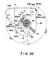
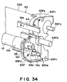
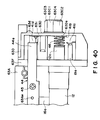
- Figure 21 is a top plan view illustrating a showing of the driving device.
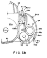
- the black development cartridge Db illustrated in Figure 5 does not have a coating roller.
- the black toner adheres to the development roller 12 due to its own adhesive force, and due to the magnetic force of a magnet (unillustrated) disposed inside the development roller 12.
- the thickness of the layer of the toner, which has adhered to the development roller 12 is regulated by the development blade 16 placed in contact with the peripheral surface of the development roller 12. As the thickness of the toner layer is regulated by the development blade 16, the toner becomes triboelectrically charged.
- the development roller 12 does not contain a magnet. This is because the black toner in this embodiment is a magnetic toner, whereas the magenta, cyan and yellow toners are nonmagnetic toners.
- the apparatus main assembly 13 is provided with a development cartridge opening 17, which is located at a predetermined position in the apparatus main assembly 30, and the width of which is greater than the dimension of the development cartridge D in the longitudinal direction.
- a cover 18 is pivotally attached to expose or cover the opening 17. Normally, the development cartridge opening 17 is covered with the cover 18.
- the operator rotates the development cartridge D about the projections 63c and 63g.
- the shutter 64 is opened, and the development roller 12 is exposed from the cartridge frame 63 in a manner to directly and squarely face the photosensitive drum 1, being readied for image development.
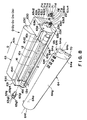
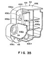
- the cartridge frame 63 of the development cartridge D is provided with an opening 63b, which extends in the longitudinal direction of the cartridge frame 63.
- the development roller 12 is attached to the cartridge frame 63 in such a manner that the development roller 12 is exposed through the opening 63b.
- the cartridge frame 63 is provided with a projection 63c, which is integrally formed with the cartridge frame 63, and projects outward from the approximate center of a longitudinal end wall 63h of the cartridge frame 63.
- the projection 63 acts as a guide when the development cartridge D is inserted into the apparatus main assembly 30, and also acts as a rotational axis when the development cartridge D is installed, or removed from, the apparatus main assembly 30.
- the projection 63c is in the form of a cylinder, and will be described later in more detail.
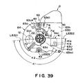
- the anchoring portion 63g1 is provided with a latching portion (unillustrated), which is located at the tip of the anchoring portion 63g1, and the projection 63g is attached to the cartridge frame 63 by engaging this latching portion of the anchoring portion 63gl with the cartridge frame 63.
- the other end of the projection 63g2, that is, the end opposite to the anchoring portion 63gl, of the projection 63g comes in contact with the aforementioned pressing member 26b, which is elastically projecting from the longitudinal end wall 11a of the rotary unit 11.
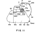
- the locking member 71 is formed of plastic material, and is molded in a single piece.
- the arm portion 71g that is, a portion of the locking member 71, comes in contact with a solid projection of the apparatus main assembly 30.
- the supporting portion 71a is elastically bent, and as a result, the latching portion 71b is disengaged from the latching portion catching recess 64t, that is, the shutter 64 is unlocked.
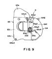
- the semispherical projection 63d which comes in contact with one of the longitudinal ends of the development cartridge D, is provided on only the longitudinal end wall 63h of the cartridge frame 63. Accordingly, the shutter 64 is provided with a hole 64u, in which the projection 63d engages, and which is located so as to align with the projection 63d when the development cartridge D is in the rotary unit 11.
- the projection 63d is in engagement with the hole 64u, and therefore, even if the shutter 64 is released from the locking member 71, the cartridge frame 63 does not unexpectedly rotate.
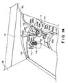
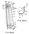
- the projection 63c located at one of the longitudinal ends of the development cartridge D enters the straight portion of the projection guiding portion 59d between the straight ribs 59c as illustrated in Figure 16.
- the projection 63c comprises a cut portion 63c1, the peripheral surface. of which is constituted of two parallel flat surface, and two arcing surfaces located between the flat surfaces.
- the distance (width W1 in Figure 14) between the two straight ribs 59c is such that the projection 63c is allowed to be guided through the projection guiding portion 59d only when the projection 63c is positioned so that the flat surfaces of the cut portion 63c1 become parallel to the straight ribs 59c.
- the developing cartridges D (Dm, Dc, Dy, Db) have the mounting portions which are the same in the configurations, dimensions or the like, and are mountable to any of the cartridge mounting portions of the rotary unit 11.
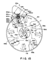
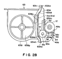
- the rotary unit 11 has a disk-like flanges llf, llg at the opposite ends thereof, and the center of the flange is supported by shaft means 10.
- the cartridge mounting portions 14 are disposed in the rotary unit 11 equidistantly in the circumferential direction. More particularly, four cartridge mounting portions 14 are provided equidistantly, and are to receive developing cartridges Dm, Dc, Dy, Db respectively (cartridge mounting portions 14m, 14c, 14y, 14b).
- the first light-transmissive member is concave toward inside of the toner accommodating portion 63a.
- the developing cartridge D has an urged portion 63U urged by an urging member (e.g. compression coil spring 10b of the urging means 25) provided in the main assembly 30 of the apparatus when the developing cartridge D is mounted to the main assembly 30.
- an urging member e.g. compression coil spring 10b of the urging means 25
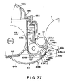
- the toner feeding member 15 and the elastic blade 16c (cleaning portion) are of resin material and are integrally molded.
- the toner feeding member 15 and the elastic blade 16c are provided on the same shaft 15c. Therefore, the toner feeding member 15 and the elastic blade 16 can be rotated through one driving mechanism.
- the first, second light-transmissive members are disposed outside the developing zone in the longitudinal direction of the developing roller, and therefore, the rotation of the cleaning portion does not adversely affect the developing function.
- the toner accommodated in said toner accommodating portion 63a is yellow color toner, magenta color toner or cyan color toner, said developing cartridge further comprising an application roller 19 for depositing the toner on a peripheral surface of said developing roller 12, and the bias received from the main assembly is applied to said developing roller 12, said developing blade 16 and said application roller 19.
- the developer cartridge with the developing bias contact pivots in the rotary unit about the center of rotation of the driving force receiving member (pressure for urging the developing roller to the photosensitive drum).
- the driving force receiving member pressure for urging the developing roller to the photosensitive drum.
Applications Claiming Priority (6)
| Application Number | Priority Date | Filing Date | Title |
|---|---|---|---|
| JP19502797 | 1997-07-03 | ||
| JP19502797 | 1997-07-03 | ||
| JP195027/97 | 1997-07-03 | ||
| JP18614498A JP3728104B2 (ja) | 1997-07-03 | 1998-07-01 | 現像カートリッジサイドカバー及び現像カートリッジ |
| JP18614498 | 1998-07-01 | ||
| JP186144/98 | 1998-07-01 |
Publications (3)
| Publication Number | Publication Date |
|---|---|
| EP0889375A2 true EP0889375A2 (fr) | 1999-01-07 |
| EP0889375A3 EP0889375A3 (fr) | 1999-09-08 |
| EP0889375B1 EP0889375B1 (fr) | 2003-12-17 |
Family
ID=26503569
Family Applications (1)
| Application Number | Title | Priority Date | Filing Date |
|---|---|---|---|
| EP98305329A Expired - Lifetime EP0889375B1 (fr) | 1997-07-03 | 1998-07-03 | Couvercle latéral d'un ensemble de développement, son procédé de montage et ensemble de développement |
Country Status (6)
| Country | Link |
|---|---|
| US (1) | US6256467B1 (fr) |
| EP (1) | EP0889375B1 (fr) |
| JP (1) | JP3728104B2 (fr) |
| CN (1) | CN1099621C (fr) |
| AU (1) | AU723347B2 (fr) |
| DE (1) | DE69820537T2 (fr) |
Cited By (2)
| Publication number | Priority date | Publication date | Assignee | Title |
|---|---|---|---|---|
| EP0984337A2 (fr) * | 1998-08-31 | 2000-03-08 | Canon Kabushiki Kaisha | Méthode de montage et de démontage d'une unité de développement |
| WO2018166586A1 (fr) * | 2017-03-14 | 2018-09-20 | Hp Indigo B.V. | Socle de support d'unité de développement d'encre binaire |
Families Citing this family (21)
| Publication number | Priority date | Publication date | Assignee | Title |
|---|---|---|---|---|
| JP3840063B2 (ja) | 2001-04-27 | 2006-11-01 | キヤノン株式会社 | プロセスカートリッジ |
| JP3542588B2 (ja) * | 2002-09-30 | 2004-07-14 | キヤノン株式会社 | 現像カートリッジ、一端サイドカバーの取付け方法、他端サイドカバーの取付け方法、及び、電子写真画像形成装置 |
| JP3809412B2 (ja) * | 2002-09-30 | 2006-08-16 | キヤノン株式会社 | 現像カートリッジ及び電子写真画像形成装置 |
| US6801734B1 (en) * | 2003-05-16 | 2004-10-05 | Static Control Components, Inc. | Method and apparatus for reassembling a toner cartridge |
| JP4652783B2 (ja) * | 2003-12-10 | 2011-03-16 | キヤノン株式会社 | 現像剤供給容器 |
| US20050153160A1 (en) * | 2004-01-12 | 2005-07-14 | Yourong Liu | Durable thermal barrier coating having low thermal conductivity |
| US7292802B2 (en) * | 2004-07-29 | 2007-11-06 | Brother Kogyo Kabushiki Kaisha | Developing apparatus and assembly method of developing apparatus |
| JP4735946B2 (ja) * | 2005-03-14 | 2011-07-27 | 富士ゼロックス株式会社 | 現像カートリッジ |
| JP4622830B2 (ja) * | 2005-11-30 | 2011-02-02 | ブラザー工業株式会社 | 現像カートリッジ、プロセスユニットおよび画像形成装置 |
| JP4498407B2 (ja) | 2006-12-22 | 2010-07-07 | キヤノン株式会社 | プロセスカートリッジ、電子写真画像形成装置、及び、電子写真感光体ドラムユニット |
| JP4948382B2 (ja) | 2006-12-22 | 2012-06-06 | キヤノン株式会社 | 感光ドラム取り付け用カップリング部材 |
| JP5311854B2 (ja) | 2007-03-23 | 2013-10-09 | キヤノン株式会社 | 電子写真画像形成装置、現像装置、及び、カップリング部材 |
| JP5306050B2 (ja) | 2008-06-20 | 2013-10-02 | キヤノン株式会社 | カートリッジ、カップリング部材の取り付け方法、及び、カップリング部材の取り外し方法 |
| JP5127584B2 (ja) | 2008-06-20 | 2013-01-23 | キヤノン株式会社 | ドラムユニット、及び、電子写真画像形成装置 |
| JP5943716B2 (ja) | 2012-06-04 | 2016-07-05 | キヤノン株式会社 | 現像カートリッジ |
| JP6066639B2 (ja) * | 2012-09-13 | 2017-01-25 | キヤノン株式会社 | 現像装置及びプロセスカートリッジ |
| US9964891B2 (en) * | 2014-12-17 | 2018-05-08 | Lexmark International, Inc. | Systems for optical communication between an image forming device and a replaceable unit of the image forming device |
| US9519254B2 (en) | 2014-12-17 | 2016-12-13 | Lexmark International, Inc. | Systems for configuring settings of an electronic device for customization thereof |
| JP6529282B2 (ja) * | 2015-02-27 | 2019-06-12 | キヤノン株式会社 | サイド部材およびカートリッジ並びに画像形成装置 |
| US10282721B2 (en) | 2015-06-10 | 2019-05-07 | Lexmark International, Inc. | System and method for price verification in a retail environment |
| CN108762030B (zh) * | 2018-05-02 | 2019-07-23 | 中山诚威科技有限公司 | 显影盒以及显影盒的使用方法 |
Citations (8)
| Publication number | Priority date | Publication date | Assignee | Title |
|---|---|---|---|---|
| US4713673A (en) * | 1985-04-08 | 1987-12-15 | Kabushiki Kaisha Toshiba | Image forming apparatus in which multiple developing units are supported and moved relative to an image carrier |
| EP0613060A2 (fr) * | 1993-02-24 | 1994-08-31 | Canon Kabushiki Kaisha | Ensemble de développement comprenant un élément pour supporter de manière rotative un dispositif de développement, et appareil de développement |
| JPH0736248A (ja) * | 1993-07-16 | 1995-02-07 | Canon Inc | 画像形成装置 |
| JPH0756417A (ja) * | 1993-08-09 | 1995-03-03 | Ricoh Co Ltd | 回転型現像装置 |
| US5646721A (en) * | 1994-06-01 | 1997-07-08 | Ricoh Company, Ltd. | Image forming apparatus for supplying power to members of a rotary developing device |
| EP0794471A1 (fr) * | 1996-03-05 | 1997-09-10 | Canon Kabushiki Kaisha | Ensemble de développement |
| EP0889374A2 (fr) * | 1997-07-03 | 1999-01-07 | Canon Kabushiki Kaisha | Unité de developpement et appareil electrophotographique de formation d'images |
| EP0889378A2 (fr) * | 1997-07-03 | 1999-01-07 | Canon Kabushiki Kaisha | Unité de developpement et appareil electrophotographique de formation d'images |
Family Cites Families (3)
| Publication number | Priority date | Publication date | Assignee | Title |
|---|---|---|---|---|
| JP3298728B2 (ja) * | 1993-11-12 | 2002-07-08 | 株式会社リコー | 画像形成装置 |
| US5648838A (en) * | 1994-11-01 | 1997-07-15 | Steven Bruce Michlin | Method and apparatus for electrically connecting a developer roller to a bias source |
| JPH08292704A (ja) * | 1995-04-21 | 1996-11-05 | Canon Inc | プロセスカートリッジ及び電子写真画像形成装置 |
-
1998
- 1998-07-01 JP JP18614498A patent/JP3728104B2/ja not_active Expired - Lifetime
- 1998-07-02 US US09/109,716 patent/US6256467B1/en not_active Expired - Lifetime
- 1998-07-02 AU AU74057/98A patent/AU723347B2/en not_active Ceased
- 1998-07-03 DE DE69820537T patent/DE69820537T2/de not_active Expired - Lifetime
- 1998-07-03 CN CN98117412A patent/CN1099621C/zh not_active Expired - Fee Related
- 1998-07-03 EP EP98305329A patent/EP0889375B1/fr not_active Expired - Lifetime
Patent Citations (8)
| Publication number | Priority date | Publication date | Assignee | Title |
|---|---|---|---|---|
| US4713673A (en) * | 1985-04-08 | 1987-12-15 | Kabushiki Kaisha Toshiba | Image forming apparatus in which multiple developing units are supported and moved relative to an image carrier |
| EP0613060A2 (fr) * | 1993-02-24 | 1994-08-31 | Canon Kabushiki Kaisha | Ensemble de développement comprenant un élément pour supporter de manière rotative un dispositif de développement, et appareil de développement |
| JPH0736248A (ja) * | 1993-07-16 | 1995-02-07 | Canon Inc | 画像形成装置 |
| JPH0756417A (ja) * | 1993-08-09 | 1995-03-03 | Ricoh Co Ltd | 回転型現像装置 |
| US5646721A (en) * | 1994-06-01 | 1997-07-08 | Ricoh Company, Ltd. | Image forming apparatus for supplying power to members of a rotary developing device |
| EP0794471A1 (fr) * | 1996-03-05 | 1997-09-10 | Canon Kabushiki Kaisha | Ensemble de développement |
| EP0889374A2 (fr) * | 1997-07-03 | 1999-01-07 | Canon Kabushiki Kaisha | Unité de developpement et appareil electrophotographique de formation d'images |
| EP0889378A2 (fr) * | 1997-07-03 | 1999-01-07 | Canon Kabushiki Kaisha | Unité de developpement et appareil electrophotographique de formation d'images |
Non-Patent Citations (2)
| Title |
|---|
| PATENT ABSTRACTS OF JAPAN vol. 095, no. 005, 30 June 1995 (1995-06-30) & JP 07 036248 A (CANON INC), 7 February 1995 (1995-02-07) * |
| PATENT ABSTRACTS OF JAPAN vol. 095, no. 006, 31 July 1995 (1995-07-31) & JP 07 056417 A (RICOH CO LTD), 3 March 1995 (1995-03-03) * |
Cited By (5)
| Publication number | Priority date | Publication date | Assignee | Title |
|---|---|---|---|---|
| EP0984337A2 (fr) * | 1998-08-31 | 2000-03-08 | Canon Kabushiki Kaisha | Méthode de montage et de démontage d'une unité de développement |
| EP0984337A3 (fr) * | 1998-08-31 | 2000-12-13 | Canon Kabushiki Kaisha | Méthode de montage et de démontage d'une unité de développement |
| US6381430B1 (en) | 1998-08-31 | 2002-04-30 | Canon Kabushiki Kaisha | Assembling and disassembling methods for developing cartridge |
| WO2018166586A1 (fr) * | 2017-03-14 | 2018-09-20 | Hp Indigo B.V. | Socle de support d'unité de développement d'encre binaire |
| US10877426B2 (en) | 2017-03-14 | 2020-12-29 | Hp Indigo B.V. | Binary ink development unit support stand |
Also Published As
| Publication number | Publication date |
|---|---|
| AU723347B2 (en) | 2000-08-24 |
| EP0889375A3 (fr) | 1999-09-08 |
| DE69820537D1 (de) | 2004-01-29 |
| EP0889375B1 (fr) | 2003-12-17 |
| JP3728104B2 (ja) | 2005-12-21 |
| US6256467B1 (en) | 2001-07-03 |
| AU7405798A (en) | 1999-01-14 |
| CN1099621C (zh) | 2003-01-22 |
| JPH1173009A (ja) | 1999-03-16 |
| CN1205460A (zh) | 1999-01-20 |
| DE69820537T2 (de) | 2004-09-30 |
Similar Documents
| Publication | Publication Date | Title |
|---|---|---|
| US6029027A (en) | Developing cartridge and electrophotographic image forming apparatus | |
| US6032002A (en) | Shutter, developing cartridge and electrophotographic image forming apparatus | |
| EP0889375B1 (fr) | Couvercle latéral d'un ensemble de développement, son procédé de montage et ensemble de développement | |
| US6002898A (en) | Developing cartridge and image forming apparatus | |
| EP0889378B1 (fr) | Unité de developpement et appareil electrophotographique de formation d'images | |
| EP0984337A2 (fr) | Méthode de montage et de démontage d'une unité de développement | |
| JP3869902B2 (ja) | 現像カートリッジ及び電子写真画像形成装置 | |
| US6345164B1 (en) | Shutter pin and developing cartridge | |
| JP3869903B2 (ja) | 電子写真画像形成装置 | |
| US5940657A (en) | Developing cartridge | |
| US6104895A (en) | Developing cartridge side cover, mounting method thereof and developing cartridge | |
| JPH11282250A (ja) | 現像装置及びプロセスカートリッジ | |
| US6314255B1 (en) | Developing frame for connection with a toner frame wherein a toner application roller crosses a connecting surface of the frames | |
| JP2000131950A (ja) | 現像カートリッジの組み立て方法、及び、現像ブレードの交換方法 | |
| JP2000075609A (ja) | 現像カートリッジ及び電子写真画像形成装置、及び、サイドカバー | |
| JP2000131938A (ja) | 現像装置及び電子写真画像形成装置 |
Legal Events
| Date | Code | Title | Description |
|---|---|---|---|
| PUAI | Public reference made under article 153(3) epc to a published international application that has entered the european phase |
Free format text: ORIGINAL CODE: 0009012 |
|
| AK | Designated contracting states |
Kind code of ref document: A2 Designated state(s): CH DE FR GB IT LI |
|
| AX | Request for extension of the european patent |
Free format text: AL;LT;LV;MK;RO;SI |
|
| PUAL | Search report despatched |
Free format text: ORIGINAL CODE: 0009013 |
|
| AK | Designated contracting states |
Kind code of ref document: A3 Designated state(s): AT BE CH CY DE DK ES FI FR GB GR IE IT LI LU MC NL PT SE |
|
| AX | Request for extension of the european patent |
Free format text: AL;LT;LV;MK;RO;SI |
|
| 17P | Request for examination filed |
Effective date: 20000121 |
|
| AKX | Designation fees paid |
Free format text: CH DE FR GB IT LI |
|
| 17Q | First examination report despatched |
Effective date: 20020220 |
|
| GRAH | Despatch of communication of intention to grant a patent |
Free format text: ORIGINAL CODE: EPIDOS IGRA |
|
| GRAS | Grant fee paid |
Free format text: ORIGINAL CODE: EPIDOSNIGR3 |
|
| GRAA | (expected) grant |
Free format text: ORIGINAL CODE: 0009210 |
|
| AK | Designated contracting states |
Kind code of ref document: B1 Designated state(s): CH DE FR GB IT LI |
|
| REG | Reference to a national code |
Ref country code: GB Ref legal event code: FG4D |
|
| REG | Reference to a national code |
Ref country code: CH Ref legal event code: EP |
|
| REF | Corresponds to: |
Ref document number: 69820537 Country of ref document: DE Date of ref document: 20040129 Kind code of ref document: P |
|
| REG | Reference to a national code |
Ref country code: CH Ref legal event code: NV Representative=s name: BOVARD AG PATENTANWAELTE |
|
| ET | Fr: translation filed | ||
| PLBE | No opposition filed within time limit |
Free format text: ORIGINAL CODE: 0009261 |
|
| STAA | Information on the status of an ep patent application or granted ep patent |
Free format text: STATUS: NO OPPOSITION FILED WITHIN TIME LIMIT |
|
| 26N | No opposition filed |
Effective date: 20040920 |
|
| REG | Reference to a national code |
Ref country code: CH Ref legal event code: PFA Owner name: CANON KABUSHIKI KAISHA Free format text: CANON KABUSHIKI KAISHA#30-2, 3-CHOME, SHIMOMARUKO, OHTA-KU#TOKYO (JP) -TRANSFER TO- CANON KABUSHIKI KAISHA#30-2, 3-CHOME, SHIMOMARUKO, OHTA-KU#TOKYO (JP) |
|
| PGFP | Annual fee paid to national office [announced via postgrant information from national office to epo] |
Ref country code: CH Payment date: 20110718 Year of fee payment: 14 |
|
| PGFP | Annual fee paid to national office [announced via postgrant information from national office to epo] |
Ref country code: GB Payment date: 20120730 Year of fee payment: 15 |
|
| PGFP | Annual fee paid to national office [announced via postgrant information from national office to epo] |
Ref country code: IT Payment date: 20120711 Year of fee payment: 15 Ref country code: FR Payment date: 20120808 Year of fee payment: 15 Ref country code: DE Payment date: 20120731 Year of fee payment: 15 |
|
| REG | Reference to a national code |
Ref country code: CH Ref legal event code: PL |
|
| GBPC | Gb: european patent ceased through non-payment of renewal fee |
Effective date: 20130703 |
|
| REG | Reference to a national code |
Ref country code: FR Ref legal event code: ST Effective date: 20140331 |
|
| PG25 | Lapsed in a contracting state [announced via postgrant information from national office to epo] |
Ref country code: CH Free format text: LAPSE BECAUSE OF NON-PAYMENT OF DUE FEES Effective date: 20130731 Ref country code: DE Free format text: LAPSE BECAUSE OF NON-PAYMENT OF DUE FEES Effective date: 20140201 Ref country code: LI Free format text: LAPSE BECAUSE OF NON-PAYMENT OF DUE FEES Effective date: 20130731 Ref country code: GB Free format text: LAPSE BECAUSE OF NON-PAYMENT OF DUE FEES Effective date: 20130703 |
|
| REG | Reference to a national code |
Ref country code: DE Ref legal event code: R119 Ref document number: 69820537 Country of ref document: DE Effective date: 20140201 |
|
| PG25 | Lapsed in a contracting state [announced via postgrant information from national office to epo] |
Ref country code: IT Free format text: LAPSE BECAUSE OF NON-PAYMENT OF DUE FEES Effective date: 20130703 Ref country code: FR Free format text: LAPSE BECAUSE OF NON-PAYMENT OF DUE FEES Effective date: 20130731 |