EP0889179B1 - Bridge of shock-absorbing construction - Google Patents
Bridge of shock-absorbing construction Download PDFInfo
- Publication number
- EP0889179B1 EP0889179B1 EP98111604A EP98111604A EP0889179B1 EP 0889179 B1 EP0889179 B1 EP 0889179B1 EP 98111604 A EP98111604 A EP 98111604A EP 98111604 A EP98111604 A EP 98111604A EP 0889179 B1 EP0889179 B1 EP 0889179B1
- Authority
- EP
- European Patent Office
- Prior art keywords
- shock
- shock absorbers
- bridge according
- horizontal members
- bridge
- Prior art date
- Legal status (The legal status is an assumption and is not a legal conclusion. Google has not performed a legal analysis and makes no representation as to the accuracy of the status listed.)
- Expired - Lifetime
Links
- 238000010276 construction Methods 0.000 title claims abstract description 35
- 230000035939 shock Effects 0.000 claims abstract description 260
- 239000006096 absorbing agent Substances 0.000 claims abstract description 190
- 239000000463 material Substances 0.000 claims abstract description 29
- 238000010521 absorption reaction Methods 0.000 claims description 29
- 230000006835 compression Effects 0.000 claims description 24
- 238000007906 compression Methods 0.000 claims description 24
- 229920005989 resin Polymers 0.000 claims description 23
- 239000011347 resin Substances 0.000 claims description 23
- 229910052751 metal Inorganic materials 0.000 claims description 10
- 239000002184 metal Substances 0.000 claims description 10
- 239000002250 absorbent Substances 0.000 claims 1
- 230000002745 absorbent Effects 0.000 claims 1
- 238000006243 chemical reaction Methods 0.000 description 34
- 210000004027 cell Anatomy 0.000 description 15
- 229920001971 elastomer Polymers 0.000 description 14
- 230000000149 penetrating effect Effects 0.000 description 13
- 210000002421 cell wall Anatomy 0.000 description 9
- 238000011056 performance test Methods 0.000 description 9
- 230000000704 physical effect Effects 0.000 description 9
- 239000005060 rubber Substances 0.000 description 8
- 230000000052 comparative effect Effects 0.000 description 7
- 238000001746 injection moulding Methods 0.000 description 7
- 238000000034 method Methods 0.000 description 7
- 238000012669 compression test Methods 0.000 description 6
- 239000000806 elastomer Substances 0.000 description 6
- XLYOFNOQVPJJNP-UHFFFAOYSA-N water Substances O XLYOFNOQVPJJNP-UHFFFAOYSA-N 0.000 description 6
- 238000006073 displacement reaction Methods 0.000 description 5
- JEIPFZHSYJVQDO-UHFFFAOYSA-N iron(III) oxide Inorganic materials O=[Fe]O[Fe]=O JEIPFZHSYJVQDO-UHFFFAOYSA-N 0.000 description 5
- 238000012423 maintenance Methods 0.000 description 5
- 230000002265 prevention Effects 0.000 description 5
- 230000015572 biosynthetic process Effects 0.000 description 4
- 230000000694 effects Effects 0.000 description 4
- 230000005489 elastic deformation Effects 0.000 description 4
- 206010016173 Fall Diseases 0.000 description 3
- 229910052782 aluminium Inorganic materials 0.000 description 3
- XAGFODPZIPBFFR-UHFFFAOYSA-N aluminium Chemical compound [Al] XAGFODPZIPBFFR-UHFFFAOYSA-N 0.000 description 3
- 229920001084 poly(chloroprene) Polymers 0.000 description 3
- 229920000728 polyester Polymers 0.000 description 3
- 239000010935 stainless steel Substances 0.000 description 3
- 229910001220 stainless steel Inorganic materials 0.000 description 3
- 229920005992 thermoplastic resin Polymers 0.000 description 3
- 229920001187 thermosetting polymer Polymers 0.000 description 3
- 229910001369 Brass Inorganic materials 0.000 description 2
- 229920000049 Carbon (fiber) Polymers 0.000 description 2
- RYGMFSIKBFXOCR-UHFFFAOYSA-N Copper Chemical compound [Cu] RYGMFSIKBFXOCR-UHFFFAOYSA-N 0.000 description 2
- 229910000737 Duralumin Inorganic materials 0.000 description 2
- XEEYBQQBJWHFJM-UHFFFAOYSA-N Iron Chemical compound [Fe] XEEYBQQBJWHFJM-UHFFFAOYSA-N 0.000 description 2
- PXHVJJICTQNCMI-UHFFFAOYSA-N Nickel Chemical compound [Ni] PXHVJJICTQNCMI-UHFFFAOYSA-N 0.000 description 2
- 239000004677 Nylon Substances 0.000 description 2
- 229910000831 Steel Inorganic materials 0.000 description 2
- 230000002238 attenuated effect Effects 0.000 description 2
- 239000011324 bead Substances 0.000 description 2
- 239000010951 brass Substances 0.000 description 2
- 239000006229 carbon black Substances 0.000 description 2
- 239000004917 carbon fiber Substances 0.000 description 2
- 229910052802 copper Inorganic materials 0.000 description 2
- 239000010949 copper Substances 0.000 description 2
- 238000011161 development Methods 0.000 description 2
- 238000002474 experimental method Methods 0.000 description 2
- 238000001125 extrusion Methods 0.000 description 2
- 239000000835 fiber Substances 0.000 description 2
- 239000000945 filler Substances 0.000 description 2
- 239000011521 glass Substances 0.000 description 2
- 239000003365 glass fiber Substances 0.000 description 2
- 150000002739 metals Chemical class 0.000 description 2
- 238000000465 moulding Methods 0.000 description 2
- 229920001778 nylon Polymers 0.000 description 2
- 230000001681 protective effect Effects 0.000 description 2
- 230000009467 reduction Effects 0.000 description 2
- 239000012779 reinforcing material Substances 0.000 description 2
- 230000002441 reversible effect Effects 0.000 description 2
- 238000000926 separation method Methods 0.000 description 2
- 239000007787 solid Substances 0.000 description 2
- 239000010959 steel Substances 0.000 description 2
- 239000000454 talc Substances 0.000 description 2
- 229910052623 talc Inorganic materials 0.000 description 2
- 238000012360 testing method Methods 0.000 description 2
- 229920006346 thermoplastic polyester elastomer Polymers 0.000 description 2
- QNRATNLHPGXHMA-XZHTYLCXSA-N (r)-(6-ethoxyquinolin-4-yl)-[(2s,4s,5r)-5-ethyl-1-azabicyclo[2.2.2]octan-2-yl]methanol;hydrochloride Chemical compound Cl.C([C@H]([C@H](C1)CC)C2)CN1[C@@H]2[C@H](O)C1=CC=NC2=CC=C(OCC)C=C21 QNRATNLHPGXHMA-XZHTYLCXSA-N 0.000 description 1
- 229910000838 Al alloy Inorganic materials 0.000 description 1
- 239000004952 Polyamide Substances 0.000 description 1
- ATJFFYVFTNAWJD-UHFFFAOYSA-N Tin Chemical compound [Sn] ATJFFYVFTNAWJD-UHFFFAOYSA-N 0.000 description 1
- RTAQQCXQSZGOHL-UHFFFAOYSA-N Titanium Chemical compound [Ti] RTAQQCXQSZGOHL-UHFFFAOYSA-N 0.000 description 1
- HCHKCACWOHOZIP-UHFFFAOYSA-N Zinc Chemical compound [Zn] HCHKCACWOHOZIP-UHFFFAOYSA-N 0.000 description 1
- 239000000654 additive Substances 0.000 description 1
- 239000003963 antioxidant agent Substances 0.000 description 1
- 239000002216 antistatic agent Substances 0.000 description 1
- 230000003139 buffering effect Effects 0.000 description 1
- 238000005266 casting Methods 0.000 description 1
- 239000003795 chemical substances by application Substances 0.000 description 1
- 238000000748 compression moulding Methods 0.000 description 1
- 230000008602 contraction Effects 0.000 description 1
- 238000005520 cutting process Methods 0.000 description 1
- 230000006866 deterioration Effects 0.000 description 1
- 238000005553 drilling Methods 0.000 description 1
- 239000000975 dye Substances 0.000 description 1
- -1 flame retarders Substances 0.000 description 1
- 239000004088 foaming agent Substances 0.000 description 1
- 239000012760 heat stabilizer Substances 0.000 description 1
- 230000006872 improvement Effects 0.000 description 1
- 238000003780 insertion Methods 0.000 description 1
- 230000037431 insertion Effects 0.000 description 1
- 238000007689 inspection Methods 0.000 description 1
- 229910052742 iron Inorganic materials 0.000 description 1
- 239000011133 lead Substances 0.000 description 1
- 238000004519 manufacturing process Methods 0.000 description 1
- 230000007246 mechanism Effects 0.000 description 1
- 239000000203 mixture Substances 0.000 description 1
- 238000012986 modification Methods 0.000 description 1
- 230000004048 modification Effects 0.000 description 1
- 229910052759 nickel Inorganic materials 0.000 description 1
- 239000000049 pigment Substances 0.000 description 1
- 239000004033 plastic Substances 0.000 description 1
- 229920003023 plastic Polymers 0.000 description 1
- 239000004014 plasticizer Substances 0.000 description 1
- 229920002647 polyamide Polymers 0.000 description 1
- 229920006124 polyolefin elastomer Polymers 0.000 description 1
- 229920003225 polyurethane elastomer Polymers 0.000 description 1
- 229920005749 polyurethane resin Polymers 0.000 description 1
- 230000003405 preventing effect Effects 0.000 description 1
- 238000012545 processing Methods 0.000 description 1
- 230000002829 reductive effect Effects 0.000 description 1
- 230000003014 reinforcing effect Effects 0.000 description 1
- 230000008439 repair process Effects 0.000 description 1
- 150000003839 salts Chemical class 0.000 description 1
- 238000004088 simulation Methods 0.000 description 1
- 239000003381 stabilizer Substances 0.000 description 1
- 230000003068 static effect Effects 0.000 description 1
- 229920002397 thermoplastic olefin Polymers 0.000 description 1
- 229910052718 tin Inorganic materials 0.000 description 1
- 239000011135 tin Substances 0.000 description 1
- 239000010936 titanium Substances 0.000 description 1
- 229910052719 titanium Inorganic materials 0.000 description 1
- 229940124543 ultraviolet light absorber Drugs 0.000 description 1
- 239000011345 viscous material Substances 0.000 description 1
- 238000005303 weighing Methods 0.000 description 1
- 229910052725 zinc Inorganic materials 0.000 description 1
- 239000011701 zinc Substances 0.000 description 1
Images


Classifications
-
- E—FIXED CONSTRUCTIONS
- E04—BUILDING
- E04H—BUILDINGS OR LIKE STRUCTURES FOR PARTICULAR PURPOSES; SWIMMING OR SPLASH BATHS OR POOLS; MASTS; FENCING; TENTS OR CANOPIES, IN GENERAL
- E04H9/00—Buildings, groups of buildings or shelters adapted to withstand or provide protection against abnormal external influences, e.g. war-like action, earthquake or extreme climate
- E04H9/02—Buildings, groups of buildings or shelters adapted to withstand or provide protection against abnormal external influences, e.g. war-like action, earthquake or extreme climate withstanding earthquake or sinking of ground
- E04H9/021—Bearing, supporting or connecting constructions specially adapted for such buildings
-
- E—FIXED CONSTRUCTIONS
- E01—CONSTRUCTION OF ROADS, RAILWAYS, OR BRIDGES
- E01D—CONSTRUCTION OF BRIDGES, ELEVATED ROADWAYS OR VIADUCTS; ASSEMBLY OF BRIDGES
- E01D19/00—Structural or constructional details of bridges
- E01D19/04—Bearings; Hinges
Definitions
- the present invention relates to a bridge of novel shock-absorbing construction. More particularly, it relates to a bridge of shock-absorbing construction in which shock absorbers are disposed at the points of contact between the horizontal members or between the horizontal member and the vertical member and on the connectors for connecting the adjacent horizontal members or for connecting the horizontal member and the vertical member to ensure the effective absorption or attenuation of a shock.
- a bridge of such construction can effectively absorb or attenuate the shock of collisions between the horizontal members or between the horizontal member and the vertical member to prevent these members from being damaged and further to prevent the horizontal member from falling from the vertical member.
- a slippage-preventive protrusion i.e., bracket
- a bridge falling-preventive wall i.e., safety wall
- the shock absorber which has been used in the bridge of such shock-absorbing construction may include molded rubber parts characterized by good restitution.
- molded rubber parts characterized by good restitution.
- the use of molded rubber parts gives a limitation on the size of shock absorbers, leading to a deterioration in the shock-absorbing performance, which makes it difficult to obtain satisfactory effects on the prevention of breakage or falling of bridges against strong and shock vibration.
- the shock absorption may also be increased by the use of molded rubber parts made thicker or by the combined use of more than one molded rubber part, in which either case, however, the shock absorbers become large-sized, so that they are difficult to dispose at very limited sites, in addition to a steep rise in material costs and an increase in weight.
- shock absorbers other than molded rubber parts have also been known, for example, metal springs, shock-attenuating friction members, and shock-attenuating hydraulic members.
- Metal springs although they have excellent shock-absorbing performance, have an inevitable problem of rust formation; therefore, elaborate maintenance is needed after construction and, from a viewpoint of resistance to rust and weather, they are not suitable for use in the bridges to be constructed at locations exposed to salt water, such as coastal bridges and marine connecting bridges.
- friction or hydraulic shock-attenuating members are structurally complicated and both much expensive and heavy, and they cannot keep their original performance without undergoing proper maintenance.
- Japanese Patent Publication No. 61-12779/1986 discloses a technique for the improvement of shock-absorbing performance where hollow molded parts of a thermoplastic resin elastomer are provided with permanent strain by pre-compression in the axial direction.
- molded resin parts although they have improved ability to function as an elastic body, have poor performance of absorbing the energy of compression, so that they cannot be expected to have satisfactory shock-absorbing performance for use in the prevention of bridge falling caused by earthquakes or other factors.
- CA-A-1206981 discloses a deflection control device in which viscoelastic discs are first compressed to damp relative movement and thereafter during excessive movement the viscous material is extruded through perforations to absorb energy. In such a structure there is no intentional buckling or permanent deformation of the wall elements.
- GB-A-1084064 discloses a foundation arrangement for protecting buildings in which the foundation arrangement bears the load of the building in the vertical direction.
- GB-A-2305487 disclosed an impact energy absorber having a low initial load which is constructed from stainless steel honeycomb sections and is formed into a cuboid shape with axes of the honeycomb cells parallel to one axis of the cuboid.
- EP-A-0705994 discloses an impact energy absorptive structure which is made of plastic materials suitable for moulding processing, and is designed to suit different degrees of impact loading.
- the present inventors have developed a shock absorber formed from an elastic resin, comprising more than one arch-, dome-, or honeycomb-shaped member capable of causing deformation by compression, which are disposed on a perforated or non-perforated flat plate of an elastic resin, and thereby having cushioning properties; and they have proceeded with various studies to put such a shock absorber to practical use.
- This type of shock absorbers is suitable for some applications in which they are widely spread over the side wall of a road or the floor of a building to exhibit uniform cushioning performance over a wide area; however, they are difficult to adopt some applications in which they have to be disposed at limited sites such as points of connection between the adjacent horizontal members or between the horizontal member and the vertical member, and they cannot exhibit satisfactory shock-absorbing performance.
- shock absorbers in the bridge construction are often disposed in the vicinity of horizontal member-bearing portions on the vertical members; therefore, they should not become an obstacle to the maintenance works of the bearing portions, such as inspection, conservation, and repair. Therefore, they are required to be small-sized and lightweight, and have excellent shock-absorbing performance, i.e., higher absorption of energy of compression rather than reaction; however, the conventional shock absorbers as described above cannot meet these requirements.
- a shock absorber for use in bridges which is small-sized and lightweight, has a simple construction, and exhibits higher absorption of energy of compression rather than reaction, and wherein if it is formed from a material with excellent rust resistance, water resistance, and weatherability, the bridge containing such shock absorbers can find various practical applications, including inland bridges, coastal bridges, and marine connecting bridges, even in which case the bridge is free of maintenance to retain excellent shock-absorbing performance for a long period of time.
- the present invention provides a bridge of shock-absorbing construction, comprising horizontal members arranged in series, vertical members supporting the horizontal members, and connectors for connecting the adjacent horizontal members or for connecting the horizontal member and the vertical member, wherein shock absorbers formed from a material with an elastic modulus in flexure over 1.96133 x 10 7 Pa (200 kgf/cm 2 ) and each having a wall structure in a shock-loading direction are disposed on the connectors or at the points of contact between the horizontal members or between the horizontal member and the vertical member.
- the shock absorber preferably causes buckling deformation or permanent deformation in the wall structure by compression when loaded with the shock.
- the bridge of shock-absorbing construction contains horizontal members arranged in series, vertical members supporting the horizontal members and each optionally having a safety wall, and connectors for connecting the adjacent horizontal members or for connecting the horizontal member and the vertical member, wherein shock absorbers are disposed on the connectors and at the points of contact between the horizontal members or between the horizontal member and the vertical member.
- shock absorbers in a bridge makes it possible to attain effective absorption or attenuation of a shock loaded on the points of contact between the constitutive members of the bridge, for example, by an earthquake, so that the protective portions of the bridge or the neighboring structures can be prevented from being damaged or broken by the shock, and accidental fallings of the horizontal members from the vertical members, i.e., bridge falling accidents, can be prevented from happening.
- the shock absorber has to be formed from a material with an elastic modulus in flexure over 1.96133 x 10 7 Pa (200 kgf/cm 2 ), preferably 4.903325 x 10 7 Pa (500 kgf/cm 2 ), and has a wall structure in a shock-loading direction.
- the term "wall structure in a shock-loading direction" as used herein refers to a wall structure provided substantially parallel to a shock-loading direction. If a shock absorber is formed from a material with an elastic modulus in flexure lower than 1.96133 x 10 7 Pa (200 kgf/cm 2 ), it has insufficient stiffness, so that it causes immediate elastic deformation when loaded with a shock.
- the shock absorber exhibits a decrease in the absorption of shock energy, so that it cannot sufficiently absorb the shock, making it impossible to obtain satisfactory cushioning effects.
- a thicker wall structure in the shock-loading direction is needed for the shock absorber.
- a shock absorber should be made larger in size, which is not preferred with a departure from the purpose of the present invention.
- a shock absorber causes buckling deformation or permanent deformation in the wall structure by compression when loaded with a shock, thereby attaining effective shock absorption. Therefore, a shock absorber is not preferred to have such a structure that absorbs a shock only by its elastic deformation. This is because when sudden large shocks, such as earthquakes, are loaded on the shock absorber with such a structure several times or some dozens of times for a short period of time, the shock absorber cannot have sufficient energy-absorbing performance or may sometimes cause a resonance phenomenon and rather increase the vibration of the horizontal members of a bridge, thereby quickening the breakage of the bridge structure.
- shock absorbers used in the bridge of shock-absorbing construction according to the present invention are roughly divided into the following two types.
- the shock absorber of the first type is mainly disposed at the point of contact between the horizontal members or between the horizontal member and the vertical member.
- the shock absorber of the first type may be disposed either on the safety wall or on the inner side wall of the horizontal member so that the inner side wall of the horizontal member is not brought into direct contact with the safety wall.
- the other is a shock absorber of relatively small size, which is mainly disposed on the connector for connecting the adjacent horizontal members or for connecting the horizontal member and the vertical member (hereinafter referred to as the shock absorber of the second type).
- the shock absorber of the first type is characterized in that it has a multiple wall structure in a shock-loading direction.
- the shock absorber of the first type preferably has a cell structure in which a plurality of cells are joined together through at least a part of each cell wall along the shockloading direction and isolated from each other in the shock-loading direction.
- the cells in the cell structure may be composed of penetrating holes open at both ends, concave cavities open only at one end, or hollow cavities closed at both ends.
- the wall structure in the shock-loading direction which is composed of cell walls in the cell structure, causes buckling deformation to take an accordion shape, thereby attaining effective shock absorption.
- the shock absorber of the first type can preferably absorb compression energy of 4.903325 x 10 5 J/m 3 (50 tf.m/m 3 ) or higher when compressed by these shocks in the shock-loading direction.
- This performance is achieved bv the use of a resin with an elastic modulus in flexure ranging from 4.903325 x 10 7 to 2.6477955 x 10 10 Pa (500 to 270,000 kgf/cm 2 ), preferably 4.903325 x 10 7 to 1.96133 x 10 9 Pa (500 to 20,000 kgf/cm 2 ), or more preferably 7.84532 x 10 7 to 3.92266 x 10 8 Pa (800 to 4000 kgf/cm 2 ), or by the use of a material with an elastic modulus in flexure over 4.903325 x 10 8 Pa (5000 kgf/cm 2 ).
- the shock absorber of the first type may be formed from any natural or synthetic elastic resin, so long as the resin meets the above condition on the elastic modulus in flexure.
- the resin preferably used are thermoplastic polyester elastomers, polyolefin elastomers, polyurethane elastomers, and polyamide elastomers, including their blends in any ratio, and thermosetting resins such as polyurethane resins for use in the casting.
- Particularly preferred are thermoplastic polyester elastomers and polyolefin elastomers because of their excellent weatherability and water resistance.
- the shock absorber of the first type may also be formed from any material, so long as the material meets the above condition on the elastic modulus in flexure.
- a material with excellent rust preventing properties and water resistance is preferred.
- Specific examples of such a material are thermoplastic resins and thermosetting resins; thermoplastic resins and thermosetting resins, each reinforced with fillers (e.g., carbon black, talc, glass beads), fibrous reinforcing materials (e.g., metal fibers, glass fibers, carbon fibers), or whiskers; and metals such as iron, aluminum, nickel, copper, titanium, zinc, tin, lead, aluminum alloys (e.g., duralumin), brass, and stainless steel. Particularly preferred metals are aluminum, copper, brass, duralumin, and stainless steel because of their excellent weatherability and water resistance.
- the shock absorber of the first type which is formed from such a resin or material
- the rise of reaction at a time when the cells serving as escape spaces become smaller with the development of buckling deformation may sometimes become too steep.
- the cells may be filled with other cushioning materials such as foamable resins or rubber.
- the shock absorber of the first type can have further improved initial shock-absorbing performance by the adoption of a wall structure containing such a particular portion in the shock-loading direction that causes first deformation when loaded with a shock.
- the wall structure in the shock-loading direction may preferably be provided with a cutout portion, a stepped portion, or a thin-walled portion.
- the cell structure of the shock absorber preferably has a hexagonal or lower polygonal pattern in a section perpendicular to the shock-loading direction. More preferably, it is a honeycomb structure with a hexagonal pattern.
- the shock absorber of the second type may have a plateau strength of 400 tf/m 2 or higher and absorbs compression energy of 1.96133 x 10 6 J/m 3 (200 tfm/m 3 ) or higher, and the shock absorber of the second type has a cylindrical wall structure in the shock-absorbing direction.
- the shock absorber of the second type is preferably formed from a resin with an elastic modulus in flexure ranging from 1.96133 x 10 7 to 4.903325 x 10 8 Pa (200 to 5000 kgf/cm 2 ), or a material with an elastic modulus in flexure over 4.903325 x 10 8 Pa (5000 kgf/cm 2 ).
- the shock absorber of the second type may preferably have at least one flange.
- the shock absorber of the second type may preferably have a cylindrical wall structure containing such a particular portion in the shock-loading direction that causes first deformation when loaded with a shock.
- the cylindrical wall structure in the shock-loading direction may preferably be provided with a cutout portion or a thin-walled portion, or have an accordion structure.
- the shock absorber of the second type is mainly disposed at the end of a connector for connecting the adjacent horizontal members or for connecting the horizontal member and the vertical member.
- the connector preferably runs through the shock absorber of the second type.
- the connector is preferably a connection cable, i.e., cable-type connector.
- shock absorber of the first type which can be used in the bridge of shock-absorbing construction according to the present invention, and the mechanism of shock absorption will be explained in detail.
- FIG. 1 is a perspective view showing a typical example of the shock absorber of the first type, i.e., a shock absorber with a honeycomb structure, which has been integrally formed from an elastic resin meeting the above condition on the elastic modulus in flexure.
- shock absorber 1 has a cell structure that is composed of many penetrating holes 2, 2, ..., at equal intervals, each having a hexagonal section and each running in the shock-loading direction shown by the thick arrow.
- cell walls 3, 3, ..., separating penetrating holes 2, 2, ... cause elastic deformation and further buckling deformation in the direction of penetrating holes, thereby attaining the effective absorption of the shock.
- the shock absorber of the first type as shown in Figure 1 can absorb a shock by the inherent elasticity of cell walls 3, 3, ..., formed from an elastic resin, and by buckling deformation with penetrating holes 2, 2, ..., serving as escape spaces.
- a suitable stiffness is given to the shock absorber, particularly by cell walls 3, 3, ..., extending in a honeycomb or lattice pattern when viewed in the shock-loading direction, with many penetrating holes 2, 2, ..., running in the shock-loading direction as shown in Figure 1.
- the shock absorber can have both shock-absorbing effects by the above elastic deformation and suitable stiffness, on the whole, so that the shocks of strong vibrations caused by earthquakes or other factors can effectively be absorbed or attenuated.
- the shock absorber of the first type can be provided with a plurality of steps D at the ends, in the holes-running direction, of cell walls 3, 3, ..., separating penetrating holes 2, 2, ..., and the adjustment of height H and number of steps D, depending upon the degree of a possible shock, can improve the initial shock-absorbing performance and can further reduce the reaction to the shock.
- the satisfactory shock-absorbing performance as a shock absorber can preferably be attained by the absorption of compression energy adjusted to 4.903325 x 10 5 J/m 3 (50 tf.m/m 3 ) or higher, more preferably 9.80665 x 10 5 J/m 3 (100 tf.m/m 3 ) or higher, as determined by a load (reaction) vs. compressibility curve, which is obtained for example, when the shock absorber of the first type as shown in Figure 1 is compressed in the holes-running direction (i.e., in the direction of the thick arrow shown in this figure).
- load (reaction) vs. compressibility curve refers to a curve showing the correlation between load (reaction) observed in the compression of a shock absorber and compressibility.
- load (reaction) vs. compressibility curve steeply rises in proportion to compressibility at the initial stage of compression. After that, the slope of the curve gradually becomes gentle and the load (reaction) becomes substantially constant with a rise in compressibility; therefore, the curve reaches a plateau point showing the maximum value of reaction in a limited portion.
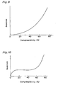
- plateau strength refers to the quotient obtained by dividing the maximum value of reaction at the plateau portion after the initial rise in the curve as shown in Figure 8 by the shock-receiving area of the shock absorber.
- absorption of compression energy refers to the quotient obtained by dividing the energy absorption, which is represented by the area under the curve as shown in Figure 8 up to the compressibility of 80% (i.e., hatched area in this figure), by the volume of the shock absorber.
- the plateau strength does not always correspond to the maximum value of stress; however, it is a value closely corresponding to the maximum stress applied to the colliding body when the shock absorber is loaded with a shock, and it serves as the standard for the maximum value of stress.
- the shock absorber of the first type preferably has a plateau strength in the range of 4.903325 x 10 5 to 4.903325 x 10 7 Pa (50 tf/m 2 to 5000 tf/m 2 ), more preferably 9.80665 x 10 5 to 1.96133 x 10 7 Pa (100 tf/m 2 to 2000 tf/m 2 ).
- plateau strength fails to give satisfactory exhibition of functions as a shock energy absorber.
- the plateau strength is too high, larger reaction is generated at the shock loading, and there arises some fear that the breakage of horizontal members, vertical members, or neighboring structures, or the bridge falling, may be caused by the reaction. Therefore, for the purpose of attaining the effective absorption of shock energy to attain cushioning effects, it is effective to make the initial rise in the load (reaction) vs. compressibility curve as steep as possible, to make the reduction in reaction after the plateau point as small as possible, and to keep the reaction at a substantially constant level, which is lower than the force breaking the neighboring or surrounding structures, up to high compressibility.
- larger shock energy can be absorbed, if the hatched portion under the curve as shown in Figure 8 takes a trapezoidal shape with a wider area.
- the absorption of compression energy should preferably be adjusted to 4.903325 x 10 5 J/m 3 (50 tf.m/m 3 ) or higher, more preferably 9.80665 x 10 5 J/m 3 (100 tf.m/m 3 ) or higher.
- conventional shock absorbers such as molded rubber parts exhibit a gentle slope for the initial rise as shown in the load (reaction) vs. compressibility curve of Figure 9, so that the satisfactory absorption of shock energy can be attained only by the use of a material in quantity, which is not preferred because of a increase both in size and in weight as the shock absorber of the first type.
- the shock absorber of the first type which can be used in the bridge of shock-absorbing construction according to the present invention, exhibits a steep slope for the initial rise in the load (reaction) vs. compressibility curve and then a suitable plateau strength, for example, as shown in Figure 10, after which it keeps the substantially constant level of reaction for some time with a rise in compressibility and then exhibits again a steep slope for the last rise in the load (reaction) vs. compressibility curve.
- the shock absorber of the first type can absorb compression energy in an extremely large amount of 4.903325 x 10 5 J/m 3 (50 tf.m/m 3 ) or higher.
- the preferred kinds of resins which can be used for the production of shock absorbers of the first type, are as described above, and these resins may be modified, if necessary, by the addition of various stabilizers such as antioxidants, ultraviolet light absorbers, and heat stabilizers; fillers such as dyes, pigments, carbon black, talc, and glass beads; reinforcing materials such as metal fibers, glass fibers, carbon fibers, and whiskers; and additives such as antistatic agents, plasticizers, flame retarders, foaming agents, and release agents in their appropriate amounts.
- stabilizers such as antioxidants, ultraviolet light absorbers, and heat stabilizers
- fillers such as dyes, pigments, carbon black, talc, and glass beads
- reinforcing materials such as metal fibers, glass fibers, carbon fibers, and whiskers
- additives such as antistatic agents, plasticizers, flame retarders, foaming agents, and release agents in their appropriate amounts.
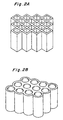
- the shock absorber of the first type which can be used in the bridge of shock-absorbing construction according to the present invention, is not limited to the specific structure as shown in Figure 1, but it may be formed into any other structure, for example, in a lattice pattern composed of many penetrating holes rectangular or rhombic in section, or in a multi-tubular pattern composed of many penetrating holes circular or elliptic in section, as shown in Figures 2A and 2B, or in a further different pattern composed of many penetrating holes having a different shape in section.
- the size of the shock absorber of the first type may be determined suitably for the purpose of use, i.e., taking into account the gap at the shock-absorbing site and the degree of a possible shock.
- There is no limitation on the formation of shock absorbers of the first type which may be achieved by any method, including injection molding, extrusion, or press molding.
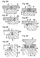
- Figures 3A through 3G show different shock absorbers of the first type, which are disposed at the points of contact between the horizontal members or between the horizontal member and the vertical member in the bridge of shock-absorbing construction according to the present invention.
- shock absorber 1 is attached to the top of vertical member 5 and interposed between the horizontal members 4, 4, which are flush with each other and supported, respectively, by bearing means 6, 6 on the vertical member 5.
- shock absorbers 1, 1 are each attached to the respective sides of ridge-shaped protrusion 5a on the top of vertical member 5 and interposed between the horizontal members 4, 4, which are flush with each other and supported, respectively, by bearing means 6, 6 on the vertical member 5.
- shock absorber 1 is attached to the side wall of L-shaped protrusion 5b on the top of vertical member 5 and interposed between the protrusion 5b and the horizontal member 4, which is supported by bearing mean 6 on the vertical member 5.
- bracket 8 is formed on the bottom of horizontal member 4, which is supported by bearing means 6 on the vertical member 5 and faced to the side wall of L-shaped protrusion 5b on the top of the vertical member 5
- safety wall 7 is formed on the side wall of the vertical member 5
- shock absorber 1 is attached to the safety wall 7 at the point of contact between the safety wall 7 and the bracket 8.
- safety wall 7 is formed on the top of vertical member 5, and shock absorber 1 is attached to the safety wall 7 at the point of contact between the safety wall 7 and the inner side wall of bottom-hollowed horizontal member 4, which is supported by bearing means 6 on the vertical member 5 and faced to the side wall of L-shaped protrusion 5b on the top of the vertical member 5.
- safety wall 7 is formed on the top of vertical member 5, and shock absorber 1 is attached to the inner side wall of bottom-hollowed horizontal member 4 at the point of contact between the safety wall 7 and the inner side wall of the bottom-hollowed horizontal member 4, which is supported by bearing means 6 on the vertical member 5 and faced to the side wall of L-shaped protrusion 5b on the top of the vertical member 5.
- shock absorbers 1, 1, ... are each attached to the respective safety walls 7b, 7b, ..., which are formed, respectively, at both edges and at the center so as to produce two parallel grooves on the top of vertical member 5, and horizontal member 4 having a reverse U-shaped portion on the bottom is supported by bearing means 6, 6 on the vertical member 5 so that the reverse U-shaped portion is fitted into the two parallel grooves and shock absorption in the transverse direction can be achieved.
- the shock absorbers of the first type having the physical properties and structure as described above, which have been disposed in a bridge at the points of contact between the horizontal members, between the horizontal member and the vertical member, or between the vertical member with a safety wall and the horizontal member, can attain effective absorption or attenuation of a shock when the bridge is shaken by earthquakes or other factors, to prevent the horizontal members, the vertical members, or the neighboring structures, from being damaged or broken by the shock, or to prevent bridge falling from happening by a drop of the horizontal members.
- the connection between the horizontal member and the vertical member, and the positions of the shock absorbers attached, as shown in Figures 3A through 3G are only typical examples, and the present invention is not particularly limited to these examples.
- a suitable method may be adopted, for example, fastening with a bolt to an embedded nut, or fixing with an appropriate fitting means.
- shock absorber of the second type which can be used in the bridge of shock-absorbing construction according to the present invention.
- the shock absorber of the second type is disposed on the connector for connecting the adjacent horizontal members or for connecting the horizontal member and the vertical member.
- the connector may be in the form of a cable- or reinforcing bar-shaped metal rod, a metal plate, or the like.
- the shock absorbers of the second type may be disposed at both ends of such a connector so as to come in direct contact with the horizontal member or the vertical member.
- the shock absorber of the second type may preferably have a plateau strength of 3.92266 x 10 6 Pa (400 tf/m 2 ) or higher, but more preferably up to 1.96133 x 10 8 Pa (20,000 tf/m 2 ), still more preferably 9.80665 x 10 6 to 9.80665 x 10 7 Pa (1000 to 10,000 tf/m 2 ), and may absorb compression energy of 1.96133 x 10 6 J/m 3 (200 tfm/m 3 ) or higher.
- the shock absorber of the second type may preferably have a cylindrical wall structure in the shock-absorbing direction.
- the shock absorber of the second type is preferably formed from a resin with an elastic modulus in flexure ranging from 1.96133 x 10 7 to 4.903325 x 10 8 Pa (200 to 5000 kgf/cm 2 ), more preferably 3.92266 x 10 7 to 4.903325 x 10 8 Pa (400 to 5000 kgf/cm 2 ), and still more preferably 6.864655 x 10 7 to 3.92266 x 10 8 Pa (700 to 4000 kgf/cm 2 ) or a material with an elastic modulus in flexure over 4.903325 x 10 8 Pa (5000 kgf/cm 2 ).
- a resin or material are the same as described for the shock absorber of the first type.
- plateau strength fails to give satisfactory exhibition of functions as a shock energy absorber. On the contrary, if the plateau strength is too high, larger reaction is generated at the shock loading, and there arises some fear that the breakage of horizontal members, vertical members, or neighboring structures, or the bridge falling, may be caused by the reaction.
- the shock absorber of the second type may preferably have at least one flange because it can be loaded with a shock uniformly on the whole and deformation in the cylindrical shape at a suitable site can attain stable and efficient shock absorption.
- the shock absorber of the second type may further preferably have a cylindrical wall structure containing such a particular portion in the shock-loading direction that causes first deformation when loaded with a shock.
- the cylindrical wall structure in the shock-loading direction may preferably be provided with a cutout portion or a thin-walled portion, or have an accordion structure.
- the shock absorber of the second type formed into such a cylindrical shape, is disposed at the end of a connector used at the point of connection between the adjacent horizontal members or between the horizontal member and the vertical member in a bridge. More particularly, the connector is inserted into the axial hollow portion of the cylindrical shock absorber of the second type, which is then fixed with an end fitting means at the end of the connector.
- the cylindrical shock absorbers of the second type may be each fixed at the respective ends of the connector.
- the end fitting portion of the connector may preferably be fixed with a bolt and a nut so that even if the shock to be attenuated by the shock absorber is loaded on the end-fitting portion there is no fear that the connector may be released or broken.
- the shock absorber of the second type may be formed into any shape, so long as it is cylindrical with an axial hollow portion (i.e., hole) into which a connector can be inserted, as illustrated below in some drawings, and it gives a load (reaction) vs. compressibility curve, as shown in Figure 8, when loaded with a compressive force.
- the cylindrical shape may be circular, polygonal, e.g., hexagonal, or any other different shape in section.
- the shock absorber of the second type may also be formed from a resin with an elastic modulus in flexure within a specific range as described above, preferably an elastomer.
- a resin with an elastic modulus in flexure within a specific range as described above, preferably an elastomer.
- shock absorbers of the second type may be achieved by any method, including injection molding, compression molding, or extrusion.
- a solid rod may be formed and then processed into a cylindrical shape by cutting or drilling.
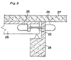
- Figures 4 and 5 show the points of connection between the adjacent horizontal members and between the horizontal member and the vertical member, respectively, in the bridge of shock-absorbing construction according to the present invention.
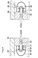
- Figure 6 shows a cable-type connector for connecting the adjacent horizontal members, on which the shock absorbers of the second type are each disposed at the respective ends.
- the bridge of shock-absorbing construction contains, for example, as shown in Figure 4, road 27 and a series of horizontal members 26, 26, which are supported, respectively, by bearing means on the vertical member 28 disposed on the top of bridge footing.
- horizontal members 26, 26 are connected with each other by cable-type connector 22 so as not to come off and fall from the vertical member 28.
- horizontal member 26 is supported by bearing means on the vertical member 28 and connected, for the prevention of its fall, by cable-type connector 22 with an L-shaped protrusion formed on the top of vertical member 28 so as to reach road 27.
- the shock absorbers of the second type are disposed, for example, as shown in Figure 6, for the-absorption of a shock loaded on the cable-type connectors 22, 22 as shown in Figures 4 and 5, to prevent these connectors and surrounding structures from being damaged or broken. More particularly, cable-type connector 22 is inserted into the penetrating holes at the facing ends of the horizontal members 26, 26 (or the horizontal member 26 and vertical member 28 as shown in Figure 5), and the ends of the cable-type connector 22 are each inserted into the respective axial hollow portions of cylindrical shock absorbers 21, 21 and fitted outside with support plats 24, 24, which are further fitted outside with washers 23', 23' and fastened with nuts 23, 23.
- the cable-type connectors 22, 22, although they are fastened tight in Figure 6, may be fitted loosely to such an extent that they can follow the slight motion of structures by temperature variation or vibration.
- elastic parts such as springs may be inserted between the support plate 24 and the nut 23 so that the cable-type connectors 22, 22 can follow the expansion and contraction of structures by temperature variation, or buffering parts other than springs may also be inserted.
- more than one cable-type connectors 22 may be disposed parallel with each other in the vertical or transverse direction, or may also be connected in series and disposed along the bridge. There is no limitation on their arrangement.
- the size or configuration of the axial hollow portion (i.e., hole) to be formed in the shock absorber 21 is not particularly limited, so long as connector 22 can be inserted thereinto. If there is too large a gap between the shock absorber 21 and the connector 22 in the axial hollow portion, also effective is the insertion of a sleeve or other auxiliary means to reduce the gap.
- the fastening portion including shock absorber 21 and bolt 23 is preferably covered with protective cover 25, as shown in Figure 6, to improve the durability and weatherability of the bridge and not to spoil the total appearance of the bridge.
- shock-absorbing constructiom according to the present invention has been explained with typical examples each using the shock absorber of the first or second type; however, the present invention is not limited to these examples.
- the shock absorber of the first type may be disposed on the connector for connecting the adjacent horizontal members, or the shock absorber of the second type may be disposed at the points of contact between the horizontal members or between the horizontal member and the vertical member.
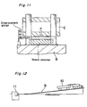
- a test machine as shown in Figure 12 was used.
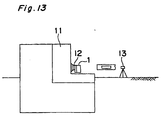
- the impact cart 10 weighing about 7 tons was allowed to run on the inclined rail 9 and to collide at the speed of 1.8 m/sec with the shock absorber 1 fixed with the load cell 12 on the collision side of the rigid block 11 as shown in Figure 13.
- the shock-absorbing performance of the shock absorber 1 was evaluated by the laser displacement gauge.
- the reference numeral 13 indicates an accelerometer.
- This is defined as the contact area between the impact cart and the shock absorber.
- the shock absorber of the first type it represents the apparent contact area as a formed part, not the real contact area on only cell walls of the formed part.
- the energy absorption per unit volume of the shock absorber was determined at the point of critical compression on the load (reaction) vs. compressibility curve where displacement reached about 0.2 mm / 9.80665 x 10 3 N (mm/tf).
- the power of destroying the rigid block was estimated at 25 tf for the impact-receiving area of the shock absorber being 500 mm x 100 mm.
- the above maximum reaction was over 25 tf, an impact was considered to be loaded on the rigid block.
- the energy absorption or the amount of energy absorbed in the shock absorber was defined as the difference of kinetic energy calculated from the speeds of the impact cart before and after the collision.
- a shock absorber with a honeycomb structure as shown in Figure 1 was prepared by injection molding with polyester elastomer "PELPRENE® P-90B" available from Toyobo.
- the wall thickness and length of one side of each hexagonal cell in the honeycomb structure were 4.3 mm and 25 mm, respectively.
- the total width, depth, and height of the shock absorber were 500 mm, 100 mm, and 100 mm, respectively.
- the performance test of the shock absorber was performed at 15°C. The results are shown, together with the physical properties of the material, in Table 1.
- a shock absorber with a honeycomb structure in the same shape and size as described in Example 1 was prepared by injection molding with polyester elastomer "PELPRENE® P-150B" available from Toyobo. The performance test of the shock absorber was performed at 40°C. The results are shown, together with the physical properties of the material, in Table 1.
- a shock absorber with a honeycomb structure as shown in Figure 1 was prepared from aluminum.
- the wall thickness and length of one side of each hexagonal cell in the honeycomb structure were 0.07 mm and 5.5 mm, respectively.
- the total width, depth, and height of the shock absorber were 500 mm, 300 mm, and 100 mm, respectively.
- the performance test of the shock absorber was performed at 15°C. The results are shown, together with the physical properties of the material, in Table 1.
- a shock absorber with a honeycomb structure as shown in Figure 1 was prepared by injection molding with nylon "T-222" available from Toyobo.
- the wall thickness and length of one side of each hexagonal cell in the honeycomb structure were 4.3 mm and 25 mm, respectively.
- the total width, depth, and height of the shock absorber were 500 mm, 30 mm, and 100 mm, respectively.
- the performance test of the shock absorber was performed at 40°C. The results are shown, together with the physical properties of the material, in Table 1.
- the total width, depth, and height of the shock absorber were 500 mm, 100 mm, and 100 mm, respectively.
- the performance test of the shock absorber was performed at 15°C. The results are shown in Table 1.
- a shock absorber with a double-flanged type cylindrical structure in the shape and size as shown in Figure 7 and in Table 2, respectively, was prepared by injection molding with nylon "T222" available from Toyobo.
- the performance test of the shock absorber was performed at 40°C. The results are shown, together with the physical properties of the material, in Table 2.
- a commercially available chloroprene rubber block of hardness 45A was cut into a shock absorber with a double-flanged type cylindrical structure in the same shape and size as described in Example 3.
- the performance test of the shock absorber was conducted at 15°C. The results are shown in Table 2.
- a commercially available chloroprene rubber block of hardness 63A was cut into a shock absorber with a double-flanged type cylindrical structure in the same shape and size as described in Example 3.
- the performance test of the shock absorber was conducted at 15°C. The results are shown in Table 2.
- the shock absorbers of Examples 1 to 6 exhibited excellent shock-absorbing performance, so that shock-absorbing construction with any of the shock absorbers can effectively absorb or attenuate the shock of collisions, by earthquakes or other factors, between the horizontal members or between the horizontal member and the vertical member, and the shock on the points of their connection through connectors. Therefore, the bridge of such shock-absorbing construction can prevent, with high reliability, the breakage or separation of horizontal members or vertical members, and the breakage of neighboring structures caused by these shocks, and can therefore sufficiently withstand to earthquakes or other factors.
- the bridge containing such shock absorbers can find various applications, including inland bridges, coastal bridges, and marine connecting bridges, even in which case the bridge is free of maintenance to retain excellent shock-absorbing performance for a long period of time.
Landscapes
- Engineering & Computer Science (AREA)
- Architecture (AREA)
- Business, Economics & Management (AREA)
- Emergency Management (AREA)
- Environmental & Geological Engineering (AREA)
- Civil Engineering (AREA)
- Structural Engineering (AREA)
- Bridges Or Land Bridges (AREA)
- Vibration Dampers (AREA)
- Buildings Adapted To Withstand Abnormal External Influences (AREA)
- Transition And Organic Metals Composition Catalysts For Addition Polymerization (AREA)
- Joining Of Building Structures In Genera (AREA)
Abstract
Description
- The present invention relates to a bridge of novel shock-absorbing construction. More particularly, it relates to a bridge of shock-absorbing construction in which shock absorbers are disposed at the points of contact between the horizontal members or between the horizontal member and the vertical member and on the connectors for connecting the adjacent horizontal members or for connecting the horizontal member and the vertical member to ensure the effective absorption or attenuation of a shock. For example, when shaken by an earthquake, a bridge of such construction can effectively absorb or attenuate the shock of collisions between the horizontal members or between the horizontal member and the vertical member to prevent these members from being damaged and further to prevent the horizontal member from falling from the vertical member.
- Most of the bridge fallings caused by a shock such as an earthquake are due to the breakage or separation of members by the shock of collisions at the points of connection between the adjacent horizontal members or between the horizontal member and the vertical member in the bridge. This fact was confirmed in the Great Hanshin-Awaji Earthquake of 1995.
- For the prevention of bridge fallings, various methods have hitherto been adopted, including the formation of a slippage-preventive protrusion (i.e., bracket) or a bridge falling-preventive wall (i.e., safety wall) on the top of a vertical member or on the bottom of a horizontal member; the connection between the horizontal member and the vertical member by PC steel parts or anchor bars; and connection between the adjacent horizontal members by PC steel parts.
- In the breakage or falling of bridges as previously investigated in the earthquake disasters of the past, there have been often found damage caused by vertical displacement to the bridge axis and damage probably caused by shock vibration. For this reason, most of the bridge falling-preventive construction now in practical use involves both connecting construction that can follow the vertical movement to the bridge axis and shock-absorbing construction with shock absorbers for absorbing or attenuating the shock vibration.
- The shock absorber which has been used in the bridge of such shock-absorbing construction may include molded rubber parts characterized by good restitution. In the case where shock absorbers are disposed at very limited sites such as points of connection between the adjacent horizontal members or between the horizontal member and the vertical member, the use of molded rubber parts gives a limitation on the size of shock absorbers, leading to a deterioration in the shock-absorbing performance, which makes it difficult to obtain satisfactory effects on the prevention of breakage or falling of bridges against strong and shock vibration. The shock absorption may also be increased by the use of molded rubber parts made thicker or by the combined use of more than one molded rubber part, in which either case, however, the shock absorbers become large-sized, so that they are difficult to dispose at very limited sites, in addition to a steep rise in material costs and an increase in weight.
- Some shock absorbers other than molded rubber parts have also been known, for example, metal springs, shock-attenuating friction members, and shock-attenuating hydraulic members. Metal springs, although they have excellent shock-absorbing performance, have an inevitable problem of rust formation; therefore, elaborate maintenance is needed after construction and, from a viewpoint of resistance to rust and weather, they are not suitable for use in the bridges to be constructed at locations exposed to salt water, such as coastal bridges and marine connecting bridges. In general, friction or hydraulic shock-attenuating members are structurally complicated and both much expensive and heavy, and they cannot keep their original performance without undergoing proper maintenance.
- As the shock absorbers using molded resin parts, Japanese Patent Publication No. 61-12779/1986 discloses a technique for the improvement of shock-absorbing performance where hollow molded parts of a thermoplastic resin elastomer are provided with permanent strain by pre-compression in the axial direction. However, such molded resin parts, although they have improved ability to function as an elastic body, have poor performance of absorbing the energy of compression, so that they cannot be expected to have satisfactory shock-absorbing performance for use in the prevention of bridge falling caused by earthquakes or other factors.
- CA-A-1206981 discloses a deflection control device in which viscoelastic discs are first compressed to damp relative movement and thereafter during excessive movement the viscous material is extruded through perforations to absorb energy. In such a structure there is no intentional buckling or permanent deformation of the wall elements. GB-A-1084064 discloses a foundation arrangement for protecting buildings in which the foundation arrangement bears the load of the building in the vertical direction.
- Further, GB-A-2305487 disclosed an impact energy absorber having a low initial load which is constructed from stainless steel honeycomb sections and is formed into a cuboid shape with axes of the honeycomb cells parallel to one axis of the cuboid. EP-A-0705994 discloses an impact energy absorptive structure which is made of plastic materials suitable for moulding processing, and is designed to suit different degrees of impact loading.
- The present inventors have developed a shock absorber formed from an elastic resin, comprising more than one arch-, dome-, or honeycomb-shaped member capable of causing deformation by compression, which are disposed on a perforated or non-perforated flat plate of an elastic resin, and thereby having cushioning properties; and they have proceeded with various studies to put such a shock absorber to practical use. This type of shock absorbers is suitable for some applications in which they are widely spread over the side wall of a road or the floor of a building to exhibit uniform cushioning performance over a wide area; however, they are difficult to adopt some applications in which they have to be disposed at limited sites such as points of connection between the adjacent horizontal members or between the horizontal member and the vertical member, and they cannot exhibit satisfactory shock-absorbing performance.
- The shock absorbers in the bridge construction are often disposed in the vicinity of horizontal member-bearing portions on the vertical members; therefore, they should not become an obstacle to the maintenance works of the bearing portions, such as inspection, conservation, and repair. Therefore, they are required to be small-sized and lightweight, and have excellent shock-absorbing performance, i.e., higher absorption of energy of compression rather than reaction; however, the conventional shock absorbers as described above cannot meet these requirements.
- It is an object of the present invention to provide an improved bridge or shock absorber. This object is achieved with the subject matter of the claims.
- Under these circumstances, the present inventors have surprisingly found a shock absorber for use in bridges, which is small-sized and lightweight, has a simple construction, and exhibits higher absorption of energy of compression rather than reaction, and wherein if it is formed from a material with excellent rust resistance, water resistance, and weatherability, the bridge containing such shock absorbers can find various practical applications, including inland bridges, coastal bridges, and marine connecting bridges, even in which case the bridge is free of maintenance to retain excellent shock-absorbing performance for a long period of time. As a result, they have found that the use of such a shock absorber makes it possible to prevent, with high reliability, the breakage of horizontal members or vertical members, or the falling of the horizontal members from the vertical members, by a shock such as an earthquake, thereby completing the present invention.
- Thus, the present invention provides a bridge of shock-absorbing construction, comprising horizontal members arranged in series, vertical members supporting the horizontal members, and connectors for connecting the adjacent horizontal members or for connecting the horizontal member and the vertical member, wherein shock absorbers formed from a material with an elastic modulus in flexure over 1.96133 x 10⁷ Pa (200 kgf/cm2) and each having a wall structure in a shock-loading direction are disposed on the connectors or at the points of contact between the horizontal members or between the horizontal member and the vertical member. For the effective absorption of large energy by a shock, the shock absorber preferably causes buckling deformation or permanent deformation in the wall structure by compression when loaded with the shock.
- The above and still further objects, features, and advantages of the present invention will become apparent upon consideration of the following preferred embodiments exemplified in the description of the invention, especially when taken in conjunction with the accompanying drawings wherein like reference numerals in various figures are utilized to designate like portions, and wherein:
- Figure 1 is a perspective view showing a typical example of the shock absorber of the first type, which can be used in the bridge of shock-absorbing construction according to the present invention.
- Figures 2A and 2B are perspective views showing different examples of the shock absorber of the first type, which can be used in the bridge of shock-absorbing construction according to the present invention.
- Figures 3A through 3G are sectional fragmentary schematic views showing various shock absorbers of the first type, which are disposed at the points of contact between the horizontal members or between the horizontal member and the vertical member in the bridge of shock-absorbing construction according to the present invention.
- Figures 4 and 5 are sectional fragmentary schematic views showing the cable-type connectors for connecting the adjacent horizontal members and for connecting the horizontal member and the vertical member, respectively, in the bridge of shock-absorbing construction according to the present invention.
- Figure 6 is a sectional fragmentary schematic view showing a typical example of the shock absorbers of the second type, which are disposed at the ends of a cable-type connector for connecting the adjacent horizontal members in the bridge of shock-absorbing construction according to the present invention.
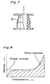
- Figure 7 is a partly sectional side view showing a specific example of the shock absorber of the second type, which can be used in the bridge of shock-absorbing construction according to the present invention.
- Figure 8 is a graph showing a typical example of the load (reaction) vs. compressibility curve of a shock absorber which can be used in the bridge of shock-absorbing construction according to the present invention.
- Figure 9 is a graph showing the load (reaction) vs. compressibility curve of conventional rubber molded parts.
- Figure 10 is a graph showing the load (reaction) vs. compressibility curve of a shock absorber which can be used in the bridge of shock-absorbing construction according to the present invention.
- Figure 11 is a fragmentary schematic view showing a static compression test machine used in the working examples and comparative examples as described below.
- Figure 12 is a schematic view showing a shock test machine used in the working examples and comparative examples as described below.
- Figure 13 is an enlarged schematic view showing the shock absorber arranged in such a manner as illustrated in Figure 12.
-
- The bridge of shock-absorbing construction according to the present invention contains horizontal members arranged in series, vertical members supporting the horizontal members and each optionally having a safety wall, and connectors for connecting the adjacent horizontal members or for connecting the horizontal member and the vertical member, wherein shock absorbers are disposed on the connectors and at the points of contact between the horizontal members or between the horizontal member and the vertical member.
- The use of particular shock absorbers in a bridge makes it possible to attain effective absorption or attenuation of a shock loaded on the points of contact between the constitutive members of the bridge, for example, by an earthquake, so that the protective portions of the bridge or the neighboring structures can be prevented from being damaged or broken by the shock, and accidental fallings of the horizontal members from the vertical members, i.e., bridge falling accidents, can be prevented from happening.
- The shock absorber has to be formed from a material with an elastic modulus in flexure over 1.96133 x 10⁷ Pa (200 kgf/cm2), preferably 4.903325 x 10⁷ Pa (500 kgf/cm2), and has a wall structure in a shock-loading direction. The term "wall structure in a shock-loading direction" as used herein refers to a wall structure provided substantially parallel to a shock-loading direction. If a shock absorber is formed from a material with an elastic modulus in flexure lower than 1.96133 x 10⁷ Pa (200 kgf/cm2), it has insufficient stiffness, so that it causes immediate elastic deformation when loaded with a shock. In other words, the shock absorber exhibits a decrease in the absorption of shock energy, so that it cannot sufficiently absorb the shock, making it impossible to obtain satisfactory cushioning effects. To solve this problem, a thicker wall structure in the shock-loading direction is needed for the shock absorber. As a result, a shock absorber should be made larger in size, which is not preferred with a departure from the purpose of the present invention.
- It is important that the shock absorber causes buckling deformation or permanent deformation in the wall structure by compression when loaded with a shock, thereby attaining effective shock absorption. Therefore, a shock absorber is not preferred to have such a structure that absorbs a shock only by its elastic deformation. This is because when sudden large shocks, such as earthquakes, are loaded on the shock absorber with such a structure several times or some dozens of times for a short period of time, the shock absorber cannot have sufficient energy-absorbing performance or may sometimes cause a resonance phenomenon and rather increase the vibration of the horizontal members of a bridge, thereby quickening the breakage of the bridge structure.
- The shapes of shock absorbers used in the bridge of shock-absorbing construction according to the present invention are roughly divided into the following two types.
- One is a shock absorber having such a shape that can absorb a shock on the fairly large area thereof (hereinafter referred to as the shock absorber of the first type). The shock absorber of the first type is mainly disposed at the point of contact between the horizontal members or between the horizontal member and the vertical member. For the vertical member with a safety wall, the shock absorber of the first type may be disposed either on the safety wall or on the inner side wall of the horizontal member so that the inner side wall of the horizontal member is not brought into direct contact with the safety wall. The other is a shock absorber of relatively small size, which is mainly disposed on the connector for connecting the adjacent horizontal members or for connecting the horizontal member and the vertical member (hereinafter referred to as the shock absorber of the second type).
- The shock absorber of the first type is characterized in that it has a multiple wall structure in a shock-loading direction. The shock absorber of the first type preferably has a cell structure in which a plurality of cells are joined together through at least a part of each cell wall along the shockloading direction and isolated from each other in the shock-loading direction. The cells in the cell structure may be composed of penetrating holes open at both ends, concave cavities open only at one end, or hollow cavities closed at both ends.
- When the shock absorber of the first type with such a cell structure is loaded with a shock, the wall structure in the shock-loading direction, which is composed of cell walls in the cell structure, causes buckling deformation to take an accordion shape, thereby attaining effective shock absorption.
- To secure sufficient shock-absorbing performance that can cope with sudden shocks, for example, by earthquakes, the shock absorber of the first type can preferably absorb compression energy of 4.903325 x 10⁵ J/m3 (50 tf.m/m3) or higher when compressed by these shocks in the shock-loading direction. This performance is achieved bv the use of a resin with an elastic modulus in flexure ranging from 4.903325 x 10⁷ to 2.6477955 x 10¹⁰ Pa (500 to 270,000 kgf/cm2), preferably 4.903325 x 10⁷ to 1.96133 x 10⁹ Pa (500 to 20,000 kgf/cm2), or more preferably 7.84532 x 10⁷ to 3.92266 x 10⁸ Pa (800 to 4000 kgf/cm2), or by the use of a material with an elastic modulus in flexure over 4.903325 x 10⁸ Pa (5000 kgf/cm2).
- The shock absorber of the first type may be formed from any natural or synthetic elastic resin, so long as the resin meets the above condition on the elastic modulus in flexure. Specific examples of the resin preferably used are thermoplastic polyester elastomers, polyolefin elastomers, polyurethane elastomers, and polyamide elastomers, including their blends in any ratio, and thermosetting resins such as polyurethane resins for use in the casting. Particularly preferred are thermoplastic polyester elastomers and polyolefin elastomers because of their excellent weatherability and water resistance.
- The shock absorber of the first type may also be formed from any material, so long as the material meets the above condition on the elastic modulus in flexure. The use of a material with excellent rust preventing properties and water resistance is preferred. Specific examples of such a material are thermoplastic resins and thermosetting resins; thermoplastic resins and thermosetting resins, each reinforced with fillers (e.g., carbon black, talc, glass beads), fibrous reinforcing materials (e.g., metal fibers, glass fibers, carbon fibers), or whiskers; and metals such as iron, aluminum, nickel, copper, titanium, zinc, tin, lead, aluminum alloys (e.g., duralumin), brass, and stainless steel. Particularly preferred metals are aluminum, copper, brass, duralumin, and stainless steel because of their excellent weatherability and water resistance.
- In the case of the shock absorber of the first type, which is formed from such a resin or material, the rise of reaction at a time when the cells serving as escape spaces become smaller with the development of buckling deformation may sometimes become too steep. To solve this problem, the cells may be filled with other cushioning materials such as foamable resins or rubber.
- The shock absorber of the first type can have further improved initial shock-absorbing performance by the adoption of a wall structure containing such a particular portion in the shock-loading direction that causes first deformation when loaded with a shock. In this case, the wall structure in the shock-loading direction may preferably be provided with a cutout portion, a stepped portion, or a thin-walled portion. When loaded with a shock, the shock absorber of the first type causes immediate deformation in such a particular portion, so that the initial shock-absorbing performance can be improved and the reaction to the shock can be further reduced.
- For attaining efficient absorption of energy, the cell structure of the shock absorber preferably has a hexagonal or lower polygonal pattern in a section perpendicular to the shock-loading direction. More preferably, it is a honeycomb structure with a hexagonal pattern.
- The shock absorber of the second type may have a plateau strength of 400 tf/m2 or higher and absorbs compression energy of 1.96133 x 10⁶ J/m3 (200 tfm/m3) or higher, and the shock absorber of the second type has a cylindrical wall structure in the shock-absorbing direction. To meet these conditions, the shock absorber of the second type is preferably formed from a resin with an elastic modulus in flexure ranging from 1.96133 x 10⁷ to 4.903325 x 10⁸ Pa (200 to 5000 kgf/cm2), or a material with an elastic modulus in flexure over 4.903325 x 10⁸ Pa (5000 kgf/cm2).
- The shock absorber of the second type may preferably have at least one flange. In addition, the shock absorber of the second type may preferably have a cylindrical wall structure containing such a particular portion in the shock-loading direction that causes first deformation when loaded with a shock. In this case, the cylindrical wall structure in the shock-loading direction may preferably be provided with a cutout portion or a thin-walled portion, or have an accordion structure.
- The shock absorber of the second type is mainly disposed at the end of a connector for connecting the adjacent horizontal members or for connecting the horizontal member and the vertical member. The connector preferably runs through the shock absorber of the second type. In addition, the connector is preferably a connection cable, i.e., cable-type connector.
- The following will give a typical example of the shock absorber of the first type, which can be used in the bridge of shock-absorbing construction according to the present invention, and the mechanism of shock absorption will be explained in detail.
- Figure 1 is a perspective view showing a typical example of the shock absorber of the first type, i.e., a shock absorber with a honeycomb structure, which has been integrally formed from an elastic resin meeting the above condition on the elastic modulus in flexure. In this figure,
shock absorber 1 has a cell structure that is composed of many penetratingholes cell walls holes - More particularly, the shock absorber of the first type as shown in Figure 1 can absorb a shock by the inherent elasticity of
cell walls holes cell walls holes cell walls holes - The satisfactory shock-absorbing performance as a shock absorber can preferably be attained by the absorption of compression energy adjusted to 4.903325 x 10⁵ J/m3 (50 tf.m/m3) or higher, more preferably 9.80665 x 10⁵ J/m3 (100 tf.m/m3) or higher, as determined by a load (reaction) vs. compressibility curve, which is obtained for example, when the shock absorber of the first type as shown in Figure 1 is compressed in the holes-running direction (i.e., in the direction of the thick arrow shown in this figure).
- The term "load (reaction) vs. compressibility curve" as used herein refers to a curve showing the correlation between load (reaction) observed in the compression of a shock absorber and compressibility. For example, as shown in Figure 8, the load (reaction) vs. compressibility curve steeply rises in proportion to compressibility at the initial stage of compression. After that, the slope of the curve gradually becomes gentle and the load (reaction) becomes substantially constant with a rise in compressibility; therefore, the curve reaches a plateau point showing the maximum value of reaction in a limited portion. When the shock absorber is further compressed,
cell walls holes cell walls holes - The term "plateau strength" as used herein refers to the quotient obtained by dividing the maximum value of reaction at the plateau portion after the initial rise in the curve as shown in Figure 8 by the shock-receiving area of the shock absorber. The term "absorption of compression energy" as used herein refers to the quotient obtained by dividing the energy absorption, which is represented by the area under the curve as shown in Figure 8 up to the compressibility of 80% (i.e., hatched area in this figure), by the volume of the shock absorber. The plateau strength does not always correspond to the maximum value of stress; however, it is a value closely corresponding to the maximum stress applied to the colliding body when the shock absorber is loaded with a shock, and it serves as the standard for the maximum value of stress.
- The shock absorber of the first type preferably has a plateau strength in the range of 4.903325 x 10⁵ to 4.903325 x 10⁷ Pa (50 tf/m2 to 5000 tf/m2), more preferably 9.80665 x 10⁵ to 1.96133 x 10⁷ Pa (100 tf/m2 to 2000 tf/m2).
- The shortage of plateau strength fails to give satisfactory exhibition of functions as a shock energy absorber. On the contrary, if the plateau strength is too high, larger reaction is generated at the shock loading, and there arises some fear that the breakage of horizontal members, vertical members, or neighboring structures, or the bridge falling, may be caused by the reaction. Therefore, for the purpose of attaining the effective absorption of shock energy to attain cushioning effects, it is effective to make the initial rise in the load (reaction) vs. compressibility curve as steep as possible, to make the reduction in reaction after the plateau point as small as possible, and to keep the reaction at a substantially constant level, which is lower than the force breaking the neighboring or surrounding structures, up to high compressibility. In other words, larger shock energy can be absorbed, if the hatched portion under the curve as shown in Figure 8 takes a trapezoidal shape with a wider area.
- In view of this point, various studies have been made on the physical properties needed for the shock absorber of the first type, which can be used in the bridge of shock-absorbing construction according to the present invention. As a result, it has been confirmed that for the sufficient absorption of a shock and hence the effective prevention of horizontal members or vertical members from being damaged or broken, as described above, the absorption of compression energy should preferably be adjusted to 4.903325 x 10⁵ J/m3 (50 tf.m/m3) or higher, more preferably 9.80665 x 10⁵ J/m3 (100 tf.m/m3) or higher. In the meantime conventional shock absorbers such as molded rubber parts exhibit a gentle slope for the initial rise as shown in the load (reaction) vs. compressibility curve of Figure 9, so that the satisfactory absorption of shock energy can be attained only by the use of a material in quantity, which is not preferred because of a increase both in size and in weight as the shock absorber of the first type.
- On the other hand, the shock absorber of the first type, which can be used in the bridge of shock-absorbing construction according to the present invention, exhibits a steep slope for the initial rise in the load (reaction) vs. compressibility curve and then a suitable plateau strength, for example, as shown in Figure 10, after which it keeps the substantially constant level of reaction for some time with a rise in compressibility and then exhibits again a steep slope for the last rise in the load (reaction) vs. compressibility curve. As a result, in combination with the inherent elastic modulus in flexure of a material, the shock absorber of the first type can absorb compression energy in an extremely large amount of 4.903325 x 10⁵ J/m3 (50 tf.m/m3) or higher.
- The preferred kinds of resins, which can be used for the production of shock absorbers of the first type, are as described above, and these resins may be modified, if necessary, by the addition of various stabilizers such as antioxidants, ultraviolet light absorbers, and heat stabilizers; fillers such as dyes, pigments, carbon black, talc, and glass beads; reinforcing materials such as metal fibers, glass fibers, carbon fibers, and whiskers; and additives such as antistatic agents, plasticizers, flame retarders, foaming agents, and release agents in their appropriate amounts.
- The shock absorber of the first type, which can be used in the bridge of shock-absorbing construction according to the present invention, is not limited to the specific structure as shown in Figure 1, but it may be formed into any other structure, for example, in a lattice pattern composed of many penetrating holes rectangular or rhombic in section, or in a multi-tubular pattern composed of many penetrating holes circular or elliptic in section, as shown in Figures 2A and 2B, or in a further different pattern composed of many penetrating holes having a different shape in section. The size of the shock absorber of the first type may be determined suitably for the purpose of use, i.e., taking into account the gap at the shock-absorbing site and the degree of a possible shock. There is no limitation on the formation of shock absorbers of the first type, which may be achieved by any method, including injection molding, extrusion, or press molding.
- Figures 3A through 3G show different shock absorbers of the first type, which are disposed at the points of contact between the horizontal members or between the horizontal member and the vertical member in the bridge of shock-absorbing construction according to the present invention. In Figure 3A,
shock absorber 1 is attached to the top ofvertical member 5 and interposed between thehorizontal members means vertical member 5. In Figure 3B,shock absorbers protrusion 5a on the top ofvertical member 5 and interposed between thehorizontal members means vertical member 5. In Figure 3C,shock absorber 1 is attached to the side wall of L-shapedprotrusion 5b on the top ofvertical member 5 and interposed between theprotrusion 5b and thehorizontal member 4, which is supported by bearing mean 6 on thevertical member 5. In Figure 3D,bracket 8 is formed on the bottom ofhorizontal member 4, which is supported by bearing means 6 on thevertical member 5 and faced to the side wall of L-shapedprotrusion 5b on the top of thevertical member 5,safety wall 7 is formed on the side wall of thevertical member 5, andshock absorber 1 is attached to thesafety wall 7 at the point of contact between thesafety wall 7 and thebracket 8. In Figure 3E,safety wall 7 is formed on the top ofvertical member 5, andshock absorber 1 is attached to thesafety wall 7 at the point of contact between thesafety wall 7 and the inner side wall of bottom-hollowedhorizontal member 4, which is supported by bearing means 6 on thevertical member 5 and faced to the side wall of L-shapedprotrusion 5b on the top of thevertical member 5. In Figure 3F,safety wall 7 is formed on the top ofvertical member 5, andshock absorber 1 is attached to the inner side wall of bottom-hollowedhorizontal member 4 at the point of contact between thesafety wall 7 and the inner side wall of the bottom-hollowedhorizontal member 4, which is supported by bearing means 6 on thevertical member 5 and faced to the side wall of L-shapedprotrusion 5b on the top of thevertical member 5. In Figure 3G,shock absorbers respective safety walls vertical member 5, andhorizontal member 4 having a reverse U-shaped portion on the bottom is supported by bearing means 6, 6 on thevertical member 5 so that the reverse U-shaped portion is fitted into the two parallel grooves and shock absorption in the transverse direction can be achieved. - In this way, the shock absorbers of the first type, having the physical properties and structure as described above, which have been disposed in a bridge at the points of contact between the horizontal members, between the horizontal member and the vertical member, or between the vertical member with a safety wall and the horizontal member, can attain effective absorption or attenuation of a shock when the bridge is shaken by earthquakes or other factors, to prevent the horizontal members, the vertical members, or the neighboring structures, from being damaged or broken by the shock, or to prevent bridge falling from happening by a drop of the horizontal members. It is to be understood that the connection between the horizontal member and the vertical member, and the positions of the shock absorbers attached, as shown in Figures 3A through 3G are only typical examples, and the present invention is not particularly limited to these examples. In addition, there is no limitation on the attachment of a shock absorber, and a suitable method may be adopted, for example, fastening with a bolt to an embedded nut, or fixing with an appropriate fitting means.
- The following gives a detailed explanation of the shock absorber of the second type, which can be used in the bridge of shock-absorbing construction according to the present invention.
- The shock absorber of the second type is disposed on the connector for connecting the adjacent horizontal members or for connecting the horizontal member and the vertical member. The connector may be in the form of a cable- or reinforcing bar-shaped metal rod, a metal plate, or the like. The shock absorbers of the second type may be disposed at both ends of such a connector so as to come in direct contact with the horizontal member or the vertical member.
- The shock absorber of the second type may preferably have a plateau strength of 3.92266 x 10⁶ Pa (400 tf/m2) or higher, but more preferably up to 1.96133 x 10⁸ Pa (20,000 tf/m2), still more preferably 9.80665 x 10⁶ to 9.80665 x 10⁷ Pa (1000 to 10,000 tf/m2), and may absorb compression energy of 1.96133 x 10⁶ J/m3 (200 tfm/m3) or higher. The shock absorber of the second type may preferably have a cylindrical wall structure in the shock-absorbing direction. To meet these conditions, the shock absorber of the second type is preferably formed from a resin with an elastic modulus in flexure ranging from 1.96133 x 10⁷ to 4.903325 x 10⁸ Pa (200 to 5000 kgf/cm2), more preferably 3.92266 x 10⁷ to 4.903325 x 10⁸ Pa (400 to 5000 kgf/cm2), and still more preferably 6.864655 x 10⁷ to 3.92266 x 10⁸ Pa (700 to 4000 kgf/cm2) or a material with an elastic modulus in flexure over 4.903325 x 10⁸ Pa (5000 kgf/cm2). Examples of such a resin or material are the same as described for the shock absorber of the first type.
- The shortage of plateau strength fails to give satisfactory exhibition of functions as a shock energy absorber. On the contrary, if the plateau strength is too high, larger reaction is generated at the shock loading, and there arises some fear that the breakage of horizontal members, vertical members, or neighboring structures, or the bridge falling, may be caused by the reaction.
- The shock absorber of the second type may preferably have at least one flange because it can be loaded with a shock uniformly on the whole and deformation in the cylindrical shape at a suitable site can attain stable and efficient shock absorption.
- The shock absorber of the second type may further preferably have a cylindrical wall structure containing such a particular portion in the shock-loading direction that causes first deformation when loaded with a shock. In this case, the cylindrical wall structure in the shock-loading direction may preferably be provided with a cutout portion or a thin-walled portion, or have an accordion structure.
- The shock absorber of the second type, formed into such a cylindrical shape, is disposed at the end of a connector used at the point of connection between the adjacent horizontal members or between the horizontal member and the vertical member in a bridge. More particularly, the connector is inserted into the axial hollow portion of the cylindrical shock absorber of the second type, which is then fixed with an end fitting means at the end of the connector. The cylindrical shock absorbers of the second type may be each fixed at the respective ends of the connector. When the connector is loaded with a shock, the shock absorber of the second type causes buckling deformation to exhibit a function of absorbing the shock and attenuating a stress on the connector.
- In this case, the end fitting portion of the connector may preferably be fixed with a bolt and a nut so that even if the shock to be attenuated by the shock absorber is loaded on the end-fitting portion there is no fear that the connector may be released or broken.
- The shock absorber of the second type may be formed into any shape, so long as it is cylindrical with an axial hollow portion (i.e., hole) into which a connector can be inserted, as illustrated below in some drawings, and it gives a load (reaction) vs. compressibility curve, as shown in Figure 8, when loaded with a compressive force. The cylindrical shape may be circular, polygonal, e.g., hexagonal, or any other different shape in section. Furthermore, there is no limitation on the shape of an axial hollow portion.
- The shock absorber of the second type may also be formed from a resin with an elastic modulus in flexure within a specific range as described above, preferably an elastomer. There is no limitation on the formation of shock absorbers of the second type, which may be achieved by any method, including injection molding, compression molding, or extrusion. In some cases, a solid rod may be formed and then processed into a cylindrical shape by cutting or drilling.
- Figures 4 and 5 show the points of connection between the adjacent horizontal members and between the horizontal member and the vertical member, respectively, in the bridge of shock-absorbing construction according to the present invention. Figure 6 shows a cable-type connector for connecting the adjacent horizontal members, on which the shock absorbers of the second type are each disposed at the respective ends.
- The bridge of shock-absorbing construction according to the present invention contains, for example, as shown in Figure 4,
road 27 and a series ofhorizontal members vertical member 28 disposed on the top of bridge footing. In Figure 4,horizontal members type connector 22 so as not to come off and fall from thevertical member 28. In Figure 5,horizontal member 26 is supported by bearing means on thevertical member 28 and connected, for the prevention of its fall, by cable-type connector 22 with an L-shaped protrusion formed on the top ofvertical member 28 so as to reachroad 27. - The shock absorbers of the second type are disposed, for example, as shown in Figure 6, for the-absorption of a shock loaded on the cable-
type connectors type connector 22 is inserted into the penetrating holes at the facing ends of thehorizontal members 26, 26 (or thehorizontal member 26 andvertical member 28 as shown in Figure 5), and the ends of the cable-type connector 22 are each inserted into the respective axial hollow portions ofcylindrical shock absorbers support plats nuts - The cable-
type connectors support plate 24 and thenut 23 so that the cable-type connectors horizontal member 26, more than one cable-type connectors 22 may be disposed parallel with each other in the vertical or transverse direction, or may also be connected in series and disposed along the bridge. There is no limitation on their arrangement. - The size or configuration of the axial hollow portion (i.e., hole) to be formed in the
shock absorber 21 is not particularly limited, so long asconnector 22 can be inserted thereinto. If there is too large a gap between theshock absorber 21 and theconnector 22 in the axial hollow portion, also effective is the insertion of a sleeve or other auxiliary means to reduce the gap. Furthermore, the fastening portion includingshock absorber 21 andbolt 23 is preferably covered withprotective cover 25, as shown in Figure 6, to improve the durability and weatherability of the bridge and not to spoil the total appearance of the bridge. - The shock-absorbing constructiom according to the present invention has been explained with typical examples each using the shock absorber of the first or second type; however, the present invention is not limited to these examples. In addition, the shock absorber of the first type may be disposed on the connector for connecting the adjacent horizontal members, or the shock absorber of the second type may be disposed at the points of contact between the horizontal members or between the horizontal member and the vertical member.
- The present invention will be further illustrated by the following working examples and comparative examples; however, it is, of course, to be understood that the present invention is not limited to these examples and any other variations, modifications, and changes fall within the scope of the present invention as defined by the appended claims.
- It is substantially impossible to examine the performance of shock absorbers by disposing them at the points of contact between the horizontal members or between the horizontal member and the vertical member and then actually shaking the horizontal members. In the following working examples and comparative examples, therefore, experiments were performed by the simulation of such conditions. The determination of physical properties and the compression test both adopted in the experiments were carried out by the following procedures.
- This was determined according to the widely adopted procedures of
- A test machine as shown in Figure 12 was used. The
impact cart 10 weighing about 7 tons was allowed to run on theinclined rail 9 and to collide at the speed of 1.8 m/sec with theshock absorber 1 fixed with theload cell 12 on the collision side of therigid block 11 as shown in Figure 13. The shock-absorbing performance of theshock absorber 1 was evaluated by the laser displacement gauge. Thereference numeral 13 indicates an accelerometer. - This is defined as the contact area between the impact cart and the shock absorber. For the shock absorber of the first type, it represents the apparent contact area as a formed part, not the real contact area on only cell walls of the formed part.
- This is determined by dividing the maximum value of reaction at the plateau portion after the initial rise in the load (reaction) vs. compressibility curve as shown in Figure 8 by the shock-receiving area of the shock absorber.
- The energy absorption per unit volume of the shock absorber was determined at the point of critical compression on the load (reaction) vs. compressibility curve where displacement reached about 0.2 mm / 9.80665 x 10³ N (mm/tf).
- In the above collisional compression test, the maximum reaction generated by the collision between the impact cart and the shock absorber was determined.
- In the above collisional compression test, the maximum displacement by compression observed in the collision between the impact cart and the shock absorber was determined.
- In the above collisional compression test, the power of destroying the rigid block was estimated at 25 tf for the impact-receiving area of the shock absorber being 500 mm x 100 mm. When the above maximum reaction was over 25 tf, an impact was considered to be loaded on the rigid block.
- The energy absorption or the amount of energy absorbed in the shock absorber was defined as the difference of kinetic energy calculated from the speeds of the impact cart before and after the collision.
- A shock absorber with a honeycomb structure as shown in Figure 1 was prepared by injection molding with polyester elastomer "PELPRENE® P-90B" available from Toyobo. The wall thickness and length of one side of each hexagonal cell in the honeycomb structure were 4.3 mm and 25 mm, respectively. The total width, depth, and height of the shock absorber were 500 mm, 100 mm, and 100 mm, respectively. The performance test of the shock absorber was performed at 15°C. The results are shown, together with the physical properties of the material, in Table 1.
- A shock absorber with a honeycomb structure in the same shape and size as described in Example 1 was prepared by injection molding with polyester elastomer "PELPRENE® P-150B" available from Toyobo. The performance test of the shock absorber was performed at 40°C. The results are shown, together with the physical properties of the material, in Table 1.
- A shock absorber with a honeycomb structure as shown in Figure 1 was prepared from aluminum. The wall thickness and length of one side of each hexagonal cell in the honeycomb structure were 0.07 mm and 5.5 mm, respectively. The total width, depth, and height of the shock absorber were 500 mm, 300 mm, and 100 mm, respectively. The performance test of the shock absorber was performed at 15°C. The results are shown, together with the physical properties of the material, in Table 1.
- A shock absorber with a honeycomb structure as shown in Figure 1 was prepared by injection molding with nylon "T-222" available from Toyobo. The wall thickness and length of one side of each hexagonal cell in the honeycomb structure were 4.3 mm and 25 mm, respectively. The total width, depth, and height of the shock absorber were 500 mm, 30 mm, and 100 mm, respectively. The performance test of the shock absorber was performed at 40°C. The results are shown, together with the physical properties of the material, in Table 1.
- A commercially available chloroprene rubber plate of hardness 63A, widely used as a cushioning material, was cut into a solid bar as a shock absorber. The total width, depth, and height of the shock absorber were 500 mm, 100 mm, and 100 mm, respectively. The performance test of the shock absorber was performed at 15°C. The results are shown in Table 1.
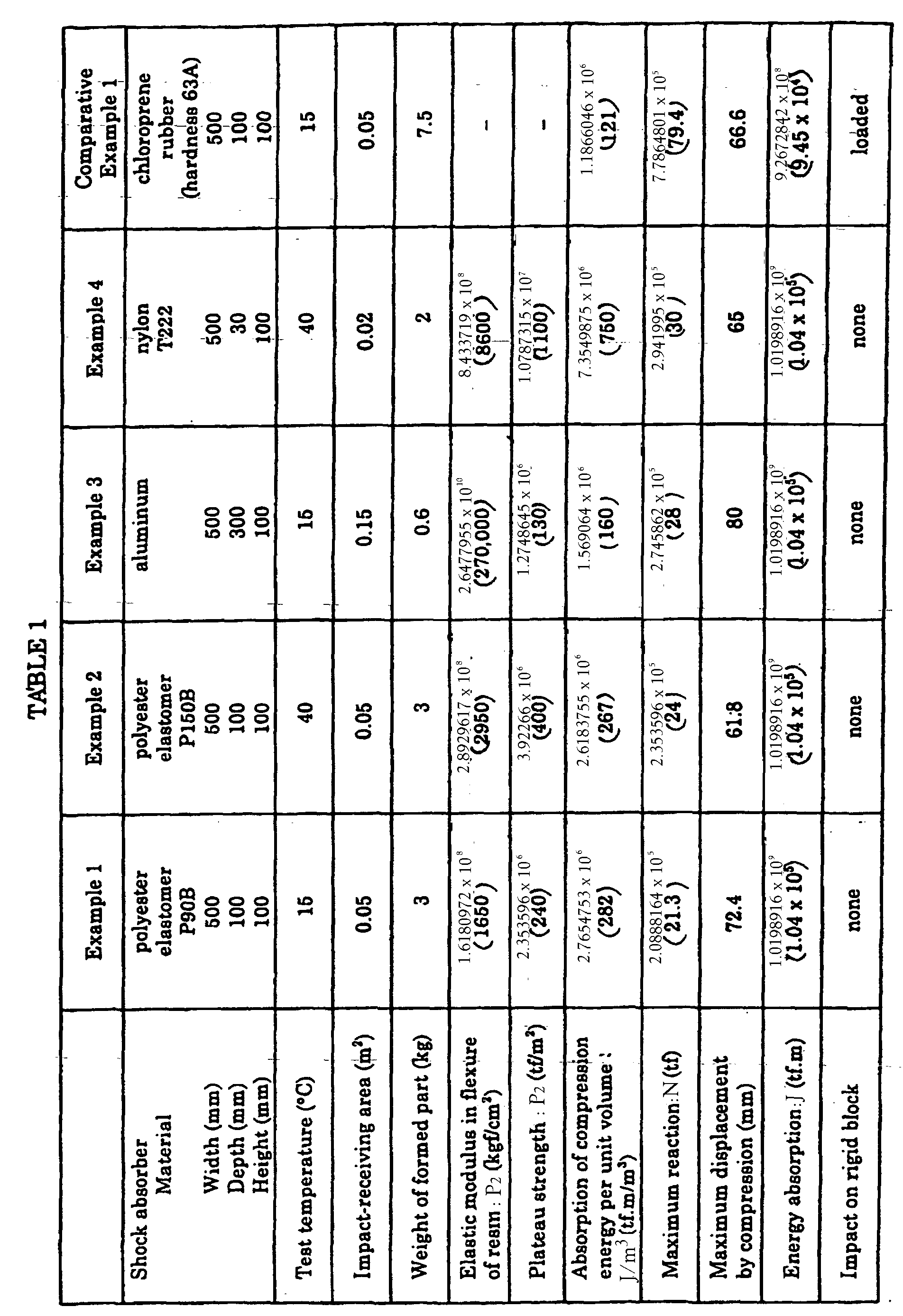
- A shock absorber with a double-flanged type cylindrical structure in the shape and size as shown in Figure 7 and in Table 2, respectively, was prepared by injection molding with polyester elastomer "PELPRENE® P-55B" available from Toyobo. The performance test of the shock absorber was performed at 15°C. The results are shown, together with the physical properties of the material, in Table 2.
- A shock absorber with a double-flanged type cylindrical structure in the shape and size as shown in Figure 7 and in Table 2, respectively, was prepared by injection molding with nylon "T222" available from Toyobo. The performance test of the shock absorber was performed at 40°C. The results are shown, together with the physical properties of the material, in Table 2.
- A commercially available chloroprene rubber block of hardness 45A was cut into a shock absorber with a double-flanged type cylindrical structure in the same shape and size as described in Example 3. The performance test of the shock absorber was conducted at 15°C. The results are shown in Table 2.
- A commercially available chloroprene rubber block of hardness 63A was cut into a shock absorber with a double-flanged type cylindrical structure in the same shape and size as described in Example 3. The performance test of the shock absorber was conducted at 15°C. The results are shown in Table 2.
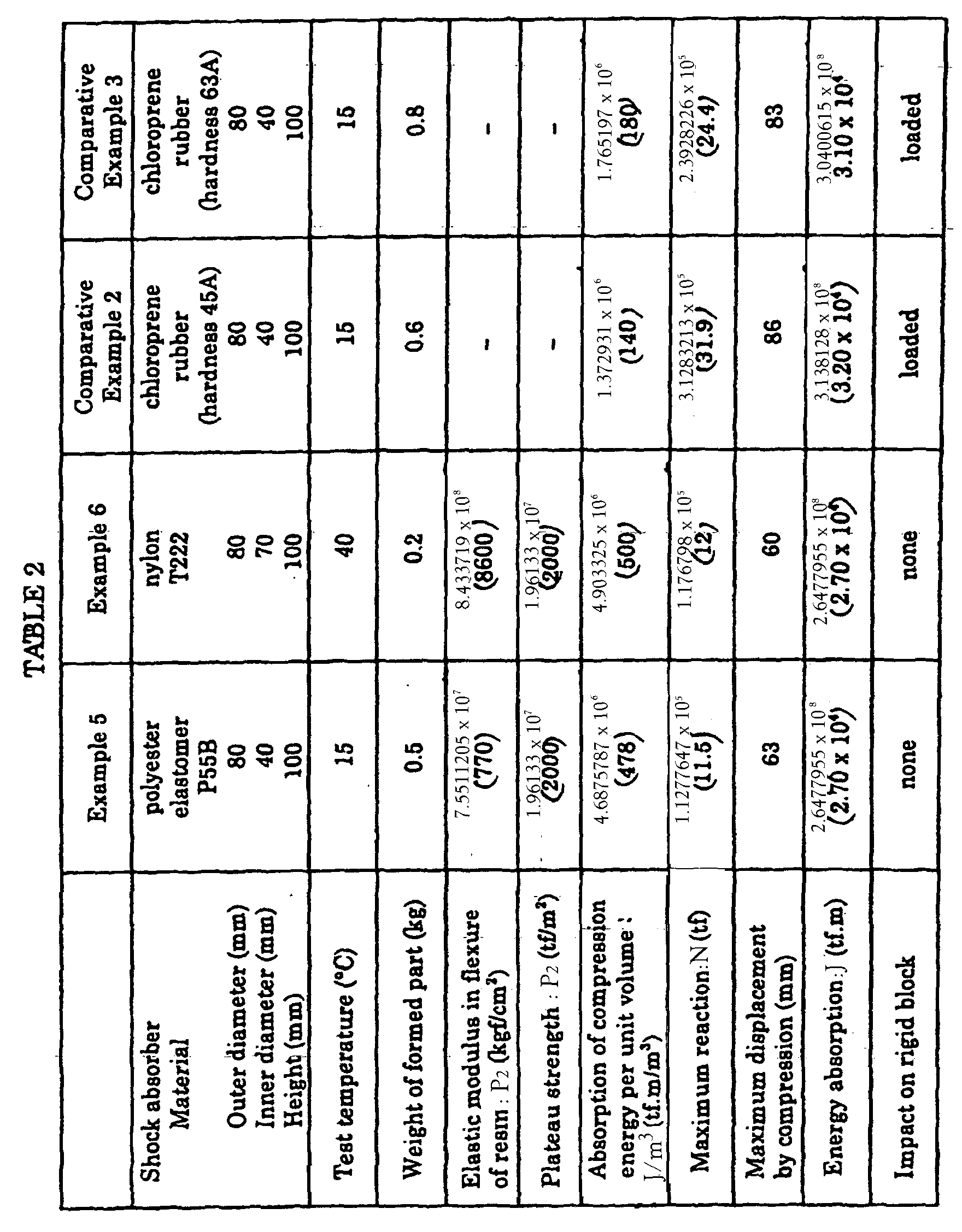
- As can be seen from Tables 1 and 2, the shock absorbers of Examples 1 to 6 exhibited excellent shock-absorbing performance, so that shock-absorbing construction with any of the shock absorbers can effectively absorb or attenuate the shock of collisions, by earthquakes or other factors, between the horizontal members or between the horizontal member and the vertical member, and the shock on the points of their connection through connectors. Therefore, the bridge of such shock-absorbing construction can prevent, with high reliability, the breakage or separation of horizontal members or vertical members, and the breakage of neighboring structures caused by these shocks, and can therefore sufficiently withstand to earthquakes or other factors. If the shock absorbers are formed from a material with excellent rust resistance, water resistance, and weatherability, the bridge containing such shock absorbers can find various applications, including inland bridges, coastal bridges, and marine connecting bridges, even in which case the bridge is free of maintenance to retain excellent shock-absorbing performance for a long period of time.
Claims (20)
- A bridge of shock-absorbing construction, comprising:wherein each of the plurality of shock absorbers (1) is formed from a material with an elastic modulus in flexure of 4.903325 x 10⁷ to 2.6477955 x 10¹⁰ Pa (500 to 270,000 kgf/cm2) and has a cell structure with a plurality of cells (2) separated by wall elements (3) having a length and a width, where the length is substantially greater than the width, characterized in that the plurality of shock absorbers (1) are arranged such that they do not regularly bear a load of the plurality of horizontal members (4), but they experience intentional buckling deformation or permanent deformation of the wall elements by compression when loaded substantially parallel to the lengthwise direction of the wall elements (3) with a shock generated by substantially horizontal movement of the plurality of horizontal members (4) during a seismic event, thereby attainin effective shock absorption, and each of the plurality of shock absorbers (1) has a plateau strength of 4.903325 x 10⁵ to 4.903325 x 10⁷ Pa (50 to 5,000 tf/m2) in the lengthwise direction of the wall elements (3).a plurality of horizontal members (4) arranged in series adjacent to one another;a plurality of vertical members (5) with bearing means (6) for supporting the plurality of horizontal members (4), anda plurality of shock absorbers (1) disposed at the points of possible contact between the plurality of horizontal members (4), or between at least one of the plurality of horizontal members (4), and one of the plurality of vertical members (5),
- The bridge according to claim 1, wherein each of the plurality of shock absorbers (1) absorbs compression energy of 4.903325 x 10⁵ J/m3 (50 tfm/m3) or higher when compressed in the lengthwise direction of the wall elements (3).
- The bridge according to claim 1, wherein each of the plurality of shock absorbers (1) is formed from a resin with an elastic modulus in flex e ranting form 4.903325 x 10⁴ to 1.96133 x 10⁹ Pa (500 to 20,000 kgf/cm2).
- The bridge according to claim 1, wherein each of the plurality of shock absorbents (1) is formed from a metal with an elastic modulus in flexure of 4.903325 x 10⁸ to 2.6477955 x 10¹⁰ Pa (5,000 to 270,000 kgf/cm2).
- The bridge according to claim 1, wherein at least one of the plurality of shock absorbers (1) has the wall elements (3) provided with a particular portion that first experiences intentional deformation when loaded with the shock.
- The bridge according to claim 5, wherein at least one of the plurality of shock absorbers (1) has the wall elements (3) with a cutout portion that first experiences intentional deformation when loaded with the shock.
- The bridge according to claim 5, wherein at least one of the plurality of shock absorbers (1) has the wall elements (3) with a stepped portion (7) that first experiences intentional deformation when loaded with the shock.
- The bridge according to claim 5, wherein at least one of the plurality of shock absorbers (1) has the wall elements (3) with a thin-walled portion that first experiences intentional deformation when loaded with the shock.
- The bridge according to claim 5, wherein the cell structure of at least one of the plurality of shock absorbers (1) has a hexagonal or lower polygonal pattern in a section perpendicular to the lengthwise direction of the wall elements (3).
- The bridge according to claim 9, wherein the cell structure of at least one of the plurality of shock absorbers (1) is a honeycomb structure with a hexagonal pattern in a section perpendicular to the lengthwise direction of the wall elements (3).
- A bridge of shock-absorbing construction, comprising:wherein each of the plurality of shock absorbers (21) is formed from a material with an elastic modulus in flexure of 1.96133 x 10⁷ to 8.433719 x 10⁸ Pa (200 to 8,600 kgf/cm2) and has a columnar structure with a column body having an axial hollow portion for passing the corresponding one of the plurality of connectors (22) therethrough, characterized in that the plurality of shock absorbers (21) are arranged such that they do not regularly bear a load of the plurality of horizontal members (26), but they experience intentional buckling deformation or permanent deformation of the column body by compression when loaded substantially parallel to the axial direction of the hollow portion with a shock generated by substantially horizontal movement of the plurality of horizontal members (26) during a seismic event, thereby attaining effective shock absorption, and each of the plurality of shock absorbers (21) has a plateau strength of 3.92266 x 10² to 1.96133 x 10⁸ Pa (400 to 20,000 tf/m2) in the axial direction of the hollow portion.a plurality of horizontal members (26) arranged in series adjacent to one another;a plurality of vertical members (28) with bearing means for supporting the plurality of horizontal members (26);a plurality of connectors (22) for connecting at least one of the plurality of adjacent horizontal members (26), one of the plurality of horizontal members (26), and one of the plurality of vertical members (29); anda plurality of shock absorbers (21) disposed at the ends of the plurality of connectors such that at least one of the plurality of connectors (22) runs through a corresponding at least one ofthe plurality of shock absorbers (21),
- The bridge according to claim 11, wherein each of the plurality of shock absorbers (21) absorbs compression energy of 1.96133 x 10⁶ to 4.903325 x 10⁶ J/m3 (200 to 500 tfm/m3) or higher when compressed in the axial direction of the hollow portion.
- The bridge according to claim 11, wherein each of the plurality of shock absorbers (21) is formed from a resin with an elastic modulus in flexure ranging from 1.96133 x 10⁷ to 4.903325 x 10⁸ Pa (200 to 5,000 kgf/cm2).
- The bridge according to claim 11, wherein each of the plurality of shock absorbers (21) is formed from a metal with an elastic modulus in flexure of 4.903325 x 10⁷ to 2.6477955 x 10¹⁰ Pa (5,000 to 270,000 kgf/cm2).
- The bridge according to claim 11, wherein at least one of the plurality of shock absorbers (21) has a flange.
- The bridge according to claim 11, wherein at least one of the plurality of shock absorbers (21) has the column body with a particular portion that first experiences intentional deformation when loaded with the shock.
- The bridge according to claim 16, wherein at least one of the plurality of shock absorbers (21) has the column body with a cutout portion that first experiences intentional deformation when loaded with the shock.
- The bridge according to claim 16, wherein at least one of the plurality of shock absorbers (21) has the column body with a thin-walled portion that first experiences intentional deformation when loaded with the shock.
- The bridge according to claim 16, wherein at least one of the plurality of shock absorbers (21) has the column body with an accordion portion that first experiences intentional deformation when loaded with the shock.
- The bridge according to claim 11, wherein at least one of the plurality of connectors (22) is a connection cable.
Applications Claiming Priority (6)
| Application Number | Priority Date | Filing Date | Title |
|---|---|---|---|
| JP17490897 | 1997-06-30 | ||
| JP17490797 | 1997-06-30 | ||
| JP174908/97 | 1997-06-30 | ||
| JP17490797 | 1997-06-30 | ||
| JP174907/97 | 1997-06-30 | ||
| JP17490897 | 1997-06-30 |
Publications (2)
| Publication Number | Publication Date |
|---|---|
| EP0889179A1 EP0889179A1 (en) | 1999-01-07 |
| EP0889179B1 true EP0889179B1 (en) | 2005-05-04 |
Family
ID=26496354
Family Applications (1)
| Application Number | Title | Priority Date | Filing Date |
|---|---|---|---|
| EP98111604A Expired - Lifetime EP0889179B1 (en) | 1997-06-30 | 1998-06-24 | Bridge of shock-absorbing construction |
Country Status (5)
| Country | Link |
|---|---|
| US (1) | US6249925B1 (en) |
| EP (1) | EP0889179B1 (en) |
| KR (1) | KR100591372B1 (en) |
| AT (1) | ATE294908T1 (en) |
| DE (1) | DE69830025D1 (en) |
Families Citing this family (13)
| Publication number | Priority date | Publication date | Assignee | Title |
|---|---|---|---|---|
| ES2169683B1 (en) * | 2000-09-22 | 2003-12-01 | Innovacion Y Diseno Orovay S L | MODULAR PROVISION OF PROTECTION ANTISEISMS APPLICABLE IN THE CONSTRUCTION OF BUILDINGS AND SIMILAR. |
| JP4454192B2 (en) * | 2001-08-07 | 2010-04-21 | Thk株式会社 | Rolling body interference prevention device of guide device |
| NZ524611A (en) | 2003-03-07 | 2005-09-30 | Robinson Seismic Ltd | Bearing assembly with sliding member between upper and lower bearing seats with elastic self-centering sleeve around seats |
| US20070223993A1 (en) * | 2006-03-23 | 2007-09-27 | Martin Marietta Materials, Inc. | Panel system connector |
| KR100723333B1 (en) | 2006-03-27 | 2007-06-04 | 이옥신 | New / replacement bridge device mount and its construction system installed on bridge |
| US8360404B2 (en) * | 2009-03-09 | 2013-01-29 | FYCM Enterprises, LLC | Shock absorbing interposer |
| US20110033655A1 (en) * | 2009-08-07 | 2011-02-10 | Duchene Rainer K | Energy saving honeycomb having enhanced strength |
| ITMI20121416A1 (en) * | 2012-08-08 | 2014-02-09 | Edilmatic S R L | ANTI-SEISMIC CONNECTION DEVICE FOR THE CONNECTION OF STRUCTURAL ELEMENTS |
| WO2018036519A1 (en) * | 2016-08-24 | 2018-03-01 | 中铁二院工程集团有限责任公司 | Method for improving anti-seismic performance of bridge by means of girder body, and energy-consumption and vibration-reduction bridge bearing |
| CN106677100A (en) * | 2017-03-24 | 2017-05-17 | 秦山伟业建设集团有限公司 | Green anti-collision guard railing and construction process thereof |
| CN112523068A (en) * | 2020-12-04 | 2021-03-19 | 北京城建道桥建设集团有限公司 | Mounting and fixing structure and construction method of inverted T-shaped bent cap damping chloroprene rubber sheet |
| CN116771002B (en) * | 2023-07-05 | 2026-01-02 | 西北核技术研究所 | A multi-purpose engineering structural protection structure |
| CN118517015B (en) * | 2024-07-23 | 2024-10-01 | 中铁上海工程局集团华南市政建设有限公司 | Assembled bridge anti-seismic foundation |
Family Cites Families (21)
| Publication number | Priority date | Publication date | Assignee | Title |
|---|---|---|---|---|
| GB1084064A (en) | 1900-01-01 | |||
| US194580A (en) * | 1877-08-28 | Improvement in spring-floors | ||
| US440938A (en) * | 1890-11-18 | Thoni | ||
| US2305487A (en) * | 1941-06-09 | 1942-12-15 | Bert K Naster | Lighting device |
| US3130819A (en) | 1962-11-09 | 1964-04-28 | Hexcel Products Inc | Energy absorber |
| US3906687A (en) * | 1973-10-09 | 1975-09-23 | Morris Schupack | Segmental precast concrete post-tensioned overpass bridges with cantilevered abutment |
| FR2288648A1 (en) * | 1974-03-05 | 1976-05-21 | Peugeot & Renault | ENERGY ABSORBING COMPOSITE BUMPER |
| US4252482A (en) * | 1978-10-26 | 1981-02-24 | Pullman Incorporated | Railway car counter-balanced tilting deck |
| CA1206981A (en) | 1983-01-17 | 1986-07-02 | Elastometal Limited | Deflection control device |
| US4666130A (en) * | 1984-03-15 | 1987-05-19 | Energy Absorption Systems, Inc. | Expanded cell crash cushion |
| JPS6112779A (en) | 1984-06-28 | 1986-01-21 | Sunstar Giken Kk | Sealing method of automotive body |
| US5054251A (en) * | 1986-07-24 | 1991-10-08 | Kemeny Zoltan A | Structural shock isolation system |
| US4901486A (en) * | 1987-03-06 | 1990-02-20 | Kajima Corporation | Elasto-plastic damper |
| US4959934A (en) * | 1988-01-27 | 1990-10-02 | Kajima Corporation | Elasto-plastic damper for use in structure |
| JP2858181B2 (en) * | 1991-01-21 | 1999-02-17 | 横浜ゴム株式会社 | Energy absorbing structure |
| JP3629718B2 (en) * | 1994-03-30 | 2005-03-16 | 東洋紡績株式会社 | Resin shock absorption block |
| KR960013914A (en) | 1994-10-04 | 1996-05-22 | 고오사이 아끼오 | Shock Absorbing Structure |
| GB2305487A (en) | 1995-09-15 | 1997-04-09 | Darchem Eng Ltd | An impact energy absorber having a low initiation load |
| IT1283693B1 (en) * | 1996-08-06 | 1998-04-23 | A L G A Applic Lavorazione Giu | ANTI-SEISMIC DEVICE FOR ENERGY SINK FOR PRODUCTS SUCH AS VIADUCTS AND SIMILAR |
| US5832678A (en) * | 1996-10-18 | 1998-11-10 | Balco/Metalines, Inc. | Seismic portal |
| US5775038A (en) * | 1996-12-20 | 1998-07-07 | J. Muller International | Fixed point seismic buffer system |
-
1998
- 1998-06-23 US US09/103,111 patent/US6249925B1/en not_active Expired - Lifetime
- 1998-06-24 DE DE69830025T patent/DE69830025D1/en not_active Expired - Lifetime
- 1998-06-24 AT AT98111604T patent/ATE294908T1/en not_active IP Right Cessation
- 1998-06-24 EP EP98111604A patent/EP0889179B1/en not_active Expired - Lifetime
- 1998-06-30 KR KR1019980025576A patent/KR100591372B1/en not_active Expired - Fee Related
Also Published As
| Publication number | Publication date |
|---|---|
| DE69830025D1 (en) | 2005-06-09 |
| ATE294908T1 (en) | 2005-05-15 |
| EP0889179A1 (en) | 1999-01-07 |
| US6249925B1 (en) | 2001-06-26 |
| KR100591372B1 (en) | 2006-10-24 |
| KR19990007484A (en) | 1999-01-25 |
Similar Documents
| Publication | Publication Date | Title |
|---|---|---|
| EP0889179B1 (en) | Bridge of shock-absorbing construction | |
| KR100384571B1 (en) | Resin shock absorber | |
| US5685665A (en) | Roadway barrier and method of installation | |
| US5201155A (en) | Seismic isolating bearing | |
| US5369925A (en) | Post protector | |
| KR100469534B1 (en) | Impact absolber made of resin | |
| CA2599514C (en) | Self-centering energy dissipative brace apparatus with tensioning elements | |
| US20080238142A1 (en) | Motor vehicle frame structure and crashbox therefor | |
| CN105926794A (en) | Assembly type soft steel damper optimized through equal-stress line | |
| US20060137292A1 (en) | Reinforcing structure for building and reinforcing member for the structure | |
| JP3808822B2 (en) | Shock absorber of bridge | |
| JP2003184032A5 (en) | ||
| JP3437089B2 (en) | Bridge shock absorbing structure | |
| JPH05295713A (en) | Impulse force absorbing device for drop stone preventive body | |
| CN220725442U (en) | Building steel structure with good damping effect | |
| JP4142472B2 (en) | Retaining wall protection structure | |
| US20140075857A1 (en) | Energy Absorbing System for Safeguarding Structures from Disruptive Forces | |
| KR100638240B1 (en) | Device | |
| KR102283043B1 (en) | Plate type damper to reduce residual deformation | |
| US11084672B2 (en) | Dock bumpers and/or vehicles bumpers | |
| KR20050043104A (en) | A polyurethane for a bridge support earthquake control bearing | |
| JPH09302621A (en) | Low noise type base isolation stacked rubber bearing | |
| KR100448486B1 (en) | Apparatus for supporting bridge structures | |
| JP2005331035A (en) | Vibration control device | |
| CN220685846U (en) | Pavement sound barrier structure |
Legal Events
| Date | Code | Title | Description |
|---|---|---|---|
| PUAI | Public reference made under article 153(3) epc to a published international application that has entered the european phase |
Free format text: ORIGINAL CODE: 0009012 |
|
| AK | Designated contracting states |
Kind code of ref document: A1 Designated state(s): AT BE CH CY DE DK ES FI FR GB GR IE IT LI LU MC NL PT SE |
|
| AX | Request for extension of the european patent |
Free format text: AL;LT;LV;MK;RO;SI |
|
| 17P | Request for examination filed |
Effective date: 19990615 |
|
| AKX | Designation fees paid |
Free format text: AT BE CH CY DE DK ES FI FR GB GR IE IT LI LU MC NL PT SE |
|
| 17Q | First examination report despatched |
Effective date: 20020614 |
|
| GRAP | Despatch of communication of intention to grant a patent |
Free format text: ORIGINAL CODE: EPIDOSNIGR1 |
|
| GRAS | Grant fee paid |
Free format text: ORIGINAL CODE: EPIDOSNIGR3 |
|
| RIN1 | Information on inventor provided before grant (corrected) |
Inventor name: NONOMURA, CHISATO,C/O TOYO BOSEKI K. K. Inventor name: NEGISHI, KIYOSHI,C/O TOYO BOSEKI K. K. Inventor name: ARAKI, YOSHIO,C/O TOYO BOSEKI KABUSHIKI KAISHA Inventor name: MATSUYAMA, YUJIRO,C/O TOYO BOSEKI KABUSHIKI K. Inventor name: KAMATA, SAKASHI,C/O TOYO BOSEKI KABUSHIKI KAISHA Inventor name: KANNO, TADASHI,C/O JAPAN HIGHWAY PUBLIC CORP. Inventor name: KUBOTA, KENJI,C/O JAPAN HIGHWAY PUBLIC CORP. Inventor name: KAMIHIGASHI, YASUSHI,C/O JAPAN HIGHWAY PUBL. CORP Inventor name: ISHIDA, HIROMU,C/O JAPAN HIGHWAY PUBLIC CORP. |
|
| GRAA | (expected) grant |
Free format text: ORIGINAL CODE: 0009210 |
|
| AK | Designated contracting states |
Kind code of ref document: B1 Designated state(s): AT BE CH CY DE DK ES FI FR GB GR IE IT LI LU MC NL PT SE |
|
| PG25 | Lapsed in a contracting state [announced via postgrant information from national office to epo] |
Ref country code: NL Free format text: LAPSE BECAUSE OF FAILURE TO SUBMIT A TRANSLATION OF THE DESCRIPTION OR TO PAY THE FEE WITHIN THE PRESCRIBED TIME-LIMIT Effective date: 20050504 Ref country code: LI Free format text: LAPSE BECAUSE OF FAILURE TO SUBMIT A TRANSLATION OF THE DESCRIPTION OR TO PAY THE FEE WITHIN THE PRESCRIBED TIME-LIMIT Effective date: 20050504 Ref country code: FI Free format text: LAPSE BECAUSE OF FAILURE TO SUBMIT A TRANSLATION OF THE DESCRIPTION OR TO PAY THE FEE WITHIN THE PRESCRIBED TIME-LIMIT Effective date: 20050504 Ref country code: CH Free format text: LAPSE BECAUSE OF FAILURE TO SUBMIT A TRANSLATION OF THE DESCRIPTION OR TO PAY THE FEE WITHIN THE PRESCRIBED TIME-LIMIT Effective date: 20050504 Ref country code: BE Free format text: LAPSE BECAUSE OF FAILURE TO SUBMIT A TRANSLATION OF THE DESCRIPTION OR TO PAY THE FEE WITHIN THE PRESCRIBED TIME-LIMIT Effective date: 20050504 Ref country code: AT Free format text: LAPSE BECAUSE OF FAILURE TO SUBMIT A TRANSLATION OF THE DESCRIPTION OR TO PAY THE FEE WITHIN THE PRESCRIBED TIME-LIMIT Effective date: 20050504 |
|
| REG | Reference to a national code |
Ref country code: GB Ref legal event code: FG4D |
|
| REG | Reference to a national code |
Ref country code: CH Ref legal event code: EP |
|
| REG | Reference to a national code |
Ref country code: IE Ref legal event code: FG4D |
|
| REF | Corresponds to: |
Ref document number: 69830025 Country of ref document: DE Date of ref document: 20050609 Kind code of ref document: P |
|
| REG | Reference to a national code |
Ref country code: GR Ref legal event code: EP Ref document number: 20050401443 Country of ref document: GR |
|
| PG25 | Lapsed in a contracting state [announced via postgrant information from national office to epo] |
Ref country code: LU Free format text: LAPSE BECAUSE OF NON-PAYMENT OF DUE FEES Effective date: 20050624 Ref country code: IE Free format text: LAPSE BECAUSE OF NON-PAYMENT OF DUE FEES Effective date: 20050624 Ref country code: CY Free format text: LAPSE BECAUSE OF FAILURE TO SUBMIT A TRANSLATION OF THE DESCRIPTION OR TO PAY THE FEE WITHIN THE PRESCRIBED TIME-LIMIT Effective date: 20050624 |
|
| PG25 | Lapsed in a contracting state [announced via postgrant information from national office to epo] |
Ref country code: MC Free format text: LAPSE BECAUSE OF NON-PAYMENT OF DUE FEES Effective date: 20050630 |
|
| PG25 | Lapsed in a contracting state [announced via postgrant information from national office to epo] |
Ref country code: SE Free format text: LAPSE BECAUSE OF FAILURE TO SUBMIT A TRANSLATION OF THE DESCRIPTION OR TO PAY THE FEE WITHIN THE PRESCRIBED TIME-LIMIT Effective date: 20050804 Ref country code: GB Free format text: LAPSE BECAUSE OF NON-PAYMENT OF DUE FEES Effective date: 20050804 Ref country code: DK Free format text: LAPSE BECAUSE OF FAILURE TO SUBMIT A TRANSLATION OF THE DESCRIPTION OR TO PAY THE FEE WITHIN THE PRESCRIBED TIME-LIMIT Effective date: 20050804 |
|
| PG25 | Lapsed in a contracting state [announced via postgrant information from national office to epo] |
Ref country code: DE Free format text: LAPSE BECAUSE OF FAILURE TO SUBMIT A TRANSLATION OF THE DESCRIPTION OR TO PAY THE FEE WITHIN THE PRESCRIBED TIME-LIMIT Effective date: 20050805 |
|
| PG25 | Lapsed in a contracting state [announced via postgrant information from national office to epo] |
Ref country code: ES Free format text: LAPSE BECAUSE OF FAILURE TO SUBMIT A TRANSLATION OF THE DESCRIPTION OR TO PAY THE FEE WITHIN THE PRESCRIBED TIME-LIMIT Effective date: 20050815 |
|
| PG25 | Lapsed in a contracting state [announced via postgrant information from national office to epo] |
Ref country code: PT Free format text: LAPSE BECAUSE OF FAILURE TO SUBMIT A TRANSLATION OF THE DESCRIPTION OR TO PAY THE FEE WITHIN THE PRESCRIBED TIME-LIMIT Effective date: 20051017 |
|
| NLV1 | Nl: lapsed or annulled due to failure to fulfill the requirements of art. 29p and 29m of the patents act | ||
| REG | Reference to a national code |
Ref country code: CH Ref legal event code: PL |
|
| PLBE | No opposition filed within time limit |
Free format text: ORIGINAL CODE: 0009261 |
|
| STAA | Information on the status of an ep patent application or granted ep patent |
Free format text: STATUS: NO OPPOSITION FILED WITHIN TIME LIMIT |
|
| REG | Reference to a national code |
Ref country code: IE Ref legal event code: MM4A |
|
| 26N | No opposition filed |
Effective date: 20060207 |
|
| GBPC | Gb: european patent ceased through non-payment of renewal fee |
Effective date: 20050804 |
|
| EN | Fr: translation not filed | ||
| PGFP | Annual fee paid to national office [announced via postgrant information from national office to epo] |
Ref country code: IT Payment date: 20080603 Year of fee payment: 11 |
|
| PG25 | Lapsed in a contracting state [announced via postgrant information from national office to epo] |
Ref country code: FR Free format text: LAPSE BECAUSE OF NON-PAYMENT OF DUE FEES Effective date: 20050630 |
|
| PG25 | Lapsed in a contracting state [announced via postgrant information from national office to epo] |
Ref country code: FR Free format text: LAPSE BECAUSE OF NON-PAYMENT OF DUE FEES Effective date: 20050504 |
|
| PGFP | Annual fee paid to national office [announced via postgrant information from national office to epo] |
Ref country code: GR Payment date: 20080430 Year of fee payment: 11 |
|
| PG25 | Lapsed in a contracting state [announced via postgrant information from national office to epo] |
Ref country code: GR Free format text: LAPSE BECAUSE OF NON-PAYMENT OF DUE FEES Effective date: 20100107 |
|
| PG25 | Lapsed in a contracting state [announced via postgrant information from national office to epo] |
Ref country code: IT Free format text: LAPSE BECAUSE OF NON-PAYMENT OF DUE FEES Effective date: 20090624 |