EP0888795B1 - Pediatric programmable hydrocephalus valve - Google Patents
Pediatric programmable hydrocephalus valve Download PDFInfo
- Publication number
- EP0888795B1 EP0888795B1 EP98305249A EP98305249A EP0888795B1 EP 0888795 B1 EP0888795 B1 EP 0888795B1 EP 98305249 A EP98305249 A EP 98305249A EP 98305249 A EP98305249 A EP 98305249A EP 0888795 B1 EP0888795 B1 EP 0888795B1
- Authority
- EP
- European Patent Office
- Prior art keywords
- housing
- shunt valve
- valve
- width
- shunt
- Prior art date
- Legal status (The legal status is an assumption and is not a legal conclusion. Google has not performed a legal analysis and makes no representation as to the accuracy of the status listed.)
- Expired - Lifetime
Links
- 208000003906 hydrocephalus Diseases 0.000 title description 4
- 230000000087 stabilizing effect Effects 0.000 claims description 49
- 239000012530 fluid Substances 0.000 claims description 37
- 210000003625 skull Anatomy 0.000 claims description 13
- 239000000463 material Substances 0.000 claims description 10
- 230000001105 regulatory effect Effects 0.000 claims description 3
- 210000001175 cerebrospinal fluid Anatomy 0.000 description 16
- 210000004761 scalp Anatomy 0.000 description 13
- 229920001296 polysiloxane Polymers 0.000 description 9
- 238000002347 injection Methods 0.000 description 7
- 239000007924 injection Substances 0.000 description 7
- 238000005086 pumping Methods 0.000 description 7
- 239000000853 adhesive Substances 0.000 description 5
- 230000001070 adhesive effect Effects 0.000 description 5
- 230000002861 ventricular Effects 0.000 description 5
- 210000004556 brain Anatomy 0.000 description 4
- 238000002513 implantation Methods 0.000 description 4
- 238000007917 intracranial administration Methods 0.000 description 4
- -1 polyethylenes Polymers 0.000 description 3
- 229910001069 Ti alloy Inorganic materials 0.000 description 2
- RTAQQCXQSZGOHL-UHFFFAOYSA-N Titanium Chemical compound [Ti] RTAQQCXQSZGOHL-UHFFFAOYSA-N 0.000 description 2
- 210000005013 brain tissue Anatomy 0.000 description 2
- 238000004891 communication Methods 0.000 description 2
- 230000006835 compression Effects 0.000 description 2
- 238000007906 compression Methods 0.000 description 2
- 230000001276 controlling effect Effects 0.000 description 2
- 230000007423 decrease Effects 0.000 description 2
- 238000005096 rolling process Methods 0.000 description 2
- 239000010935 stainless steel Substances 0.000 description 2
- 238000001356 surgical procedure Methods 0.000 description 2
- 229910052719 titanium Inorganic materials 0.000 description 2
- 239000010936 titanium Substances 0.000 description 2
- 239000004698 Polyethylene Substances 0.000 description 1
- 239000004743 Polypropylene Substances 0.000 description 1
- 208000002667 Subdural Hematoma Diseases 0.000 description 1
- 238000005452 bending Methods 0.000 description 1
- 239000000560 biocompatible material Substances 0.000 description 1
- 230000017531 blood circulation Effects 0.000 description 1
- 210000004289 cerebral ventricle Anatomy 0.000 description 1
- 238000013461 design Methods 0.000 description 1
- 239000003814 drug Substances 0.000 description 1
- 229940079593 drug Drugs 0.000 description 1
- 230000000694 effects Effects 0.000 description 1
- 230000003028 elevating effect Effects 0.000 description 1
- 238000005516 engineering process Methods 0.000 description 1
- 210000003128 head Anatomy 0.000 description 1
- 230000001771 impaired effect Effects 0.000 description 1
- 238000003780 insertion Methods 0.000 description 1
- 230000037431 insertion Effects 0.000 description 1
- 201000009941 intracranial hypertension Diseases 0.000 description 1
- 230000000670 limiting effect Effects 0.000 description 1
- 239000007788 liquid Substances 0.000 description 1
- 230000007774 longterm Effects 0.000 description 1
- 229920002529 medical grade silicone Polymers 0.000 description 1
- 229910052751 metal Inorganic materials 0.000 description 1
- 239000002184 metal Substances 0.000 description 1
- 150000002739 metals Chemical class 0.000 description 1
- 238000000034 method Methods 0.000 description 1
- 238000012986 modification Methods 0.000 description 1
- 230000004048 modification Effects 0.000 description 1
- 230000035515 penetration Effects 0.000 description 1
- 210000003200 peritoneal cavity Anatomy 0.000 description 1
- 229920000573 polyethylene Polymers 0.000 description 1
- 229920000642 polymer Polymers 0.000 description 1
- 229920001155 polypropylene Polymers 0.000 description 1
- 229920002635 polyurethane Polymers 0.000 description 1
- 239000004814 polyurethane Substances 0.000 description 1
- 238000003825 pressing Methods 0.000 description 1
- 238000009877 rendering Methods 0.000 description 1
- 210000005245 right atrium Anatomy 0.000 description 1
- 238000007789 sealing Methods 0.000 description 1
- 239000013464 silicone adhesive Substances 0.000 description 1
- 229910001220 stainless steel Inorganic materials 0.000 description 1
- 229910001256 stainless steel alloy Inorganic materials 0.000 description 1
- 238000006467 substitution reaction Methods 0.000 description 1
- 238000001029 thermal curing Methods 0.000 description 1
Images




Classifications
-
- A—HUMAN NECESSITIES
- A61—MEDICAL OR VETERINARY SCIENCE; HYGIENE
- A61M—DEVICES FOR INTRODUCING MEDIA INTO, OR ONTO, THE BODY; DEVICES FOR TRANSDUCING BODY MEDIA OR FOR TAKING MEDIA FROM THE BODY; DEVICES FOR PRODUCING OR ENDING SLEEP OR STUPOR
- A61M27/00—Drainage appliance for wounds or the like, i.e. wound drains, implanted drains
- A61M27/002—Implant devices for drainage of body fluids from one part of the body to another
- A61M27/006—Cerebrospinal drainage; Accessories therefor, e.g. valves
Definitions
- Catheters of various types are used to drain fluid from different areas of the body of a patient.
- One application of such catheters is for the treatment of hydrocephalus, a condition where cerebrospinal fluid (CSF) collects in the ventricles of the brain of a patient.
- CSF cerebrospinal fluid
- the volume of CSF increases thereby elevating the intracranial pressure. This excess CSF can result in abnormally high epidural and intradural pressures.
- hydrocephalus can result in serious medical conditions, including subdural hematoma, compression of the brain tissue and impaired blood flow.
- fluid shunt systems include a valve mechanism for controlling or regulating the flow rate of fluid through the system.
- An illustrative shunt system includes a valve mechanism in fluid communication with a brain ventricular catheter. The ventricular catheter is inserted into a ventricle of the brain and a peritoneal catheter is inserted into the peritoneal region for discharge of the fluid.
- Exemplary shunt systems include U.S. Patent Nos. 4,332,255, 4,387,715, 4,551,128, and 3,886,948.
- FIG. 1 shows a prior art shunt system 10 having a ventricular catheter 12 inserted through a hole 14 in the skull 15 of a patient.
- the catheter 12 is advanced through brain tissue 16, and into a ventricle 18 of the brain where excess CSF is present.
- the catheter 12 is coupled to an inlet end of a shunt valve 20 and a drainage catheter 22 is coupled to an outlet end of the shunt valve.
- the shunt valve 20 is typically implanted under the scalp (not shown) of the patient
- the shunt system is operative to drain excess CSF from the ventricle to another part of the body, such as the right atrium, peritoneal cavity, or other locations in the body.
- Shunt systems typically permit fluid flow only when the fluid pressure reaches a threshold pressure for the shunt valve.
- the fluid flow rate is proportional to the pressure at the valve mechanism.
- the flow rate is relatively low.
- the pressure increases the flow rate through the shunt system concomitantly increases.
- a maximum flow rate for the system is reached. Fluid flow normally continues until the intracranial pressure has been reduced to a level less than the threshold pressure, subject to any hysteresis of the device.
- the threshold pressure that allows fluid flow through a shunt system must often be adjusted. For example, a surgeon may initially select a relatively low threshold pressure to trigger fluid flow. Over time, the initial threshold pressure may not be ideal. For example, it could lead to excess fluid flow, creating an undesirable overdrainage condition in which too much fluid is drained from the ventricle. Such a situation may give rise to a need to increase the threshold pressure to afford a fluid flow rate that is balanced to avoid both excessive intracranial pressure and overdrainage conditions.
- the hydrocephalus shunt system is surgically implanted, and adjustment of the threshold pressure often requires the system to be surgically removed, adjusted, and then surgically implanted again. If the valve is not adjusted correctly, or if the intracranial pressure of the patient changes over time, then the valve must be readjusted, i.e., surgically removed and re-implanted.
- U.S. Patent Nos. 4,615,691 and 4,772,257 disclose a cerebrospinal fluid shunt valve that is externally adjustable by means of a programming device.
- the shunt valve includes a stepping motor having rotor and stator elements.
- the stator elements are composed of a magnetically soft and permeable material shaped and positioned with respect to the rotor.
- the external programming device applies a magnetic field causing the rotor to rotate about a central axis so as to adjust the threshold pressure.
- the programming device includes a surface having a groove therein for accommodating a protrusion on the scalp of a patient caused by the implanted shunt valve.
- the device includes a plurality of generally coplanar electromagnets disposed about a central axis.
- the programming device is first placed against the head of the patient so that the scalp protrusion is within the groove of the device.
- An operator verifies the longitudinal position of the shunt valve within the groove to enable proper pressure adjustment.
- the central axis of the electromagnets and rotor should be substantially coaxial to ensure accurate programming of the valve. Once the proper position is achieved, the electromagnets in the programming device are energized to apply a magnetic field to actuate the stepper motor and select a predetermined threshold pressure for the valve mechanism.
- Misalignment can occur due to rotation of the shunt valve under the patient's scalp.
- the external programmer must be placed adjacent to the top surface of the shunt system. Any rotation or rolling of the system will misalign the system, making external adjustment difficult or impossible.
- the shunt valve is typically disposed in a generally rectangular housing with rounded corners.
- the valve has an aspect ratio with respect to height and width that is approximately unity, making it somewhat prone to rolling.
- the valve can also be housed within a generally circular silicone housing that further contributes to a rounding of the valve, creating further rotational instability.
- the shunt valve and stepper motor rotor can easily displace from a programmable position where the rotor axis is normal to a portion of the skull where the valve is located. Under certain conditions, such as a well placed impact, the valve can rotate forty-five degrees or more, thus rendering the programming device useless and requiring surgical removal of the valve in order to effect pressure adjustment.
- the present invention provides a surgically implantable shunt system according to claim 1 that is useful to drain fluid from one part of a patient's body to another.
- the device is a shunt system implantable within the cranium for draining excess cerebrospinal fluid (CSF).
- CSF cerebrospinal fluid
- the device is primarily described and illustrated as a CSF shunt valve, it is understood that it can be used for other types of implantable valve systems as well.
- the programming device allows a user to adjust the threshold pressure of the valve above which fluid flows through the device to allow drainage of CSF through the shunt system.
- the relative position of the programming device with respect to the valve element must be such that the programming device can apply the magnetic field at an orientation that actuates the stepper motor.
- the shunt valve system of the invention further includes a stabilizing member that is either integral with or attached to the bottom portion of the housing.
- the stabilizing member has a substantially flat bottom surface adapted for placement on, or proximate, the skull of a patient.
- the flat bottom surface of the stabilizing member extends beyond the width of the housing to increase rotational stability and to prevent rotation of the device with respect to the skull.
- the stabilizing member helps to prevent rotation of the shunt valve with respect to the skull, thus ensuring that the external programming device can effectively adjust the threshold pressure of the shunt valve without surgical removal.
- FIGS. 2A-D show a prior art externally programmable shunt valve system 50 and an external programming device 52 for adjusting a threshold pressure at which fluid begins to flow through the device.
- the shunt valve 50 is typically surgically implanted under the scalp of a patient.
- the programming device 52 includes a control device 54 for selecting a threshold pressure and a programming element 56 that is placed over the scalp protrusion that is created by the implanted shunt valve.
- the shunt valve 50 includes a stepper motor 58 that is actuated by a magnetic field applied by the programming element 56 to adjust the threshold pressure of the shunt valve.
- the shunt valve 50 includes a valve body 60 defining a chamber 62 with an inlet opening 64 and an outlet opening 66. When a fluid pressure at the inlet opening exceeds the predetermined threshold, fluid begins to flow through the shunt valve via the inlet and outlet openings 64,66.
- a support plate 68 is disposed within the valve body 60 and includes an aperture 70 at one end that is provided with a valve seat 72.
- a ball 74 is adapted for sealing engagement with the valve seat 72.
- a first end 76 of a spring 78 biases the ball to the valve seat 72 to prevent fluid flow.
- the biasing force of the spring 78 is adjustable by varying the vertical position of the spring at a second end 80, which can be adjusted by means of a cam 82.
- the cam 82 includes a plurality of steps of varying vertical position with respect to the plate 68. Each step provides a discrete pressure on the ball 74 via the spring 78. The biasing force provided by the spring 78 determines the threshold pressure that must be overcome in order to separate the ball from the valve seat and allow fluid flow into the chamber 62.
- the cam 82 is disposed in a centrally located hole in a rotor 84 which includes a plurality of permanent magnetic poles of alternate polarity. At any one angular position, a pole exposed on the top side has an opposite pole on the other side.
- a stator member 86 Below the rotor 84, four stator elements are fixed in a stator member 86.
- the stator elements are formed from a magnetically soft and permeable material.
- the stator elements are shaped to conform to the rotor 84 elements.
- the threshold pressure can be adjusted by using the programmer 52.
- the programming element 56 of the programmer includes a housing 90 having a groove 92 adapted to conform to a protrusion on the scalp caused by the implanted shunt valve. An operator maneuvers the programming element 56 so that the scalp protrusion is within the groove 92. Thereafter, a series of electromagnets 94 disposed about a central axis are sequentially energized to apply a pulsed magnetic field to the stepper motor and cause the rotor to rotate. This causes the cam 82 to rotate and therefore adjust the pressure applied to the ball 74 by the first end 76 of the spring. In this manner, the threshold pressure of the shunt valve is adjusted.
- the central axis of the electromagnets is coaxial with the axis defined by rotation of the rotor 84. Exact alignment of theses axes is not necessary and the programmer is tolerant of some misalignment. However, as the degree of misalignment increases, the accuracy and reliability of the programmer decreases. Further, if the implanted shunt valve rotates a significant amount about its longitudinal axis x, such as more than about forty-five degrees, the shunt valve can no longer be programmed.
- the valve 50 has a valve body 60 with a generally rectangular cross section, rounded corners and a non-planar bottom surface 96 that is adapted for placement against the scalp.
- This shape facilitates insertion of the shunt valve 50 into a generally circular silicone housing 98.
- the geometry of the valve body 60 is somewhat unstable and the shunt valve is prone to rotation about its longitudinal axis x. Rotation of the shunt valve can occur spontaneously, or it can be caused by an impact or a force applied to the shunt valve. This tendency toward rotation can be further compounded by the generally circular silicone housing 98 surrounding the shunt valve which contributes to the rounding of the corners of the valve body.
- FIG. 3 illustrates a shunt valve 100 in accordance with the present invention.
- the shunt valve 100 includes a housing or valve body 102 and a separate, substantially flat stabilizing member 104 bonded to the valve body.
- the valve body 102 defines an outlet aperture 108 and an inlet aperture 110.
- An element for regulating fluid flow through the shunt valve, such as valve 106, is disposed within the valve body 102 for controlling the flow rate of fluid through the device.
- the valve 106 is an adjustable valve mechanism including a stepper motor 112 having a fixed stator and a rotor for turning cam 114 to adjust the vertical height of spring 116 and thereby adjust the threshold pressure that biases ball 118 into valve seat 120.
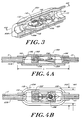
- FIGS. 4A-C show further details of the shunt valve 100.
- the housing or valve body 102 includes a top surface 102a and sidewalls 102b that define a first width W1.
- the shunt valve 100 has a length L with respect to a longitudinal axis X of the shunt valve.
- the stabilizing member 104 has a thickness T and includes a bottom surface 124 that has a second width W2 that is substantially greater than the width W1 of the housing 102.
- the stabilizing member 104 laterally extends beyond the valve body to decrease the height/width aspect ratio of the shunt valve.
- This design possesses inherent rotational stability, making the shunt valve 100 more reliable and more easily and accurately externally programmable.
- the valve body 102 may have a width W1 that ranges from 5 ⁇ 08-25 ⁇ 4 mm (0.20 to 1.00 inch). More preferably the W1 dimension is about 6 ⁇ 35 mm (0.25 inch).
- the width (W2) of the stabilizing member 104 is 2 ⁇ 54 - 10 ⁇ 16 mm (0.10 to 0.40 inch) greater than the W1 dimension.
- the stabilizing member 104 has a width (W2) that is about 2 ⁇ 54-5 ⁇ 08 mm (0.10 to 0.20 inch) greater than W1.
- the stabilizing member preferably extends beyond the sidewalls 102b of the housing 102 by about 1 ⁇ 397-1 ⁇ 524 mm (0.055 to 0.060 inch).
- the dimensions of the housing 102 can vary and that such variations in the housing dimensions will influence the width of the stabilizing member 104.
- the height/width aspect ratio of the valve 100 should be maintained in the range of about .20 to .35 to achieve the desired rotational stability.
- the stabilizing member 104 is a separate element that is bonded to the bottom 102c of housing 102.
- the stabilizing member 104 can be bonded with a suitable adhesive that is biocompatible and compatible with the valve body and stabilizing member.
- the adhesive must be permanent and strong, yet allow the stabilizing member to flex to the match the skull contour.
- exemplary adhesives include silicone adhesives such as Dow-Corning medical adhesive "A" or similar materials. Bonding may also be effected by other techniques, such as compression and thermal curing of uncured silicone.
- FIG. 4D is an alternative embodiment to the shunt valve of FIGS. 4A-C that includes a housing 102' having a bottom surface 102c spanning the length of the housing and extending from one sidewall 102b of the housing to the other sidewall.
- the bottom surface 102c of the housing can be adhesively bonded to the stabilizing member 104 as described above.
- the bottom surface 102c has a thickness T1 that can range from about 0 ⁇ 508-1 ⁇ 016 mm (.020 to .040 inch) and preferably is about 0 ⁇ 762 mm (.030 inch).
- the length of the shunt valve is in the range from 12 ⁇ 7-22 ⁇ 86 mm (0.5 inch to 0.9 inches). In an exemplary embodiment, the length L of the valve body is 22 ⁇ 86 mm (0.90 inch).
- the thickness T of the stabilizing member can vary depending upon the requirements of a given application.
- the thickness T affects the rigidity of the shunt valve 100.
- the thickness should not be so great as to prevent the stabilizing member from conforming to the curvature of a patient's skull.
- the thickness T is in the range of about 0 ⁇ 381-1 ⁇ 016 mm (.015 to .040 inch), and more preferably is about 0 ⁇ 508 mm (.020 inch).
- the stabilizing member 104 and the valve body 102 can be made from a variety of biocompatible materials suitable for long term and/or permanent implantation within the body. Although not necessary, these components can be made of the same material. Suitable materials preferably are semi-rigid, allowing the stabilizing member to conform to the curvature of the skull. However, the material should not be so flexible as to allow an amount of bending of the stabilizing member 104 in an axis transverse to longitudinal axis X. Exemplary materials include polymers, such as polyurethane, silicones, polyethylenes, polypropylenes, and metals such as titanium, titanium alloys and stainless steel. A preferred material is medical grade silicone made by Dow-Corning or Nusil Silicone Technology.
- housing 102 is shown having a rounded top surface and opposed side walls, one of ordinary skill in the art will appreciate that other profiles are possible as well.
- the housing can define a semicircular, triangular, or other such symmetrical or non-symmetrical cross sections.
- the low height/width aspect ratio of the shunt valve 100 resists rotation of the device about the longitudinal axis X.
- the width of the stabilizing member 104 impedes rotation of the shunt valve and the shunt valve is able to remain on the skull of the patient in the preferred orientation.
- a surgeon or another medical professional can ascertain the relative position of the shunt valve 100 through tactile examination of the scalp protrusion caused by the shunt valve. Such an examination is helpful to verify that the stabilizing member 104 remains against the skull of patient and that the valve has not rotated to any significant extent.
- the mechanism can also be oriented by x-ray to determine if the valve has rotated. A typically correct position of the valve is provided for comparison to the latest x-ray.
- FIGS 4A-B show the shunt valve having an adhesive seal band 125. The seal prevents flow around the valve mechanism in either direction within the silicone housing.
- the shunt valve 100 can be coupled to tubing at the inlet aperture 110 and outlet aperture 108 to accommodate fluid flow from one body location to another.
- an inlet tube 109 is coupled to the inlet aperture 110 to divert CSF from the ventricular catheter to the shunt valve.
- An outlet tube 111 is coupled to the outlet aperture 108 to provide a CSF discharge conduit from the shunt valve to another location in the body.
- the entire shunt valve is inserted into a generally circular silicone housing.
- the shunt valve occludes the tube such that any fluid flow through the tubing must pass through the valve 100 via inlet aperture 110 and outlet aperture 108.
- FIGS. 5-5C show a further embodiment of a fluid shunt valve 200 in accordance with the present invention.
- the shunt valve 200 includes a valve housing 202 having a stabilizing portion 204 with a substantially flat bottom stabilizing surface 206.
- the stabilizing portion 204 is integrally formed with the valve housing 202.
- a valve mechanism 208 is disposed within the valve housing 202 and establishes a threshold pressure necessary to initiate fluid flow through the shunt valve.
- the valve mechanism 208 may be of a type, as discussed above, that includes a stepper motor 210 that is actuable by an externally applied magnetic field to adjust the threshold pressure.
- the valve housing 202 includes the stabilizing portion 204 that is integrally joined to upper housing 212.
- Upper housing 212 includes a top wall 202a and opposed side walls 202b.
- the upper portion 212 has a width W1 that is less than a width W2 of the stabilizing portion 204.
- the W2 dimension range 2 ⁇ 54 - 10 ⁇ 16 mm from (0.10 to 0.40 inch) greater than W1, and preferably from 1 ⁇ 524-5 ⁇ 08 mm (0.10 to 0.20 inch) greater than W1.
- the upper portion 212 is centrally disposed on stabilizing portion 204.
- the width of the upper portion 212 and/or stabilizing portion 204 can be substantially constant over the length of the shunt valve, or this dimension may be variable.
- the length of the shunt valve 200 ranges from 12 ⁇ 7 mm (0.50 inch) to 22 ⁇ 86 mm (0 ⁇ 90 inches).
- the stabilizing portion 204 of the shunt valve has a thickness T that can vary from about 0 ⁇ 508-1 ⁇ 016 mm (0.02 to 0.04 inch). In an exemplary embodiment, the shunt valve length is about 17.78 mm (0.70 inch) and the thickness T of the stabilizing portion 204 is about 0.762 mm (0.03 inch).
- FIGS. 6 and 6A illustrate another embodiment of a shunt valve assembly 300 having a valve mechanism 302 and a pumping chamber 304 for pumping fluid downstream of the shunt valve.
- the pumping chamber 304 is actuated by applying pressure to a flexible portion 306 of the assembly that is disposed above the pumping chamber 304.
- the pumping chamber 304 is disposed adjacent an outlet opening 308 of the valve mechanism 302.
- the shunt valve assembly includes a housing 310 in which the valve mechanism 302 and/or pumping chamber 304 are disposed.
- Assembly 300 further includes a substantially flat stabilizing member 312.
- the stabilizing member 312 can be a separate member that is bonded to the housing 310 or it can be integrally formed with the housing.
- the stabilizing member 312 has the properties described above with respect to stabilizing member 104 and 204. That is, stabilizing member 312 is substantially wider than the valve housing 310 so that it can prevent rotation of the assembly after implantation of the assembly under the scalp of a patient.
- the stabilizing member 312 has a width that is greater than a width of the valve housing 310 by an amount that ranges from about 2 ⁇ 54-5 ⁇ 08 mm (0.10 to 0.20 inch).
- FIGS. 7 and 7A show a shunt valve assembly 400 having an injection area 402 with an impenetrable needle stop 404 for maintaining a needle within the injection area.
- the injection area 402 is disposed in fluid communication with an inlet opening 406 of the assembly.
- a syringe can be inserted through the scalp and then through a wall 408 of the injection area 402 to inject drugs or other liquids into the injection area.
- the injection area 402 also provides a source from which a fluid sample can be withdrawn.
- the needle stop 404 is effective to prevent the syringe from passing out of the injection area and through the bottom of the assembly.
- the needle stop 404 is formed from titanium, stainless steel, or titanium alloys, or other suitable material that is biocompatible and penetration resistant.
- the shunt valve assembly 400 includes a housing 410 and a substantially flat stabilizing member 412 integral with the housing or separately bonded thereto as described above.
- a valve mechanism 414 is disposed within the housing 410.
- the valve 414 provides a threshold pressure above which fluid is permitted to flow through the device.
- the valve mechanism 414 includes a stepper motor actuated by an externally applied magnetic field.
- the shunt valve assembly 400 can optionally include a pumping chamber 416 disposed at an outlet opening 418 of the assembly, as described above with respect to Figures 6 and 6A.
- the properties and dimensions of the stabilizing member 412 are as described above with respect to Figures 3-6A. It is understood that the width of the stabilizing member must sufficiently exceed that of the housing 410 to prevent rotation of the assembly 400 after implantation.
Landscapes
- Health & Medical Sciences (AREA)
- Engineering & Computer Science (AREA)
- Biomedical Technology (AREA)
- Hematology (AREA)
- Ophthalmology & Optometry (AREA)
- Otolaryngology (AREA)
- Anesthesiology (AREA)
- Heart & Thoracic Surgery (AREA)
- Neurology (AREA)
- Life Sciences & Earth Sciences (AREA)
- Animal Behavior & Ethology (AREA)
- General Health & Medical Sciences (AREA)
- Public Health (AREA)
- Veterinary Medicine (AREA)
- External Artificial Organs (AREA)
- Prostheses (AREA)
Applications Claiming Priority (2)
| Application Number | Priority Date | Filing Date | Title |
|---|---|---|---|
| US887045 | 1997-07-02 | ||
| US08/887,045 US5928182A (en) | 1997-07-02 | 1997-07-02 | Pediatric programmable hydrocephalus valve |
Publications (2)
| Publication Number | Publication Date |
|---|---|
| EP0888795A1 EP0888795A1 (en) | 1999-01-07 |
| EP0888795B1 true EP0888795B1 (en) | 2002-10-09 |
Family
ID=25390340
Family Applications (1)
| Application Number | Title | Priority Date | Filing Date |
|---|---|---|---|
| EP98305249A Expired - Lifetime EP0888795B1 (en) | 1997-07-02 | 1998-07-01 | Pediatric programmable hydrocephalus valve |
Country Status (5)
| Country | Link |
|---|---|
| US (1) | US5928182A (es) |
| EP (1) | EP0888795B1 (es) |
| JP (1) | JP4233636B2 (es) |
| DE (1) | DE69808558T2 (es) |
| ES (1) | ES2185114T3 (es) |
Families Citing this family (136)
| Publication number | Priority date | Publication date | Assignee | Title |
|---|---|---|---|---|
| US5637083A (en) * | 1996-01-19 | 1997-06-10 | Pudenz-Schulte Medical Research Corporation | Implantable adjustable fluid flow control valve |
| US20060057573A1 (en) * | 2002-02-15 | 2006-03-16 | Somalogic, Inc | Methods and reagents for detecting target binding by nucleic acid ligands |
| US6090062A (en) * | 1998-05-29 | 2000-07-18 | Wayne State University | Programmable antisiphon shunt system |
| US6977140B1 (en) * | 1998-09-29 | 2005-12-20 | Organ Recovery Systems, Inc. | Method for maintaining and/or restoring viability of organs |
| US6673594B1 (en) | 1998-09-29 | 2004-01-06 | Organ Recovery Systems | Apparatus and method for maintaining and/or restoring viability of organs |
| US7749693B2 (en) * | 1998-09-29 | 2010-07-06 | Lifeline Scientific, Inc. | Method of determining that an organ is not suitable for transplantation and using it for testing substances |
| DE60024437T2 (de) * | 1999-03-17 | 2006-07-13 | Medtronic, Inc., Minneapolis | Werkzeug zum einstellen eines implantierbaren und einstellbaren durchflussregelventils |
| US6684904B2 (en) * | 1999-06-15 | 2004-02-03 | Seiko Instruments Inc. | Variable pressure valve apparatus |
| JP2000356275A (ja) * | 1999-06-15 | 2000-12-26 | Seiko Instruments Inc | 可変圧力弁装置 |
| JP2001104470A (ja) * | 1999-10-04 | 2001-04-17 | Seiko Instruments Inc | 弁装置及びこれを用いた弁システム |
| JP2001104471A (ja) * | 1999-10-04 | 2001-04-17 | Seiko Instruments Inc | 圧力可変弁装置及び該弁装置の設定圧力検出装置 |
| JP3852734B2 (ja) * | 1999-12-20 | 2006-12-06 | セイコーインスツル株式会社 | 圧力可変弁装置及び該弁装置の設定圧力調整装置 |
| US6551280B1 (en) | 2000-06-30 | 2003-04-22 | Embro Corporation | Therapeutic device and system |
| JP3816873B2 (ja) * | 2000-12-11 | 2006-08-30 | クリストフ ミートケ ゲゼルシャフト ミット ベシュレンクテル ハフツング ウント コンパニー コマンディトゲゼルシャフト | 水頭症用バルブ |
| US6702249B2 (en) * | 2001-03-19 | 2004-03-09 | Seiko Instruments Inc. | Pressure-variable valve device and set-pressure adjusting device for the valve device |
| DE10113823A1 (de) * | 2001-03-21 | 2002-09-26 | Seiko Instr Inc | Druckregelventilvorrichtung und Vorrichtung zur Solldruckeinstellung des Ventils |
| US7025739B2 (en) * | 2001-08-09 | 2006-04-11 | Integra Lifesciences Corporation | System and method for treating elevated intracranial pressure |
| WO2003057015A2 (en) * | 2002-01-04 | 2003-07-17 | Kuchta, John | Csf physiologic controller |
| US8364229B2 (en) | 2003-07-25 | 2013-01-29 | Dexcom, Inc. | Analyte sensors having a signal-to-noise ratio substantially unaffected by non-constant noise |
| US7613491B2 (en) | 2002-05-22 | 2009-11-03 | Dexcom, Inc. | Silicone based membranes for use in implantable glucose sensors |
| US9694166B2 (en) | 2002-03-26 | 2017-07-04 | Medtronics Ps Medical, Inc. | Method of draining cerebrospinal fluid |
| US20040102761A1 (en) * | 2002-11-27 | 2004-05-27 | Ahmed A. Mateen | Portable pressure relief system & methods |
| JP4594862B2 (ja) * | 2002-12-11 | 2010-12-08 | クリストフ ミートケ ゲゼルシャフト ミット ベシュレンクテル ハフツング ウント コンパニー コマンディトゲゼルシャフト | 調節式水頭症バルブ |
| US7998114B2 (en) * | 2003-01-06 | 2011-08-16 | Maquet Cardiovascular Llc | Method and apparatus for regulating pressure during medical procedures |
| US7582068B2 (en) * | 2003-02-18 | 2009-09-01 | Medtronic, Inc. | Occlusion resistant hydrocephalic shunt |
| US7235060B2 (en) * | 2003-03-27 | 2007-06-26 | Codman & Shurtleff, Inc. | Hydrocephalus shunt system with endoscopic placement features |
| WO2004089085A2 (en) * | 2003-04-04 | 2004-10-21 | Organ Recovery Systems, Inc. | Device for separating gas from a liquid path |
| WO2004089235A2 (en) * | 2003-04-04 | 2004-10-21 | Organ Recovery Systems, Inc. | Methods and apparatus for perfusion, diagnosis, storage and/or transport of an organ or tissue |
| US7192413B2 (en) | 2003-06-11 | 2007-03-20 | Codman & Shurtleff, Inc. | Needle guard having inherent probe directing features |
| US8353857B2 (en) * | 2003-06-23 | 2013-01-15 | Codman & Shurtleff, Inc. | Implantable medical device having pressure sensors for diagnosing the performance of an implanted medical device |
| US7318813B2 (en) * | 2003-06-26 | 2008-01-15 | Codman & Shurtleff, Inc. | Self adjusting hydrocephalus valve |
| US9763609B2 (en) | 2003-07-25 | 2017-09-19 | Dexcom, Inc. | Analyte sensors having a signal-to-noise ratio substantially unaffected by non-constant noise |
| US8626257B2 (en) | 2003-08-01 | 2014-01-07 | Dexcom, Inc. | Analyte sensor |
| US7591801B2 (en) | 2004-02-26 | 2009-09-22 | Dexcom, Inc. | Integrated delivery device for continuous glucose sensor |
| US8886273B2 (en) | 2003-08-01 | 2014-11-11 | Dexcom, Inc. | Analyte sensor |
| US20190357827A1 (en) | 2003-08-01 | 2019-11-28 | Dexcom, Inc. | Analyte sensor |
| US7920906B2 (en) | 2005-03-10 | 2011-04-05 | Dexcom, Inc. | System and methods for processing analyte sensor data for sensor calibration |
| US9247900B2 (en) | 2004-07-13 | 2016-02-02 | Dexcom, Inc. | Analyte sensor |
| US8364230B2 (en) | 2006-10-04 | 2013-01-29 | Dexcom, Inc. | Analyte sensor |
| US8425416B2 (en) | 2006-10-04 | 2013-04-23 | Dexcom, Inc. | Analyte sensor |
| US8774886B2 (en) | 2006-10-04 | 2014-07-08 | Dexcom, Inc. | Analyte sensor |
| US8423114B2 (en) | 2006-10-04 | 2013-04-16 | Dexcom, Inc. | Dual electrode system for a continuous analyte sensor |
| US11633133B2 (en) | 2003-12-05 | 2023-04-25 | Dexcom, Inc. | Dual electrode system for a continuous analyte sensor |
| US8425417B2 (en) | 2003-12-05 | 2013-04-23 | Dexcom, Inc. | Integrated device for continuous in vivo analyte detection and simultaneous control of an infusion device |
| US8364231B2 (en) | 2006-10-04 | 2013-01-29 | Dexcom, Inc. | Analyte sensor |
| US8287453B2 (en) | 2003-12-05 | 2012-10-16 | Dexcom, Inc. | Analyte sensor |
| US7744555B2 (en) * | 2004-02-06 | 2010-06-29 | Depuy Spine, Inc. | Implant having a photocatalytic unit |
| US8267883B2 (en) * | 2004-02-06 | 2012-09-18 | Depuy Spine, Inc. | Photocatalytic implant having a sensor |
| US8057422B2 (en) * | 2004-02-25 | 2011-11-15 | Wolf Ii Erich W | Transcutaneous telemetry of cerebrospinal fluid shunt programmable-valve pressure using near-infrared (NIR) light |
| WO2005082025A2 (en) * | 2004-02-25 | 2005-09-09 | Wolf Erich W | System for transcutaneous monitoring of intracranial pressure (icp) using near infrared (nir) telemetry |
| US8808228B2 (en) | 2004-02-26 | 2014-08-19 | Dexcom, Inc. | Integrated medicament delivery device for use with continuous analyte sensor |
| DK1613388T3 (da) * | 2004-03-27 | 2008-03-25 | Christoph Miethke Gmbh & Co Kg | Indstillelig hydrocephalus-ventil |
| US20060004317A1 (en) | 2004-06-30 | 2006-01-05 | Christophe Mauge | Hydrocephalus shunt |
| WO2006127694A2 (en) | 2004-07-13 | 2006-11-30 | Dexcom, Inc. | Analyte sensor |
| US7857760B2 (en) | 2004-07-13 | 2010-12-28 | Dexcom, Inc. | Analyte sensor |
| US7783333B2 (en) | 2004-07-13 | 2010-08-24 | Dexcom, Inc. | Transcutaneous medical device with variable stiffness |
| US8989833B2 (en) | 2004-07-13 | 2015-03-24 | Dexcom, Inc. | Transcutaneous analyte sensor |
| US7399742B2 (en) * | 2004-07-23 | 2008-07-15 | Depuy Spine, Inc. | Anti-osteolytic therapy involving adiponectin |
| US7217425B2 (en) * | 2004-07-23 | 2007-05-15 | Depuy Spine, Inc. | Autologous coatings for implants |
| US20060019869A1 (en) * | 2004-07-23 | 2006-01-26 | Thomas Dimauro M | Intradiscal anti-inflammatory therapy involving autologous adiponectin |
| US8715733B2 (en) * | 2004-07-23 | 2014-05-06 | DePuy Synthes Products, LLC | Enhanced adipose tissue |
| US7559912B2 (en) * | 2004-09-30 | 2009-07-14 | Codman & Shurtleff, Inc. | High pressure range hydrocephalus valve system |
| US20060089589A1 (en) * | 2004-10-21 | 2006-04-27 | Portnoy Harold D | Resistive shunt valve |
| US7585280B2 (en) | 2004-12-29 | 2009-09-08 | Codman & Shurtleff, Inc. | System and method for measuring the pressure of a fluid system within a patient |
| US7775966B2 (en) * | 2005-02-24 | 2010-08-17 | Ethicon Endo-Surgery, Inc. | Non-invasive pressure measurement in a fluid adjustable restrictive device |
| US7927270B2 (en) | 2005-02-24 | 2011-04-19 | Ethicon Endo-Surgery, Inc. | External mechanical pressure sensor for gastric band pressure measurements |
| US7699770B2 (en) * | 2005-02-24 | 2010-04-20 | Ethicon Endo-Surgery, Inc. | Device for non-invasive measurement of fluid pressure in an adjustable restriction device |
| US8016744B2 (en) | 2005-02-24 | 2011-09-13 | Ethicon Endo-Surgery, Inc. | External pressure-based gastric band adjustment system and method |
| US7775215B2 (en) * | 2005-02-24 | 2010-08-17 | Ethicon Endo-Surgery, Inc. | System and method for determining implanted device positioning and obtaining pressure data |
| US7658196B2 (en) * | 2005-02-24 | 2010-02-09 | Ethicon Endo-Surgery, Inc. | System and method for determining implanted device orientation |
| US8066629B2 (en) * | 2005-02-24 | 2011-11-29 | Ethicon Endo-Surgery, Inc. | Apparatus for adjustment and sensing of gastric band pressure |
| US10362947B2 (en) | 2005-03-15 | 2019-07-30 | Integra LifeSciences Switzerland Sarl | Pressure sensing devices |
| US7510533B2 (en) * | 2005-03-15 | 2009-03-31 | Codman & Shurtleff, Inc. | Pressure sensing valve |
| DE102005013720A1 (de) | 2005-03-22 | 2012-08-02 | Christoph Miethke Gmbh & Co Kg | Einstellbares Hydrocephalusventil |
| US7618391B2 (en) * | 2005-04-20 | 2009-11-17 | Children's Medical Center Corporation | Waveform sensing and regulating fluid flow valve |
| JP2008539965A (ja) * | 2005-05-10 | 2008-11-20 | ザ リージェンツ オブ ザ ユニバーシティ オブ カリフォルニア | 臨床移植のための自浄式カテーテル |
| US7334594B2 (en) * | 2005-06-29 | 2008-02-26 | Codman & Shurtleff, Inc. | Apparatus and method for adjusting a locking mechanism of a shunt valve |
| US20070038171A1 (en) * | 2005-07-25 | 2007-02-15 | Mayer Peter L | Shunt system |
| US20070078398A1 (en) | 2005-08-27 | 2007-04-05 | Dextradeur Alan J | Multi-branched anti-reflux valve |
| US8333728B2 (en) * | 2005-12-01 | 2012-12-18 | Medtronic, Inc. | Implantable cerebrospinal fluid flow device and method of controlling flow of cerebrospinal fluid |
| EP1979025B1 (en) * | 2006-01-31 | 2012-05-30 | Francis A. Kralick | Implantable micro-system for treatment of hydrocephalus |
| WO2007092875A2 (en) * | 2006-02-09 | 2007-08-16 | Pizzi Francis J | Dual channel shunt device and method for ventriculo-peritoneal shunting of bloody cerebrospinal fluid |
| US20070208293A1 (en) * | 2006-03-03 | 2007-09-06 | Habah Noshy Mansour | Methods and devices for noninvasive pressure measurment in ventricular shunts |
| US8870742B2 (en) | 2006-04-06 | 2014-10-28 | Ethicon Endo-Surgery, Inc. | GUI for an implantable restriction device and a data logger |
| US8152710B2 (en) | 2006-04-06 | 2012-04-10 | Ethicon Endo-Surgery, Inc. | Physiological parameter analysis for an implantable restriction device and a data logger |
| US8298142B2 (en) | 2006-10-04 | 2012-10-30 | Dexcom, Inc. | Analyte sensor |
| US8562528B2 (en) | 2006-10-04 | 2013-10-22 | Dexcom, Inc. | Analyte sensor |
| US8447376B2 (en) | 2006-10-04 | 2013-05-21 | Dexcom, Inc. | Analyte sensor |
| US8449464B2 (en) | 2006-10-04 | 2013-05-28 | Dexcom, Inc. | Analyte sensor |
| US8275438B2 (en) | 2006-10-04 | 2012-09-25 | Dexcom, Inc. | Analyte sensor |
| US8478377B2 (en) | 2006-10-04 | 2013-07-02 | Dexcom, Inc. | Analyte sensor |
| US20080281249A1 (en) * | 2006-10-30 | 2008-11-13 | Michael Gertner | Valves and Conduits for Vascular Access |
| US20200037874A1 (en) | 2007-05-18 | 2020-02-06 | Dexcom, Inc. | Analyte sensors having a signal-to-noise ratio substantially unaffected by non-constant noise |
| US20080306434A1 (en) | 2007-06-08 | 2008-12-11 | Dexcom, Inc. | Integrated medicament delivery device for use with continuous analyte sensor |
| US7827845B2 (en) * | 2007-06-18 | 2010-11-09 | Codman & Shurtleff, Inc. | Method and kit for maintaining a sterile environment during calibration of a medical device |
| US10702174B2 (en) | 2007-06-27 | 2020-07-07 | Integra Lifesciences Corporation | Medical monitor user interface |
| US8123714B2 (en) | 2007-06-29 | 2012-02-28 | Codman & Shurtleff, Inc. | Programmable shunt with electromechanical valve actuator |
| EP2227132B1 (en) | 2007-10-09 | 2023-03-08 | DexCom, Inc. | Integrated insulin delivery system with continuous glucose sensor |
| US7842004B2 (en) | 2007-10-31 | 2010-11-30 | Codman & Shurtleff, Inc. | Wireless pressure setting indicator |
| US8454524B2 (en) | 2007-10-31 | 2013-06-04 | DePuy Synthes Products, LLC | Wireless flow sensor |
| US8480612B2 (en) | 2007-10-31 | 2013-07-09 | DePuy Synthes Products, LLC | Wireless shunts with storage |
| US9204812B2 (en) * | 2007-10-31 | 2015-12-08 | DePuy Synthes Products, LLC | Wireless pressure sensing shunts |
| US8396528B2 (en) | 2008-03-25 | 2013-03-12 | Dexcom, Inc. | Analyte sensor |
| DE102008030942A1 (de) | 2008-07-02 | 2010-01-07 | Christoph Miethke Gmbh & Co Kg | Hirnwasserdrainagen |
| US8088091B2 (en) | 2009-03-09 | 2012-01-03 | New Jersey Institute Of Technology | No clog shunt using a compact fluid drag path |
| US8241240B2 (en) | 2009-11-09 | 2012-08-14 | Medtronic Xomed, Inc. | Adjustable valve setting with motor control |
| DE102009060533B4 (de) * | 2009-12-23 | 2019-07-11 | Christoph Miethke Gmbh & Co Kg | Implantierbares Shuntsystem |
| JP5511486B2 (ja) | 2010-04-26 | 2014-06-04 | 康雄 藍原 | 水頭症治療用シャントバルブ |
| US8322365B2 (en) | 2010-08-17 | 2012-12-04 | Codman & Shurtleff, Inc. | Implantable adjustable valve |
| US9149615B2 (en) | 2010-08-17 | 2015-10-06 | DePuy Synthes Products, Inc. | Method and tools for implanted device |
| DE102010051743B4 (de) | 2010-11-19 | 2022-09-01 | C. Miethke Gmbh & Co. Kg | Programmierbares Hydrocephalusventil |
| US8298168B2 (en) * | 2011-01-27 | 2012-10-30 | Medtronic Xomed, Inc. | Adjustment for hydrocephalus shunt valve |
| US9848809B2 (en) | 2011-04-15 | 2017-12-26 | Dexcom, Inc. | Advanced analyte sensor calibration and error detection |
| EP2717680A1 (en) | 2011-06-09 | 2014-04-16 | Lifeline Scientific, Inc. | Data record for organ transport and/or storage, comprising biomarker and events information |
| US10569065B2 (en) | 2012-09-11 | 2020-02-25 | Christoph Miethke Gmbh & Co Kg | Adjustable hydrocephalus valve |
| DE102012017886A1 (de) | 2012-09-11 | 2014-03-13 | C. Miethke Gmbh & Co. Kg | Einstellbares Hydrocephalus-Ventil |
| US9050436B2 (en) | 2013-03-14 | 2015-06-09 | DePuy Synthes Products, LLC | Adjustable resistance, gravitationally activated, anti-syphon valve |
| US9636070B2 (en) | 2013-03-14 | 2017-05-02 | DePuy Synthes Products, Inc. | Methods, systems, and devices for monitoring and displaying medical parameters for a patient |
| US10420337B2 (en) | 2013-03-15 | 2019-09-24 | Lifeline Scientific, Inc. | Transporter with a glucose sensor for determining viability of an organ or tissue |
| WO2014145858A2 (en) | 2013-03-15 | 2014-09-18 | Bitol Designs, Llc | Occlusion resistant catheter and method of use |
| EP2967381B1 (en) | 2013-03-15 | 2018-12-12 | Carlos A. Hakim | Shunt valve assembly |
| US20140278468A1 (en) | 2013-03-15 | 2014-09-18 | I.D. Therapeutics Llc | Apparatus and method for optimizing treatment using medication compliance patterns and glucose sensor |
| US9216275B2 (en) | 2013-09-30 | 2015-12-22 | DePuy Synthes Products, Inc. | Adjustable height hydrocephalus valve location device |
| US10226193B2 (en) | 2015-03-31 | 2019-03-12 | Medtronic Ps Medical, Inc. | Wireless pressure measurement and monitoring for shunts |
| WO2018031936A1 (en) * | 2016-08-12 | 2018-02-15 | Hakim Carlos | Externally programmable magnetic valve assembly and controller |
| US12420075B2 (en) | 2016-08-12 | 2025-09-23 | Ceredyn Biotechnology Llc | Externally programable magnetic valve assembly and controller |
| US11752315B1 (en) | 2016-10-07 | 2023-09-12 | Carlos A. Hakim | Method of treating normal pressure hydrocephalus |
| JP7000453B2 (ja) | 2017-04-06 | 2022-01-19 | クリストフ ミートケ ゲゼルシャフト ミット ベシュレンクテル ハフツング ウント コンパニー コマンディトゲゼルシャフト | 流量調整器 |
| DE102018000941A1 (de) | 2017-04-06 | 2018-11-22 | Christoph Miethke Gmbh & Co Kg | Implantierbares Hydrocephalusventil |
| US11439798B2 (en) | 2017-04-24 | 2022-09-13 | Longeviti Neuro Solutions Llc | Cerebral spinal fluid shunt plug |
| US11045632B2 (en) | 2017-04-24 | 2021-06-29 | Longeviti Neuro Solutions Llc | Cerebral spinal fluid shunt plug |
| US12569655B2 (en) * | 2017-04-24 | 2026-03-10 | Longeviti Neuro Solutions, Inc. | Cerebral spinal fluid shunt plug |
| US11331022B2 (en) | 2017-10-24 | 2022-05-17 | Dexcom, Inc. | Pre-connected analyte sensors |
| EP3928687B1 (en) | 2017-10-24 | 2024-06-26 | Dexcom, Inc. | Wearable device with pre-connected analyte sensor |
| US20210187257A1 (en) * | 2019-12-19 | 2021-06-24 | Neurovention Llc | Craniospinal surgical drain |
| CN120900103B (zh) * | 2025-09-30 | 2026-01-30 | 中国医学科学院北京协和医院 | 一种用于脑脊液分流装置的调压球阀及调压系统 |
Family Cites Families (42)
| Publication number | Priority date | Publication date | Assignee | Title |
|---|---|---|---|---|
| US3886948A (en) * | 1972-08-14 | 1975-06-03 | Hakim Co Ltd | Ventricular shunt having a variable pressure valve |
| US4281667A (en) * | 1976-06-21 | 1981-08-04 | Cosman Eric R | Single diaphragm telemetric differential pressure sensing system |
| US4653508A (en) * | 1976-06-21 | 1987-03-31 | Cosman Eric R | Pressure-balanced telemetric pressure sensing system and method therefore |
| US4281666A (en) * | 1976-06-21 | 1981-08-04 | Cosman Eric R | Single diaphragm pressure-balanced telemetric pressure sensing system |
| US4206762A (en) * | 1976-06-21 | 1980-06-10 | Cosman Eric R | Telemetric differential pressure sensing method |
| US4206761A (en) * | 1976-06-21 | 1980-06-10 | Cosman Eric R | Pressure-balanced telemetric pressure sensing method |
| US4660568A (en) * | 1976-06-21 | 1987-04-28 | Cosman Eric R | Telemetric differential pressure sensing system and method therefore |
| US4332255A (en) * | 1979-01-10 | 1982-06-01 | Hakim Company Limited | Shunt valve |
| US4387715A (en) * | 1980-09-23 | 1983-06-14 | Hakim Company Limited | Shunt valve |
| US4382445A (en) * | 1980-12-04 | 1983-05-10 | Cosmos Research Associates | Physiological fluid shunt system and improvements therefor |
| FR2502012A1 (fr) * | 1981-03-18 | 1982-09-24 | Sophysa Sa | Valve pour le traitement de l'hydrocephalie |
| US4741730A (en) * | 1982-10-04 | 1988-05-03 | American Hospital Supply | Hydrocephalus shunt with in-line filter |
| US4551128A (en) * | 1983-05-11 | 1985-11-05 | Salomon Hakim | Cerebrospinal fluid shunt valve |
| US4615691A (en) * | 1983-12-08 | 1986-10-07 | Salomon Hakim | Surgically-implantable stepping motor |
| US4595390A (en) * | 1983-07-21 | 1986-06-17 | Salomon Hakim | Magnetically-adjustable cerebrospinal fluid shunt valve |
| US4772257A (en) * | 1983-12-08 | 1988-09-20 | Salomon Hakim | External programmer for magnetically-adjustable cerebrospinal fluid shunt valve |
| US4787887A (en) * | 1984-08-16 | 1988-11-29 | Biomedica Mexicana, S.A. | Ventricular by-pass valve for draining the cephalorachidian liquid in the hydrocephalus |
| US4589287A (en) * | 1984-09-17 | 1986-05-20 | American Hospital Supply Corporation | Strain gauge for medical pressure measurements |
| US4781673A (en) * | 1985-12-20 | 1988-11-01 | Kabushiki Kaisha Nihon M.D.M. | Brain ventricle shunt system with flow-rate switching mechanism |
| US4676772A (en) * | 1985-12-23 | 1987-06-30 | Cordis Corporation | Adjustable implantable valve having non-invasive position indicator |
| US4673384A (en) * | 1986-04-14 | 1987-06-16 | Sophysa | Valve for the treatment of hydrocephalus |
| US4787886A (en) * | 1987-02-05 | 1988-11-29 | Cosman Eric R | Pressure sensor controlled valve |
| US5069663A (en) * | 1988-10-11 | 1991-12-03 | Cordis Corporation | Hydrocephalus valve |
| US5000731A (en) * | 1989-03-30 | 1991-03-19 | Tai-Ting Wong | Shunting device adopted in the intracranial shunting surgical operation for the treatment of hydrocephalus |
| IT1235504B (it) * | 1989-08-04 | 1992-09-05 | Istituto Di Fotografia Biomedi | Valvola a flusso variabile autoripulente preferibilmente per derivazioni ventricolari di liquor cefalorachidiano. |
| US5325865A (en) * | 1990-02-26 | 1994-07-05 | Baxter International, Inc. | Intracranial pressure monitoring system |
| US5154693A (en) * | 1990-05-15 | 1992-10-13 | Pudenz-Schulte Medical Research Corp. | Flow control device having selectable alternative fluid pathways |
| US5167615A (en) * | 1990-05-15 | 1992-12-01 | Pudenz-Schulte Medical Research Corporation | Flow control device having selectable alternative fluid pathways |
| US5176627A (en) * | 1990-05-15 | 1993-01-05 | Pudenz-Schulte Medical Research Corporation | Implantable fluid flow control device having two-piece base, and assembly process |
| US5304114A (en) * | 1991-05-15 | 1994-04-19 | Cosman Eric R | Shunt valve system |
| FR2685206B1 (fr) * | 1991-12-19 | 1998-03-06 | Cordis Sa | Dispositif de drainage implantable pour le traitement de l'hydrocephalie. |
| EP0617975B1 (fr) * | 1992-01-22 | 1997-08-20 | Cordis S.A. | Valve de drainage implantable pour le traitement de l'hydrocéphalie |
| US5207684A (en) * | 1992-04-13 | 1993-05-04 | Neuro Navigational Corporation | Sheath for shunt placement for hydrocephalus |
| US5257630A (en) * | 1992-05-15 | 1993-11-02 | Thermometrics, Inc. | Pressure sensing probe with calibration capability |
| FR2698535B1 (fr) * | 1992-11-30 | 1995-01-20 | Drevet Jean Baptiste | Dispositif de régulation et de contrôle de l'écoulement du liquide céphalo-rachidien dans un circuit de drainage. |
| EP0600413A3 (en) * | 1992-11-30 | 1995-04-05 | Neuro Navigational Corp | Neuroendoscope with shunt characteristic. |
| US5387188A (en) * | 1993-05-10 | 1995-02-07 | Pudenz-Schulte Medical Research Corporation | Pulsatile flow-accommodating fluid shunt |
| US5503320A (en) * | 1993-08-19 | 1996-04-02 | United States Surgical Corporation | Surgical apparatus with indicator |
| US5405316A (en) * | 1993-11-17 | 1995-04-11 | Magram; Gary | Cerebrospinal fluid shunt |
| FR2721520B1 (fr) * | 1994-06-24 | 1996-08-30 | Sophysa Sa | Valve sous-cutanée et son dispositif de réglage externe. |
| DE4427583C2 (de) * | 1994-08-04 | 1999-04-29 | Und Wilkau Reinhard Von Lieres | Shunt-Ventil für ein Drainagesystem zur Therapie des Hydrocephalus |
| US5637083A (en) * | 1996-01-19 | 1997-06-10 | Pudenz-Schulte Medical Research Corporation | Implantable adjustable fluid flow control valve |
-
1997
- 1997-07-02 US US08/887,045 patent/US5928182A/en not_active Expired - Lifetime
-
1998
- 1998-07-01 EP EP98305249A patent/EP0888795B1/en not_active Expired - Lifetime
- 1998-07-01 JP JP19947198A patent/JP4233636B2/ja not_active Expired - Lifetime
- 1998-07-01 DE DE69808558T patent/DE69808558T2/de not_active Expired - Lifetime
- 1998-07-01 ES ES98305249T patent/ES2185114T3/es not_active Expired - Lifetime
Also Published As
| Publication number | Publication date |
|---|---|
| DE69808558T2 (de) | 2003-06-26 |
| JPH11146911A (ja) | 1999-06-02 |
| DE69808558D1 (de) | 2002-11-14 |
| US5928182A (en) | 1999-07-27 |
| EP0888795A1 (en) | 1999-01-07 |
| ES2185114T3 (es) | 2003-04-16 |
| JP4233636B2 (ja) | 2009-03-04 |
Similar Documents
| Publication | Publication Date | Title |
|---|---|---|
| US5928182A (en) | Pediatric programmable hydrocephalus valve | |
| US8088092B2 (en) | High pressure range hydrocephalus valve system | |
| EP0552313B1 (en) | Check valve catheter | |
| EP1007140B1 (en) | Implantable adjustable fluid flow control valve | |
| US6090062A (en) | Programmable antisiphon shunt system | |
| US7771381B2 (en) | Shunt valve locking mechanism | |
| US7422566B2 (en) | Method of treating a patient with hydrocephalus and apparatus therefor | |
| JP4566595B2 (ja) | 患者から流体を排出するためのシャントシステム | |
| EP1486229B1 (en) | Needle guard having inherent probe directing features | |
| US10213585B2 (en) | Adjustable height hydrocephalus valve location device | |
| US7285296B2 (en) | Process for enriching extracts of natural theanine | |
| US20020026139A1 (en) | Valve seat and valve |
Legal Events
| Date | Code | Title | Description |
|---|---|---|---|
| PUAI | Public reference made under article 153(3) epc to a published international application that has entered the european phase |
Free format text: ORIGINAL CODE: 0009012 |
|
| AK | Designated contracting states |
Kind code of ref document: A1 Designated state(s): CH DE ES FR GB IT LI |
|
| AX | Request for extension of the european patent |
Free format text: AL;LT;LV;MK;RO;SI |
|
| RIN1 | Information on inventor provided before grant (corrected) |
Inventor name: PIKE, ROBERT W. Inventor name: PATEL, BHUPENDRA Inventor name: KRAUS, ROBERT G. |
|
| 17P | Request for examination filed |
Effective date: 19990617 |
|
| AKX | Designation fees paid |
Free format text: CH DE ES FR GB IT LI |
|
| 17Q | First examination report despatched |
Effective date: 20000724 |
|
| GRAG | Despatch of communication of intention to grant |
Free format text: ORIGINAL CODE: EPIDOS AGRA |
|
| GRAG | Despatch of communication of intention to grant |
Free format text: ORIGINAL CODE: EPIDOS AGRA |
|
| GRAH | Despatch of communication of intention to grant a patent |
Free format text: ORIGINAL CODE: EPIDOS IGRA |
|
| GRAH | Despatch of communication of intention to grant a patent |
Free format text: ORIGINAL CODE: EPIDOS IGRA |
|
| GRAA | (expected) grant |
Free format text: ORIGINAL CODE: 0009210 |
|
| AK | Designated contracting states |
Kind code of ref document: B1 Designated state(s): CH DE ES FR GB IT LI |
|
| REG | Reference to a national code |
Ref country code: GB Ref legal event code: FG4D |
|
| REG | Reference to a national code |
Ref country code: CH Ref legal event code: EP |
|
| REF | Corresponds to: |
Ref document number: 69808558 Country of ref document: DE Date of ref document: 20021114 |
|
| RAP2 | Party data changed (patent owner data changed or rights of a patent transferred) |
Owner name: DEPUY PRODUCTS, INC. |
|
| REG | Reference to a national code |
Ref country code: CH Ref legal event code: NV Representative=s name: E. BLUM & CO. PATENTANWAELTE |
|
| ET | Fr: translation filed | ||
| REG | Reference to a national code |
Ref country code: ES Ref legal event code: FG2A Ref document number: 2185114 Country of ref document: ES Kind code of ref document: T3 |
|
| RAP2 | Party data changed (patent owner data changed or rights of a patent transferred) |
Owner name: DEPUY PRODUCTS, INC. |
|
| PLBE | No opposition filed within time limit |
Free format text: ORIGINAL CODE: 0009261 |
|
| STAA | Information on the status of an ep patent application or granted ep patent |
Free format text: STATUS: NO OPPOSITION FILED WITHIN TIME LIMIT |
|
| 26N | No opposition filed |
Effective date: 20030710 |
|
| REG | Reference to a national code |
Ref country code: CH Ref legal event code: PFA Owner name: DEPUY PRODUCTS, INC. Free format text: DEPUY PRODUCTS, INC.#700 ORTHOPAEDIC DRIVE#WARSAW, INDIANA 46581 (US) -TRANSFER TO- DEPUY PRODUCTS, INC.#700 ORTHOPAEDIC DRIVE#WARSAW, INDIANA 46581 (US) |
|
| REG | Reference to a national code |
Ref country code: FR Ref legal event code: PLFP Year of fee payment: 19 |
|
| REG | Reference to a national code |
Ref country code: FR Ref legal event code: PLFP Year of fee payment: 20 |
|
| PGFP | Annual fee paid to national office [announced via postgrant information from national office to epo] |
Ref country code: CH Payment date: 20170627 Year of fee payment: 20 Ref country code: GB Payment date: 20170628 Year of fee payment: 20 Ref country code: FR Payment date: 20170613 Year of fee payment: 20 |
|
| PGFP | Annual fee paid to national office [announced via postgrant information from national office to epo] |
Ref country code: DE Payment date: 20170627 Year of fee payment: 20 Ref country code: IT Payment date: 20170720 Year of fee payment: 20 Ref country code: ES Payment date: 20170801 Year of fee payment: 20 |
|
| REG | Reference to a national code |
Ref country code: DE Ref legal event code: R071 Ref document number: 69808558 Country of ref document: DE |
|
| REG | Reference to a national code |
Ref country code: CH Ref legal event code: PL |
|
| REG | Reference to a national code |
Ref country code: GB Ref legal event code: PE20 Expiry date: 20180630 |
|
| PG25 | Lapsed in a contracting state [announced via postgrant information from national office to epo] |
Ref country code: GB Free format text: LAPSE BECAUSE OF EXPIRATION OF PROTECTION Effective date: 20180630 |
|
| REG | Reference to a national code |
Ref country code: ES Ref legal event code: FD2A Effective date: 20200723 |
|
| PG25 | Lapsed in a contracting state [announced via postgrant information from national office to epo] |
Ref country code: ES Free format text: LAPSE BECAUSE OF EXPIRATION OF PROTECTION Effective date: 20180702 |