EP0887652A2 - Measuring apparatus and method for measuring characteristic of solar cell - Google Patents
Measuring apparatus and method for measuring characteristic of solar cell Download PDFInfo
- Publication number
- EP0887652A2 EP0887652A2 EP98111624A EP98111624A EP0887652A2 EP 0887652 A2 EP0887652 A2 EP 0887652A2 EP 98111624 A EP98111624 A EP 98111624A EP 98111624 A EP98111624 A EP 98111624A EP 0887652 A2 EP0887652 A2 EP 0887652A2
- Authority
- EP
- European Patent Office
- Prior art keywords
- characteristic
- solar cell
- area
- measuring
- photo
- Prior art date
- Legal status (The legal status is an assumption and is not a legal conclusion. Google has not performed a legal analysis and makes no representation as to the accuracy of the status listed.)
- Ceased
Links
- 238000000034 method Methods 0.000 title claims description 72
- 238000004364 calculation method Methods 0.000 claims description 19
- 238000004519 manufacturing process Methods 0.000 claims description 15
- 230000008569 process Effects 0.000 claims description 14
- 238000012937 correction Methods 0.000 claims description 13
- 238000004590 computer program Methods 0.000 claims 4
- 238000005259 measurement Methods 0.000 description 21
- 238000002474 experimental method Methods 0.000 description 20
- 230000006870 function Effects 0.000 description 8
- 238000003860 storage Methods 0.000 description 6
- 238000010248 power generation Methods 0.000 description 5
- 229910052724 xenon Inorganic materials 0.000 description 3
- FHNFHKCVQCLJFQ-UHFFFAOYSA-N xenon atom Chemical compound [Xe] FHNFHKCVQCLJFQ-UHFFFAOYSA-N 0.000 description 3
- 238000007689 inspection Methods 0.000 description 2
- 238000012545 processing Methods 0.000 description 2
- 229910021417 amorphous silicon Inorganic materials 0.000 description 1
- 230000015572 biosynthetic process Effects 0.000 description 1
- 238000006243 chemical reaction Methods 0.000 description 1
- 238000011109 contamination Methods 0.000 description 1
- 230000006378 damage Effects 0.000 description 1
- 238000011161 development Methods 0.000 description 1
- 238000010586 diagram Methods 0.000 description 1
- 238000009826 distribution Methods 0.000 description 1
- 230000000694 effects Effects 0.000 description 1
- 230000007613 environmental effect Effects 0.000 description 1
- 238000011156 evaluation Methods 0.000 description 1
- 238000012986 modification Methods 0.000 description 1
- 230000004048 modification Effects 0.000 description 1
- 230000003287 optical effect Effects 0.000 description 1
- 230000002093 peripheral effect Effects 0.000 description 1
- 230000002285 radioactive effect Effects 0.000 description 1
- 238000001228 spectrum Methods 0.000 description 1
- 238000003892 spreading Methods 0.000 description 1
- 230000007480 spreading Effects 0.000 description 1
- 238000003786 synthesis reaction Methods 0.000 description 1
- 238000012360 testing method Methods 0.000 description 1
- 238000010792 warming Methods 0.000 description 1
Images


Classifications
-
- H—ELECTRICITY
- H02—GENERATION; CONVERSION OR DISTRIBUTION OF ELECTRIC POWER
- H02S—GENERATION OF ELECTRIC POWER BY CONVERSION OF INFRARED RADIATION, VISIBLE LIGHT OR ULTRAVIOLET LIGHT, e.g. USING PHOTOVOLTAIC [PV] MODULES
- H02S50/00—Monitoring or testing of PV systems, e.g. load balancing or fault identification
- H02S50/10—Testing of PV devices, e.g. of PV modules or single PV cells
-
- G—PHYSICS
- G01—MEASURING; TESTING
- G01R—MEASURING ELECTRIC VARIABLES; MEASURING MAGNETIC VARIABLES
- G01R19/00—Arrangements for measuring currents or voltages or for indicating presence or sign thereof
- G01R19/165—Indicating that current or voltage is either above or below a predetermined value or within or outside a predetermined range of values
-
- G—PHYSICS
- G01—MEASURING; TESTING
- G01R—MEASURING ELECTRIC VARIABLES; MEASURING MAGNETIC VARIABLES
- G01R31/00—Arrangements for testing electric properties; Arrangements for locating electric faults; Arrangements for electrical testing characterised by what is being tested not provided for elsewhere
- G01R31/40—Testing power supplies
-
- H—ELECTRICITY
- H10—SEMICONDUCTOR DEVICES; ELECTRIC SOLID-STATE DEVICES NOT OTHERWISE PROVIDED FOR
- H10F—INORGANIC SEMICONDUCTOR DEVICES SENSITIVE TO INFRARED RADIATION, LIGHT, ELECTROMAGNETIC RADIATION OF SHORTER WAVELENGTH OR CORPUSCULAR RADIATION
- H10F19/00—Integrated devices, or assemblies of multiple devices, comprising at least one photovoltaic cell covered by group H10F10/00, e.g. photovoltaic modules
- H10F19/90—Structures for connecting between photovoltaic cells, e.g. interconnections or insulating spacers
- H10F19/902—Structures for connecting between photovoltaic cells, e.g. interconnections or insulating spacers for series or parallel connection of photovoltaic cells
-
- Y—GENERAL TAGGING OF NEW TECHNOLOGICAL DEVELOPMENTS; GENERAL TAGGING OF CROSS-SECTIONAL TECHNOLOGIES SPANNING OVER SEVERAL SECTIONS OF THE IPC; TECHNICAL SUBJECTS COVERED BY FORMER USPC CROSS-REFERENCE ART COLLECTIONS [XRACs] AND DIGESTS
- Y02—TECHNOLOGIES OR APPLICATIONS FOR MITIGATION OR ADAPTATION AGAINST CLIMATE CHANGE
- Y02E—REDUCTION OF GREENHOUSE GAS [GHG] EMISSIONS, RELATED TO ENERGY GENERATION, TRANSMISSION OR DISTRIBUTION
- Y02E10/00—Energy generation through renewable energy sources
- Y02E10/50—Photovoltaic [PV] energy
Definitions
- the present invention relates to a measuring apparatus and method of measuring a characteristic of a solar cell and, more particularly, to a measuring apparatus and method of measuring a photoelectric conversion characteristic of a solar cell having a broader photo-sensing area than an illuminated area by a light source.
- Photovoltaic power generation has been collecting interests of many people as a clean power generation method which will meet an increasing demand for electric power and does not cause the destruction of the environment, since it does not cause environmental problems, such as radioactive contamination and anathermal of the earth, further, sunlight falls everywhere on the earth with some distribution inequality, and relatively large power generation efficiency is realized without a complicated and large facility. Accordingly, various studies and development are made on photovoltaic power generation to fit for
- a method of evaluating an output characteristic of a solar cell a method of studying a voltage vs. current characteristic (voltage/current characteristic) of a solar cell is generally used.
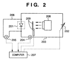
- Fig. 2 shows a configuration of an apparatus for evaluating the voltage/current characteristic.
- reference numeral 201 denotes a solar cell which is the object of evaluation; 202, a direct current (DC) power source; 203, Wires; 204, an ammeter; 205, a voltmeter; 206, wires used for measuring voltage; 207, a computer; 208, a light source; and 209, a shutter.
- DC direct current
- the DC power source 202 controlled by the computer 207, is connected to the solar cell 201 via the wire 203 and the ammeter 204.
- a bipolar DC power source is used as the DC power source 202; however, an electronic load may be used instead.
- the voltmeter 205 is connected across the solar cell 201.
- the values of current and voltage measured by the ammeter 204 and the voltmeter 205, respectively, are inputted to the computer 207.
- the light source 208 is warmed up and adjustment for emitting a standard quantity of light is performed.
- the light source 208 is on and the shutter 209 is closed.
- the solar cell 201 which is the object of the measurement, is set.
- the shutter 209 is opened and the entire surface of the solar cell 201 is illuminated with the standard light.
- the computer 207 controls the DC current source 202 to output a voltage.
- the voltage to be applied across the solar cell 201 depends upon the type of the solar cell 201, and the optimum voltage is predetermined for each type of a solar cell.
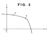
- the shutter 209 is closed, and the solar cell 201 is removed. Then, the voltage value data and the current value data stored in the memory of the computer 207 is graphed using a proper software, and a voltage/current characteristic curve as shown in Fig. 3 is obtained.
- Fig. 3 is a graph showing an example of voltage/current characteristic of the solar cell 201.
- V in the abscissa shows voltage
- I in the ordinate shows current.
- a curve C in Fig. 3 is obtained by connecting points representing the measured voltage values and current values plotted on the graph.
- a point K on the curve C is the point where the product of the voltage and the current becomes maximum, i.e., the point where maximum electric power is taken out, and generally called the optimum working point.
- the electric power taken out at the optimum working point is the rated power.
- Photovoltaic power generation has been rapidly spreading recently.
- a solar panel is often installed on the roof, for instance, and in an isolated island, a solar panel is often installed on a rack.
- a photo-sensing surface of each solar cell tends to be broadened.
- a light source capable of illuminating an area corresponding to the entire surface of the solar cell is necessary; however, it is very hard to obtain a light source of that kind.
- a Xenon lamp is most widely used as the light source, and a solar simulator using the Xenon lamp is used.
- the price of the solar simulator increases rapidly as the area that the Xenon lamp can illuminate increases. The increase in price is caused since it becomes harder to manufacture an air-mass filter and a condenser lens, both included in a solar simulator, as their sizes become larger, and the required output power from a power source for the lamp is extremely large.
- a practical fixed-light type solar simulator one having a light source capable of illuminating an area of about 50 cm by 50 cm is the largest on the current market.
- the solar simulator for measurement and test having a light source is expensive as described above; therefore, manufacturing cost of a solar cell increases. Accordingly, a method capable of measuring the characteristic of a solar cell having a broad surface at low cost is desired earnestly. Further, regarding a solar cell having a photo-sensing surface much greater than 1 m by 1 m, since a light source capable of illuminating such a broad area is not available, it is not possible, practically, to measure the characteristic of the solar cell.
- the present invention has been made in consideration of the above situation, and has as its object to provide a measuring apparatus and method of measuring a characteristic of a solar cell having a large photo-sensing surface at low cost.
- the foregoing object is obtained by providing a measuring method of measuring a characteristic of a solar cell comprising the steps of: measuring a first characteristic of the solar cell while illuminating a predetermined area of a photo-sensing surface of the solar cell, wherein an area of the photo-sensing surface which is not illuminated is called a dark area; measuring a second characteristic of the solar cell in a dark state in which the photo-sensing surface is shielded from light; calculating a third characteristic by multiplying the second characteristic by an area ratio of an area of the dark area to an area of the photo-sensing surface; and calculating a characteristic of the predetermined illuminated area on the basis of the first and third characteristics.
- the foregoing object is also attained by providing a measuring method of measuring a characteristic of a solar cell comprising the steps of: segmenting a photo-sensing surface of the solar cell into a plurality of blocks each having a predetermined area; measuring a first characteristic of the solar cell while illuminating each of the plurality of blocks, wherein an area of the photo-sensing surface which is not illuminated is called dark area; measuring a second characteristic of the solar cell in a dark state in which the photo-sensing surface is shielded from light; calculating a third characteristic by multiplying the second characteristic by an area ratio of an area of the dark area to an area of the photo-sensing surface; and calculating a characteristic of each of the plurality of the segmented block on the basis of the first and third characteristics of the corresponding block.
- the foregoing object is also attained by providing a manufacturing method of manufacturing a solar cell comprising a measuring step of measuring a characteristic of the solar cell in accordance with either of the above measuring methods.
- a measuring apparatus for measuring a characteristic of a solar cell comprising: a light source for illuminating a photo-sensing surface of the solar cell; and a mask, provided between the photo-sensing surface and the light source, for limiting an area to be illuminated on the photo-sensing surface to a predetermined area.
- Fig. 1 is a perspective view illustrating a configuration of an apparatus performing a measuring method according to the present invention.
- reference numeral 101 denotes a light source; 102, a mask; 103, a vertical movement unit; 104, a solar cell; 105, a sample holding stage; 106, wires; 110 and 111, driving units; and 112, a rack.
- the light source 101 has a function for illuminating the solar cell 104 with standard light for measurement, and has a shutter unit inside.
- the mask 102 is used for precisely determining the area to be illuminated on the solar cell 104. It is preferred to put rubber on the side, which touches the solar cell 104, of the mask 102 so that the solar cell 104 is not damaged. Further, the effective illuminated area by the light source 101 is adjusted slightly larger than an opening portion of the mask 102 but smaller than the outer size of the mask 102.
- the vertical movement unit 103 is used for moving the mask 102 downward for making the mask 102 contact with the solar cell 104, and upward before moving the light source 101 and the mask 102 in the horizontal direction.
- the solar cell 104 is set on the sample holding stage 105.
- the solar cell 104 may be fixed on the stage 105 by a clamp (not shown) to prevent the solar cell 104 from moving on the stage 105 during measuring of the characteristic.
- the solar cell 104 is connected to a power source for characteristic measurement (not shown), for instance, by the wires 106.
- a bipolar DC power source, a voltmeter and an ammeter which are used for measuring a characteristic, and wiring thereof are the same as those explained with reference to Fig. 2, therefore, the explanation of them are omitted.
- the driving unit 110 is used for moving the light source 101 and the mask 102 in the horizontal direction in Fig. 1 (X-direction), and the driving unit 111 is used for moving the light source 101 and the mask 102 in the depth direction in Fig. 1 (Y-direction).
- the rack 112 is used for installing the measuring apparatus comprising the light source 101, the mask 102, the vertical movement unit 103, the X-direction driving unit 110 and the Y-direction driving unit on a setting floor.
- the difference between the measuring apparatus shown in Fig. 1 and the measuring apparatus shown in Fig. 2 is that, in the latter one, the illuminated area by the light source 208 corresponds to the entire photo-sensing area of the solar cell 201, whereas, in the former one, the illuminated area by the light source 101 corresponds to a portion of the photo-sensing area of the solar cell 104.
- Fig. 12 is a flowchart showing the measurement sequence. The sequence shown in Fig. 12 is executed by an operator and/or the computer 207, which is shown in Fig. 2.
- Step S1 It is assumed that the apparatus is in a state that necessary warming up time has elapsed since the light source 101 is turned on, and a shutter (not shown) is closed. Further, ambient temperature is set to temperature suitable for measuring a characteristic of a solar cell. Specifically, the temperature is kept at about 25°C. Under these conditions, the solar cell 104 is set on the sample holding stage 105 and fixed by a clamp (not shown) when necessary. Thereafter, the wires 106 are connected to the solar cell 104.
- Step S2 The stage 105 holding the solar cell 104 and its peripheral area are completely shielded from light so that no light incidents on the solar cell 104, or shielded to the level in which the quantity of incidenting light is substantially ignorable with respect to 1sun. This state is called dark state.
- Step S3 Under the dark state of step S2, the voltage/current characteristic, explained with reference to Fig. 2, is measured, thereby obtaining the voltage/current characteristic of the solar cell 104 in the dark state (called "dark characteristic” hereinafter).
- the curve A shown in Fig. 4 shows a common measurement result of the dark characteristic. Note, the dark characteristic measured in this step is of the entire surface of the solar cell 104.
- Step S4 the voltage/current characteristic of the solar cell 104 is measured when it is illuminated.
- the photo-sensing surface of the solar cell 104 is divided into four blocks, and the measurement is performed individually for the respective four blocks.
- the number of blocks may be selected depending upon the size of the photo-sensing surface of the solar cell 104, an illuminated area by the light source 101, and the size of the opening of the mask 102.
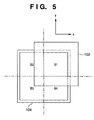
- Fig. 5 is an explanatory view for explaining an example when the photo-sensing surface of the solar cell 104 is divided or segmented into four blocks.
- B1 to B4 indicate the respective four blocks of the solar cell 104.
- the light source 101 is placed on top of the mask 102 with respect to Fig. 5, and faces to the solar cell 104 and the mask 102.
- Step S5 After the mask 102 is lifted up to a height where the mask 102 does not touch the solar cell 104 using the vertical movement unit 103, the mask 102 and the light source 101 are moved by the driving units 110 and 111 to positions where the block B1 is illuminated.
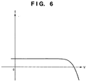
- Step S6 The vertical movement unit 103 moves the mask 102 down to a height where the backside of the mask 102 is contact with the solar cell 104. At this time, it is necessary to make the backside of the mask 102 contact with the solar cell 104 so that no space exists between the mask 102 and the solar cell 104. Under this condition, the shutter is opened, and the block B1 of the solar cell 104 is illuminated while keeping other blocks in the dark state, and a voltage/current characteristic of the solar cell 104 (referred to as "B1-bright, B2B3B4-dark characteristic" hereinafter) is measured. Fig. 6 shows the measurement result.
- Step S7 After measuring the B1-bright, B2B3B4-dark characteristic, the shutter is closed, thereby the illuminating of the block B1 is terminated.
- Step S8 Thereafter, the vertical moving unit 103 and the driving units 110 and 111 move the light source 101 and the mask 102 on the block B2, and measurement as performed in step S6 is performed. More specifically, the block B2 of the solar cell 104 is illuminated while keeping the rest of the blocks in the dark state, then a voltage/current characteristic (B2-bright, B1B3B4-dark characteristic) of the solar cell 104 is measured.
- a voltage/current characteristic B2-bright, B1B3B4-dark characteristic
- Step S9 Further, by repeating processes corresponding to steps S7 and S8, a B3-bright, B1B2B4-dark characteristic and a B4-bright, B1B2B3-dark characteristic of the solar cell 104 are measured.
- Step S10 After measuring the voltage/current characteristics for all the blocks, the shutter is closed, the mask 102 is lifted up, the wires 106 are disconnected from the solar cell 104, and the solar cell 104 is unloaded from the stage 105.
- Fig. 6 shows a graph of the measured voltage/current characteristics of the four blocks, namely, the B1-bright, B2B3B4-dark characteristic, the B2-bright, B1B3B4-dark characteristic, the B3-bright, B1B2B4-dark characteristic, and the B4-bright, B1B2B3-dark characteristic.
- the characteristic curves of the four measurement results coincide with each other in Fig. 6. This shows that characteristic of the solar cell 104 is the same over the photo-sensing surface. If the characteristic of the solar cell 104 is not similar enough over the photo-sensing surface, obtained four curves do not coincide perfectly.
- the characteristics obtained by illuminating the solar cell 104 by part in the foregoing operation are different from characteristics measured by each block when the blocks B1 to B4 are physically separated from each other.
- the reason is that the B1-bright, B2B3B4-dark characteristic, for example, is the sum of the characteristic of the block B1 when it is physically separated from the rest of the blocks and the dark characteristic of the other three blocks, namely, B2 to B4 blocks.
- the B1 block is electrically connected to the other three blocks of B2 to B4 in parallel as shown in the equivalent circuit diagram shown in Fig. 7.
- Fig. 7 the equivalent circuit diagram
- reference numeral 701 denotes the block B1 illuminated by light 710
- reference numeral 702 corresponds to the other three blocks of B2 to B4 in the dark state. Therefore, the characteristic of the solar cell 104 is the sum of a current value of the block B1 and current value of the other three blocks of B2 to B4.
- a curve B shown in Fig. 4, representing 3/4 of the current of the curve A for every voltage is obtained.
- the curve B represents the dark characteristic of three blocks, i.e., a dark area, which are not illuminated.
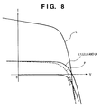
- a curve D in Fig. 8 corresponds to the curve B in Fig. 4, and a curve P in Fig. 8 corresponds to the curve of the B1-bright, B2B3B4-dark characteristic in Fig. 6.
- the B1-bright, B2B3B4-dark characteristic (curve P) is the sum of the characteristic measured in a state in which the block B1 is physically separated from the rest of the blocks (called "B1 bright characteristic” hereinafter) and the dark characteristic of the other three blocks (curve D). Therefore, the B1 bright characteristic is obtained by subtracting the dark characteristic of the three blocks from the B1-bright, B2B3B4-dark characteristic.
- a curve L1 in Fig. 8 shows the B1 bright characteristic obtained by performing the foregoing operation.
- the method of calculating the B1 bright characteristic is applied to the rest of the three blocks of B2 to B4 to obtain a B2 bright characteristic, a B3 bright characteristic, and a B4 bright characteristic.
- Curves L2 to L4 in Fig. 8 corresponds to these three bright characteristics.
- the curves L1 to L4 should be the same when the characteristic is the same over the photo-sensing surface of a solar cell, as shown in Fig. 8. Note, however, if the characteristic is not the same, then the curves do not coincide.
- the sum of the four bright characteristics is equivalent to the characteristic of the solar cell 104 (curve L in Fig. 8) when the entire photo-sensing surface of the solar cell 104 is illuminated.
- the characteristic is not the same over the photo-sensing surface of the solar cell, it is necessary to obtain bright characteristics of the respective blocks and add the obtained bright characteristics as described above.
- the product of the current value of the B1 bright characteristic, for instance, and the number of blocks may be considered as the characteristic of the solar cell when the entire surface is illuminated.
- a characteristic of a block placed in the central portion for instance, may be measured as the B1 bright characteristic.
- the photo-sensing surface of the solar cell may be divided into nine blocks, and characteristics of three blocks, for instance, out of the nine blocks may be measured. Thereafter, on the basis of the characteristics of the three blocks, the characteristic of the solar cell when the entire surface is illuminated is calculated. In the same manner, simplification of measurement may be achieved in various ways depending upon necessity.
- the bright characteristic of each block is obtained first, then the obtained bright characteristics are added; however, the calculation may be performed in different manners.
- the B1-bright, B2B3B4-dark characteristic, the B2-bright, B1B3B4-dark characteristic, the B3-bright, B1B2B4-dark characteristic, and the B4-bright, B1B2B3-dark characteristic may be added first, then the current values of the dark characteristic multiplied by three may be subtracted from the sum. In this manner, calculation load is reduced.
- the area of the photo-sensing surface of the solar cell 104 corresponds to the integer multiple number of an illuminated area (area of each block), and specifically, the integer is four.
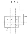
- the number of division can be arbitrary, and not necessarily be an integer. A case where the number of division is not an integer is shown in Fig. 9.
- Fig. 9 is an explanatory view for explaining an example when the photo-sensing surface of the solar cell 104 is divided into six blocks.
- blocks B1, B2, B4 and B5 have the same area as that of the opening of the mask 102, i.e., illuminated area.
- blocks B3 and B6 have smaller area than that of the illuminated area.
- the area where the photo-sensing surface exists is calculated as an effective illuminated area, then the similar calculation as described above is to be performed.
- the characteristic of the solar cell when the entire surface of the solar cell is illuminated is obtained by performing the foregoing method on the basis of the characteristics obtained by illuminating the photo-sensing surface of the solar cell by part (corresponding to, e.g., the B1-bright, B2B3B4-dark characteristic, and referred to as "partial bright characteristic” hereinafter) and the dark characteristic.
- part corresponding to, e.g., the B1-bright, B2B3B4-dark characteristic, and referred to as "partial bright characteristic” hereinafter
- the dark characteristic In order to obtain a more accurate result, it is preferable to perform following correction.
- a series resistance component as shown by an equivalent circuit in Fig. 10.
- reference numeral 1001 denotes an ideal solar cell having no series resistance component
- reference numeral 1002 denotes the series resistance component. Therefore, the voltage measured for obtaining the voltage/current characteristic corresponds to an ideal output voltage of the solar cell 1001 subtracted by a voltage drop due to the series resistance component 1002.
- the current values which are the base of calculations, are changed upon measuring the dark characteristic and the partial bright characteristic; therefore, they are affected by the voltage drop due to the series resistance component.
- it is the ideal solar cell 1001 that changes its characteristic depending upon the illuminated state; therefore, it is necessary to correct the measured characteristic of the voltage drop component due to the series resistance component 1002.
- a characteristic is calculated by eliminating the voltage drop component due to the series resistance component 1002 from the dark characteristic and the partial bright characteristic.
- the voltage drop component that is a product of the current value and the series resistance component 1002 at each measurement point is added to the voltage value measured at the corresponding point, and the sum is considered as the actual voltage value at each measurement point.
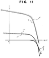
- Fig. 11 is a graph showing a result of the correction for the series resistance component 1002. In Fig. 11, a curve D shows the measured dark characteristic, and a curve D' shows the dark characteristic corrected for the voltage drop due to the series resistance component 1002.
- a curve P shows the partial bright characteristic when a block of the photo-sensing surface of the solar cell is illuminated
- a curve P' shows the partial bright characteristic corrected for the voltage drop due to the series resistance component 1002.
- a curve L' shows the characteristic of the solar cell when the entire surface is illuminated obtained on the basis of the corrected dark characteristic represented by the curve D' and the corrected partial bright characteristic represented by the curve P'.
- the curve L is the characteristic which is supposed to be measured by a voltmeter (corresponds to 205 in Fig. 2), and here, it is obtained by subtracting the voltage drop due to the series resistance component from the curve L' (inverse-correction).
- the curve L shown in Fig. 11 in the aforesaid operation is the characteristic measured of the entire solar cell.
- the correction for the voltage drop due to the series resistance component 1002 is necessary if a precise output of the solar cell is desired. However, since calculation load increases with precision, if very high precision is not required, this operation is unnecessary.
- the value of the series resistance component 1002 may be obtained by adding series resistances of, e.g., a transparent electrode and a base electrode, for instance, included in the solar cell, or obtained from the slope of the measured characteristic curve, i.e., ⁇ V/ ⁇ I.
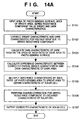
- Figs. 14A and 14B are flowcharts showing calculation sequences for obtaining the characteristic of the solar cell . The calculation is performed by the computer 207 shown in Fig. 2.
- the sequence shown in Fig. 14A is for calculating the characteristic of the solar cell in a state corresponding to that the entire photo-sensing surface being illuminated, on the basis of the measured partial bright characteristics when each block having a predetermined area of the photo-sensing surface of the solar cell is sequentially illuminated.
- an area corresponding to the illuminated block is called “bright area”
- the rest of the photo-sensing surface which is not illuminated is called "dark area”.
- step S101 necessary parameters, i.e., an area S of the photo-sensing surface, an area S 1 of the bright area, a value of the series resistance component of the solar cell, the measured a partial bright characteristic and a dark characteristic are inputted.
- step S102 correction for the voltage drop due to the series resistance component is performed on the partial bright characteristic and the dark characteristic.
- step S104 difference characteristic between the corrected partial bright characteristic and dark characteristic is calculated.
- step S106 the voltage/current characteristic obtained in step S105 is further applied with inverse-correction for the series resistance component. Then in step S107, the corrected characteristic of the solar cell is outputted.
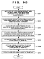
- the sequence shown in Fig. 14B is for calculating the characteristic of the solar cell in a state corresponding to that the entire photo-sensing surface of the solar cell is illuminated, on the basis of the partial bright characteristics obtained by illuminating each of a plurality of blocks obtained by dividing the photo-sensing surface of the solar cell.
- step S201 necessary parameters, i.e., an area S of the photo-sensing surface, an area of the bright area, a value of the series resistance component of the solar cell, the measured partial bright characteristic of each block and the measured dark characteristic are inputted.
- step S202 correction for the voltage drop due to the series resistance component is performed on the partial bright characteristic of each block and the dark characteristic.
- step S203 the corrected dark characteristic is multiplied by a ratio of an area S D of dark area to the area S of the photo-sensing surface; thereby a dark characteristic of the dark area is calculated.
- step S204 a difference characteristic between the corrected partial bright characteristic of each block and the corrected dark characteristic of the dark area is calculated.
- step S205 all the obtained difference characteristics are added; thereby a voltage/current characteristic in a state corresponding to that the entire photo-sensing surface of the solar cell is illuminated is calculated.
- step S206 the voltage/current characteristic obtained in step S205 is further applied with inverse-correction for the series resistance component.
- step S207 the corrected characteristic of the solar cell is outputted.
- the obtained result may be displayed on a monitor, or plotted by a plotter or a printer, in a form of characteristic curve.
- data representing the characteristic of the solar cell may be outputted to other computer or a printer.
- the characteristic of the solar cell corresponding to a state corresponding to that the entire photo-sensing surface is illuminated is obtained by performing the following calculations. It is assumed that the characteristic of the solar cell is the same over the surface, and the illuminated portion is one.
- the apparatus For measuring the characteristic of the solar cell, the apparatus, such as the one shown in Fig. 1, with the light source 101 capable of effectively illuminating an area of 225 cm 2 , 15 cm each side, is used.
- the mask 102 has a square shape of 20 cm each side, with a square opening, 5 cm each side.
- the solar cell 104 a triple-structure amorphous silicon solar cell having a square shape of 10 cm each side is used.
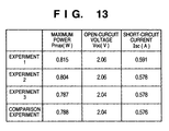
- the solar cell 104 is set on the sample holding stage 105, and the characteristic of the solar cell is measured in the method described above. The measurement result is shown in Fig. 13.
- the photo-sensing surface of the square solar cell 10 cm each side, is divided into four square blocks, 5 cm each side, and a characteristic is measured for each block.
- the characteristics of the solar cell is not the same over the photo-sensing surface, after the characteristic of each block is obtained, the characteristics of the four blocks are added to obtain a characteristic of the solar cell in a state corresponding to that the entire photo-sensing surface is illuminated. Note, other conditions are set identical to those in the experiment 1.
- the measurement result is shown in Fig. 13.
- a voltage drop due to a series resistance component of the solar cell is corrected to obtain the characteristic of the solar cell in a state corresponding to that the entire surface of the solar cell is illuminated.
- Other conditions are set identical to those in the experiment 2.
- the measurement result is shown in Fig. 13.
- a characteristic of the solar cell is measured without the mask 102 so that the entire photo-sensing surface of the square solar cell, 10 cm each side, is illuminated at once.
- this condition corresponds to a conventional measuring method of measuring a characteristic of a solar cell while illuminating the entire photo-sensing surface.
- Other conditions are set identical to those in the experiment 1. The measurement result is shown in Fig. 13.
- Fig. 13 is a table showing the measurement results of the characteristics of the solar cell obtained in the above respective experiments. From this result, the followings are concluded.
- the square solar cell having relatively small photo-receiving surface i.e., 10 cm each side. This is to verify whether the characteristic of the solar cell measured by using the measuring method of the present invention matches the characteristic measured by using the conventional measuring method as performed in the comparison experiment.
- a characteristic of a solar cell having a larger photo-sensing surface, too large to prepare a light source capable of illuminating the entire surface at once, than an area effectively illuminated by a light source is measured by using a light source capable of effectively illuminating a smaller area than the photo-sensing surface of the solar cell.
- a light source may be further down-sized, thereby reducing the cost of the measuring apparatus for measuring a characteristic of a solar cell. Consequently, the manufacture cost of a solar cell is reduced, thereby it is possible to provide an inexpensive solar cell.
- the sequences may be applied to characteristic inspection and product inspection when manufacturing the solar cell. Therefore, a manufacturing sequence including the measuring method of measuring a characteristic of a solar cell as shown by Figs. 12, 14A and 14B, and a solar cell produced in the manufacturing sequence are also included in the present invention.
- sequences for measuring a characteristic of a solar cell as shown by Figs. 12, 14A and 14B of the present invention can be also achieved by providing a storage medium storing program codes for performing the processes of the sequence to a computer system or apparatus (e.g., a personal computer), reading the program codes with CPU or MPU of the computer system or apparatus from the storage medium, then executing the program.
- a computer system or apparatus e.g., a personal computer
- the program codes read from the storage medium realize the functions according to the embodiment, and the storage medium storing the program codes constitutes the invention.
- the storage medium such as a floppy disk, a hard disk, an optical disk, a magneto-optical disk, CD-ROM, CD-R, a magnetic tape, a non-volatile type memory card, and ROM can be used for providing the program codes.
- the present invention includes a case where an OS (operating system) or the like working on the computer performs a part or entire processes in accordance with designations of the program codes and realizes functions according to the above embodiment.
- the present invention also includes a case where, after the program codes read from the storage medium are written in a function expansion card which is inserted into the computer or in a memory provided in a function expansion unit which is connected to the computer, CPU or the like contained in the function expansion card or unit performs a part or entire process in accordance with designations of the program codes and realizes functions of the above embodiment.
- a predetermined area of a photo-sensing surface of a solar cell is illuminated, and a voltage vs. current characteristic is measured.
- the rest of the photo-sensing surface which is not illuminated is called a dark area.
- a dark characteristic of the solar cell is measured.
- the obtained dark characteristic is multiplied by a ratio of the area of the dark area to the area of the photo-sensing surface, thereby a dark characteristic of the dark area is calculated.
- a difference characteristic between the measured voltage vs. current characteristic and the dark characteristic of the dark area is calculated.
- the difference characteristic is multiplied by a ratio of the area of the photo-sensing surface to the area of the illuminated portion, thereby a voltage vs. current characteristic of the solar cell in a state corresponding to that the entire area of the photo-sensing surface is illuminated at once is obtained.
Landscapes
- Physics & Mathematics (AREA)
- General Physics & Mathematics (AREA)
- Photovoltaic Devices (AREA)
- Testing Of Individual Semiconductor Devices (AREA)
- Testing Or Measuring Of Semiconductors Or The Like (AREA)
Abstract
Description
Claims (20)
- A measuring method of measuring a characteristic of a solar cell comprising the steps of:measuring a first characteristic of the solar cell while illuminating a predetermined area of a photo-sensing surface of the solar cell, wherein an area of the photo-sensing surface which is not illuminated is called a dark area;measuring a second characteristic of the solar cell in a dark state in which the photo-sensing surface is shielded from light;calculating a third characteristic by multiplying the second characteristic by an area ratio of an area of the dark area to an area of the photo-sensing surface; andcalculating a characteristic of the predetermined illuminated area on the basis of the first and third characteristics.
- The method according to claim 1, wherein the characteristic of the solar cell is a voltage vs. current characteristic of the solar cell.
- The method according to claim 1, wherein the characteristic calculated on the basis of the first and third characteristics corresponds to a voltage vs. current characteristic of the predetermined illuminated area when the illuminated area is physically separated from the rest of the area of the photo-sensing surface.
- The method according to claim 1, further comprising a step of calculating the characteristic of the solar cell by multiplying the characteristic calculated on the basis of the first and third characteristics by a ratio of an area of the photo-sensing surface to an area of the predetermined illuminated area.
- The method according to claim 1, further comprising a step of correcting the first and second characteristics for a voltage drop due to a series resistance component of the solar cell.
- The method according to claim 4, further comprising a step of performing inverse-correction for a voltage drop due to a series resistance component of the solar cell on the calculated characteristic of the solar cell.
- A measuring method of measuring a characteristic of a solar cell comprising the steps of:segmenting a photo-sensing surface of the solar cell into a plurality of blocks each having a predetermined area;measuring a first characteristic of the solar cell while illuminating each of the plurality of blocks, wherein an area of the photo-sensing surface which is not illuminated is called dark area;measuring a second characteristic of the solar cell in a dark state in which the photo-sensing surface is shielded from light;calculating a third characteristic by multiplying the second characteristic by an area ratio of an area of the dark area to an area of the photo-sensing surface; andcalculating a characteristic of each of the plurality of the segmented block on the basis of the first and third characteristics of the corresponding block.
- The method according to claim 7, wherein the characteristic of the solar cell is a voltage vs. current characteristic of the solar cell.
- The method according to claim 7, wherein the characteristic calculated on the basis of the first and third characteristics of each of the plurality of the segmented blocks corresponds to a voltage vs. current characteristic of each block when the plurality of blocks are physically separated from each other.
- The method according to claim 7, further comprising a step of calculating the characteristic of the solar cell by adding the characteristics of the plurality of blocks.
- The method according to claim 7, further comprising a step of correcting the first and second characteristics for a voltage drop due to a series resistance component of the solar cell.
- The method according to claim 10, further comprising a step of performing inverse-correction for a voltage drop due to a series resistance component of the solar cell on the calculated characteristic of the solar cell.
- A manufacturing method of manufacturing a solar cell comprising a measuring step of measuring a characteristic of the solar cell in accordance with the measuring method according to claim 1.
- A solar cell produced by the manufacturing method according to claim 13.
- A manufacturing method of manufacturing a solar cell comprising a measuring step of measuring a characteristic of the solar cell in accordance with the measuring method according to claim 7.
- A solar cell produced by the manufacturing method according to claim 15.
- A measuring apparatus for measuring a characteristic of a solar cell, comprising:a light source for illuminating a photo-sensing surface of the solar cell; anda mask, provided between the photo-sensing surface and said light source, for limiting an area to be illuminated on the photo-sensing surface to a predetermined area.
- The apparatus according to claim 17, further comprising a movement unit for moving said mask so that a predetermined area on the photo-sensing surface is illuminated by said light source.
- A computer program product comprising a computer readable medium having computer program code, for measuring a characteristic of a solar cell, said product comprising:first measuring process procedure code for measuring a first characteristic of the solar cell while illuminating a predetermined area of a photo-sensing surface of the solar cell, wherein an area of the photo-sensing surface which is not illuminated is called a dark area;second measuring process procedure code for measuring a second characteristic of the solar cell in a dark state in which the photo-sensing surface is shielded from light;first calculation process procedure code for calculating a third characteristic by multiplying the second characteristic by an area ratio of an area of the dark area to an area of the photo-sensing surface; andsecond calculation process procedure code for calculating a characteristic of the predetermined illuminated area on the basis of the first and third characteristics.
- A computer program product comprising a computer readable medium having computer program code, for measuring a characteristic of a solar cell, said product comprising:first measuring process procedure code for measuring a first characteristic of the solar cell while illuminating each of a plurality of blocks obtained by segmenting a photo-sensing area of the solar cell, wherein an area of the photo-sensing surface which is not illuminated is called dark area;second measuring process procedure code for measuring a second characteristic of the solar cell in a dark state in which the photo-sensing surface is shielded from light;first calculation process procedure code for calculating a third characteristic by multiplying the second characteristic by an area ratio of an area of the dark area to an area of the photo-sensing surface; andsecond calculation process procedure code for calculating a characteristic of each of the plurality of the segmented block on the basis of the first and third characteristics of the corresponding block.
Applications Claiming Priority (3)
| Application Number | Priority Date | Filing Date | Title |
|---|---|---|---|
| JP17489097 | 1997-06-30 | ||
| JP17489097A JP3647209B2 (en) | 1997-06-30 | 1997-06-30 | Measuring method of solar cell characteristics |
| JP174890/97 | 1997-06-30 |
Publications (2)
| Publication Number | Publication Date |
|---|---|
| EP0887652A2 true EP0887652A2 (en) | 1998-12-30 |
| EP0887652A3 EP0887652A3 (en) | 2003-04-23 |
Family
ID=15986476
Family Applications (1)
| Application Number | Title | Priority Date | Filing Date |
|---|---|---|---|
| EP98111624A Ceased EP0887652A3 (en) | 1997-06-30 | 1998-06-24 | Measuring apparatus and method for measuring characteristic of solar cell |
Country Status (6)
| Country | Link |
|---|---|
| US (2) | US6169414B1 (en) |
| EP (1) | EP0887652A3 (en) |
| JP (1) | JP3647209B2 (en) |
| KR (1) | KR100350861B1 (en) |
| CN (1) | CN1140813C (en) |
| AU (1) | AU728121B2 (en) |
Cited By (9)
| Publication number | Priority date | Publication date | Assignee | Title |
|---|---|---|---|---|
| EP1199576A1 (en) * | 2000-10-17 | 2002-04-24 | Drei Solar AG | Device for testing solar cells |
| WO2002033430A1 (en) * | 2000-10-17 | 2002-04-25 | Acr Automation In Cleanroom Gmbh | Device for testing solar cells |
| EP1170596A3 (en) * | 2000-07-04 | 2006-01-04 | Canon Kabushiki Kaisha | Method and apparatus for measuring photoelectric conversion characteristics |
| EP1686386A1 (en) * | 2005-02-01 | 2006-08-02 | Nisshinbo Industries, Inc. | Method and apparatus to measure the current-voltage characteristics of photovoltaic devices and to equalize the irradiance of a solar simulator |
| WO2009103566A3 (en) * | 2008-02-22 | 2009-12-17 | Fraunhofer-Gesellschaft zur Förderung der angewandten Forschung e.V. | Measuring method and device for characterizing a semiconductor component |
| WO2012170191A1 (en) * | 2011-06-10 | 2012-12-13 | The Boeing Company | Solar cell testing apparatus and method |
| CN103018658A (en) * | 2012-12-27 | 2013-04-03 | 中国人民解放军海军航空工程学院 | Circuit board health condition monitoring method based on volt-ampere characteristic curves |
| EP2581755A1 (en) * | 2011-10-11 | 2013-04-17 | Kema Nederland B.V. | Method and device for testing a solar panel |
| CN111237681A (en) * | 2020-02-25 | 2020-06-05 | 飞率有限公司 | Day-type hybrid ultra-precise artificial sunlight simulation device and simulation method |
Families Citing this family (63)
| Publication number | Priority date | Publication date | Assignee | Title |
|---|---|---|---|---|
| JP2001076282A (en) * | 1999-09-02 | 2001-03-23 | Canon Inc | Information processing apparatus and method |
| KR20010079059A (en) * | 2001-06-11 | 2001-08-22 | 김태엽 | Parameter estimation algorithm and measurement equipment of solar cell |
| JP2004134748A (en) * | 2002-07-26 | 2004-04-30 | Canon Inc | Measuring method and apparatus for photoelectric conversion device, and manufacturing method and apparatus for the photoelectric conversion device |
| JP2004273245A (en) | 2003-03-07 | 2004-09-30 | Canon Inc | Simulated sunlight irradiation method and apparatus |
| JP4139890B2 (en) * | 2003-03-13 | 2008-08-27 | 独立行政法人産業技術総合研究所 | Method for evaluating characteristics of solar cells |
| JP2005005639A (en) * | 2003-06-16 | 2005-01-06 | Canon Inc | Method and apparatus for measuring photoelectric conversion characteristics of solar cell element |
| CN1300597C (en) * | 2004-03-15 | 2007-02-14 | 东南大学 | Integrated assayer for photoelectric performance |
| CN100357755C (en) * | 2004-04-22 | 2007-12-26 | 上海交通大学 | Testing method for effective diffusion length of solar cell |
| JP2006228926A (en) * | 2005-02-17 | 2006-08-31 | Fuji Electric Holdings Co Ltd | Measuring method of current-voltage characteristics of solar cell module |
| JP4696308B2 (en) * | 2007-01-09 | 2011-06-08 | 独立行政法人産業技術総合研究所 | Method for evaluating characteristics of solar cells |
| US20080257397A1 (en) * | 2007-04-17 | 2008-10-23 | John Stanley Glaser | System, method, and apparatus for extracting power from a photovoltaic source of electrical energy |
| CN101311742B (en) * | 2007-05-22 | 2010-10-06 | 中芯国际集成电路制造(上海)有限公司 | A method for testing the efficiency of solar cell modules |
| US7667479B2 (en) * | 2007-10-31 | 2010-02-23 | Atomic Energy Council | Apparatus for testing concentration-type solar cells |
| CN101241039B (en) * | 2008-02-01 | 2010-04-14 | 苏州纳米技术与纳米仿生研究所 | A method and component for testing the photoelectric performance of a double-sided chip |
| KR101197807B1 (en) * | 2008-03-26 | 2012-11-05 | 엔페이즈 에너지, 인코포레이티드 | Method and apparatus for measuring ac voltages |
| US8037327B2 (en) * | 2008-03-31 | 2011-10-11 | Agilent Technologies, Inc. | System and method for improving dynamic response in a power supply |
| TWI443850B (en) | 2008-05-09 | 2014-07-01 | Ind Tech Res Inst | Solar cell testing machine |
| CN101598764B (en) * | 2008-06-06 | 2012-01-25 | 财团法人工业技术研究院 | Solar battery testing machine |
| EP3193101A1 (en) * | 2008-07-09 | 2017-07-19 | Skyfuel, Inc. | Solar collectors having slidably removable reflective panels for use in solar thermal applications |
| US8739492B2 (en) | 2008-07-09 | 2014-06-03 | Skyfuel, Inc. | Space frame connector |
| WO2010022280A1 (en) * | 2008-08-22 | 2010-02-25 | Skyfuel, Inc. | Hydraulic-based rotational system for solar concentrators that resists high wind loads without a mechanical lock |
| US20100073011A1 (en) * | 2008-09-23 | 2010-03-25 | Applied Materials, Inc. | Light soaking system and test method for solar cells |
| GB0821146D0 (en) | 2008-11-19 | 2008-12-24 | Univ Denmark Tech Dtu | Method of testing solar cells |
| WO2010083292A1 (en) * | 2009-01-14 | 2010-07-22 | Skyfuel, Inc. | Apparatus and method for building linear solar collectors directly from rolls of reflective laminate material |
| US20100237895A1 (en) * | 2009-03-19 | 2010-09-23 | Kyo Young Chung | System and method for characterizing solar cell conversion performance and detecting defects in a solar cell |
| US20100236035A1 (en) * | 2009-03-19 | 2010-09-23 | Kyo Young Chung | System and method for detecting defects in a solar cell and repairing and characterizing a solar cell |
| KR101121451B1 (en) * | 2009-04-20 | 2012-03-15 | 한국표준과학연구원 | Apparatus and method for inspecting quantum efficiency homogeneity of solar cell using imaging device |
| DE102009021799A1 (en) * | 2009-05-18 | 2010-11-25 | Fraunhofer-Gesellschaft zur Förderung der angewandten Forschung e.V. | Method for the spatially resolved determination of the series resistance of a semiconductor structure |
| JP4570680B1 (en) * | 2009-06-12 | 2010-10-27 | シャープ株式会社 | Light irradiation device and inspection device |
| US8749256B2 (en) * | 2009-09-03 | 2014-06-10 | Tel Solar Ag | Measurement system |
| US8159238B1 (en) | 2009-09-30 | 2012-04-17 | The United States Of America As Represented By The Administrator Of The National Aeronautics And Space Administration | Method and apparatus for in-situ health monitoring of solar cells in space |
| US10396709B2 (en) | 2009-09-30 | 2019-08-27 | United States Of America As Represented By The Administrator Of National Aeronautics And Space Administration | Method and apparatus for in-situ health monitoring of solar cells in space |
| US20120056638A1 (en) * | 2010-03-10 | 2012-03-08 | Alion, Inc. | Systems and methods for monitoring and diagnostics of photovoltaic solar modules in photovoltaic systems |
| TWI397708B (en) * | 2010-04-06 | 2013-06-01 | Ind Tech Res Inst | Solar cell measurement system and solar simulator |
| KR101049450B1 (en) * | 2010-04-14 | 2011-07-15 | 한국표준과학연구원 | Optical device and its correction method |
| US9462734B2 (en) | 2010-04-27 | 2016-10-04 | Alion Energy, Inc. | Rail systems and methods for installation and operation of photovoltaic arrays |
| TWI400459B (en) * | 2010-06-23 | 2013-07-01 | Nat Univ Tsing Hua | A method for parameters extraction of solar cells |
| US9343592B2 (en) | 2010-08-03 | 2016-05-17 | Alion Energy, Inc. | Electrical interconnects for photovoltaic modules and methods thereof |
| US20130200918A1 (en) * | 2010-10-18 | 2013-08-08 | Day4 Energy Group Inc. | Testing apparatus for photovoltaic cells |
| CN102103104A (en) * | 2010-12-14 | 2011-06-22 | 天津市津能电池科技有限公司 | Method for detecting laser etching effect of amorphous solar cells |
| KR101213059B1 (en) | 2011-02-23 | 2012-12-18 | 광운대학교 산학협력단 | System of measuring solar cell and controlling method therefor |
| US8797058B2 (en) * | 2011-03-03 | 2014-08-05 | International Business Machines Corporation | Solar cell characterization system with an automated continuous neutral density filter |
| US8860424B1 (en) * | 2011-03-10 | 2014-10-14 | Solar Junction Corporation | Apparatus and method for highly accelerated life testing of solar cells |
| US9641123B2 (en) | 2011-03-18 | 2017-05-02 | Alion Energy, Inc. | Systems for mounting photovoltaic modules |
| US8350585B2 (en) * | 2011-05-31 | 2013-01-08 | Primestar Solar, Inc. | Simultaneous QE scanning system and methods for photovoltaic devices |
| US9246434B2 (en) | 2011-09-26 | 2016-01-26 | First Solar, Inc | System and method for estimating the short circuit current of a solar device |
| CN102361048B (en) * | 2011-10-21 | 2016-06-15 | 中国电子科技集团公司第十八研究所 | The preparation method of a kind of standard solar cells |
| US9352941B2 (en) | 2012-03-20 | 2016-05-31 | Alion Energy, Inc. | Gantry crane vehicles and methods for photovoltaic arrays |
| CN104412026A (en) | 2012-05-16 | 2015-03-11 | 阿利昂能源公司 | Rotatable support systems for photovoltaic modules and methods thereof |
| CN102680434B (en) * | 2012-05-16 | 2014-06-18 | 华中科技大学 | Light current spectrum high throughput testing device of materials under atmosphere environment |
| US8952715B2 (en) | 2012-11-14 | 2015-02-10 | Stratasense LLC | Wireless current-voltage tracer with uninterrupted bypass system and method |
| CN103207363B (en) * | 2013-04-21 | 2016-02-10 | 南昌航空大学 | A kind of instrument measuring solar cell parameter |
| DE102013226885A1 (en) * | 2013-06-03 | 2014-12-04 | Kyoshin Electric Co., Ltd | I-U characteristic measuring method and I-U characteristic measuring device for solar cells as well as program for I-U characteristic measuring device |
| JP6475246B2 (en) | 2013-09-05 | 2019-02-27 | アリオン エナジー,インコーポレーテッド | System, vehicle and method for maintaining a rail-based array of photovoltaic modules |
| US9453660B2 (en) | 2013-09-11 | 2016-09-27 | Alion Energy, Inc. | Vehicles and methods for magnetically managing legs of rail-based photovoltaic modules during installation |
| CN104135231A (en) * | 2014-08-22 | 2014-11-05 | 张从尧 | Solar cell performance tester |
| US20160356646A1 (en) * | 2015-06-02 | 2016-12-08 | Kaiser Optical Systems Inc. | Methods for collection, dark correction, and reporting of spectra from array detector spectrometers |
| WO2017044566A1 (en) | 2015-09-11 | 2017-03-16 | Alion Energy, Inc. | Wind screens for photovoltaic arrays and methods thereof |
| CN106656043B (en) * | 2016-11-18 | 2019-12-03 | 南昌航空大学 | A solar cell test shading plate with precise and controllable shading area |
| US10720883B2 (en) | 2017-04-24 | 2020-07-21 | Angstrom Designs, Inc | Apparatus and method for testing performance of multi-junction solar cells |
| TWI698083B (en) * | 2019-03-19 | 2020-07-01 | 友達光電股份有限公司 | Surface dirt measurement method and measurement apparatus |
| FR3097705B1 (en) * | 2019-06-20 | 2021-07-02 | Commissariat Energie Atomique | ELECTRICAL CHARACTERIZATION PROCESS OF A CUT PHOTOVOLTAIC CELL |
| DE102020102494A1 (en) * | 2020-01-31 | 2021-08-05 | Heliatek Gmbh | Method for checking a photovoltaic element, as well as a photovoltaic element, checked according to such a method |
Family Cites Families (14)
| Publication number | Priority date | Publication date | Assignee | Title |
|---|---|---|---|---|
| US3630627A (en) * | 1970-02-27 | 1971-12-28 | Nasa | Solar cell assembly test method |
| JPS5097376U (en) * | 1973-12-29 | 1975-08-14 | ||
| US4205265A (en) * | 1978-08-21 | 1980-05-27 | Rca Corporation | Laser beam apparatus and method for analyzing solar cells |
| US4353161A (en) * | 1981-06-18 | 1982-10-12 | Atlantic Richfield Company | Process for fabricating solar to electrical energy conversion units |
| US4467438A (en) * | 1982-01-18 | 1984-08-21 | Dset Laboratories, Inc. | Method and apparatus for determining spectral response and spectral response mismatch between photovoltaic devices |
| US4419530A (en) | 1982-02-11 | 1983-12-06 | Energy Conversion Devices, Inc. | Solar cell and method for producing same |
| JPS5940588A (en) * | 1982-08-31 | 1984-03-06 | Toshiba Corp | Detecting device for abnormal solar battery element |
| US4533870A (en) * | 1982-11-29 | 1985-08-06 | The Boeing Company | Method for testing multi-section photo-sensitive detectors |
| US4712063A (en) * | 1984-05-29 | 1987-12-08 | The United States Of America As Represented By The United States Department Of Energy | Method and apparatus for measuring areas of photoelectric cells and photoelectric cell performance parameters |
| US4649334A (en) | 1984-10-18 | 1987-03-10 | Kabushiki Kaisha Toshiba | Method of and system for controlling a photovoltaic power system |
| JPH0864653A (en) * | 1994-08-26 | 1996-03-08 | Omron Corp | Solar cell diagnostic system |
| JP3270303B2 (en) * | 1995-07-26 | 2002-04-02 | キヤノン株式会社 | Battery power supply device characteristic measuring device and measuring method |
| FI106408B (en) * | 1996-03-20 | 2001-01-31 | Fortum Power & Heat Oy | Method and apparatus for measuring current voltage characteristics of solar panels |
| US6154034A (en) * | 1998-10-20 | 2000-11-28 | Lovelady; James N. | Method and apparatus for testing photovoltaic solar cells using multiple pulsed light sources |
-
1997
- 1997-06-30 JP JP17489097A patent/JP3647209B2/en not_active Expired - Fee Related
-
1998
- 1998-06-24 EP EP98111624A patent/EP0887652A3/en not_active Ceased
- 1998-06-29 AU AU73925/98A patent/AU728121B2/en not_active Ceased
- 1998-06-29 CN CNB981151930A patent/CN1140813C/en not_active Expired - Fee Related
- 1998-06-30 KR KR1019980025487A patent/KR100350861B1/en not_active Expired - Fee Related
- 1998-06-30 US US09/106,469 patent/US6169414B1/en not_active Expired - Lifetime
-
2000
- 2000-10-19 US US09/691,130 patent/US6639421B1/en not_active Expired - Fee Related
Cited By (14)
| Publication number | Priority date | Publication date | Assignee | Title |
|---|---|---|---|---|
| EP1170596A3 (en) * | 2000-07-04 | 2006-01-04 | Canon Kabushiki Kaisha | Method and apparatus for measuring photoelectric conversion characteristics |
| EP1199576A1 (en) * | 2000-10-17 | 2002-04-24 | Drei Solar AG | Device for testing solar cells |
| WO2002033430A1 (en) * | 2000-10-17 | 2002-04-25 | Acr Automation In Cleanroom Gmbh | Device for testing solar cells |
| US8315848B2 (en) | 2005-02-01 | 2012-11-20 | Nisshinbo Industries, Inc. | Measurement method of the current-voltage characteristics of photovoltaic device, a solar simulator for the measurement, and a module for setting irradiance and a part for adjusting irradiance used for the solar simulator |
| US7528615B2 (en) | 2005-02-01 | 2009-05-05 | Nisshinbo Industries, Inc. | Measurement method of the current-voltage characteristics of photovoltaic devices, a solar simulator for the measurement, and a module for setting irradiance and a part for adjusting irradiance used for the solar simulator |
| EP1686386A1 (en) * | 2005-02-01 | 2006-08-02 | Nisshinbo Industries, Inc. | Method and apparatus to measure the current-voltage characteristics of photovoltaic devices and to equalize the irradiance of a solar simulator |
| WO2009103566A3 (en) * | 2008-02-22 | 2009-12-17 | Fraunhofer-Gesellschaft zur Förderung der angewandten Forschung e.V. | Measuring method and device for characterizing a semiconductor component |
| US8829938B2 (en) | 2008-02-22 | 2014-09-09 | Fraunhofer-Gesellschaft zur Föderung der angewandten Forschung e.V. | Measuring method and device for characterizing a semiconductor component |
| WO2012170191A1 (en) * | 2011-06-10 | 2012-12-13 | The Boeing Company | Solar cell testing apparatus and method |
| US9863890B2 (en) | 2011-06-10 | 2018-01-09 | The Boeing Company | Solar cell testing apparatus and method |
| EP2581755A1 (en) * | 2011-10-11 | 2013-04-17 | Kema Nederland B.V. | Method and device for testing a solar panel |
| CN103018658A (en) * | 2012-12-27 | 2013-04-03 | 中国人民解放军海军航空工程学院 | Circuit board health condition monitoring method based on volt-ampere characteristic curves |
| CN103018658B (en) * | 2012-12-27 | 2015-02-04 | 中国人民解放军海军航空工程学院 | Circuit board health condition monitoring method based on volt-ampere characteristic curves |
| CN111237681A (en) * | 2020-02-25 | 2020-06-05 | 飞率有限公司 | Day-type hybrid ultra-precise artificial sunlight simulation device and simulation method |
Also Published As
| Publication number | Publication date |
|---|---|
| CN1204059A (en) | 1999-01-06 |
| AU7392598A (en) | 1999-01-14 |
| EP0887652A3 (en) | 2003-04-23 |
| AU728121B2 (en) | 2001-01-04 |
| KR19990007476A (en) | 1999-01-25 |
| US6169414B1 (en) | 2001-01-02 |
| JP3647209B2 (en) | 2005-05-11 |
| JPH1126785A (en) | 1999-01-29 |
| KR100350861B1 (en) | 2002-11-18 |
| CN1140813C (en) | 2004-03-03 |
| US6639421B1 (en) | 2003-10-28 |
Similar Documents
| Publication | Publication Date | Title |
|---|---|---|
| US6169414B1 (en) | Measuring apparatus and method for measuring characteristic of solar cell | |
| US5955885A (en) | Battery power supply device characteristic measuring apparatus and measuring method | |
| TWI413270B (en) | Method for forming optimal characteristic curves of solar cell and system thereof | |
| US20160204737A1 (en) | I-v measurement system for photovoltaic modules | |
| US9207283B2 (en) | Universal battery charger and method of use thereof | |
| Schuss et al. | Detecting defects in photovoltaic panels with the help of synchronized thermography | |
| WO1983002512A1 (en) | Method and apparatus for determining spectral response and spectral response mismatch between photovoltaic devices | |
| KR20100072457A (en) | Analysis device of solar cell module character, and thereof method | |
| JP3560308B2 (en) | Solar cell quality judgment method | |
| De Riso et al. | Enhanced photovoltaic panel diagnostics: Advancing a high-precision and low-cost I–V curve tracer | |
| Eikelboom et al. | Characterisation of PV modules of new generations | |
| CN108923750B (en) | Photovoltaic device capacitance-voltage characteristic curve test method | |
| Antón et al. | Performance prediction of concentrator solar cells and modules from dark I–V characteristics | |
| CN116232223A (en) | Solar cell reliability test system and test method | |
| Eisgruber et al. | Extraction of individual‐cell photocurrents and shunt resistances in encapsulated modules using large‐scale laser scanning | |
| Wu et al. | An electric circuit model of photovoltaic panel with power electronic converter | |
| Cotfas et al. | Current-voltage characteristic raising techniques for solar cells. Comparisons and applications | |
| Ramaprabha et al. | Development of an improved model of SPV cell for partially shaded solar photovoltaic arrays | |
| US20250023516A1 (en) | Contact device and arrangement and method for characterizing sub-cells | |
| Bothe et al. | Contacting of busbarless solar cells for accurate IV measurements | |
| CN116647183A (en) | Photovoltaic array power generation performance determination method, device and photovoltaic system | |
| CN223168297U (en) | Photovoltaic module's accredited testing organization | |
| JPH11340488A (en) | Method and apparatus for measuring characteristics of photovoltaic module and manufacturing method | |
| Oražem et al. | Improving IV Curve Measurement Accuracy of High-Efficiency PV Modules Using Extrapolation Based on a Dual Load Capacitor Scanning Method | |
| JP2006228926A (en) | Measuring method of current-voltage characteristics of solar cell module |
Legal Events
| Date | Code | Title | Description |
|---|---|---|---|
| PUAI | Public reference made under article 153(3) epc to a published international application that has entered the european phase |
Free format text: ORIGINAL CODE: 0009012 |
|
| AK | Designated contracting states |
Kind code of ref document: A2 Designated state(s): AT BE CH CY DE DK ES FI FR GB GR IE IT LI LU MC NL PT SE |
|
| AX | Request for extension of the european patent |
Free format text: AL;LT;LV;MK;RO;SI |
|
| PUAL | Search report despatched |
Free format text: ORIGINAL CODE: 0009013 |
|
| AK | Designated contracting states |
Designated state(s): AT BE CH CY DE DK ES FI FR GB GR IE IT LI LU MC NL PT SE |
|
| AX | Request for extension of the european patent |
Extension state: AL LT LV MK RO SI |
|
| 17P | Request for examination filed |
Effective date: 20030902 |
|
| AKX | Designation fees paid |
Designated state(s): CH DE IT LI |
|
| 17Q | First examination report despatched |
Effective date: 20031203 |
|
| STAA | Information on the status of an ep patent application or granted ep patent |
Free format text: STATUS: THE APPLICATION HAS BEEN REFUSED |
|
| 18R | Application refused |
Effective date: 20050617 |