EP0887016B1 - spinning reel - Google Patents
spinning reel Download PDFInfo
- Publication number
- EP0887016B1 EP0887016B1 EP98304956A EP98304956A EP0887016B1 EP 0887016 B1 EP0887016 B1 EP 0887016B1 EP 98304956 A EP98304956 A EP 98304956A EP 98304956 A EP98304956 A EP 98304956A EP 0887016 B1 EP0887016 B1 EP 0887016B1
- Authority
- EP
- European Patent Office
- Prior art keywords
- rotor
- bail
- arm
- line
- rod
- Prior art date
- Legal status (The legal status is an assumption and is not a legal conclusion. Google has not performed a legal analysis and makes no representation as to the accuracy of the status listed.)
- Expired - Lifetime
Links
- 238000009987 spinning Methods 0.000 title claims description 33
- 230000007246 mechanism Effects 0.000 claims description 146
- 238000004804 winding Methods 0.000 claims description 54
- 230000000717 retained effect Effects 0.000 claims description 11
- 230000004044 response Effects 0.000 claims description 9
- 239000013013 elastic material Substances 0.000 claims description 5
- 230000002441 reversible effect Effects 0.000 description 19
- 238000005266 casting Methods 0.000 description 10
- XLYOFNOQVPJJNP-UHFFFAOYSA-N water Substances O XLYOFNOQVPJJNP-UHFFFAOYSA-N 0.000 description 2
- 239000000853 adhesive Substances 0.000 description 1
- 230000001070 adhesive effect Effects 0.000 description 1
- 230000008859 change Effects 0.000 description 1
- 230000007547 defect Effects 0.000 description 1
- 238000006073 displacement reaction Methods 0.000 description 1
- 230000000694 effects Effects 0.000 description 1
- 238000004519 manufacturing process Methods 0.000 description 1
- 239000000463 material Substances 0.000 description 1
- 230000004048 modification Effects 0.000 description 1
- 238000012986 modification Methods 0.000 description 1
- 238000003825 pressing Methods 0.000 description 1
- 230000009467 reduction Effects 0.000 description 1
- 229920002379 silicone rubber Polymers 0.000 description 1
- 239000004945 silicone rubber Substances 0.000 description 1
Images


Classifications
-
- A—HUMAN NECESSITIES
- A01—AGRICULTURE; FORESTRY; ANIMAL HUSBANDRY; HUNTING; TRAPPING; FISHING
- A01K—ANIMAL HUSBANDRY; AVICULTURE; APICULTURE; PISCICULTURE; FISHING; REARING OR BREEDING ANIMALS, NOT OTHERWISE PROVIDED FOR; NEW BREEDS OF ANIMALS
- A01K89/00—Reels
- A01K89/015—Reels with a rotary drum, i.e. with a rotating spool
-
- A—HUMAN NECESSITIES
- A01—AGRICULTURE; FORESTRY; ANIMAL HUSBANDRY; HUNTING; TRAPPING; FISHING
- A01K—ANIMAL HUSBANDRY; AVICULTURE; APICULTURE; PISCICULTURE; FISHING; REARING OR BREEDING ANIMALS, NOT OTHERWISE PROVIDED FOR; NEW BREEDS OF ANIMALS
- A01K89/00—Reels
- A01K89/01—Reels with pick-up, i.e. with the guiding member rotating and the spool not rotating during normal retrieval of the line
-
- A—HUMAN NECESSITIES
- A01—AGRICULTURE; FORESTRY; ANIMAL HUSBANDRY; HUNTING; TRAPPING; FISHING
- A01K—ANIMAL HUSBANDRY; AVICULTURE; APICULTURE; PISCICULTURE; FISHING; REARING OR BREEDING ANIMALS, NOT OTHERWISE PROVIDED FOR; NEW BREEDS OF ANIMALS
- A01K89/00—Reels
- A01K89/015—Reels with a rotary drum, i.e. with a rotating spool
- A01K89/0155—Antibacklash devices
-
- A—HUMAN NECESSITIES
- A01—AGRICULTURE; FORESTRY; ANIMAL HUSBANDRY; HUNTING; TRAPPING; FISHING
- A01K—ANIMAL HUSBANDRY; AVICULTURE; APICULTURE; PISCICULTURE; FISHING; REARING OR BREEDING ANIMALS, NOT OTHERWISE PROVIDED FOR; NEW BREEDS OF ANIMALS
- A01K89/00—Reels
- A01K89/015—Reels with a rotary drum, i.e. with a rotating spool
- A01K89/0183—Drive mechanism details
-
- A—HUMAN NECESSITIES
- A01—AGRICULTURE; FORESTRY; ANIMAL HUSBANDRY; HUNTING; TRAPPING; FISHING
- A01K—ANIMAL HUSBANDRY; AVICULTURE; APICULTURE; PISCICULTURE; FISHING; REARING OR BREEDING ANIMALS, NOT OTHERWISE PROVIDED FOR; NEW BREEDS OF ANIMALS
- A01K89/00—Reels
- A01K89/02—Brake devices for reels
Definitions
- the present invention relates to a spinning reel according to claim 1.
- a spinning reel has a reel body, a rotor rotatably supported to a reel body and a spool around which a fishing line is to be wound.
- the rotor has first and second arm portions disposed to face each other so as to clamp a rotary shaft, and a bail arm pivotally mounted at tip ends of the two arms.
- the bail arm has a pair of bail support members pivotally mounted on the first and second arm portions, respectively, a fishing line guide portion including a line roller mounted at a tip end of one of the bail support members, and a bail disposed between the fishing line guide portion and the other bail support member.
- the bail arm may be positioned in a line winding position for winding fishing line around the outer circumference of the spool and the bail arm may be pivoted to a line releasing position where the bail arm is tilted from the line winding position so as not to be an obstruction when the fishing line is fed out or cast out from the spool.
- a bail reversing device is provided on the rotor for maintaining the bail at the line winding position and at the line releasing position and for reversing the bail between the two positions.
- the bail reversing device has a return mechanism for automatically returning the bail back to the line winding position when the rotor is rotated by the handle while the bail is being kept in the line releasing position.
- the spinning reel has a reverse rotation preventing mechanism for preventing the rotor from rotating in a reverse direction (in the rotation in the line feeding direction).
- the reverse rotation preventing mechanism operates, the rotor is prevented from rotating in the reverse direction (a direction opposite the direction of rotation for winding line about the spool).
- the present invention is directed to making it possible to maintain, in a spinning reel, the rotational phase of the rotor with respect to the reel housing and to adjust the rotational position of the rotor when the bail arm is in the line releasing position.
- a rotor brake mechanism for a spinning reel includes a reel body and a rotor supported on the reel body for rotation in response to rotation of a handle which extends from the reel body.
- a bail arm is supported on the rotor, the bail arm being configured to pivot about a pivot axis defined on a portion of the rotor between a line winding position and a line releasing position.
- a brake member made of an elastic material has a ring shape and is disposed in a groove formed in the reel body adjacent to a portion of the rotor.
- a moving mechanism is supported within a portion of the rotor, the moving mechanism being configured to respond to movement of the bail arm such that a portion of the moving mechanism engages the braking member with the bail arm in the line releasing position.
- the moving mechanism includes a lever member pivotally mounted on the rotor for pivotal movement between a first position and a second position such that in the second position a portion of the lever member contacts the brake member and in the first position the lever member is spaced apart from the brake member.
- the moving mechanism further includes a cooperating mechanism for swinging the lever member toward the second position in cooperation with swing motion of the bail arm when the bail arm is swung from the line winding position to the line releasing position.
- a tip end portion of the lever member is configured for contact with the brake member and is formed with an arcuate shape with respect to a pivot axis about which the lever member pivots.
- a bail reversing mechanism is at least partially supported in the rotor.
- the reversing mechanism is configured to pivot the bail arm from the line releasing position to the line winding position in response to rotation of the rotor with respect to the reel body.
- the cooperating mechanism at least partially defines a portion of the bail reversing mechanism, and the moving mechanism is configured to maintain the bail arm in the line winding position and in the line releasing position.
- a spinning reel is mountable on a fishing rod for winding a fishing line by rotation of a handle.
- the spinning reel includes a reel body having a handle, the reel body being mountable on a fishing rod.
- a rotor having a first arm portion and a second arm portion disposed on opposite circumferential sides of the rotor facing each other, is supported rotatably to a front portion of the reel body.
- a bail arm is supported at tip ends of the first and second arm portions, the bail arm being pivotable about an axis extending between the tip ends of the first and second arm portions.
- the bail arm is pivotal between a line winding position and a line releasing position.
- a spool is supported on the reel body proximate a front portion of the rotor for winding the fishing line. Further, there is a rotor brake mechanism for braking the rotor when the bail arm is positioned in the line releasing position.
- the rotor further includes a bail reversing mechanism for maintaining the bail arm in the line winding position and the line releasing position and for moving the bail arm from the line releasing position to the line winding position in response to rotation of the rotor with respect to the reel body.
- a bail reversing mechanism for maintaining the bail arm in the line winding position and the line releasing position and for moving the bail arm from the line releasing position to the line winding position in response to rotation of the rotor with respect to the reel body.
- the bail arm has a first bail support member and a second bail support member pivotally mounted at the tip ends of the first and second arm portions and a bail extending between the first and second bail support members.
- the bail reversing mechanism includes a toggle mechanism which maintains position of the bail arm where the bail arm is in one of the line winding position and the line releasing position.
- the bail reversing mechanism further includes a protrusion formed on the reel body so as to be contactable with a portion of the toggle mechanism with the bail arm in the line releasing position such that in response to contact with the protrusion the toggle mechanism urges the bail arm from the line releasing position toward the line winding position.
- the rotor brake mechanism is defined by a portion of the toggle mechanism and the rotor brake mechanism is further defined by a brake member disposed on the reel body.
- the brake member is contactable with a portion of the toggle mechanism for braking the rotor with the bail arm in the line releasing position.
- a spinning reel in accordance with a third aspect of the present invention, includes a reel body mountable on a fishing rod and a rotor formed with a first arm portion and a second arm portion disposed to face each other on opposite circumferential sides thereof.
- A, bail arm extends between tip ends of the first and second arm portions.
- the bail arm is reversible between a line winding position and a line releasing position.
- the rotor is supported on a portion of the reel body.
- a bail reversing mechanism is disposed at least partially in the rotor for maintaining the bail arm in the line winding position and the line releasing position and for reversing the bail arm from the line releasing position to the line winding position in response to rotation of the rotor on the reel body.
- a spool is supported on the reel body proximate a front portion of the rotor for winding a fishing line. Further, the spinning reel includes a rotor brake mechanism for braking the rotor when the bail arm is positioned in the line releasing position.
- the bail arm has a first bail support member and a second bail support member pivotally mounted at the tip ends of the first and second arm portions and a bail extending between the first and second bail support members.
- the bail reversing mechanism includes a toggle mechanism which maintains position of the bail arm where the bail arm is in one of the line winding position and the line releasing position.
- the bail reversing mechanism further includes a protrusion formed on the reel body so as to be contactable with a return lever of the toggle mechanism with the bail arm in the line releasing position such that in response to contact between the protrusion and the return lever.
- the toggle mechanism urges the bail arm from the line releasing position toward the line winding position.
- the rotor brake mechanism is defined by the return lever of the toggle mechanism and by a brake member disposed on the reel body, the brake member being contactable with the return lever of the toggle mechanism for braking the rotor with the bail arm in the line releasing position.
- the brake member is made of an elastic material and disposed substantially in the shape of a ring along a portion of the reel body proximate a portion of the rotor.
- the brake member is disposed in the reel body such that the brake member is not contactable with the return lever of the toggle mechanism with the toggle mechanism being circumferentially positioned proximate the protrusion.
- the toggle mechanism includes a first toggle spring mechanism disposed in the first arm portion for biasing the toggle mechanism into one of a first position and a second position, the first position corresponding to the bail arm being in the line winding position and the second position corresponding to the bail arm being in the line releasing position.
- the toggle mechanism also includes a second toggle spring mechanism which is disposed on the rotor and engaged with the return lever of the toggle mechanism for biasing the return lever into one of the first position and the second position.
- the first toggle spring mechanism includes: a first rod having a first end retained in a portion of the first bail support member, the first rod extending along the first arm portion; a first sleeve-like member into which a second end of the first rod is slidably inserted, the first sleeve-like member being mounted in the first arm portion and being pivotal about a mid-portion thereof with respect to the first arm portion within the first arm portion of the rotor; and a first spring inserted into an interior of the first sleeve-like member for biasing the first rod toward the first bail support member.
- the return lever is engageable with a portion of the first sleeve-like member.
- the second toggle spring mechanism includes: a second rod having one end retained in a portion of the return lever, a second sleeve-like member in which the second rod is received and which is pivotally mounted on the rotor, and a second spring for biasing the second rod toward the return lever.
- the first toggle spring mechanism includes: a first rod having a first end retained in a portion of the first bail support member, the first rod extending along the first arm portion; a first sleeve-like member into which a second end of the first rod is slidably inserted, the first sleeve-like member being mounted in the first arm portion and being pivotal about a mid-portion thereof with respect to the first arm portion within the first arm portion of the rotor; and a first spring inserted into an interior of the first sleeve-like member for biasing the first rod toward the first bail support member.
- the return lever is engageable with a portion of the first sleeve-like member.
- the second toggle spring mechanism includes: a second rod having one end retained in a portion of the rotor, a second sleeve-like member in which the second rod is received and which is pivotally mounted on the a portion of the return lever, and a second spring disposed between the second rod and the second sleeve-like member for biasing the second sleeve-like member toward the return lever.
- a contact portion of the return lever is configured to contact the brake member and said contact portion is formed with an arcuate shape.
- the bail arm is reversed to the line releasing position upon casting or thumbing. Also, when the feeding of the fishing line is stopped or the fishing line is wound, the bail arm is returned back to the line winding position. When it is reversed to the line winding position and the rotor is rotated, the fishing line is guided by and wound around the spool. On the other, when the bail arm is in the line releasing position, the rotor is braked by the rotor brake mechanism. Accordingly, there is no fear that the rotor is rotated accidentally. In addition, since the brake mechanism just brakes the rotor but does not lock the rotor, it is possible to readily rotate the rotor if the rotor is manually rotated.
- the return lever is a part of a bail reversing mechanism and is also part a rotor braking mechanism thus reducing the number of moving parts and simplifying manufacturing costs.
- the rotor brake mechanism just brakes the rotor but does not lock the rotor in place, since with additional force it is still possible to rotate the rotor against the braking force. For this reason, once the rotor is set at a suitable rotational phase upon casting or thumbing, it is possible to keep the phase and to readily rotate the rotor from the set phase to another phase. It is also possible to adjust the rotational phase of the rotor as desired.
- a spinning reel in accordance with a First Embodiment of the present invention is shown in Fig. 1 and is provided with a reel body 2 having a handle 1, a rotor 3 rotatably supported on a front portion of the reel body 2, and a spool 4 disposed in the front portion of the rotor 3 for winding the fishing line.
- the reel body 2 has a body 2a having an upper portion on which a mounting portion 2b is formed for mounting the spinning reel on the fishing rod.
- An annular recess 2c is formed in the front portion of the body 2a.
- a rotor drive mechanism 5 for rotating the rotor 3 an oscillating mechanism 6 for moving the spool 4 back and forth along a rotational center axis X to uniformly wind the fishing line on the spool 4, a reverse rotation preventing mechanism 7 for preventing the reverse rotation of the rotor 3 (the rotation in the line feeding direction), and a rotor brake mechanism 9 for braking the rotation of the rotor 3.
- the rotor drive mechanism 5 has a face gear 11 rotating together with a shaft 10 to which the handle 1 is fixed, and a pinion gear 12 engaged with the face gear 11.
- the pinion gear 12 is formed into a sleeve and a front portion 12a extends toward the spool 4 through a central portion of the rotor 3.
- a screw portion is formed at a distal end of the pinion gear 12.
- the reverse rotation preventing mechanism 7 a roller type one-way clutch is used and consequently idle rotation of the rotor 3 upon the reverse rotation is thereby limited.
- the reverse rotation preventing mechanism 7 may be selectively engaged and dis-engaged by means of an operating lever 8 which may be moved from a reverse rotation preventing position and to a reverse rotation allowing position.
- the operating lever 8 is pivotally mounted on a rear portion of the body 2a.
- An operating shaft 8a fixed to the operating lever 8 extends to the reverse rotation preventing mechanism 7.
- the rotor 3 has a cylindrical portion 20, a first arm portion 21 and a second arm portion 22 which are formed to face each other on opposite sides of the cylindrical portion 20, a bail arm 25 which extends between the two arm portions 21 and 22.
- the bail arm 25 may be pivoted about an axis M defined between the two arm portions 21 and 22 between a line winding position and a line releasing position.
- the rotor 3 also includes a bail reversing mechanism 26 which is configured to move the bail arm 25 to the line winding position from the line releasing position in a manner described below.
- the cylindrical portion 20 and the two arm portions 21 and 22 are formed as a single unitary piece.
- a front wall 23 is formed at the front portion of the cylindrical portion 20.
- a boss 23a is formed in the central portion of the front wall 23.
- a through-hole is formed in the central portion of the boss 23a.
- the front portion 12a of the pinion gear 12 and the spool shaft 15 pass through the through-hole.
- a nut 24 is disposed on the front side of the front wall 23. The nut 24 is engaged with a screw portion at a front end of the pinion gear 12.
- a bearing for rotatably supporting the spool shaft 15 is disposed in the inner circumferential portion of the nut 24.
- the bail arm 25 includes a first bail support member 30 and a second bail support member 32 which are pivotally mounted on the inner circumferential sides at tip ends of the first and second arm portions 21 and 22, respectively.
- the bail arm 25 also includes a line roller 31 and the bail 33.
- the line roller 31 serves to guide the fishing line to the spool 4 and is mounted rotatably at the tip end of the first bail support member 30.
- the bail 33 extends between the line roller 31 at the tip end of the first bail support member 30 and the second bail support member 32.
- the bail arm 25 is configured to be swung about the swing axis M which is not perpendicular to the rotational center axis X but rather is slanted at a predetermined angle.
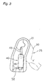
- the bail arm 25 may be positioned in the line winding position for guiding the fishing line to the outer circumference of the spool 4 (see Fig. 2) and may be manually pivoted into the line releasing position for allowing the fishing line to be cast out or fed out from the spool 4 (see Fig. 3).
- the bail reversing mechanism 26 includes a first toggle spring mechanism 40 disposed within the first arm portion 21, a second toggle spring mechanism 41 (Fig. 5) disposed within the rotor 3, and a switching projection 42 formed on an outer surface of the annular recess 2c of the reel body 2.
- the switching projection 42 serves as a switching member in a manner described below.
- the first toggle spring mechanism 40 has a first rod 45 extending back and force along the first arm portion 21, a first sleeve-like member 46 into which a rear end portion of the first rod 45 is slidably inserted and a first spring 47 for biasing the first rod 45 in a front direction.
- the first rod 45 is bent at a front end portion 45a inwardly as shown in Fig. 4 and engaged is with a hole 30a formed in the first bail support member 30.
- a jaw portion 45b is formed in the first rod 45.
- the front end of the first spring 47 is in contact with the jaw portion 45b.
- the first sleeve-like member 46 is pivotally mounted on the first arm portion 21 about a swing center A shown in Fig. 2.
- a stop portion 21a is formed in the front end portion of the first arm portion 21.
- the thus constructed first toggle spring mechanism 40 may take a first position as shown in Fig. 2 and a second position as shown in Fig. 3.
- the first position corresponds to the line winding position of the bail arm 25 and the second position corresponds to the line releasing position of the bail arm 25.
- the second position of the first toggle spring mechanism 40 shown in Fig. 3 is such that the first toggle spring mechanism 40 cannot force bail arm 25 to pivot about the swing axis M.
- the second toggle spring mechanism 41 includes a return lever 50 pivotally mounted on a rear surface of a portion of the rotor 3 between the cylindrical portion 20 and the first arm portion 21.
- the return lever 50 pivots about a shaft that is generally parallel to the spool shaft 15.
- the second toggle spring mechanism 41 also includes a second rod 51 retained at one end to the return lever 50, a second sleeve-like member 52 within which the second rod 51 is received and which is pivotally mounted to one end to the rotor 3, and a second spring 53 which biasing the second rod 51 toward the return lever 50.
- the second rod 51 and the second spring 53 are moveable in a plane that is perpendicular to the spool shaft 15 and therefore parallel with a rotor rotational plane.
- a retainer cutaway 50a is formed in the return lever 50 which receives a rear end of the first sleeve-like member 46.
- the retainer cutaway 50a is larger that the portion of the first sleeve-like member 46 which extends into the retainer cutaway 50a. Therefore, when the return lever 50 moves with respect to the first sleeve-like member 46 or vis versa, the two components collide with one another making a collision sound. Thus, the collision sound indicates to an operator that the bail arm 25 has been switched over from one position to another position.
- the switching projection 42 formed in the annular recess 2c of the body 2a extends radially outwardly.
- the switching projection 42 may come into contact with the projection 50c of the return lever 50.
- the switching projection 42 smoothly collides with the projection 50c of the return lever 50 and has a curved shape so as to accelerate the smooth rotation of the return lever 50.
- the rotor brake mechanism 9 is a mechanism for braking the rotor 3 when the bail arm 25 is moved to the line releasing position.
- the rotor brake mechanism 9 includes the projection 50c of the above-described return lever 50, and a brake member 55 which is positioned to contact the projection 50c when the projection 50c is in the position indicated in solid lines in Fig. 7, specifically when the projection 50c is pointing generally radially inward toward the rotor rotational center axis when the bail arm 25 is in the line releasing position.
- the brake member 55 is made of an elastic material such as, for example, NBR, silicone rubber.
- the brake member 55 is mounted on the wall surface 2d of the annular recess 2c of the body 2a and is disposed substantially in the form of a ring along the rotor rotational direction except the portion where the switching projection 42 of the wall surface 2d is formed.
- the cross-section of the brake member 55 is, for example, in the form of a semicircular shape and is elastically deformed by the contact with the projection 50c when the bail arm 25 is positioned in the line releasing position.
- the brake member 55 is provided in the ring substantially along the rotor rotational direction so that, even if the rotor 3 is stopped at any rotational phase, when the bail arm 25 is reversed to the line releasing position, the rotor 3 is always braked.
- the bail arm 25 When the fishing line is to be wound around the spool 4, the bail arm 25 is brought into the line winding position under the condition that the reverse rotation preventing mechanism 7 is brought into the reverse rotation preventing position by the operating lever 8 to thereby prevent the reverse rotation of the rotor 3.
- the first bail support member 30 and the second bail support member 32 are in the upright state on the front side as shown in Figs. 1 and 2.
- the first toggle spring mechanism 40 Under this condition, in the first toggle spring mechanism 40, the first sleeve-like member 46 is swung clockwise by the first spring 47 as shown in Fig. 2, and the first rod 45 is in the advanced condition.
- the return lever 50 is positioned in the first position shown by two-dotted and dash lines in Fig.
- the first bail support member 30 and the second bail support member 32 are tilted rearwardly to take the line releasing position as shown in Fig. 3.
- the first toggle spring mechanism 40 the first rod 45 is rotated counterclockwise in Fig. 3 by the rotation of the first bail support member 30 and is located at the second position.
- the first sleeve-like member 46 is swung counterclockwise about the swing center A.
- the return lever 50 is swung clockwise in Fig. 5 in accordance with the swing motion of the first sleeve-like member 46 and is located in the second position indicated by the solid line. In this condition, the return lever 50 is retained in position by the second rod 51 and the second spring 53.
- the first rod 45 is substantially at a dead point (where its biasing force in inoperable) so that movement to the first position (Fig. 2) is effected only by applying a little force in addition to the force from the second toggle spring mechanism 41.
- the second toggle spring mechanism 41 is structured so that its position is switched by the return lever 50 rotating within the rotor rotational plane, the force of the rotor rotation is effectively transmitted to the return lever 50 without any reduction. Accordingly, upon the operation of the handle, it is possible to switch the bail from the line releasing position to the line winding position with a small amont of force.
- the projection 50c comes into contact with the brake member 55 and the rotor 3 is braked by the frictional force so that the rotational position may be maintained. Accordingly, there is no possibility that the rotor 3 is rotated when the bail arm 25 is brought into the line releasing position. Accordingly, it is possible to overcome the defects due to an accidental rotation of the rotor 3 upon the casting or thumbing. In addition, since the rotor 3 is braked only by the friction, if the force is applied to the rotor 3, it is possible to readily rotate it and to adjust the rotational phase.
- a linear groove 2e is provided between the switching projection 42a and the other portion in the annular recess 2c.
- a brake member 55a is mounted such that the brake member 55a defines a D-shaped ring so as to pass through the groove 2e.
- the brake member 55a extends through a generally straight portion of the groove 2e that is located on an inner circumferential side of a switching projection 42a. Further, in the generally straight portion of the groove 2e, the brake member 55a is disposed radially inward from a position contactable by the projection 50c.
- the projection 50c is positioned as shown in solid lines in Fig. 9, where the bail arm is in a line releasing position, and further the projection 50c located in the vicinity of the projection 42a, the projection 50c is spaced apart from the braking member 55a.
- the brake member 55a is endless in the Second Embodiment, it is possible to use an elastic member available on the market such as an O-ring. Also, when the rotor 3 is rotated under the condition that the bail arm 25 is kept in the line releasing position, since the projection 50c is separated away from the brake member 55a in the vicinity of the switcning projection 42a so that the brake is released, the rotation of the rotor 3 is light and the second toggle spring mechanism 41 may readily be moved from the second position to the first position.
- a D-shaped groove for mounting the O-ring may be formed in the wall surface 2d and the O-ring may be fixed by a suitable fixing means such as an adhesive.
- the first bail support member 30' is pivotally mounted outside of the first arm portion 21.
- the first rod 45 of the first toggle spring mechanism 40 of the bail reversing mechanism 26 is bent at its tip end radially outwardly and is engaged with the first bail support member 30'.
- the other structure of the first toggle spring mechanism 40 is the same as that of the above-described First Embodiment.
- the second toggle spring mechanism 41 has a return lever 50', a second sleeve-like member 51a retained to the return lever 50' at one end, a second rod 52a which is received at one end in the second sleeve-like member 51a and pivotally mounted at the other end to the rotor 3, and a second spring 53 for biasing the second sleeve-like member 51a on the side of the return lever 50'.
- the return lever 50' is pivotally mounted within a plane in parallel with the rotor rotational plane to a rear surface of the joint portion between the cylindrical portion 20 of the rotor 3 and the first arm portion 21.
- the return lever 50' has a retainer cutaway 50a' for retaining the rear end of the first sleeve-like member 46 of the first toggle spring mechanism 40, a hole 50b for retaining the second sleeve-like member, and a projection 50c that extends toward the rotor rotational center axis.
- a gap is defined between the surfaces of the retainer cutaway 50a and the rear portion of the first sleeve-like member 46 to allow for a collision sound to be produced upon relative movement therebetween.
- a brake member 55b is composed of the O-ring, and is mounted on a bottom portion of the annular recess 2c unlike the above-described two embodiments. For this reason, as shown in Fig. 12, the tip end portion of the projection 50c is brought into contact with the outer circumferential portion of the brake member 55b rather than the side portion thereof. As shown in Fig. 11, the tip end portion of the projection 50c is formed into an arcuate shape about the swing center of the return lever 50.
- the projection 50c is thus formed on the arcuate shape, so that, even if the return lever 50 is swung to some extent by the displacement when the rotor 3 is rotated upon the braking, the projection 50c always enters by the same amount from the outer circumferential side into the brake member 55. Thus, the contact condition hardly changes. For this reason, even if the rotor 3 is manually rotated, the brake force hardly changes so that a stable brake force can be obtained.
- the return lever 50' may take the first position indicated by the two-dot and dash line and the second position indicated by the solid line in Fig. 11 with the second sleeve-like member 51a and the second spring 53 applying force to assist in the toggling thereof.
- the first position corresponds to the first position of the first toggle spring mechanism 40 and the line winding position of the bail arm 25, and the second position corresponds to the second position of the first toggle spring mechanism 40 and the line releasing position of the bail arm 25.
- the switching projection 42b is formed in the wall portion of the annular recess 2c of the body 2a on the outer circumferential side of the brake member 55b and the brake member 55b may be arranged substantially in an annular shape.
- An operating shaft 8a of the operating lever 8 is cut away into a triangular shape at a position where the brake member 55b passes as shown in Fig. 11 in order to avoid the brake member 55b composed of the O-ring.
- the rotor if the bail arm is brought in the line releasing position, the rotor is braked. Accordingly, there is no fear that the rotor is rotated accidentally. In addition, since the rotor is braked but is not locked, it is possible to readily rotate the rotor manually using extra force to overcome the braking. For this reason, if the rotor is once set at an optimum rotational phase upon casting or thumbing, it is possible to maintain its phase and also to readily rotate the rotor from the set phase to another phase, and thus the rotational phase (or position) of the rotor can be adjusted as desired.
Landscapes
- Life Sciences & Earth Sciences (AREA)
- Environmental Sciences (AREA)
- Animal Husbandry (AREA)
- Biodiversity & Conservation Biology (AREA)
Description
- The present invention relates to a spinning reel according to
claim 1. - In general, a spinning reel has a reel body, a rotor rotatably supported to a reel body and a spool around which a fishing line is to be wound. The rotor has first and second arm portions disposed to face each other so as to clamp a rotary shaft, and a bail arm pivotally mounted at tip ends of the two arms.
- The bail arm has a pair of bail support members pivotally mounted on the first and second arm portions, respectively, a fishing line guide portion including a line roller mounted at a tip end of one of the bail support members, and a bail disposed between the fishing line guide portion and the other bail support member. The bail arm may be positioned in a line winding position for winding fishing line around the outer circumference of the spool and the bail arm may be pivoted to a line releasing position where the bail arm is tilted from the line winding position so as not to be an obstruction when the fishing line is fed out or cast out from the spool.
- Also, a bail reversing device is provided on the rotor for maintaining the bail at the line winding position and at the line releasing position and for reversing the bail between the two positions. The bail reversing device has a return mechanism for automatically returning the bail back to the line winding position when the rotor is rotated by the handle while the bail is being kept in the line releasing position.
- Also, the spinning reel has a reverse rotation preventing mechanism for preventing the rotor from rotating in a reverse direction (in the rotation in the line feeding direction). When the reverse rotation preventing mechanism operates, the rotor is prevented from rotating in the reverse direction (a direction opposite the direction of rotation for winding line about the spool).
- In such a spinning reel, when the fishing line is fed out by, for instance, casting, after the fishing line is hooked by a palm side of an index finger under the condition that the reverse rotation of the rotor is prevented, the bail arm is reversed to the line releasing position. The rotor is rotated so that the line roller comes to the fishing rod side so as to readily hook the fishing line. Then, the fishing rod is swung down and the fishing line is released from the index finger in the midway for waiting for fishing device to reach the water surface. After the fishing device has reached the water surface, when the fishing device sinks to some extent, the handle is rotated and the bail arm is returned back to the line winding position by the return mechanism of the bail reversing device.
- Also, when the fishing line is fed by a pull from the fishing device after casting or on the fishing boat, after the bail arm is reversed to the line releasing position, a so-called finger braking operation for pressing the tip end of the spool by the tip end portion of the finger and contacting the palm side of the finger to the fishing line to prevent the fishing line from being loosened is performed. In this case, the rotor is rotated to a position where the bail support members constitutes an obstacle.
- In the above-described conventional spinning reel, when the bail arm is kept in the line releasing position, if the reverse rotation is prevented by the reverse rotation preventing mechanism, there is no possibility that the rotor is rotated in the line feeding direction. However, there is a possibility that the rotor is rotated in the line winding direction. In recent spinning reel models, the rotor is of a very light material and is readily rotatable because the rotational balance is enhanced in order to obtain a high winding efficiency. For this reason, in the spinning reel whose rotational balance is enhanced, the rotor is likely to be rotated with ease in the line winding direction. When the rotor is rotated, even if the rotor is rotated at the rotational phase suitable for the casting or thumbing, the rotational phase of the rotor is readily displaced.
- In order to avoid this, there is a prior art in which, when the bail arm is reversed to the line releasing position, the rotation of the rotor is locked. However, if the rotation of the rotor is locked, the readjustment of the rotational phase-or position of the rotor relative to the reel housing is impossible. For this reason, whenever the rotational phase need to be modified to change the position of the bail support members for the casting and for thumbing, it is necessary to return each time the bail arm back to the line winding position to readjust the rotational phase.
- The present invention is directed to making it possible to maintain, in a spinning reel, the rotational phase of the rotor with respect to the reel housing and to adjust the rotational position of the rotor when the bail arm is in the line releasing position.
- In accordance with a first aspect of the present invention, a rotor brake mechanism for a spinning reel includes a reel body and a rotor supported on the reel body for rotation in response to rotation of a handle which extends from the reel body. A bail arm is supported on the rotor, the bail arm being configured to pivot about a pivot axis defined on a portion of the rotor between a line winding position and a line releasing position. A brake member made of an elastic material has a ring shape and is disposed in a groove formed in the reel body adjacent to a portion of the rotor. A moving mechanism is supported within a portion of the rotor, the moving mechanism being configured to respond to movement of the bail arm such that a portion of the moving mechanism engages the braking member with the bail arm in the line releasing position.
- In the above rotor brake mechanism, when the bail is swung from the line winding position to the line releasing position, the moving mechanism is moved in cooperation with the pivoting motion and is brought into contact with the brake member to thereby brake the rotor. For this reason, when the bail arm takes the line releasing position, the rotor is braked and the rotor never rotates accidentally. In addition, since the moving mechanism is brought into contact with the brake member made of an elastic material to thereby brake the rotor but does not lock the rotor, it is possible to readily rotate the rotor if the rotor is manually rotated. For this reason, once the rotor is set at a suitable rotational phase upon casting or thumbing, it is possible to keep the phase and it is possible to readily rotate the rotor from the set phase to another phase. It is also possible to adjust the rotational phase of the rotor as desired.
- Preferably, the moving mechanism includes a lever member pivotally mounted on the rotor for pivotal movement between a first position and a second position such that in the second position a portion of the lever member contacts the brake member and in the first position the lever member is spaced apart from the brake member. As well, the moving mechanism further includes a cooperating mechanism for swinging the lever member toward the second position in cooperation with swing motion of the bail arm when the bail arm is swung from the line winding position to the line releasing position.
- Preferably, a tip end portion of the lever member is configured for contact with the brake member and is formed with an arcuate shape with respect to a pivot axis about which the lever member pivots.
- Preferably, a bail reversing mechanism is at least partially supported in the rotor. The reversing mechanism is configured to pivot the bail arm from the line releasing position to the line winding position in response to rotation of the rotor with respect to the reel body. The cooperating mechanism at least partially defines a portion of the bail reversing mechanism, and the moving mechanism is configured to maintain the bail arm in the line winding position and in the line releasing position.
- In accordance with a second aspect of the present invention, a spinning reel is mountable on a fishing rod for winding a fishing line by rotation of a handle. The spinning reel includes a reel body having a handle, the reel body being mountable on a fishing rod. A rotor having a first arm portion and a second arm portion disposed on opposite circumferential sides of the rotor facing each other, is supported rotatably to a front portion of the reel body. A bail arm is supported at tip ends of the first and second arm portions, the bail arm being pivotable about an axis extending between the tip ends of the first and second arm portions. The bail arm is pivotal between a line winding position and a line releasing position. A spool is supported on the reel body proximate a front portion of the rotor for winding the fishing line. Further, there is a rotor brake mechanism for braking the rotor when the bail arm is positioned in the line releasing position.
- Preferably, the rotor further includes a bail reversing mechanism for maintaining the bail arm in the line winding position and the line releasing position and for moving the bail arm from the line releasing position to the line winding position in response to rotation of the rotor with respect to the reel body.
- Preferably, the bail arm has a first bail support member and a second bail support member pivotally mounted at the tip ends of the first and second arm portions and a bail extending between the first and second bail support members. The bail reversing mechanism includes a toggle mechanism which maintains position of the bail arm where the bail arm is in one of the line winding position and the line releasing position. The bail reversing mechanism further includes a protrusion formed on the reel body so as to be contactable with a portion of the toggle mechanism with the bail arm in the line releasing position such that in response to contact with the protrusion the toggle mechanism urges the bail arm from the line releasing position toward the line winding position. The rotor brake mechanism is defined by a portion of the toggle mechanism and the rotor brake mechanism is further defined by a brake member disposed on the reel body. The brake member is contactable with a portion of the toggle mechanism for braking the rotor with the bail arm in the line releasing position.
- In accordance with a third aspect of the present invention, a spinning reel includes a reel body mountable on a fishing rod and a rotor formed with a first arm portion and a second arm portion disposed to face each other on opposite circumferential sides thereof. A, bail arm extends between tip ends of the first and second arm portions. The bail arm is reversible between a line winding position and a line releasing position. The rotor is supported on a portion of the reel body. A bail reversing mechanism is disposed at least partially in the rotor for maintaining the bail arm in the line winding position and the line releasing position and for reversing the bail arm from the line releasing position to the line winding position in response to rotation of the rotor on the reel body. A spool is supported on the reel body proximate a front portion of the rotor for winding a fishing line. Further, the spinning reel includes a rotor brake mechanism for braking the rotor when the bail arm is positioned in the line releasing position.
- Preferably, the bail arm has a first bail support member and a second bail support member pivotally mounted at the tip ends of the first and second arm portions and a bail extending between the first and second bail support members. The bail reversing mechanism includes a toggle mechanism which maintains position of the bail arm where the bail arm is in one of the line winding position and the line releasing position. The bail reversing mechanism further includes a protrusion formed on the reel body so as to be contactable with a return lever of the toggle mechanism with the bail arm in the line releasing position such that in response to contact between the protrusion and the return lever. The toggle mechanism urges the bail arm from the line releasing position toward the line winding position. The rotor brake mechanism is defined by the return lever of the toggle mechanism and by a brake member disposed on the reel body, the brake member being contactable with the return lever of the toggle mechanism for braking the rotor with the bail arm in the line releasing position.
- Preferably, the brake member is made of an elastic material and disposed substantially in the shape of a ring along a portion of the reel body proximate a portion of the rotor.
- Preferably, the brake member is disposed in the reel body such that the brake member is not contactable with the return lever of the toggle mechanism with the toggle mechanism being circumferentially positioned proximate the protrusion.
- Preferably, the toggle mechanism includes a first toggle spring mechanism disposed in the first arm portion for biasing the toggle mechanism into one of a first position and a second position, the first position corresponding to the bail arm being in the line winding position and the second position corresponding to the bail arm being in the line releasing position. The toggle mechanism also includes a second toggle spring mechanism which is disposed on the rotor and engaged with the return lever of the toggle mechanism for biasing the return lever into one of the first position and the second position.
- Preferably, the first toggle spring mechanism includes: a first rod having a first end retained in a portion of the first bail support member, the first rod extending along the first arm portion; a first sleeve-like member into which a second end of the first rod is slidably inserted, the first sleeve-like member being mounted in the first arm portion and being pivotal about a mid-portion thereof with respect to the first arm portion within the first arm portion of the rotor; and a first spring inserted into an interior of the first sleeve-like member for biasing the first rod toward the first bail support member. The return lever is engageable with a portion of the first sleeve-like member. The second toggle spring mechanism includes: a second rod having one end retained in a portion of the return lever, a second sleeve-like member in which the second rod is received and which is pivotally mounted on the rotor, and a second spring for biasing the second rod toward the return lever.
- Alternatively, the first toggle spring mechanism includes: a first rod having a first end retained in a portion of the first bail support member, the first rod extending along the first arm portion; a first sleeve-like member into which a second end of the first rod is slidably inserted, the first sleeve-like member being mounted in the first arm portion and being pivotal about a mid-portion thereof with respect to the first arm portion within the first arm portion of the rotor; and a first spring inserted into an interior of the first sleeve-like member for biasing the first rod toward the first bail support member. The return lever is engageable with a portion of the first sleeve-like member. The second toggle spring mechanism includes: a second rod having one end retained in a portion of the rotor, a second sleeve-like member in which the second rod is received and which is pivotally mounted on the a portion of the return lever, and a second spring disposed between the second rod and the second sleeve-like member for biasing the second sleeve-like member toward the return lever.
- Preferably, a contact portion of the return lever is configured to contact the brake member and said contact portion is formed with an arcuate shape.
- In the above spinning reel, the bail arm is reversed to the line releasing position upon casting or thumbing. Also, when the feeding of the fishing line is stopped or the fishing line is wound, the bail arm is returned back to the line winding position. When it is reversed to the line winding position and the rotor is rotated, the fishing line is guided by and wound around the spool. On the other, when the bail arm is in the line releasing position, the rotor is braked by the rotor brake mechanism. Accordingly, there is no fear that the rotor is rotated accidentally. In addition, since the brake mechanism just brakes the rotor but does not lock the rotor, it is possible to readily rotate the rotor if the rotor is manually rotated. For this reason, once the rotor is set at a suitable rotational phase upon casting or thumbing, it is possible to keep the phase and it is possible to readily rotate the rotor from the set phase to another phase. It is also possible to adjust the rotational phase of the rotor as desired.
- As well, in the above configurations of the present invention, the return lever is a part of a bail reversing mechanism and is also part a rotor braking mechanism thus reducing the number of moving parts and simplifying manufacturing costs.
- The rotor brake mechanism just brakes the rotor but does not lock the rotor in place, since with additional force it is still possible to rotate the rotor against the braking force. For this reason, once the rotor is set at a suitable rotational phase upon casting or thumbing, it is possible to keep the phase and to readily rotate the rotor from the set phase to another phase. It is also possible to adjust the rotational phase of the rotor as desired.
- These and other objects, features, aspects and advantages of the present invention will become more fully apparent from the following detailed description of the present invention when taken in conjunction with the accompanying drawings where like reference numerals denote corresponding parts throughout.
-
- Fig. 1 is a cross-section side view of a spinning reel having a spool, a rotor and a bail in accordance with a first embodiment of the present invention;
- Fig. 2 is a fragmentary, part cross-section view of an interior of a first arm portion which supports the bail of the spinning reel depicted in Fig. 1 with the first arm portion in a position corresponding to the bail being in a line winding position;
- Fig. 3 is a fragmentary view similar to Fig. 2, showing the interior of a first arm portion which supports the bail of the spinning reel depicted in Fig. 1 with the first arm portion in a position corresponding to the bail being in a line releasing position;
- Fig. 4 is a fragmentary, part cross-section view of a first toggle spring mechanism associated with the first arm portion;
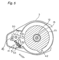
- Fig. 5 is a fragmentary, part cross-section bottom view of the rotor showing details of a second toggle mechanism taken along the line V-V in Fig. 1;
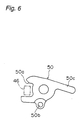
- Fig. 6 is an enlarged view of a lever of the second toggle spring mechanism depicted in Fig. 5;
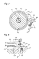
- Fig. 7 is a cross-sectional view taken along the line VII-VII in Fig. 1;
- Fig. 8 is an enlarged view of a rotor brake mechanism;
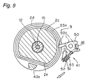
- Fig. 9 is a part elevation, part cross-section view, similar to Fig. 7, showing a rotor and toggle spring mechanism in accordance with a second embodiment;
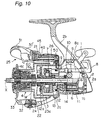
- Fig. 10 is a cross-section side view similar to Fig. 1, showing a spinning reel having a spool, a rotor and a bail in accordance with a third embodiment of the present invention;
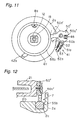
- Fig. 11 is part cross-section view similar to Fig. 7 showing details of a toggle mechanism in accordance with the third embodiment of the present invention;
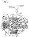
- Fig. 12 is a cross-section view similar to Fig. 8 showing further details of the third embodiment; and
- Fig. 13 is a side cross-section view similar to Fig. 1 showing details of a fourth embodiment.
-
- A spinning reel in accordance with a First Embodiment of the present invention is shown in Fig. 1 and is provided with a
reel body 2 having ahandle 1, arotor 3 rotatably supported on a front portion of thereel body 2, and aspool 4 disposed in the front portion of therotor 3 for winding the fishing line. - The
reel body 2 has abody 2a having an upper portion on which a mountingportion 2b is formed for mounting the spinning reel on the fishing rod. Anannular recess 2c is formed in the front portion of thebody 2a. Also, in the interior of thebody 2a, there are provided arotor drive mechanism 5 for rotating therotor 3, anoscillating mechanism 6 for moving thespool 4 back and forth along a rotational center axis X to uniformly wind the fishing line on thespool 4, a reverserotation preventing mechanism 7 for preventing the reverse rotation of the rotor 3 (the rotation in the line feeding direction), and arotor brake mechanism 9 for braking the rotation of therotor 3. - The
rotor drive mechanism 5 has aface gear 11 rotating together with ashaft 10 to which thehandle 1 is fixed, and apinion gear 12 engaged with theface gear 11. Thepinion gear 12 is formed into a sleeve and afront portion 12a extends toward thespool 4 through a central portion of therotor 3. A screw portion is formed at a distal end of thepinion gear 12. In such an arrangement, theface gear 11 and thepinion gear 12 are rotated by the handle, and therotor 3 fixed to thepinion gear 12 is also rotated. - In the reverse
rotation preventing mechanism 7, a roller type one-way clutch is used and consequently idle rotation of therotor 3 upon the reverse rotation is thereby limited. The reverserotation preventing mechanism 7 may be selectively engaged and dis-engaged by means of an operatinglever 8 which may be moved from a reverse rotation preventing position and to a reverse rotation allowing position. The operatinglever 8 is pivotally mounted on a rear portion of thebody 2a. An operating shaft 8a fixed to the operatinglever 8 extends to the reverserotation preventing mechanism 7. - The
rotor 3 has acylindrical portion 20, afirst arm portion 21 and asecond arm portion 22 which are formed to face each other on opposite sides of thecylindrical portion 20, abail arm 25 which extends between the twoarm portions bail arm 25 may be pivoted about an axis M defined between the twoarm portions rotor 3 also includes abail reversing mechanism 26 which is configured to move thebail arm 25 to the line winding position from the line releasing position in a manner described below. Thecylindrical portion 20 and the twoarm portions - A
front wall 23 is formed at the front portion of thecylindrical portion 20. Aboss 23a is formed in the central portion of thefront wall 23. A through-hole is formed in the central portion of theboss 23a. Thefront portion 12a of thepinion gear 12 and thespool shaft 15 pass through the through-hole. Anut 24 is disposed on the front side of thefront wall 23. Thenut 24 is engaged with a screw portion at a front end of thepinion gear 12. A bearing for rotatably supporting thespool shaft 15 is disposed in the inner circumferential portion of thenut 24. - The
bail arm 25 includes a firstbail support member 30 and a secondbail support member 32 which are pivotally mounted on the inner circumferential sides at tip ends of the first andsecond arm portions bail arm 25 also includes aline roller 31 and thebail 33. Theline roller 31 serves to guide the fishing line to thespool 4 and is mounted rotatably at the tip end of the firstbail support member 30. Thebail 33 extends between theline roller 31 at the tip end of the firstbail support member 30 and the secondbail support member 32. - As mentioned above, the
bail arm 25 is configured to be swung about the swing axis M which is not perpendicular to the rotational center axis X but rather is slanted at a predetermined angle. Thebail arm 25 may be positioned in the line winding position for guiding the fishing line to the outer circumference of the spool 4 (see Fig. 2) and may be manually pivoted into the line releasing position for allowing the fishing line to be cast out or fed out from the spool 4 (see Fig. 3). - The
bail reversing mechanism 26 will now be described. - As shown in Figs. 2 to 5, the
bail reversing mechanism 26 includes a firsttoggle spring mechanism 40 disposed within thefirst arm portion 21, a second toggle spring mechanism 41 (Fig. 5) disposed within therotor 3, and a switchingprojection 42 formed on an outer surface of theannular recess 2c of thereel body 2. The switchingprojection 42 serves as a switching member in a manner described below. - The first
toggle spring mechanism 40 has afirst rod 45 extending back and force along thefirst arm portion 21, a first sleeve-like member 46 into which a rear end portion of thefirst rod 45 is slidably inserted and afirst spring 47 for biasing thefirst rod 45 in a front direction. Thefirst rod 45 is bent at afront end portion 45a inwardly as shown in Fig. 4 and engaged is with a hole 30a formed in the firstbail support member 30. Also, ajaw portion 45b is formed in thefirst rod 45. The front end of thefirst spring 47 is in contact with thejaw portion 45b. The first sleeve-like member 46 is pivotally mounted on thefirst arm portion 21 about a swing center A shown in Fig. 2. On the other hand, astop portion 21a is formed in the front end portion of thefirst arm portion 21. - The thus constructed first
toggle spring mechanism 40 may take a first position as shown in Fig. 2 and a second position as shown in Fig. 3. The first position corresponds to the line winding position of thebail arm 25 and the second position corresponds to the line releasing position of thebail arm 25. Also, the second position of the firsttoggle spring mechanism 40 shown in Fig. 3 is such that the firsttoggle spring mechanism 40 cannot forcebail arm 25 to pivot about the swing axis M. - The second
toggle spring mechanism 41 includes areturn lever 50 pivotally mounted on a rear surface of a portion of therotor 3 between thecylindrical portion 20 and thefirst arm portion 21. Thereturn lever 50 pivots about a shaft that is generally parallel to thespool shaft 15. The secondtoggle spring mechanism 41 also includes asecond rod 51 retained at one end to thereturn lever 50, a second sleeve-like member 52 within which thesecond rod 51 is received and which is pivotally mounted to one end to therotor 3, and asecond spring 53 which biasing thesecond rod 51 toward thereturn lever 50. Incidentally, thesecond rod 51 and thesecond spring 53 are moveable in a plane that is perpendicular to thespool shaft 15 and therefore parallel with a rotor rotational plane. - A
retainer cutaway 50a is formed in thereturn lever 50 which receives a rear end of the first sleeve-like member 46. As can be seen in Figs. 5, 6 and 7, theretainer cutaway 50a is larger that the portion of the first sleeve-like member 46 which extends into theretainer cutaway 50a. Therefore, when thereturn lever 50 moves with respect to the first sleeve-like member 46 or vis versa, the two components collide with one another making a collision sound. Thus, the collision sound indicates to an operator that thebail arm 25 has been switched over from one position to another position. - As shown in Fig. 5, the switching
projection 42 formed in theannular recess 2c of thebody 2a extends radially outwardly. When thereturn lever 50 of the secondtoggle spring mechanism 41 is rotated together with therotor 3, the switchingprojection 42 may come into contact with theprojection 50c of thereturn lever 50. The switchingprojection 42 smoothly collides with theprojection 50c of thereturn lever 50 and has a curved shape so as to accelerate the smooth rotation of thereturn lever 50. - Referring again to Fig. 1, the
rotor brake mechanism 9 is a mechanism for braking therotor 3 when thebail arm 25 is moved to the line releasing position. As shown in Figs. 7 and 8, therotor brake mechanism 9 includes theprojection 50c of the above-describedreturn lever 50, and abrake member 55 which is positioned to contact theprojection 50c when theprojection 50c is in the position indicated in solid lines in Fig. 7, specifically when theprojection 50c is pointing generally radially inward toward the rotor rotational center axis when thebail arm 25 is in the line releasing position. Thebrake member 55 is made of an elastic material such as, for example, NBR, silicone rubber. Thebrake member 55 is mounted on thewall surface 2d of theannular recess 2c of thebody 2a and is disposed substantially in the form of a ring along the rotor rotational direction except the portion where the switchingprojection 42 of thewall surface 2d is formed. The cross-section of thebrake member 55 is, for example, in the form of a semicircular shape and is elastically deformed by the contact with theprojection 50c when thebail arm 25 is positioned in the line releasing position. Here, thebrake member 55 is provided in the ring substantially along the rotor rotational direction so that, even if therotor 3 is stopped at any rotational phase, when thebail arm 25 is reversed to the line releasing position, therotor 3 is always braked. - The bail reversing operation will now be described.
- When the fishing line is to be wound around the
spool 4, thebail arm 25 is brought into the line winding position under the condition that the reverserotation preventing mechanism 7 is brought into the reverse rotation preventing position by the operatinglever 8 to thereby prevent the reverse rotation of therotor 3. In this case, the firstbail support member 30 and the secondbail support member 32 are in the upright state on the front side as shown in Figs. 1 and 2. Under this condition, in the firsttoggle spring mechanism 40, the first sleeve-like member 46 is swung clockwise by thefirst spring 47 as shown in Fig. 2, and thefirst rod 45 is in the advanced condition. Also, in the secondtoggle spring mechanism 41, thereturn lever 50 is positioned in the first position shown by two-dotted and dash lines in Fig. 5, and this condition is maintained by thesecond rod 51 due to the biasing force of thesecond spring 53. Incidentally, in this condition, theprojection 50c of thereturn lever 50 is retracted on the outer circumferential side of the rotor, and there is no fear that theprojection 50c would come into contact with the switchingprojection 42 as therotor 3 rotates. - When the
bail arm 25 is tilted from this condition, the firstbail support member 30 and the secondbail support member 32 are tilted rearwardly to take the line releasing position as shown in Fig. 3. In the condition that thebail arm 25 is tilted in the line releasing position, it is possible to readily feed the fishing line from thespool 4. Under this condition, in the firsttoggle spring mechanism 40, thefirst rod 45 is rotated counterclockwise in Fig. 3 by the rotation of the firstbail support member 30 and is located at the second position. According to this, the first sleeve-like member 46 is swung counterclockwise about the swing center A. In the secondtoggle spring mechanism 41, thereturn lever 50 is swung clockwise in Fig. 5 in accordance with the swing motion of the first sleeve-like member 46 and is located in the second position indicated by the solid line. In this condition, thereturn lever 50 is retained in position by thesecond rod 51 and thesecond spring 53. - When the
return lever 50 is swung to the second position, as shown in Figs. 7 and 8, theprojection 50c of thereturn lever 50 extends toward the rotor rotational center axis and comes into elastic contact with thebrake member 55. As a result, therotor 3 is braked so that its rotational movement is restrained. However, sincereturn lever 50 on therotor 3 simply contacts elastically with thebrake member 55 and is braked by the friction contact therewith, it is possible to adjust the rotational position by forceably rotating therotor 3 manually or by applying extra rotating force on thehandle 1. - If the
rotor 3 is rotated in the line winding direction by thehandle 1 operation while keeping thebail arm 25 in the line releasing position, in Fig. 5, thereturn lever 50 of the secondtoggle spring mechanism 41 is rotated counterclockwise as indicated by a blank arrow in Fig. 7 together with therotor 3. Then, theprojection 50c of thereturn lever 50 collides against the switchingprojection 42 fixed on the side of thereel body 2. Thus, thereturn lever 50 is kicked up to be switched over to the first position indicated by the two-dot and dash line. As a result, the first sleeve-like member 46 of the firsttoggle spring mechanism 40 is switched over to the first position shown in Fig. 2 from the second position shown in Fig. 3, and the firstbail support member 30 and the secondbail support member 32 are switched over to the line winding position assisted by the biasing force of thefirst spring 47. - At this time with the first
toggle spring mechanism 40 in the second position (Fig. 3), thefirst rod 45 is substantially at a dead point (where its biasing force in inoperable) so that movement to the first position (Fig. 2) is effected only by applying a little force in addition to the force from the secondtoggle spring mechanism 41. Also, since the secondtoggle spring mechanism 41 is structured so that its position is switched by thereturn lever 50 rotating within the rotor rotational plane, the force of the rotor rotation is effectively transmitted to thereturn lever 50 without any reduction. Accordingly, upon the operation of the handle, it is possible to switch the bail from the line releasing position to the line winding position with a small amont of force. - Also, if the
bail arm 25 is in the line releasing position, theprojection 50c comes into contact with thebrake member 55 and therotor 3 is braked by the frictional force so that the rotational position may be maintained. Accordingly, there is no possibility that therotor 3 is rotated when thebail arm 25 is brought into the line releasing position. Accordingly, it is possible to overcome the defects due to an accidental rotation of therotor 3 upon the casting or thumbing. In addition, since therotor 3 is braked only by the friction, if the force is applied to therotor 3, it is possible to readily rotate it and to adjust the rotational phase. - In a Second Embodiment, most elements and structures are the same as in the First Embodiment described above. Therefore, only those portions, features and functions which differ from the First Embodiment will be described in detail. As shown in Fig. 9, a
linear groove 2e is provided between the switchingprojection 42a and the other portion in theannular recess 2c. Abrake member 55a is mounted such that thebrake member 55a defines a D-shaped ring so as to pass through thegroove 2e. Thebrake member 55a extends through a generally straight portion of thegroove 2e that is located on an inner circumferential side of a switchingprojection 42a. Further, in the generally straight portion of thegroove 2e, thebrake member 55a is disposed radially inward from a position contactable by theprojection 50c. For this reason, if theprojection 50c is positioned as shown in solid lines in Fig. 9, where the bail arm is in a line releasing position, and further theprojection 50c located in the vicinity of theprojection 42a, theprojection 50c is spaced apart from the brakingmember 55a. - Since the
brake member 55a is endless in the Second Embodiment, it is possible to use an elastic member available on the market such as an O-ring. Also, when therotor 3 is rotated under the condition that thebail arm 25 is kept in the line releasing position, since theprojection 50c is separated away from thebrake member 55a in the vicinity of theswitcning projection 42a so that the brake is released, the rotation of therotor 3 is light and the secondtoggle spring mechanism 41 may readily be moved from the second position to the first position. - Incidentally, in the case where the O-ring is used for the
brake member 55a, it is sufficient that a D-shaped groove for mounting the O-ring may be formed in thewall surface 2d and the O-ring may be fixed by a suitable fixing means such as an adhesive. - In a Third Embodiment, most elements and structures are the same as in the First Embodiment described above. Therefore, only those portions, features and functions wnich differ from the First Embodiment will be described in detail.
- As shown in Fig. 10, in a Third Embodiment, the first bail support member 30' is pivotally mounted outside of the
first arm portion 21. For this reason, thefirst rod 45 of the firsttoggle spring mechanism 40 of thebail reversing mechanism 26 is bent at its tip end radially outwardly and is engaged with the first bail support member 30'. The other structure of the firsttoggle spring mechanism 40 is the same as that of the above-described First Embodiment. - As shown in Figs. 11 and 12, the second
toggle spring mechanism 41 has a return lever 50', a second sleeve-like member 51a retained to the return lever 50' at one end, asecond rod 52a which is received at one end in the second sleeve-like member 51a and pivotally mounted at the other end to therotor 3, and asecond spring 53 for biasing the second sleeve-like member 51a on the side of the return lever 50'. The return lever 50' is pivotally mounted within a plane in parallel with the rotor rotational plane to a rear surface of the joint portion between thecylindrical portion 20 of therotor 3 and thefirst arm portion 21. - The above arrangement is different from that of the First Embodiment and the arrangements of the sleeve-like member and the rod are reversed. Incidentally, the second sleeve-
like member 51a and thesecond spring 53 are moved within the plane in parallel with the rotor rotational plane (the rotor rotational plane being perpendicular to the central axis of the spool shaft 15). - The return lever 50' has a
retainer cutaway 50a' for retaining the rear end of the first sleeve-like member 46 of the firsttoggle spring mechanism 40, ahole 50b for retaining the second sleeve-like member, and aprojection 50c that extends toward the rotor rotational center axis. A gap is defined between the surfaces of theretainer cutaway 50a and the rear portion of the first sleeve-like member 46 to allow for a collision sound to be produced upon relative movement therebetween. - Also, in the Third Embodiment, a
brake member 55b is composed of the O-ring, and is mounted on a bottom portion of theannular recess 2c unlike the above-described two embodiments. For this reason, as shown in Fig. 12, the tip end portion of theprojection 50c is brought into contact with the outer circumferential portion of thebrake member 55b rather than the side portion thereof. As shown in Fig. 11, the tip end portion of theprojection 50c is formed into an arcuate shape about the swing center of thereturn lever 50. Theprojection 50c is thus formed on the arcuate shape, so that, even if thereturn lever 50 is swung to some extent by the displacement when therotor 3 is rotated upon the braking, theprojection 50c always enters by the same amount from the outer circumferential side into thebrake member 55. Thus, the contact condition hardly changes. For this reason, even if therotor 3 is manually rotated, the brake force hardly changes so that a stable brake force can be obtained. - In the structure of such a second
toggle spring mechanism 41, the return lever 50' may take the first position indicated by the two-dot and dash line and the second position indicated by the solid line in Fig. 11 with the second sleeve-like member 51a and thesecond spring 53 applying force to assist in the toggling thereof. The first position corresponds to the first position of the firsttoggle spring mechanism 40 and the line winding position of thebail arm 25, and the second position corresponds to the second position of the firsttoggle spring mechanism 40 and the line releasing position of thebail arm 25. - The switching
projection 42b is formed in the wall portion of theannular recess 2c of thebody 2a on the outer circumferential side of thebrake member 55b and thebrake member 55b may be arranged substantially in an annular shape. - An operating shaft 8a of the operating
lever 8 is cut away into a triangular shape at a position where thebrake member 55b passes as shown in Fig. 11 in order to avoid thebrake member 55b composed of the O-ring. - The above embodiments may be further modified in a variety of ways and still remain within the scope of the invention. For example, the following modification may be made.
- (a) The arrangements of the bail reversing
mechanism and the rotor brake mechanism are not limited to
those of the above-described embodiments. It is possible
to provide the rotor brake mechanism separately from the
bail reversing mechanism. For instance, as shown in Fig.
13, a cooperating
mechanism 60 composed of a toggle spring mechanism and alever member 61 operated by the cooperatingmechanism 60 are provided on thesecond arm portion 22 of therotor 3. - (b) The O-ring is used as the brake member in the foregoing embodiments but the cross-section of the brake member is not limited to a circular shape like the O-ring.
- (c) The positional relationship between the
first rod 45 and the first sleeve-like member 46 in the firsttoggle spring mechanism 40 may be the opposite positional relationship as shown in the secondtoggle spring mechanism 41 of the third embodiment, i.e, the arrangement in which the first sleeve-like member 46 is engaged with the firstbail support member 30. - (d) The return lever is operated by the toggle spring mechanism in the foregoing embodiments. However, as disclosed in Japanese Utility Model Publication No. SHO 59-139069, it is possible to make the return lever as one example of the moving mechanism operate independently of the toggle spring mechanism. In this case, the operation mode of the return lever is not limited to the swing motion. It is possible to use any operational mode if it is structured that the return lever moves in cooperation of the swing motion of the bail arm as disclosed in the above-described publication.
-
- According to the present invention, if the bail arm is brought in the line releasing position, the rotor is braked. Accordingly, there is no fear that the rotor is rotated accidentally. In addition, since the rotor is braked but is not locked, it is possible to readily rotate the rotor manually using extra force to overcome the braking. For this reason, if the rotor is once set at an optimum rotational phase upon casting or thumbing, it is possible to maintain its phase and also to readily rotate the rotor from the set phase to another phase, and thus the rotational phase (or position) of the rotor can be adjusted as desired.
- The foregoing description of the embodiments according to the present invention is provided for the purpose of illustration only, and not for the purpose of limiting the invention as defined by the appended claims.
Claims (11)
- A spinning reel mountable on a fishing rod for winding a fishing line by rotation of a handle, the spinning reel comprising:characterised in that said reel further comprises:a reel body (2) having a handle (1), said reel body (2) being mountable on a fishing rod;a rotor (3) having a first arm portion (21) and a second arm portion (22) disposed on opposite circumferential sides of the rotor (3) facing each other, said rotor (3) being supported rotatably to a front portion of said reel body (2);a bail arm (25) supported at tip ends of said first and second arm portions (21,22), said bail arm (25) being pivotable about an axis (M) extending between said tip ends of said first and second arm portions (21,22), said bail arm (25) being pivotable between a line winding position and a line releasing position;a spool (4) supported on said reel body (2) proximate a front portion of said rotor (3) for winding the fishing line anda rotor brake mechanism (9) for braking said rotor (3) when said bail arm (25) is positioned in said line releasing position;a bail reversing mechanism (26) for urging said bail arm (25) in either said line winding position or said line releasing position and for moving said bail arm (25) from said line releasing position to said line winding position in response to rotation of said rotor (3) with respect to said reel body (2).
- A spinning reel as claimed in Claim 1, wherein said bail arm (25) has a first bail support member (30) and a second bail support member (32) pivotally mounted at said tip ends of said first and second arm portions (21,22) and a bail (33) extending between said first and second bail support members (30,32);said bail reversing mechanism (26) includes a toggle mechanism which maintains position of said bail arm (25) where said bail arm (25) is in one of said line winding position and said line releasing position, said bail reversing mechanism (26) further includes a protrusion(42)formed on said reel body (2) so as to be contactable with a portion of said toggle mechanism with said bail arm (25) in said line releasing position such that in response to contact with said protrusion (42) said toggle mechanism urges said bail arm (25) from said line releasing position toward said line winding position; andsaid rotor brake mechanism (9) is defined by a portion of said toggle mechanism and said rotor brake mechanism (9) is further defined by a brake member (55) disposed on said reel body (2), said brake member (55) being contactable with a portion of said toggle mechanism for braking said rotor (3) with said bail arm (25) in said line releasing position.
- A spinning reel as claimed in Claim 1, wherein said bail arm (25) has a first bail support member (30) and a second bail support member (32) pivotally mounted at said tip ends of said first and second arm portions (21,22) and a bail (31) extending between said first and second bail support members (30,32);said bail reversing mechanism (26) includes a toggle mechanism which urges said bail arm (25) in either said line winding position or said line releasing position, a return lever (50) movably mounted on said rotor (3) and cooperatively linked to said toggle mechanism and a protrusion(42)formed on said reel body (2) so as to be contactable with said return lever (50) with said bail arm (25) in said line releasing position such that in response to contact with said protrusion(42), said return lever (50) urges said bail arm (25) via said toggle mechanism from said line releasing position toward said line winding position; andsaid rotor brake mechanism (9) is defined by said return lever (50) and by a brake member (55)disposed on said reel body, said brake member (55) being contactable with said return lever (50) for braking said rotor (3) with said bail arm (25) in said line releasing position.
- A spinning reel as claimed in Claim 3, wherein said brake member (55) is made of an elastic material and disposed substantially in the shape of a ring along a portion of said reel body (2) proximate a portion of said rotor (3).
- A spinning reel as claimed in Claim 3 or Claim 4 wherein said brake member (55) is disposed in said reel body (2) such that the brake member (55) is not contactable with said return lever (50) of said toggle mechanism with said toggle mechanism being circumferentially positioned proximate said protrusion(42).
- A spinning reel as claimed in Claims 3 to 5 wherein said toggle mechanism comprises: a first toggle spring mechanism(40)disposed in said first arm portion (21) for biasing said toggle mechanism (40) into one of a first position and a second position, said first position corresponding to said bail arm (25) being in said line winding position and said second position corresponding to said bail arm (25) being in said line releasing position; and a second toggle spring mechanism(41)disposed on said rotor (3) and engaged with said return lever (50) of said toggle mechanism for biasing said return lever (50) into one of said first position and said second position.
- A spinning reel as claimed in Claim 6, wherein:said first toggle spring mechanism(40) comprises:a first rod (45) having a first end retained in a portion of said first bail support member (30), said first rod (45) extending along said first arm portion (21); a first sleeve-like member (46) into which a second end of said first rod (45) is slidably inserted, said first sleeve-like member (46) being mounted in said first arm portion (21) and being pivotal about a mid-portion (A) thereof with respect to said first arm portion (21) within said first arm portion (21) of said rotor (3); and a first spring (47) inserted into an interior of said first sleeve-like member (46) for biasing said first rod (45) toward said first bail support member (30);said return lever (50) is engageable with a portion of said first sleeve-like member (46); said second toggle spring mechanism (41) comprises: a second rod (51) having one end retained in a portion of said return lever (50), a second sleeve-like member (52) in which said second rod (51) is received and which is pivotally mounted on said rotor (3), and a second spring (53) for biasing said second rod (51) toward said return lever (50).
- A spinning reel as claimed in claim 6, wherein:said first toggle spring mechanism (40) comprises: a first rod (45) having a first end retained in a portion of said first bail support member (30), said first rod (45) extending along said first arm portion (21) ; a first sleeve-like member (46) into which a second end of said first rod (45) is slidably inserted, said first sleeve-like member (46) being mounted in said first arm portion (21) and being pivotal about a mid-portion (A) thereof with respect to said first arm portion (21) within said first arm portion (21) of said rotor (3); and a first spring (47) inserted into an interior of said first sleeve-like member (46) for biasing said first rod (45) toward said first bail support member (30); said return lever (50) is engageable with a portion of said first sleeve-like member (46); said second toggle spring mechanism (41) comprises: a second rod (51) having one end retained in a portion of said rotor (3), a second sleeve-like member (52) in which said second rod (51) is received and which is pivotally mounted on said portion of said return lever (50), and a second spring (53) disposed between said second rod (51) and said second sleeve-like member (52) for biasing said second sleeve-like member (50) toward said return lever (50).
- A spinning reel as claimed in any of Claims 3 to 8 wherein a contact portion (50c) of said return lever (50) is configured to contact said brake member (55) and said contact portion (50c) is formed with an arcuate shape about the swing centre of said lever (50).
- A spinning reel as claimed in any of Claims 3 to 9 wherein, upon braking, the return lever (50) is pivoted along a first direction into contact with said brake member (55) to deform said brake member (55) in a second direction substantially perpendicular to said first direction.
- The spinning reel as claimed in any preceding claim wherein said rotor braking mechanism (9) comprises:an elastic annular brake member (55) disposed in a portion of the reel body (2) adjacent base end of the rotor (3); anda shifting member disposed in the rotor (3) and cooperatively linked with the bail arm (25) for shifting when the bail arm (25) is pivoted into the line-releasing position, along a first direction into contact with said brake member (55) to deform said brake member (55) in a second direction substantially perpendicular to said first direction, whereby the rotor (3) is braked but not locked, and for shifting when the bail arm (25) is pivoted into the line winding position, along said first direction out of contact with said brake member (55).
Applications Claiming Priority (6)
| Application Number | Priority Date | Filing Date | Title |
|---|---|---|---|
| JP16707997 | 1997-06-24 | ||
| JP16707997 | 1997-06-24 | ||
| JP167079/97 | 1997-06-24 | ||
| JP4759/98 | 1998-01-13 | ||
| JP475998 | 1998-01-13 | ||
| JP00475998A JP3526200B2 (en) | 1997-06-24 | 1998-01-13 | Spinning reel rotor braking mechanism and spinning reel |
Publications (2)
| Publication Number | Publication Date |
|---|---|
| EP0887016A1 EP0887016A1 (en) | 1998-12-30 |
| EP0887016B1 true EP0887016B1 (en) | 2002-09-04 |
Family
ID=26338591
Family Applications (1)
| Application Number | Title | Priority Date | Filing Date |
|---|---|---|---|
| EP98304956A Expired - Lifetime EP0887016B1 (en) | 1997-06-24 | 1998-06-24 | spinning reel |
Country Status (9)
| Country | Link |
|---|---|
| US (1) | US6382542B1 (en) |
| EP (1) | EP0887016B1 (en) |
| JP (1) | JP3526200B2 (en) |
| KR (1) | KR100468943B1 (en) |
| DE (1) | DE69807593T2 (en) |
| ES (1) | ES2183291T3 (en) |
| MY (1) | MY126577A (en) |
| SG (1) | SG73522A1 (en) |
| TW (1) | TW401272B (en) |
Families Citing this family (18)
| Publication number | Priority date | Publication date | Assignee | Title |
|---|---|---|---|---|
| JPH11353214A (en) * | 1998-06-09 | 1999-12-24 | Nec Corp | On-line transaction processing system |
| US6090034A (en) * | 1998-07-02 | 2000-07-18 | Martin Yale Industries, Incorporated | Tabber apparatus with removable shaft and retaining member |
| KR100487832B1 (en) | 1999-12-15 | 2005-05-06 | 가부시키가이샤 히타치세이사쿠쇼 | Interface device and information processing system |
| JP3759573B2 (en) * | 2000-04-25 | 2006-03-29 | 株式会社シマノ | Spinning reel bale reversing device |
| JP3635003B2 (en) * | 2000-05-17 | 2005-03-30 | 理想科学工業株式会社 | Paper feeding device and printing device using the same |
| TW474782B (en) | 2000-06-23 | 2002-02-01 | Shimano Kk | Spinning reel rotor braking device |
| JP3983018B2 (en) | 2001-03-30 | 2007-09-26 | ダイワ精工株式会社 | Fishing spinning reel |
| JP2002306032A (en) * | 2001-04-16 | 2002-10-22 | Shimano Inc | Bail reversing apparatus for spinning reel |
| JP2003189767A (en) * | 2001-12-25 | 2003-07-08 | Shimano Inc | Bail inverter for spinning reel |
| JP4307881B2 (en) * | 2002-08-28 | 2009-08-05 | 株式会社シマノ | Spinning reel rotor braking device |
| JP4078222B2 (en) * | 2003-02-05 | 2008-04-23 | 株式会社シマノ | Spinning reel rotor rotation regulating device |
| JP4266719B2 (en) * | 2003-06-13 | 2009-05-20 | 株式会社シマノ | Spinning reel rotor braking device |
| JP4851880B2 (en) * | 2005-09-07 | 2012-01-11 | 株式会社シマノ | Spinning reel rotor braking device |
| US9101119B2 (en) * | 2011-05-13 | 2015-08-11 | The Bohning Company, Ltd | Bowfishing reel |
| JP2015165784A (en) * | 2014-03-04 | 2015-09-24 | シマノコンポネンツ マレーシア エスディーエヌ.ビーエッチディー. | Bale support mechanism |
| JP6457258B2 (en) * | 2014-12-19 | 2019-01-23 | シマノコンポネンツ マレーシア エスディーエヌ.ビーエッチディー. | Spinning reel |
| DE102015012349B3 (en) * | 2015-09-22 | 2016-12-08 | Ralf Vosseler KG | Fishing reel for spin fishing |
| JP7212516B2 (en) * | 2018-12-27 | 2023-01-25 | 株式会社シマノ | spinning reel |
Family Cites Families (14)
| Publication number | Priority date | Publication date | Assignee | Title |
|---|---|---|---|---|
| US3045942A (en) * | 1960-05-20 | 1962-07-24 | Herbert O Henze | Spinning reel construction |
| US3627223A (en) * | 1967-12-12 | 1971-12-14 | Carpano & Pons | Spinning reel with winding drum brake |
| JPS5436079Y2 (en) * | 1976-06-11 | 1979-10-31 | ||
| SE7706721L (en) * | 1977-06-09 | 1978-12-10 | Abu Ab | SPINNING REEL |
| FR2462098A1 (en) * | 1979-07-26 | 1981-02-13 | Mitchell Sa | Fixed spool fishing reel - has pick up head preventing drum turning when casting and automatically released when winding in line |
| US4291846A (en) * | 1979-09-17 | 1981-09-29 | Brunswick Corporation | Rotor brake for fishing reel |
| JPS58178876U (en) * | 1982-05-26 | 1983-11-30 | 株式会社シマノ | spinning reel |
| JPS59139069U (en) | 1983-03-10 | 1984-09-17 | 株式会社シマノ | spinning reel |
| FR2664793B1 (en) * | 1990-07-20 | 1992-10-16 | Mitchell Sports | REEL AND RECOVERY LOCK FISHING REEL. |
| JP2594253Y2 (en) * | 1993-05-14 | 1999-04-26 | 株式会社シマノ | Spinning reel |
| JPH08298902A (en) * | 1995-05-09 | 1996-11-19 | Shimano Inc | Apparatus for switching bail-posture of spinning reel |
| DE19522835C2 (en) * | 1995-06-23 | 1998-11-26 | Kuntze Angelgeraete Dam | Fishing reel |
| JP3204492B2 (en) * | 1995-10-16 | 2001-09-04 | ダイワ精工株式会社 | Spinning reel for fishing |
| JP3256123B2 (en) * | 1995-10-04 | 2002-02-12 | ダイワ精工株式会社 | Spinning reel for fishing |
-
1998
- 1998-01-13 JP JP00475998A patent/JP3526200B2/en not_active Expired - Fee Related
- 1998-06-19 TW TW087109868A patent/TW401272B/en not_active IP Right Cessation
- 1998-06-19 US US09/099,933 patent/US6382542B1/en not_active Expired - Lifetime
- 1998-06-20 SG SG1998001476A patent/SG73522A1/en unknown
- 1998-06-23 MY MYPI98002844A patent/MY126577A/en unknown
- 1998-06-24 EP EP98304956A patent/EP0887016B1/en not_active Expired - Lifetime
- 1998-06-24 ES ES98304956T patent/ES2183291T3/en not_active Expired - Lifetime
- 1998-06-24 DE DE69807593T patent/DE69807593T2/en not_active Expired - Lifetime
- 1998-06-24 KR KR10-1998-0023927A patent/KR100468943B1/en not_active Expired - Fee Related
Also Published As
| Publication number | Publication date |
|---|---|
| JPH1169931A (en) | 1999-03-16 |
| US6382542B1 (en) | 2002-05-07 |
| TW401272B (en) | 2000-08-11 |
| EP0887016A1 (en) | 1998-12-30 |
| DE69807593D1 (en) | 2002-10-10 |
| SG73522A1 (en) | 2000-06-20 |
| JP3526200B2 (en) | 2004-05-10 |
| MY126577A (en) | 2006-10-31 |
| KR19990007293A (en) | 1999-01-25 |
| DE69807593T2 (en) | 2003-04-30 |
| ES2183291T3 (en) | 2003-03-16 |
| KR100468943B1 (en) | 2005-05-18 |
Similar Documents
| Publication | Publication Date | Title |
|---|---|---|
| EP0887016B1 (en) | spinning reel | |
| US7607602B2 (en) | Reel unit for spinning reel | |
| US7815138B2 (en) | Spinning reel handle assembly | |
| JP3759573B2 (en) | Spinning reel bale reversing device | |
| EP1250841B1 (en) | Spinning reel bail tripping device | |
| GB2230168A (en) | Spinning reel | |
| KR920003650Y1 (en) | Spool of fishing reel | |
| US6003801A (en) | Double-bearing type fishing reel with low-resistance line feed | |
| JP2004141144A (en) | Rotor-braking device of spinning reel | |
| JP2003189767A (en) | Bail inverter for spinning reel | |
| CN100421558C (en) | Rotor Brakes for Spinning Reels | |
| JP2001028980A (en) | Rotor for spinning reel | |
| JP4365983B2 (en) | Spinning reel bale reversing device | |
| JP4572041B2 (en) | Spinning reel rotor braking device | |
| JP2003310113A (en) | Rotor-braking device of spinning reel | |
| JP4221240B2 (en) | Spinning reel bale reversing device | |
| JP3759576B2 (en) | Spinning reel bale reversing device | |
| JP2573922B2 (en) | Spinning reel for fishing | |
| JP3753414B2 (en) | Spinning reel rotor braking device | |
| JP2002000138A5 (en) | ||
| JP2004057141A (en) | Bail reversing device of spinning reel | |
| JP2596265Y2 (en) | Spinning reel | |
| JP2000253780A (en) | Spool of spinning reel | |
| JP2002051675A5 (en) | ||
| JP2001103881A (en) | Device for reversing bail of spinning reel |
Legal Events
| Date | Code | Title | Description |
|---|---|---|---|
| PUAI | Public reference made under article 153(3) epc to a published international application that has entered the european phase |
Free format text: ORIGINAL CODE: 0009012 |
|
| AK | Designated contracting states |
Kind code of ref document: A1 Designated state(s): BE DE ES FI FR GB IT LU NL SE |
|
| AX | Request for extension of the european patent |
Free format text: AL;LT;LV;MK;RO;SI |
|
| 17P | Request for examination filed |
Effective date: 19990511 |
|
| AKX | Designation fees paid |
Free format text: BE DE ES FI FR GB IT LU NL SE |
|
| 17Q | First examination report despatched |
Effective date: 20010517 |
|
| GRAG | Despatch of communication of intention to grant |
Free format text: ORIGINAL CODE: EPIDOS AGRA |
|
| RTI1 | Title (correction) |
Free format text: SPINNING REEL |
|
| GRAG | Despatch of communication of intention to grant |
Free format text: ORIGINAL CODE: EPIDOS AGRA |
|
| GRAH | Despatch of communication of intention to grant a patent |
Free format text: ORIGINAL CODE: EPIDOS IGRA |
|
| GRAH | Despatch of communication of intention to grant a patent |
Free format text: ORIGINAL CODE: EPIDOS IGRA |
|
| GRAA | (expected) grant |
Free format text: ORIGINAL CODE: 0009210 |
|
| AK | Designated contracting states |
Kind code of ref document: B1 Designated state(s): BE DE ES FI FR GB IT LU NL SE |
|
| REG | Reference to a national code |
Ref country code: GB Ref legal event code: FG4D |
|
| REF | Corresponds to: |
Ref document number: 69807593 Country of ref document: DE Date of ref document: 20021010 |
|
| REG | Reference to a national code |
Ref country code: ES Ref legal event code: FG2A Ref document number: 2183291 Country of ref document: ES Kind code of ref document: T3 |
|
| ET | Fr: translation filed | ||
| PGFP | Annual fee paid to national office [announced via postgrant information from national office to epo] |
Ref country code: SE Payment date: 20030604 Year of fee payment: 6 |
|
| PGFP | Annual fee paid to national office [announced via postgrant information from national office to epo] |
Ref country code: FI Payment date: 20030612 Year of fee payment: 6 |
|
| PGFP | Annual fee paid to national office [announced via postgrant information from national office to epo] |
Ref country code: LU Payment date: 20030630 Year of fee payment: 6 |
|
| PLBE | No opposition filed within time limit |
Free format text: ORIGINAL CODE: 0009261 |
|
| STAA | Information on the status of an ep patent application or granted ep patent |
Free format text: STATUS: NO OPPOSITION FILED WITHIN TIME LIMIT |
|
| 26N | No opposition filed |
Effective date: 20030605 |
|
| PGFP | Annual fee paid to national office [announced via postgrant information from national office to epo] |
Ref country code: NL Payment date: 20040603 Year of fee payment: 7 |
|
| PGFP | Annual fee paid to national office [announced via postgrant information from national office to epo] |
Ref country code: FR Payment date: 20040608 Year of fee payment: 7 |
|
| PGFP | Annual fee paid to national office [announced via postgrant information from national office to epo] |
Ref country code: ES Payment date: 20040621 Year of fee payment: 7 |
|
| PG25 | Lapsed in a contracting state [announced via postgrant information from national office to epo] |
Ref country code: LU Free format text: LAPSE BECAUSE OF NON-PAYMENT OF DUE FEES Effective date: 20040624 Ref country code: FI Free format text: LAPSE BECAUSE OF NON-PAYMENT OF DUE FEES Effective date: 20040624 |
|
| PG25 | Lapsed in a contracting state [announced via postgrant information from national office to epo] |
Ref country code: SE Free format text: LAPSE BECAUSE OF NON-PAYMENT OF DUE FEES Effective date: 20040625 |
|
| PGFP | Annual fee paid to national office [announced via postgrant information from national office to epo] |
Ref country code: BE Payment date: 20040813 Year of fee payment: 7 |
|
| EUG | Se: european patent has lapsed | ||
| EUG | Se: european patent has lapsed | ||
| PG25 | Lapsed in a contracting state [announced via postgrant information from national office to epo] |
Ref country code: ES Free format text: LAPSE BECAUSE OF NON-PAYMENT OF DUE FEES Effective date: 20050625 |
|
| PG25 | Lapsed in a contracting state [announced via postgrant information from national office to epo] |
Ref country code: BE Free format text: LAPSE BECAUSE OF NON-PAYMENT OF DUE FEES Effective date: 20050630 |
|
| PG25 | Lapsed in a contracting state [announced via postgrant information from national office to epo] |
Ref country code: NL Free format text: LAPSE BECAUSE OF NON-PAYMENT OF DUE FEES Effective date: 20060101 |
|
| PG25 | Lapsed in a contracting state [announced via postgrant information from national office to epo] |
Ref country code: FR Free format text: LAPSE BECAUSE OF NON-PAYMENT OF DUE FEES Effective date: 20060228 |
|
| NLV4 | Nl: lapsed or anulled due to non-payment of the annual fee |
Effective date: 20060101 |
|
| REG | Reference to a national code |
Ref country code: FR Ref legal event code: ST Effective date: 20060228 |
|
| REG | Reference to a national code |
Ref country code: ES Ref legal event code: FD2A Effective date: 20050625 |
|
| BERE | Be: lapsed |
Owner name: *SHIMANO INC. Effective date: 20050630 |
|
| PGFP | Annual fee paid to national office [announced via postgrant information from national office to epo] |
Ref country code: IT Payment date: 20090622 Year of fee payment: 12 |
|
| PG25 | Lapsed in a contracting state [announced via postgrant information from national office to epo] |
Ref country code: IT Free format text: LAPSE BECAUSE OF NON-PAYMENT OF DUE FEES Effective date: 20100624 |
|
| PGFP | Annual fee paid to national office [announced via postgrant information from national office to epo] |
Ref country code: GB Payment date: 20170621 Year of fee payment: 20 |
|
| PGFP | Annual fee paid to national office [announced via postgrant information from national office to epo] |
Ref country code: DE Payment date: 20170621 Year of fee payment: 20 |
|
| REG | Reference to a national code |
Ref country code: DE Ref legal event code: R071 Ref document number: 69807593 Country of ref document: DE |
|
| REG | Reference to a national code |
Ref country code: GB Ref legal event code: PE20 Expiry date: 20180623 |
|
| PG25 | Lapsed in a contracting state [announced via postgrant information from national office to epo] |
Ref country code: GB Free format text: LAPSE BECAUSE OF EXPIRATION OF PROTECTION Effective date: 20180623 |