EP0886595B1 - Pneumatic brake booster - Google Patents
Pneumatic brake booster Download PDFInfo
- Publication number
- EP0886595B1 EP0886595B1 EP97914290A EP97914290A EP0886595B1 EP 0886595 B1 EP0886595 B1 EP 0886595B1 EP 97914290 A EP97914290 A EP 97914290A EP 97914290 A EP97914290 A EP 97914290A EP 0886595 B1 EP0886595 B1 EP 0886595B1
- Authority
- EP
- European Patent Office
- Prior art keywords
- sealing
- sealing seat
- chamber
- pneumatic
- valve member
- Prior art date
- Legal status (The legal status is an assumption and is not a legal conclusion. Google has not performed a legal analysis and makes no representation as to the accuracy of the status listed.)
- Expired - Lifetime
Links
- 238000007789 sealing Methods 0.000 claims description 67
- 238000005096 rolling process Methods 0.000 claims description 2
- 230000003993 interaction Effects 0.000 claims 1
- 238000006073 displacement reaction Methods 0.000 description 6
- 239000012528 membrane Substances 0.000 description 6
- 230000006835 compression Effects 0.000 description 5
- 238000007906 compression Methods 0.000 description 5
- 238000006243 chemical reaction Methods 0.000 description 4
- 230000000694 effects Effects 0.000 description 4
- 230000005540 biological transmission Effects 0.000 description 3
- 210000003746 feather Anatomy 0.000 description 3
- 238000000034 method Methods 0.000 description 3
- 230000009286 beneficial effect Effects 0.000 description 1
- 238000010276 construction Methods 0.000 description 1
- 239000000463 material Substances 0.000 description 1
- 239000002184 metal Substances 0.000 description 1
- 230000007704 transition Effects 0.000 description 1
Images


Classifications
-
- B—PERFORMING OPERATIONS; TRANSPORTING
- B60—VEHICLES IN GENERAL
- B60T—VEHICLE BRAKE CONTROL SYSTEMS OR PARTS THEREOF; BRAKE CONTROL SYSTEMS OR PARTS THEREOF, IN GENERAL; ARRANGEMENT OF BRAKING ELEMENTS ON VEHICLES IN GENERAL; PORTABLE DEVICES FOR PREVENTING UNWANTED MOVEMENT OF VEHICLES; VEHICLE MODIFICATIONS TO FACILITATE COOLING OF BRAKES
- B60T13/00—Transmitting braking action from initiating means to ultimate brake actuator with power assistance or drive; Brake systems incorporating such transmitting means, e.g. air-pressure brake systems
- B60T13/10—Transmitting braking action from initiating means to ultimate brake actuator with power assistance or drive; Brake systems incorporating such transmitting means, e.g. air-pressure brake systems with fluid assistance, drive, or release
- B60T13/66—Electrical control in fluid-pressure brake systems
- B60T13/72—Electrical control in fluid-pressure brake systems in vacuum systems or vacuum booster units
Description
Die Erfindung betrifft einen pneumatischen Bremskraftverstärker für Kraftfahrzeuge mit einem Verstärkergehäuse, dessen Innenraum durch eine bewegliche Wand in eine erste Kammer (Unterdruckkammer) und eine zweite Kammer (Arbeitskammer) unterteilt ist, sowie mit einem Steuergehäuse, in dem ein eine auf die bewegliche Wand einwirkende pneumatische Druckdifferenz steuerndes Steuerventil angeordnet ist, das einen am Steuergehäuse ausgebildeten ersten Dichtsitz, einen an einem Ventilkolben ausgebildeten zweiten Dichtsitz sowie einen an einer Hülse ausgebildeten dritten Dichtsitz aufweist, die mit einem elastischen Ventilkörper zusammenwirken, und einerseits durch eine Betätigungsstange und andererseits unabhängig von der Betätigungsstange durch einen Elektromagneten betätigbar ist, dessen Anker kraftübertragend mit dem dritten Dichtsitz zusammenwirkt, wobei der Ventilkörper auf seiner den Dichtsitzen abgewandten Seite im Steuergehäuse einen pneumatischen Raum begrenzt.The invention relates to a pneumatic brake booster for motor vehicles with an amplifier housing, the Interior through a movable wall into a first chamber (Vacuum chamber) and a second chamber (working chamber) is divided, as well as with a control housing in which a pneumatic one acting on the movable wall Pressure difference controlling control valve is arranged, the a first sealing seat formed on the control housing, one on a valve piston formed second sealing seat and has a third sealing seat formed on a sleeve, which interact with an elastic valve body, and on the one hand by an operating rod and on the other hand regardless of the operating rod by one Electromagnet is actuated, the armature force-transmitting cooperates with the third sealing seat, the valve body on its side facing away from the sealing seats in Control housing limits a pneumatic space.
Ein derartiger Bremskraftverstärker ist z.B. aus der internationalen Patentanmeldung WO 94/11226 bekannt. Weniger vorteilhaft anzusehen ist bei dem vorbekannten Bremskraftverstärker die Wirkung von am Ventilkörper des Steuerventils durch den zweiten und den dritten Dichtsitz einerseits und die Begrenzung des erwähnten pneumatischen Raumes andererseits begrenzten Ringflächen, insbesondere bei einer Fremdansteuerung durch Einschalten des Elektromagneten, die sich auf die Verwendung des fremdansteuerbaren Bremskraftverstärkers insbesondere bei Regelprozessen störend auswirken. Eine der Ringflächen, die während der Fremdansteuerung des Bremskraftverstärkers mit einem pneumatischen Differenzdruck beaufschlagt wird, bringt eine Kraftkomponente auf, die der vom Elektromagneten aufgebrachten Fremdbetätigungskraft entgegenwirkt und die versucht, das Steuerventil zu schließen, so daß sie durch eine Erhöhung der vom Elektromagneten aufzubringenden Fremdbetätigungskraft kompensiert werden muß.Such a brake booster is e.g. from the international Patent application WO 94/11226 known. Less beneficial can be seen in the known brake booster the effect of on the valve body of the control valve through the second and third sealing seat on the one hand and the limitation of the pneumatic space mentioned on the other hand limited ring areas, especially with external control by turning on the electromagnet that itself on the use of the externally controllable brake booster particularly disruptive in control processes. A of the ring surfaces during the external control of the brake booster applied with a pneumatic differential pressure a force component that the counteracts the external actuating force applied by the electromagnet and trying to close the control valve so that they can be applied by increasing the electromagnet External actuators must be compensated.
Es ist daher Aufgabe der vorliegenden Erfindung, Maßnahmen vorzuschlagen, durch die der störende Einfluß der erwähnten Kraftkomponenten eliminiert werden kann.It is therefore an object of the present invention to take measures propose by which the disruptive influence of the mentioned Power components can be eliminated.
Diese Aufgabe wird erfindungsgemäß dadurch gelöst, daß eine ständige pneumatische Verbidung zwischen dem pneumatischen Raum und der Unterdruckkammer vorgesehen ist und daß sowohl der zweite und der dritte Dichtsitz als auch der Ventilkörper in seinem den pneumatischen Raum im Steuergehäuse begrenzenden Teil nahezu gleiche Durchmesser aufweisen, die vorzugsweise in einer Toleranzbreite von 1 mm liegen.This object is achieved in that a constant pneumatic connection between the pneumatic Space and the vacuum chamber is provided and that both the second and the third sealing seat as well as the valve body in its limiting the pneumatic space in the control housing Part have almost the same diameter that are preferably within a tolerance range of 1 mm.
Der pneumatische Raum ist dabei vorzugsweise durch ein zylindrisches Teil begrenzt, das mit einer am Ventilkörper ausgebildeten Dichtlippe zusammenwirkt.The pneumatic space is preferably a cylindrical one Part limited, with one on the valve body trained sealing lip interacts.
Eine vorteilhafte Weiterbildung des Erfindungsgegenstandes besteht darin, daß der Ventilkörper zwei in Betätigungsrichtung hintereinander angeordnete vorzugsweise ringförmig ausgeführte Dichtflächen aufweist, an die der erste und der dritte bzw. der zweite Dichtsitz anlegbar sind.An advantageous further development of the subject matter of the invention is that the valve body two in the direction of actuation consecutively arranged, preferably ring-shaped Has sealing surfaces to which the first and the third or second sealing seat can be created.
Die Erfindung wird in der nachfolgenden Beschreibung an einem Ausführungsbeispiel im Zusammenhang mit der beiliegenden Zeichnung näher erläutert. In der Zeichnung zeigt:
- Fig. 1
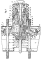
- eine Ausführung des erfindungsgemäßen Bremskraftverstärkers im Längsschnitt, teilweise weggebrochen, in der inaktiven Bereitschaftsstellung,
- Fig. 2
- die Steuergruppe des in Fig. 1 dargestellten Bremskraftverstärkers in der vom Fahrer eingesteuerten Vollbremsstellung;
- Fig. 3
- die Steuergruppe des in Fig. 1 dargestellten Bremskraftverstärkers in der Lösestellung mit geschaltetem Elektromagneten; und
- Fig. 4
- eine diagrammatische Darstellung der Kraft-Weg-Kennlinien des in Fig. 1 bis 3 dargestellten Systems.
- Fig. 1
- an embodiment of the brake booster according to the invention in longitudinal section, partially broken away, in the inactive standby position,
- Fig. 2
- the control group of the brake booster shown in FIG. 1 in the full braking position activated by the driver;
- Fig. 3
- the control group of the brake booster shown in Figure 1 in the release position with the solenoid switched. and
- Fig. 4
- a diagrammatic representation of the force-displacement characteristics of the system shown in Figs. 1 to 3.
Das lediglich schematisch angedeutete Verstärkergehäuse 1
des in der Zeichnung dargestellten erfindungsgemäßen Unterdruckbremskraftverstärkers
ist durch eine axial bewegliche
Wand 2 in eine Arbeitskammer 3 und eine Unterdruckkammer 4
unterteilt. Die axial bewegliche Wand 2 besteht aus einem
aus Blech tiefgezogenen Membranteller 8 und einer daran anliegenden
flexiblen Membran 18, die nicht näher dargestellt
zwischen dem äußeren Umfang des Membrantellers 8 und dem
Verstärkergehäuse 1 eine Rollmembran als Abdichtung bildet.The amplifier housing 1, which is only indicated schematically
of the vacuum brake booster according to the invention shown in the drawing
is axially movable
Wall 2 into a working
Ein durch eine Betätigungsstange 7 betätigbares Steuerventil
12 ist in einem im Verstärkergehäuse 1 abgedichtet geführten,
die bewegliche Wand 2 tragenden Steuergehäuse 5 untergebracht
und besteht aus einem am Steuergehäuse 5 ausgebildeten
ersten Dichtsitz 15, einem an einem mit der Betätigungsstange
7 verbundenen Ventilkolben 9 ausgebildeten zweiten
Dichtsitz 16 sowie einem mit beiden Dichtsitzen 15,16
zusammenwirkenden, in einem im Steuergehäuse 5 abgedichtet
angeordneten Führungsteil 21 geführten Ventilkörper 10, der
mittels einer sich am Führungsteil 21 abstützenden Ventilfeder
22 gegen die Ventilsitze 15,16 gedrückt wird. Die Arbeitskammer
3 ist mit der Unterdruckkammer 4 über einen
seitlich im Steuergehäuse 5 verlaufenden Kanal 28 verbindbar.A control valve which can be actuated by an actuating
Die Bremskraft wird über eine stirnseitig an einem Vorderteil
42 des Steuergehäuses 5 anliegende gummielastische Reaktionsscheibe
6 sowie eine einen Kopfflansch 23 aufweisende
Druckstange 14 auf einen Betätigungskolben eines nicht dargestellten
Hauptzylinders der Bremsanlage übertragen, der an
der unterdruckseitigen Verstärkergehäusehälfte angebracht
ist.The braking force is via a front on a
Eine in der Zeichnung schematisch dargestellte Rückstellfeder
26, die sich an der unterdruckseitigen Stirnwand
des Verstärkergehäuses 1 abstützt, hält die bewegliche Wand
2 in der gezeigten Ausgangsstellung. Außerdem ist eine zweite
Druckfeder bzw. Kolbenstangenrückholfeder 27 vorgesehen,
die einerseits indirekt an der Betätigungsstange 7 und andererseits
am Führungsteil 21 abgestützt ist und deren Kraft
für eine Vorspannung des Ventilkolbens 9 bzw. seines Dichtsitzes
16 gegenüber dem Ventilkörper 10 sorgt.A return spring shown schematically in the
Um die Arbeitskammer 3 bei der Betätigung des Steuerventils
12 mit der Atmosphäre verbinden zu können, ist schließlich
im Steuergehäuse 5 ein annähernd radial verlaufender Kanal
29 ausgebildet. Die Rückkehrbewegung des Ventilkolbens 9 am
Ende eines Bremsvorganges wird dabei durch ein Querglied 11
begrenzt, das in der in der Zeichnung gezeigten Lösestellung
des Unterdruckbremskraftverstärkers an einem im Verstärkergehäuse
1 ausgebildeten Anschlag 38 anliegt.To the working
Wie der Zeichnung weiter zu entnehmen ist, ist der Ventilkörper
10 zylindrisch ausgebildet und weist eine mit dem
ersten Dichtsitz 15 zusammenwirkende ringförmige erste
Dichtfläche 44 sowie eine mit dem zweiten Dichtsitz 16 zusammenwirkende
ringförmige zweite Dichtfläche 45 auf, die in
Betätigungsrichtung des Bremskraftverstärkers hintereinander
angeordnet sind und gleiche Durchmesser aufweisen. Außerdem
weist der Ventilkörper 10 an seinem den Dichtsitzen 15, 16
abgewandten Ende eine radial innen ausgebildete Dichtlippe
13 auf, die im montierten Zustand des Ventilkörpers 10 im
Steuergehäuse 5 an dem vorhin erwähnten Führungsteil 21
dichtend anliegt, so daß im Steuergehäuse 5 ein pneumatischer
Raum 17 begrenzt ist. Der vorhin erwähnte Kanal 28
verbindet dabei vorzugsweise den pneumatischen Raum 17 mit
der Unterdruckkammer 4, so daß der auf der den Dichtflächen
44 und 45 abgewandten Seite des Ventilkörpers 10 ausgebildete
pneumatische Raum 17 ständig der Wirkung des in der Unterdruckkammer
4 herrschenden Unterdruckes ausgesetzt ist.As can be seen from the drawing, the
Um eine von der Betätigungsstange 7 unabhängige Fremdbetätigung
des erfindungsgemäßen Bremskraftverstärkers einzuleiten
ist koaxial zu den Dichtsitzen 15,16 ein dritter
Dichtsitz 24 vorgesehen, dessen Durchmesser sowohl dem des
zweiten Dichtsitzes 16 als auch dem der den pneumatischen
Raum 17 begrenzenden Dichtlippe 13 entspricht. Der dritte
Dichtsitz 24 ist mittels eines Elektromagneten 20 betätigbar,
der vorzugsweise in einem mit dem Ventilkolben 9
fest verbundenen Gehäuse 25 angeordnet ist und demnach zusammen
mit dem Ventilkolben 9 im Steuergehäuse 5 verschiebbar
ist. Der Elektromagnet 20 besteht aus einer innerhalb
des Gehäuses 25 angeordneten Spule 36 sowie einem axial verschiebbar
angeordneten zylindrischen Anker 31, der teilweise
in einem das Gehäuse 25 verschließenden Verschlußteil 30
geführt wird und an dem sich eine Kraftübertragungshülse 19
abstützt, die den vorhin erwähnten dritten Dichtsitz 24
trägt. Zwischen dem Ventilkolben 9 und der Kraftübertragungshülse
19 ist eine Druckfeder 32 angeordnet, die den
Anker 31 in seiner Ausgangslage hält, in der der dritte
Dichtsitz 24 gegenüber dem am Ventilkolben 9 ausgebildeten
zweiten Dichtsitz 16 axial versetzt angeordnet ist. Das im
Steuergehäuse 5 geführte Verschlußteil 30 liegt unter Zwischenschaltung
einer Übersetzungsscheibe 33 an der vorhin
erwähnten Reaktionsscheibe 6 an und ermöglicht eine Übertragung
der an der Betätigungsstange 7 eingeleiteten Eingangskraft
auf die Reaktionsscheibe 6.To an independent actuation of the actuating
Bei der in der Zeichnung gezeigten Ausführung des erfindungsgemäßen
Bremskraftverstärkers sind schließlich elektrische
Schaltmittel 47, 48 vorgesehen, die insbesondere bei
Bremsvorgängen wichtig sind, bei denen zusätzlich zur
Fahrer-betätigung der Elektromagnet 20 angesteuert wird, um
unabhängig vom Fahrerwillen eine Vollbremsung herbeizuführen
(sog. Bremsassistentfunktion). Dabei ist von besonderer Bedeutung,
daß die Schaltmittel 47, 48 bei jeder Bremsung betätigt
werden. Gleichzeitig muß gewährleistet werden, daß
der Elektromagnet 20 nach Beendigung des fremdkraftunterstützten
Bremsvorganges sicher abgeschaltet wird. Die gezeigten
Schaltmittel bestehen dabei aus einem vorzugsweise
am Ventilkolben 9 bzw. dem Gehäuse 25 des Elektromagneten 20
befestigten, zwei Schaltstellungen aufweisenden Mikroschalter
47 sowie einem den Mikroschalter 47 durch eine translatorische
Bewegung betätigenden Betätigungselement 48, das
in einer im Steuergehäuse 5 vorgesehenen Bohrung abgedichtet
geführt ist und mit einem verstärkergehäusefesten Anschlag
zusammenwirkt, der das Bezugszeichen 49 trägt und beispielsweise
durch einen radialen Kragen der hinteren Verstärkergehäushälfte
gebildet sein kann. Zwischen dem Betätigungselement
48 und dem Steuergehäuse 5 ist eine Druckfeder
50 angeordnet, so daß das dem Mikroschalter 47 abgewandte
Ende des Betätigungselements 48 unter einer Vorspannung am
Anschlag 49 anliegt.In the embodiment of the invention shown in the drawing
After all, brake boosters are electrical
Switching means 47, 48 are provided, in particular at
Braking are important, in addition to
Driver actuation of the
Die Funktion des hier beschriebenen bzw. dargestellten, fremdbetätigbaren Bremskraftverstärkers ist in der eingangs erwähnten internationalen Patentanmeldung genau beschrieben, so daß sie im vorliegenden Text nicht wiederholt zu werden braucht.The function of the described or illustrated here externally actuated brake booster is in the entrance international patent application mentioned in detail, so that they are not repeated in the present text are needed.
In der in Fig. 2 dargestellten, durch eine Fahrerbetätigung
eingesteuerten Vollbremsstellung liegt die erste Dichtfläche
44 an dem ersten Dichtsitz 15 an, wodurch die Verbindung
zwischen den beiden Kammern 3,4 des Bremskraftverstärkers
unterbrochen ist. Dabei entsteht durch Verschieben des Ventilkolbens
9 in Betätigungsrichtung zwischen der zweiten
Dichtfläche 45 und dem am Ventilkolben 9 ausgebildeten zweiten
Dichtsitz 16 ein Spalt, der ein Einströmen der Atmosphäre
in die Arbeitskammer 3 und somit den Aufbau einer pneumatischen
Druckdifferenz im Verstärkergehäuse 1 ermöglicht.In the one shown in FIG. 2, by driver actuation
when the full braking position is activated, the first sealing surface is located
44 on the first sealing
Fig. 3 zeigt schließlich den Zustand, der nach einer Wegnahme
der Betätigungskraft durch den Fahrer bei eingeschaltetem
Elektromagneten 20 auftritt. In diesem Zustand wird die
Funktion des ersten Dichtsitzes 15 von dem dritten Dichtsitz
24 übernommen, der gleichzeitig den Ventilkörper 10 entgegen
der Betätigungsrichtung verschoben hat, so daß eine UnterStützung
der vom Fahrer eingeleiteten Bremsung erfolgt ist.
Die Wegnahme der Betätigungskraft bzw. der Fahrerwunsch, die
Bremsung zu beenden, wird von den vorhin erwähnten elektrischen
Schaltmitteln 47,48 (sog. Löseschalter) erkannt, die
ein Abschalten des Elektromagneten 20 bewirken. Durch die
Wirkung der Druckfeder 32 kehrt die Hülse 19 zurück in ihre
Ausgangslage, so daß sowohl der am Ventilkolben 9 ausgebildete
zweite Dichtsitz 16 als auch der am Steuergehäuse 5
ausgebildete erste Dichtsitz 15 geschlossen werden können.Fig. 3 finally shows the state after removal
the actuating force by the driver when switched on
Durch die erfindungsgemäße Ausbildung des Steuerventils 12
des fremdansteuerbaren Bremskraftverstärkers, insbesondere
dadurch, daß die beiden Dichtsitze 15,16 sowie die Dichtlippe
13 identische Durchmesser aufweisen, wird erreicht,
daß bei einer Fremdbetätigung des Steuerventils 12 durch den
Elektromagneten 20 keine pneumatisch bedingten Kraftkomponenten
wirksam werden können, da sich die Wirkungen der
pneumatischen Druckdifferenz am Ventilkörper 10 gegenseitig
kompensieren. Selbstverständlich sind auch andere Ausführungen
des Ventilkörpers 10 denkbar; so kann anstelle der
Dichtlippe 13 am Ventilköper 10 eine Rollfalte verwendet
werden, die der Anbindung des Ventilkörpers 10 an das Führungsteil
21 dient.The inventive design of the
Die in Fig. 4 gezeigte diagrammatische Darstellung der
Kraft-Weg-Kennlinien zeigt den Einfluß der Auslegung der die
Hülse 19 vorspannenden Feder 32. Wie der Zeichnung zu entnehmen
ist, zeigt der mit I1 gekennzeichnete Verlauf eine
Kraft-Weg-Kennlinie des Elektromagneten 20 bei dessen Ansteuerung
mit einem ersten Stromwert, während die mit I2,3,4
gekennzeichneten Verläufe einer zweiten, dritten und vierten
Kraft-Weg-Kennlinie des Elektromagneten 20 bei dessen Ansteuerung
mit einem zweiten, dritten und vierten Stromwert
entsprechen. Der mit II gekennzeichnete Verlauf stellt
schließlich das Verhalten des durch den Anker 31 des Elektromagneten
20, die Feder 32, die Hülse 19, den Ventilkörper
10 sowie die Ventilfeder 22 gebildeten Verbrauchersystems
dar. Der erste Abschnitt AB der Kennlinie II zeigt die Wirkung
der Druckfeder 32 zwischen Hülse 19 und Ventilkolben 9,
deren Kraft überwunden werden muß, bevor der dritte Dichtsitz
24 an der ersten Dichtfläche 44 des Ventilkörpers 10
zur Anlage kommt. Der zweite Abschnitt BC, der einer pneumatischen
Haltephase entspricht, zeigt einen Anstieg der vom
Elektromagneten 20 aufzubringenden Kraft, mit der der dritte
Dichtsitz 24 in das Material der Dichtfläche 44 hineingedrückt
wird, bis im Schnittpunkt C der Kennlinie II mit dem
Verlauf I3 ein Verschieben des Ventilkörpers 10 gegen die
Kraft der Ventilfeder 22 und somit ein Druckaufbau im System
beginnt. Der Abschnitt CD entspricht schließlich einem Bereich,
in dem das Verbrauchersystem durch Änderungen der dem
Elektromagneten 20 zuzuführenden Stromwerte zwischen I3 und
I4 stabil einstellbar ist, d.h., in dem ein definierter Spalt
zwischen dem zweiten Dichtsitz 16 und der zweiten Dichtfläche
45 des Ventilkörpers 10 und somit ein definierter Gradient
des in der Arbeitskammer 3 herrschenden pneumatischen
Druckes eingestellt werden kann. Der Berührungspunkt D der
Kraft-Weg-Kennlinie I4 mit der Verbraucherkennlinie II stellt
gleichzeitig den Übergang zwischen dem stabilen Druckaufbaubereich
und einem instabilen Bereich dar, in dem die Kraft-Weg-Kennlinie
I4 des Elektromagneten 20 eine deutlich größere
Steigung als die Verbraucherkennlinie II aufweist und in dem
die Unterstützung des Fahrers bei Panikbremsungen (sog.
Bremsassistentfunktion) stattfindet. Ein stabiler Druckabbau
findet im Bereich BA der Verbraucherkennlinie II statt, in
dem dem Elektromagneten 20 Stromwerte zwischen I1 und I2 zugeführt
werden. The diagrammatic representation of the force-displacement characteristic curves shown in FIG. 4 shows the influence of the design of the
- 11
- VerstärkergehäuseAmplifier housing
- 22nd
- bewegliche Wandmovable wall
- 33rd
- ArbeitskammerChamber of Labor
- 44th
- UnterdruckkammerVacuum chamber
- 55
- SteuergehäuseTiming case
- 66
- ReaktionsscheibeReaction disc
- 77
- BetätigungsstangeOperating rod
- 88th
- MembrantellerMembrane plate
- 99
- VentilkolbenValve piston
- 1010th
- VentilkörperValve body
- 1111
- QuergliedCross member
- 1212th
- SteuerventilControl valve
- 1313
- DichtlippeSealing lip
- 1414
- DruckstangePush rod
- 1515
- DichtsitzSealing seat
- 1616
- DichtsitzSealing seat
- 1717th
- Raumroom
- 1818th
- RollmembranRoll membrane
- 1919th
- HülseSleeve
- 2020th
- ElektromagnetElectromagnet
- 2121
- FührungsteilGuide part
- 2222
- VentilfederValve spring
- 2323
- KopfflanschHead flange
- 2424th
- DichtsitzSealing seat
- 2525th
- Gehäusecasing
- 2626
- RückstellfederReturn spring
- 2727
- KolbenstangenrückholfederPiston rod return spring
- 2828
- Kanalchannel
- 2929
- Kanalchannel
- 3030th
- Verschlußteil Closure part
- 3131
- Ankeranchor
- 3232
- Federfeather
- 3333
- ÜbersetzungsscheibeTranslation disc
- 3434
- Raumroom
- 3535
- FortsatzContinuation
- 3636
- SpuleKitchen sink
- 3737
- Flächearea
- 3838
- Anschlagattack
- 3939
- Kanalchannel
- 4040
- Federfeather
- 4141
- DichtlippeSealing lip
- 4242
- VorderteilFront part
- 4343
- RingraumAnnulus
- 4444
- DichtflächeSealing surface
- 4545
- DichtflächeSealing surface
- 4646
- SpuleKitchen sink
- 4747
- MikroschalterMicroswitch
- 4848
- BetätigungselementActuator
- 4949
- Anschlagattack
- 5050
- Federfeather
Claims (5)
- Pneumatic brake force booster for automotive vehicles which includes a booster housing having its interior subdivided by a movable wall into a first chamber (vacuum chamber) and a second chamber (working chamber), and a control housing accommodating a control valve that controls a pneumatic pressure differential which acts upon the movable wall, the control valve comprising a first sealing seat that is provided on the control housing, a second sealing seat provided on a valve piston, and a third sealing seat provided on a sleeve, the sealing seats interacting with an elastic valve member, wherein the control valve is operable by an actuating rod, on the one hand, and by an electromagnet independently of the actuating rod, on the other hand, the armature of the electromagnet being in a force-transmitting interaction with the third sealing seat, wherein the valve member delimits a pneumatic chamber in the control housing on its side remote from the sealing seats,
characterized in that a permanent pneumatic connection between the pneumatic chamber (17) and the vacuum chamber (4) is provided, and in that both the second (16) and the third sealing seat (24) and the valve member (10) in its part (sealing lip 13) delimiting the pneumatic chamber (17) in the control housing (5) have almost identical diameters. - Brake force booster as claimed in claim 1,
characterized in that the diameters of the second (16) and the third sealing seat (24) and the valve member (10 or 13) range in a tolerance width of 1 mm. - Brake force booster as claimed in claim 1 or claim 2,
characterized in that the pneumatic chamber (17) is delimited by a cylindrical part (guide part 21) which cooperates with a sealing lip (13) designed on the valve member (10). - Brake force booster as claimed in claim 1 or claim 2,
characterized in that the pneumatic chamber (17) is delimited by a cylindrical part to which the valve member is connected by way of a rolling diaphragm having a mean diameter which corresponds to that of the first and the third sealing seat. - Brake force booster as claimed in any one of the preceding claims,
characterized in that the valve member (10) has two sealing surfaces (44, 45) which preferably have an annular configuration and are arranged one behind the other in the actuating direction, and the first (15) and the third (24) respectively the second sealing seat (16) are movable into abutment with the said sealing surfaces.
Applications Claiming Priority (3)
| Application Number | Priority Date | Filing Date | Title |
|---|---|---|---|
| DE19611555A DE19611555A1 (en) | 1996-03-23 | 1996-03-23 | Pneumatic brake booster |
| DE19611555 | 1996-03-23 | ||
| PCT/EP1997/001454 WO1997035754A1 (en) | 1996-03-23 | 1997-03-21 | Pneumatic brake booster |
Publications (2)
| Publication Number | Publication Date |
|---|---|
| EP0886595A1 EP0886595A1 (en) | 1998-12-30 |
| EP0886595B1 true EP0886595B1 (en) | 2001-10-04 |
Family
ID=7789225
Family Applications (1)
| Application Number | Title | Priority Date | Filing Date |
|---|---|---|---|
| EP97914290A Expired - Lifetime EP0886595B1 (en) | 1996-03-23 | 1997-03-21 | Pneumatic brake booster |
Country Status (5)
| Country | Link |
|---|---|
| US (1) | US6070514A (en) |
| EP (1) | EP0886595B1 (en) |
| JP (1) | JP2000507185A (en) |
| DE (2) | DE19611555A1 (en) |
| WO (1) | WO1997035754A1 (en) |
Families Citing this family (14)
| Publication number | Priority date | Publication date | Assignee | Title |
|---|---|---|---|---|
| DE19748657A1 (en) * | 1997-11-04 | 1999-05-12 | Lucas Ind Plc | Pneumatic brake booster with mechanical and electromagnetic actuation |
| DE19750383C1 (en) * | 1997-11-13 | 1998-12-24 | Lucas Ind Plc | Pneumatic brake booster for motor vehicle |
| DE19752868A1 (en) * | 1997-11-28 | 1999-06-10 | Lucas Ind Plc | Pneumatic brake booster especially for cars |
| JP4491673B2 (en) * | 1999-06-30 | 2010-06-30 | 日立オートモティブシステムズ株式会社 | Control booster |
| DE19937769B4 (en) * | 1999-08-10 | 2005-06-09 | Lucas Industries P.L.C., Solihull | Pneumatic brake booster and method for its production |
| DE10010385B4 (en) * | 2000-03-03 | 2005-06-16 | Lucas Varity Gmbh | Vacuum brake booster with improved magnetless emergency brake assistance |
| JP2002137726A (en) * | 2000-10-31 | 2002-05-14 | Tokico Ltd | Brake booster |
| FR2817524B1 (en) * | 2000-12-06 | 2003-04-04 | Bosch Gmbh Robert | BRAKE ASSIST MOTOR FOR MOTOR VEHICLE |
| JP4585695B2 (en) * | 2001-01-23 | 2010-11-24 | 日立オートモティブシステムズ株式会社 | Automatic brake device |
| FR2834339B1 (en) * | 2001-12-31 | 2004-02-27 | Bosch Gmbh Robert | PNEUMATIC CYLINDER FOR THE TESTING OF A SERVOMOTOR |
| DE10359175A1 (en) * | 2003-05-14 | 2004-12-02 | Continental Teves Ag & Co. Ohg | Housing module for a brake booster |
| DE502004003054D1 (en) | 2003-05-14 | 2007-04-12 | Continental Teves Ag & Co Ohg | HOUSING MODULE FOR A BRAKE POWER AMPLIFIER |
| CN108223837B (en) * | 2017-08-28 | 2019-11-08 | 河南航天液压气动技术有限公司 | A kind of solenoid valve |
| DE102021201466A1 (en) | 2021-02-16 | 2022-08-18 | Continental Teves Ag & Co. Ohg | Brake device that can be operated independently of the driver |
Family Cites Families (17)
| Publication number | Priority date | Publication date | Assignee | Title |
|---|---|---|---|---|
| GB1363241A (en) * | 1971-02-24 | 1974-08-14 | Automotive Prod Co Ltd | Diaphragms |
| CA973462A (en) * | 1971-02-25 | 1975-08-26 | Per A. Jaatinen | Continuous action sheet press |
| DE3413739C2 (en) * | 1984-04-12 | 1993-12-23 | Teves Gmbh Alfred | Vacuum brake booster |
| FR2587956B1 (en) * | 1985-09-30 | 1987-12-24 | Bendix France | BRAKE ASSIST MOTOR |
| DE3915219A1 (en) * | 1989-05-10 | 1990-11-15 | Teves Gmbh Alfred | VACUUM BRAKE POWER AMPLIFIER, ESPECIALLY FOR MOTOR VEHICLES |
| FR2667368B1 (en) * | 1990-09-28 | 1994-10-21 | Bendix Europ Services Tech | VACUUM SERVOMOTOR. |
| DE4211849A1 (en) * | 1992-04-08 | 1993-10-14 | Lucas Ind Plc | Pneumatic brake booster with electromagnetic auxiliary control, in particular for motor vehicles |
| WO1994011226A1 (en) * | 1992-11-13 | 1994-05-26 | Itt Automotive Europe Gmbh | Vacuum power brake |
| DE4238333C2 (en) * | 1992-11-13 | 2001-10-11 | Continental Teves Ag & Co Ohg | Vacuum brake booster |
| DE4405076C2 (en) * | 1994-02-17 | 1997-01-02 | Lucas Ind Plc | Pneumatic brake booster with electromagnetic auxiliary control, in particular for motor vehicle brake systems |
| JP3131094B2 (en) * | 1994-05-25 | 2001-01-31 | アイシン精機株式会社 | Negative pressure booster |
| DE4422027C2 (en) * | 1994-06-23 | 1998-01-29 | Lucas Ind Plc | Pneumatic brake booster and method for its production |
| DE4432583C1 (en) * | 1994-09-13 | 1995-09-14 | Lucas Ind Plc | Brake system for motor vehicle |
| US5711202A (en) * | 1995-07-27 | 1998-01-27 | Aisin Seiki Kabushiki Kaisha | Vacuum servo unit for a vehicle braking system |
| DE19541101A1 (en) * | 1995-11-06 | 1997-05-07 | Teves Gmbh Alfred | Method for operating a pneumatic brake booster |
| JPH09164939A (en) * | 1995-12-18 | 1997-06-24 | Aisin Seiki Co Ltd | Negative pressure type assistor |
| US5937727A (en) * | 1996-05-23 | 1999-08-17 | Itt Manufacturing Enterprises Inc. | Brake servo device for motor vehicles |
-
1996
- 1996-03-23 DE DE19611555A patent/DE19611555A1/en not_active Withdrawn
-
1997
- 1997-03-21 JP JP9534023A patent/JP2000507185A/en active Pending
- 1997-03-21 WO PCT/EP1997/001454 patent/WO1997035754A1/en active IP Right Grant
- 1997-03-21 US US09/155,167 patent/US6070514A/en not_active Expired - Fee Related
- 1997-03-21 EP EP97914290A patent/EP0886595B1/en not_active Expired - Lifetime
- 1997-03-21 DE DE59704792T patent/DE59704792D1/en not_active Expired - Lifetime
Also Published As
| Publication number | Publication date |
|---|---|
| DE19611555A1 (en) | 1997-09-25 |
| JP2000507185A (en) | 2000-06-13 |
| EP0886595A1 (en) | 1998-12-30 |
| WO1997035754A1 (en) | 1997-10-02 |
| DE59704792D1 (en) | 2001-11-08 |
| US6070514A (en) | 2000-06-06 |
Similar Documents
| Publication | Publication Date | Title |
|---|---|---|
| EP0891906B1 (en) | Vacuum brake booster for motor vehicles | |
| EP0886595B1 (en) | Pneumatic brake booster | |
| DE4238333C2 (en) | Vacuum brake booster | |
| EP0866758B1 (en) | Power brake for motor vehicles | |
| EP0847353B1 (en) | Pneumatic servobrake | |
| EP2214942A2 (en) | Brake servo unit | |
| DE4301336A1 (en) | Actuating unit for an anti-lock motor vehicle brake system | |
| EP0857129A1 (en) | Process for operating a pneumatic brake servo | |
| EP1274616B1 (en) | Vacuum brake booster with mechanical emergency brake boost | |
| DE3822261A1 (en) | BRAKE CONTROL UNIT FOR MOTOR VEHICLES | |
| EP0828641B1 (en) | Brake servo device for motor vehicles | |
| DE19617589A1 (en) | Automobile braking servo with electromagnetic control valve | |
| DE19523020B4 (en) | Brake booster | |
| DE19541534A1 (en) | Brake servo for vehicle | |
| WO1996015930A1 (en) | Vacuum brake servo for motor vehicles | |
| DE4404334A1 (en) | Brake booster for vehicle ABS braking system | |
| EP1658213B1 (en) | Actuation unit for a hydraulic vehicle brake | |
| EP2379387B1 (en) | Pneumatic brake booster for a vehicle brake system | |
| DE19529387A1 (en) | Control method for operating pneumatic brake servo - has solenoid opening and closing the control valve in controlled sequence to minimise noise and vibration. | |
| DE3836113A1 (en) | Vacuum brake booster | |
| DE19617277A1 (en) | Pneumatic brake force amplifying arrangement for motor vehicle | |
| DE19601269A1 (en) | Brake booster for vehicle with booster housing | |
| DE3909924A1 (en) | Brake actuating unit for motor vehicles | |
| DE19748657A1 (en) | Pneumatic brake booster with mechanical and electromagnetic actuation | |
| DE19613508A1 (en) | Pneumatic brake servo-cylinder for motor vehicles |
Legal Events
| Date | Code | Title | Description |
|---|---|---|---|
| PUAI | Public reference made under article 153(3) epc to a published international application that has entered the european phase |
Free format text: ORIGINAL CODE: 0009012 |
|
| 17P | Request for examination filed |
Effective date: 19981023 |
|
| AK | Designated contracting states |
Kind code of ref document: A1 Designated state(s): DE FR GB |
|
| RAP1 | Party data changed (applicant data changed or rights of an application transferred) |
Owner name: CONTINENTAL TEVES AG & CO. OHG |
|
| GRAG | Despatch of communication of intention to grant |
Free format text: ORIGINAL CODE: EPIDOS AGRA |
|
| 17Q | First examination report despatched |
Effective date: 20001103 |
|
| GRAG | Despatch of communication of intention to grant |
Free format text: ORIGINAL CODE: EPIDOS AGRA |
|
| GRAH | Despatch of communication of intention to grant a patent |
Free format text: ORIGINAL CODE: EPIDOS IGRA |
|
| GRAH | Despatch of communication of intention to grant a patent |
Free format text: ORIGINAL CODE: EPIDOS IGRA |
|
| GRAA | (expected) grant |
Free format text: ORIGINAL CODE: 0009210 |
|
| AK | Designated contracting states |
Kind code of ref document: B1 Designated state(s): DE FR GB |
|
| GBT | Gb: translation of ep patent filed (gb section 77(6)(a)/1977) |
Effective date: 20011004 |
|
| REF | Corresponds to: |
Ref document number: 59704792 Country of ref document: DE Date of ref document: 20011108 |
|
| REG | Reference to a national code |
Ref country code: GB Ref legal event code: IF02 |
|
| ET | Fr: translation filed | ||
| PGFP | Annual fee paid to national office [announced via postgrant information from national office to epo] |
Ref country code: GB Payment date: 20020308 Year of fee payment: 6 |
|
| PLBE | No opposition filed within time limit |
Free format text: ORIGINAL CODE: 0009261 |
|
| STAA | Information on the status of an ep patent application or granted ep patent |
Free format text: STATUS: NO OPPOSITION FILED WITHIN TIME LIMIT |
|
| 26N | No opposition filed | ||
| PGFP | Annual fee paid to national office [announced via postgrant information from national office to epo] |
Ref country code: FR Payment date: 20030320 Year of fee payment: 7 |
|
| PG25 | Lapsed in a contracting state [announced via postgrant information from national office to epo] |
Ref country code: GB Free format text: LAPSE BECAUSE OF NON-PAYMENT OF DUE FEES Effective date: 20030321 |
|
| GBPC | Gb: european patent ceased through non-payment of renewal fee |
Effective date: 20030321 |
|
| PG25 | Lapsed in a contracting state [announced via postgrant information from national office to epo] |
Ref country code: FR Free format text: LAPSE BECAUSE OF NON-PAYMENT OF DUE FEES Effective date: 20051130 |
|
| REG | Reference to a national code |
Ref country code: FR Ref legal event code: ST Effective date: 20051130 |
|
| PGFP | Annual fee paid to national office [announced via postgrant information from national office to epo] |
Ref country code: DE Payment date: 20070331 Year of fee payment: 11 |
|
| PG25 | Lapsed in a contracting state [announced via postgrant information from national office to epo] |
Ref country code: DE Free format text: LAPSE BECAUSE OF THE APPLICANT RENOUNCES Effective date: 20070530 |
|
| PG25 | Lapsed in a contracting state [announced via postgrant information from national office to epo] |
Ref country code: FR Free format text: LAPSE BECAUSE OF NON-PAYMENT OF DUE FEES Effective date: 20040331 |