EP0886190B1 - Multispeed drive mechanism - Google Patents
Multispeed drive mechanism Download PDFInfo
- Publication number
- EP0886190B1 EP0886190B1 EP98304269A EP98304269A EP0886190B1 EP 0886190 B1 EP0886190 B1 EP 0886190B1 EP 98304269 A EP98304269 A EP 98304269A EP 98304269 A EP98304269 A EP 98304269A EP 0886190 B1 EP0886190 B1 EP 0886190B1
- Authority
- EP
- European Patent Office
- Prior art keywords
- drive
- gears
- input shaft
- platen
- gear
- Prior art date
- Legal status (The legal status is an assumption and is not a legal conclusion. Google has not performed a legal analysis and makes no representation as to the accuracy of the status listed.)
- Expired - Lifetime
Links
- 230000007246 mechanism Effects 0.000 title claims description 49
- 230000009467 reduction Effects 0.000 claims description 8
- 238000003384 imaging method Methods 0.000 claims description 7
- 108091008695 photoreceptors Proteins 0.000 description 5
- 230000008859 change Effects 0.000 description 4
- 230000008901 benefit Effects 0.000 description 3
- 238000000034 method Methods 0.000 description 2
- 230000003287 optical effect Effects 0.000 description 2
- 239000002245 particle Substances 0.000 description 2
- 238000004140 cleaning Methods 0.000 description 1
- 230000003247 decreasing effect Effects 0.000 description 1
- 239000011521 glass Substances 0.000 description 1
- 238000010438 heat treatment Methods 0.000 description 1
- 238000005286 illumination Methods 0.000 description 1
- 230000008569 process Effects 0.000 description 1
Images


Classifications
-
- G—PHYSICS
- G03—PHOTOGRAPHY; CINEMATOGRAPHY; ANALOGOUS TECHNIQUES USING WAVES OTHER THAN OPTICAL WAVES; ELECTROGRAPHY; HOLOGRAPHY
- G03G—ELECTROGRAPHY; ELECTROPHOTOGRAPHY; MAGNETOGRAPHY
- G03G15/00—Apparatus for electrographic processes using a charge pattern
- G03G15/60—Apparatus which relate to the handling of originals
- G03G15/605—Holders for originals or exposure platens
-
- G—PHYSICS
- G03—PHOTOGRAPHY; CINEMATOGRAPHY; ANALOGOUS TECHNIQUES USING WAVES OTHER THAN OPTICAL WAVES; ELECTROGRAPHY; HOLOGRAPHY
- G03G—ELECTROGRAPHY; ELECTROPHOTOGRAPHY; MAGNETOGRAPHY
- G03G15/00—Apparatus for electrographic processes using a charge pattern
- G03G15/04—Apparatus for electrographic processes using a charge pattern for exposing, i.e. imagewise exposure by optically projecting the original image on a photoconductive recording material
- G03G15/041—Apparatus for electrographic processes using a charge pattern for exposing, i.e. imagewise exposure by optically projecting the original image on a photoconductive recording material with variable magnification
Definitions
- the present invention relates to a multispeed drive mechanism and, more particularly, to a multiple speed gear drive mechanism for use in driving members of a copying apparatus.
- the invention is particularly applicable to low speed copying devices and will be described with particular relevance thereto.
- the drive mechanism has broader application and may be advantageously employed in other copier and non-copier applications and environments without departing from the invention.
- Copying machines generally consist of complex systems which feed paper in, create a permanent image of an original document on the paper, and deliver the finished copy to a document receiving tray.
- the reproduced image is produced by projecting the image of the original document onto a photoconductive member or photoreceptor. Toner particles are then deposited on the photoreceptor in the areas which correspond to the image of the original document. This toner image is transferred to the paper and fused to the paper by heating the toner particles.
- the image of the original document is projected onto the photoreceptor by placing the document on a movable platen or glass tray of the copying machine and moving the platen with respect to the photoreceptor to scan the image of the original document onto the photoreceptor.
- the back and forth motion of the platen is generally provided by a drive system having a clutch.
- the platen may be moved at different speeds and reduction/enlargement lenses are used. For example, when a reduced size copy is desired, a reduction lens is selected and the platen is moved at a speed which is faster than the standard drive rate used for making same size copies. Alternatively, an enlargement lens is used and the platen is driven at a speed slower than the standard drive rate to achieve a resulting enlarged image of the original document.
- US5,113,224 discloses a reciprocating driving device having a first and a second rack for driving a reciprocating member.
- a gear set moves the reciprocating member in either a forward or reverse direction by rotating and engaging with either the first or second rack.
- the forward and reverse speeds may be different.
- JP58-68061 describes a mechanism for varying the speed with which an output shaft rotates for a fixed speed of an input shaft.
- a third shaft rotates and operates bellcrank levers to engage one of a plurality of gear pairs mounted on the input and output shafts, each gear pair providing a different gear ratio and hence, output speed.
- a speed selector device is disclosed in US2,957,360.
- a mounting plate 15 carries three output gears, each of which can mesh with one of three input gears mounted on an input shaft that passes through an aperture in the mounting plate.
- Solenoids operate to urge the mounting plate into one of three positions such that each output gear can engage with its respective input gear.
- the output gears all mesh with an internal gear that drives an output shaft the speed of which varies for a fixed input speed depending upon the gear ratios between the input and output gears.
- a copying apparatus comprises:
- the multiple speed drive mechanism addresses the disadvantages of known drive systems by providing a clutchless drive mechanism which is simple and economical.
- a multiple speed drive mechanism which includes a rotatable input shaft, a plurality of input gears of different diameters mounted on the input shaft, and a plurality of drive gears of different distances from the input shaft.
- a driven member is driven at different speeds for the same speed of the rotatable input shaft by pivoting the support member about the input shaft to provide different gear ratios.
- a movable platen is driven by the multiple speed drive mechanism at different driven speeds.
- the input shaft and the driven member are positioned at a fixed distance apart and the drive gears and input gears are sized such that the drive gears may be selectively positioned directly between the input shaft and the driven member.
- a principal advantage of the invention is the ability to drive a driven member at different speeds without the need for an expensive and complicated drive mechanism including a clutch.
- FIGURES illustrate a multiple speed drive mechanism including an input shaft having multiple input gears and multiple drive gears engaging the input gears.
- Each combination of input and drive gears is arranged to provide a different gear ratio from the input shaft to an output rack, while at the same time maintaining a fixed dimension between the output rack and the input shaft.
- the multiple speed drive mechanism shown in FIGURE 1 includes a rotatable input shaft 10 and upper and lower input gears 12, 14 mounted on the input shaft for rotation with the input shaft.
- First and second drive gears 16, 18 selectively transmit the power from the input shaft 10 to a rack 20.
- the rack 20 is preferably attached to a movable platen 22 of a copying apparatus.
- the first and second drive gears 16, 18 are rotatably mounted on a support member 24 which is a triangular shaped plate supported either above or below the gears.
- the support member 24 is rotatable about the input shaft 10 and maintains the first and second drive gears 16, 18 in engagement with the input gears 12, 14 at a fixed distance from the input shaft.
- the upper input gear 12 and the first drive gear 16 which together provide a first gear ratio are illustrated in solid lines, while the lower input gear 14 and the second drive gear 18 providing a second gear ratio are illustrated in broken lines.
- the power is transmitted from the input shaft 10 and the upper input gear 12 to the first drive gear 16 and then from the first drive gear to the rack 20.
- the speed at which the movable platen 22 is moved is determined by the rpm of the input shaft and the number of teeth on the upper input gear 12 and the first drive gear 16.
- the first drive gear 16 is larger than the upper input gear 12, however, the relative sizes of the two gears may be varied to achieve different gear ratios.
- the gear ratio of the multiple speed drive mechanism is changed by pivoting the support member 24 and the first and second drive gears 16, 18 attached to the support member about the input shaft 10 to bring different drive gears into engagement with the rack 20. Movement of the drive gears 16, 18 around the input shaft 10 is performed by adjusting the support member 24 and locking the support member in place with a locking mechanism.
- a simple lever and detent arrangement may be used as a locking mechanism to allow movement of the support member 24 from one position to another and to lock the support member in place during use.
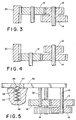
- the locking mechanism includes a shift lever 30 which is mounted either on the support member 24 or on the input shaft 10 and the shaft 32 of one of the drive gears 16.
- the shift lever 30 includes a detent 34 which receives a ball 36.
- the ball 36 is supported in a recess 38 in a frame member 40 of the copier structure.
- the ball 36 is spring biased by a spring 42 in a known manner. Spring biased balls 36 are also located at other locking locations such that the support member 24 can be locked in different positions to achieve different gear ratios.
- the multiple speed drive mechanism in the position illustrated in FIGURE 1 may be used to drive a movable platen 22 at a first drive rate, while the position of the multiple speed drive mechanism may be rotated to the position illustrated in FIGURE 2 to drive a movable platen at a second drive rate.
- the first drive gear 16 and the entire support device 24 are shifted or rotated to the left and the first drive gear 16 disengages from the platen rack 20.
- the second drive gear 18 is engaged with the rack 20. Power is transmitted from the lower input gear 14 to the second drive gear 18 and to the rack 20.
- the position of the drive mechanism illustrated in FIGURES 2 and 4 provides a different gear ratio and a higher rack 20 speed than the rack speed provided by the drive mechanism in the position of FIGURE 1 for the same input shaft 10 speed.
- each set of input and drive gears must be sized so that a constant distance D is maintained between an axis of the input shaft 10 and the rack 20 .
- This constant distance D corresponds to approximately 1 ⁇ 2 the diameter of the input gear plus the diameter of the drive gear for each input gear/drive gear combination.
- a smaller input gear 12, 14 must be used to maintain a correct constant input shaft 10 to rack 20 distance D.
- FIGURE 6 A copying apparatus according to the present invention is shown in FIGURE 6 for reproducing documents 50 at different magnifications.
- the document 50 is placed on the movable platen 22 and moved past a narrow illumination strip 52 where light from a lamp 54 is directed to the document via a reflector 56.
- a linear lens array 58 includes lenses 60, 62 for reproducing the document at different magnifications.
- the image is transmitted through a selected lens to the surface of a photoconductive drum 64.
- the imaging system includes a charging station 66, a development station 68, a transfer station 70, a cleaning station 72, and a fusing station 74 . The processes performed at each of these xerographic stations are well known in the art.
- a magnification is selected by an operator at an input panel and the multispeed platen drive 80 and lens position drive 82 move the appropriate lens 60, 62 and gears 16, 18 into position for the desired magnification.
- the movable platen 22 is then moved by the multispeed drive mechanism illustrated in FIGURES 1 - 4 at a desired speed for the selected magnification.
- the increase in the speed of the platen with a gear ratio such as that shown in FIGURE 2 is used in combination with a reduction lens for reduced size copying.
- the optical reduction of the copying apparatus requires that the speed of the platen be increased by the reciprocal of a desired reduction ratio.
- Additional gear ratios can be easily added to the configuration of the multiple speed drive mechanism illustrated in the FIGURES by arranging additional input gears and drive gears concentrically around the input shaft 10. These additional gear combinations will be sized to maintain the constant dimension D between the rack 20 and the input shaft 10.
- FIGURE 7 illustrates such an arrangement with a fixed axis circular output gear 90 positioned for engagement with one of the drive gears 16, 18.
- An output shaft 92 of the output gear 90 may be connected to one of many different driven members of a printing apparatus which is to be driven at different speeds.
- the multiple speed drive mechanism of FIGURE 7 is operated in the same manner as the drive mechanism of FIGURES 1 and 2 by rotating the support device 24 about the input shaft 10 .
- the drive mechanism may also be used in other systems within the copying machine.
- the multiple speed drive mechanism may be used to drive a shuttle mechanism for offset stacking of copies in a stacking tray by connection of the rack 20 to the shuttle mechanism.
- the multiple speed drive mechanism may also be used in a stacker to drive sheets of paper of different lengths into the sheet receiving tray of a printing apparatus in the same time interval. This is achieved by increasing the sheet delivery speed for larger size sheets and decreasing the sheet delivery speed for smaller size sheets.
- the sheet speed is adjusted by connecting the output shaft 92 to a variable speed feed roller 94 .
- the drive mechanism may be used to drive an inverter mechanism for double-sided copying.
- the inverter may be operated at different speeds to accommodate different size sheets in the same time interval in the same manner as the stacker by connecting the output shaft 92 to a variable speed feed roller 94 .
- the circular output gear 90 a convenient speed change can be performed in a conventional optical scanning system with a fixed platen.
- the scanning speed can be adjusted by connecting the multiple speed drive mechanism to a variable speed sheet feeding member to achieve standard size, enlargement, and reduction copying.
- Another application where a speed change is used in a printing apparatus is with a roll fuser.
- the fusing time can be changed by changing the speed with which the sheets are fed through the fuser.
- the output shaft 92 of the circular output gear 90 is used to drive a feed roller 94 at a variable speed to feed the sheets through the fuser.
- the drive mechanism may also be advantageously employed in non-copier environments.
- FIGURE 5 illustrates a simple shift lever 30 for shifting between respective drive gears 16, 18 of the multispeed drive mechanism
- this shift lever may be actuated either manually or automatically.
- the shift lever 30 may be connected to a solenoid so that the shift lever is actuated according to an electronic control algorithm of the printing apparatus.
- the shift lever 30 may also be actuated by interconnection to a related function of the printing apparatus such as a paper size selection mechanism. With this arrangement, for example, adjustment of the paper size may also adjust the multispeed drive mechanism to change a speed of a feed roller of the paper stacker simultaneously with the paper size adjustment.
Landscapes
- Physics & Mathematics (AREA)
- General Physics & Mathematics (AREA)
- Structure Of Transmissions (AREA)
- Optical Systems Of Projection Type Copiers (AREA)
- Electrophotography Configuration And Component (AREA)
- Gear Transmission (AREA)
- Exposure Or Original Feeding In Electrophotography (AREA)
Applications Claiming Priority (2)
| Application Number | Priority Date | Filing Date | Title |
|---|---|---|---|
| US08/876,607 US5839036A (en) | 1997-06-16 | 1997-06-16 | Multispeed drive mechanism |
| US876607 | 1997-06-16 |
Publications (3)
| Publication Number | Publication Date |
|---|---|
| EP0886190A2 EP0886190A2 (en) | 1998-12-23 |
| EP0886190A3 EP0886190A3 (en) | 1999-12-08 |
| EP0886190B1 true EP0886190B1 (en) | 2004-03-10 |
Family
ID=25368137
Family Applications (1)
| Application Number | Title | Priority Date | Filing Date |
|---|---|---|---|
| EP98304269A Expired - Lifetime EP0886190B1 (en) | 1997-06-16 | 1998-05-29 | Multispeed drive mechanism |
Country Status (4)
| Country | Link |
|---|---|
| US (1) | US5839036A (enExample) |
| EP (1) | EP0886190B1 (enExample) |
| JP (1) | JPH1115212A (enExample) |
| DE (1) | DE69822250T2 (enExample) |
Families Citing this family (5)
| Publication number | Priority date | Publication date | Assignee | Title |
|---|---|---|---|---|
| US6041198A (en) * | 1998-06-24 | 2000-03-21 | Avision Inc. | Dual resolution scanner |
| US6851368B2 (en) * | 2001-08-29 | 2005-02-08 | Heidelberger Druckmaschinen Ag | Rotary printing press having a switchable speed-change gear mechanism with plant gears |
| US20040016868A1 (en) * | 2002-07-23 | 2004-01-29 | Cherry Patrick A. | Image processing apparatus |
| US20040246539A1 (en) * | 2003-06-09 | 2004-12-09 | Kabushiki Kaisha Toshiba | Image read apparatus |
| US7274903B2 (en) * | 2004-03-25 | 2007-09-25 | Lexmark International, Inc. | Integrated fuser unit and drive system for use in an electrophotographic imaging process |
Family Cites Families (8)
| Publication number | Priority date | Publication date | Assignee | Title |
|---|---|---|---|---|
| US2957360A (en) * | 1958-07-18 | 1960-10-25 | Gen Motors Corp | Speed selector device |
| JPS5868061A (ja) * | 1981-10-19 | 1983-04-22 | Canon Inc | 可変倍複写装置 |
| US4542983A (en) * | 1983-09-29 | 1985-09-24 | Xerox Corporation | Multi-magnification reproduction device utilizing linear lens assembly |
| JPH061099B2 (ja) * | 1986-02-19 | 1994-01-05 | キヤノン株式会社 | 画像形成装置 |
| US4796053A (en) * | 1986-10-04 | 1989-01-03 | Sharp Kabushiki Kaisha | Magnification converting mechanism for a variable magnification copying apparatus |
| US5113224A (en) * | 1989-10-13 | 1992-05-12 | Canon Kabushiki Kaisha | Reciprocating driving device |
| JP2682907B2 (ja) * | 1991-05-23 | 1997-11-26 | シャープ株式会社 | 原稿台駆動装置並びに原稿台移動型複写機 |
| JP2889066B2 (ja) * | 1992-01-21 | 1999-05-10 | シャープ株式会社 | 搬送台駆動装置 |
-
1997
- 1997-06-16 US US08/876,607 patent/US5839036A/en not_active Expired - Lifetime
-
1998
- 1998-05-29 DE DE69822250T patent/DE69822250T2/de not_active Expired - Lifetime
- 1998-05-29 EP EP98304269A patent/EP0886190B1/en not_active Expired - Lifetime
- 1998-06-03 JP JP10154476A patent/JPH1115212A/ja active Pending
Also Published As
| Publication number | Publication date |
|---|---|
| EP0886190A3 (en) | 1999-12-08 |
| JPH1115212A (ja) | 1999-01-22 |
| EP0886190A2 (en) | 1998-12-23 |
| DE69822250D1 (de) | 2004-04-15 |
| US5839036A (en) | 1998-11-17 |
| DE69822250T2 (de) | 2004-08-12 |
Similar Documents
| Publication | Publication Date | Title |
|---|---|---|
| CA1097723A (en) | Extended range variable magnification reproduction machine | |
| EP0238761B1 (en) | Reprographic machine | |
| EP0041602B1 (en) | Electrophotographic copier and method for producing copies in booklet form | |
| US4247192A (en) | Copying machine | |
| CA1060532A (en) | Dual purpose document handling system | |
| US4792828A (en) | Image forming apparatus for forming a plurality of image from different originals on one transfer sheet | |
| US5956152A (en) | Document reading apparatus | |
| SU1074418A3 (ru) | Электрофотографический копировальный аппарат | |
| US4394083A (en) | Imaging system for a multi-magnification copier utilizing gradient index lens array | |
| EP0886190B1 (en) | Multispeed drive mechanism | |
| US4057342A (en) | Illumination slit for a reproducing machine | |
| US5097290A (en) | Scanner for scanning an object from a plurality of positions | |
| US4538903A (en) | Multiple magnification mode copying apparatus | |
| US4435070A (en) | Variable magnification copying apparatus | |
| CA1100567A (en) | Variable magnification reproducing apparatus | |
| CA1252325A (en) | Multiple magnification mode copying apparatus | |
| US4076416A (en) | Illumination slit for and a process of use thereof in a reproducing machine | |
| JPS582857A (ja) | 複写方法 | |
| US4727397A (en) | Book style duplex copying for short edge feed sheets | |
| US4076417A (en) | Interlocking apparatus for an optical system and reproducing machine | |
| GB2127165A (en) | Variable magnification photocopier | |
| JPS59140438A (ja) | 多重倍率モ−ド式コピ−装置 | |
| CA1102398A (en) | Drive system for multi-mode reproducing apparatus | |
| JPS61197335A (ja) | 並列搬送型複写機 | |
| JPS61189569A (ja) | 並列搬送複写機 |
Legal Events
| Date | Code | Title | Description |
|---|---|---|---|
| PUAI | Public reference made under article 153(3) epc to a published international application that has entered the european phase |
Free format text: ORIGINAL CODE: 0009012 |
|
| AK | Designated contracting states |
Kind code of ref document: A2 Designated state(s): DE FR GB |
|
| AX | Request for extension of the european patent |
Free format text: AL;LT;LV;MK;RO;SI |
|
| PUAL | Search report despatched |
Free format text: ORIGINAL CODE: 0009013 |
|
| AK | Designated contracting states |
Kind code of ref document: A3 Designated state(s): AT BE CH CY DE DK ES FI FR GB GR IE IT LI LU MC NL PT SE |
|
| AX | Request for extension of the european patent |
Free format text: AL;LT;LV;MK;RO;SI |
|
| RIC1 | Information provided on ipc code assigned before grant |
Free format text: 6G 03G 15/00 A, 6G 03G 15/041 B, 6F 16H 3/34 B, 6G 03B 27/62 B |
|
| 17P | Request for examination filed |
Effective date: 20000608 |
|
| AKX | Designation fees paid |
Free format text: DE FR GB |
|
| 17Q | First examination report despatched |
Effective date: 20011122 |
|
| REG | Reference to a national code |
Ref country code: GB Ref legal event code: FG4D |
|
| GRAP | Despatch of communication of intention to grant a patent |
Free format text: ORIGINAL CODE: EPIDOSNIGR1 |
|
| GRAS | Grant fee paid |
Free format text: ORIGINAL CODE: EPIDOSNIGR3 |
|
| GRAA | (expected) grant |
Free format text: ORIGINAL CODE: 0009210 |
|
| AK | Designated contracting states |
Kind code of ref document: B1 Designated state(s): DE FR GB |
|
| REF | Corresponds to: |
Ref document number: 69822250 Country of ref document: DE Date of ref document: 20040415 Kind code of ref document: P |
|
| ET | Fr: translation filed | ||
| PLBE | No opposition filed within time limit |
Free format text: ORIGINAL CODE: 0009261 |
|
| STAA | Information on the status of an ep patent application or granted ep patent |
Free format text: STATUS: NO OPPOSITION FILED WITHIN TIME LIMIT |
|
| 26N | No opposition filed |
Effective date: 20041213 |
|
| REG | Reference to a national code |
Ref country code: GB Ref legal event code: 746 Effective date: 20050404 |
|
| REG | Reference to a national code |
Ref country code: FR Ref legal event code: PLFP Year of fee payment: 18 |
|
| PGFP | Annual fee paid to national office [announced via postgrant information from national office to epo] |
Ref country code: GB Payment date: 20150424 Year of fee payment: 18 Ref country code: DE Payment date: 20150422 Year of fee payment: 18 |
|
| PGFP | Annual fee paid to national office [announced via postgrant information from national office to epo] |
Ref country code: FR Payment date: 20150422 Year of fee payment: 18 |
|
| REG | Reference to a national code |
Ref country code: DE Ref legal event code: R119 Ref document number: 69822250 Country of ref document: DE |
|
| GBPC | Gb: european patent ceased through non-payment of renewal fee |
Effective date: 20160529 |
|
| REG | Reference to a national code |
Ref country code: FR Ref legal event code: ST Effective date: 20170131 |
|
| PG25 | Lapsed in a contracting state [announced via postgrant information from national office to epo] |
Ref country code: FR Free format text: LAPSE BECAUSE OF NON-PAYMENT OF DUE FEES Effective date: 20160531 Ref country code: DE Free format text: LAPSE BECAUSE OF NON-PAYMENT OF DUE FEES Effective date: 20161201 |
|
| PG25 | Lapsed in a contracting state [announced via postgrant information from national office to epo] |
Ref country code: GB Free format text: LAPSE BECAUSE OF NON-PAYMENT OF DUE FEES Effective date: 20160529 |