EP0885693B1 - Hydraulischer Drehmoment-Impuls-Erzeuger - Google Patents
Hydraulischer Drehmoment-Impuls-Erzeuger Download PDFInfo
- Publication number
- EP0885693B1 EP0885693B1 EP98850089A EP98850089A EP0885693B1 EP 0885693 B1 EP0885693 B1 EP 0885693B1 EP 98850089 A EP98850089 A EP 98850089A EP 98850089 A EP98850089 A EP 98850089A EP 0885693 B1 EP0885693 B1 EP 0885693B1
- Authority
- EP
- European Patent Office
- Prior art keywords
- impulse generator
- membrane
- generator according
- drive member
- compartment
- Prior art date
- Legal status (The legal status is an assumption and is not a legal conclusion. Google has not performed a legal analysis and makes no representation as to the accuracy of the status listed.)
- Expired - Lifetime
Links
Images
Classifications
-
- B—PERFORMING OPERATIONS; TRANSPORTING
- B25—HAND TOOLS; PORTABLE POWER-DRIVEN TOOLS; MANIPULATORS
- B25B—TOOLS OR BENCH DEVICES NOT OTHERWISE PROVIDED FOR, FOR FASTENING, CONNECTING, DISENGAGING, OR HOLDING
- B25B21/00—Portable power-driven screw or nut setting or loosening tools; Attachments for drilling apparatus serving the same purpose
- B25B21/02—Portable power-driven screw or nut setting or loosening tools; Attachments for drilling apparatus serving the same purpose with means for imparting impact to screwdriver blade or nut socket
-
- Y—GENERAL TAGGING OF NEW TECHNOLOGICAL DEVELOPMENTS; GENERAL TAGGING OF CROSS-SECTIONAL TECHNOLOGIES SPANNING OVER SEVERAL SECTIONS OF THE IPC; TECHNICAL SUBJECTS COVERED BY FORMER USPC CROSS-REFERENCE ART COLLECTIONS [XRACs] AND DIGESTS
- Y10—TECHNICAL SUBJECTS COVERED BY FORMER USPC
- Y10S—TECHNICAL SUBJECTS COVERED BY FORMER USPC CROSS-REFERENCE ART COLLECTIONS [XRACs] AND DIGESTS
- Y10S277/00—Seal for a joint or juncture
- Y10S277/926—Seal including fluid pressure equalizing or balancing feature
Definitions
- This invention relates to a hydraulic torque impulse generator of the kind having a motor rotated drive member formed with a fluid chamber, an impulse receiving output member coaxial with the drive member and extending into the fluid chamber, a hydraulic pressure peak generating means in the fluid chamber for producing torque impulses at relative rotation between the drive member and the output member, and a variable volume fluid accumulator chanber located in the drive member and connected to the fluid chamber for compensating for occurring volume changes in the hydraulic fluid.
- an impulse generator of this type is previously described in US 4,789,373.
- an annular accumulator chamber is located in a coaxial relationship with the output shaft and communicating with the fluid chamber via the clearance seal arround the output shaft.
- An annular piston is reciprocable in this chamber and is provided with 0-rings to seal off the accumulator chamber, both at its outer circumference and at its coaxial bore surrounding the output shaft.
- This known fluid volume compensating device is rather bulky and difficult to get completely fluid tight due to the movable seals.
- EP 0 309 625 there is disclosed another impulse generator of the type stated above, wherein a volume compensating piston-cylinder device is provided laterally but in parallel with the rotation axis of the output shaft. Also in this impulse generator, the compensation piston is fitted with O-ring seals which are difficult to get completely fluid tight. This means that after some period of operation, hydraulic fluid has leaked past the piston seals and filled up the spaces on both sides of the piston with fluid, thereby making the volume compensating device inoperable.
- the volume compensating device of this impulse generator comprises an annular expansion chamber which is located in the rear end wall of the drive member and which is filled with a foamed plastic material. At expansion of the hydraulic fluid, the excessive fluid enters the expansion chamber and compresses the elastic material.
- the elasticity of this material is based on the fact that foamed material comprises a great number of gas filled closed cells or bubbles.
- a serious problem inherent in this device is the poor resistance of foamed plastic material against destructive influence of hydraulic fluid.
- the service life of this type of volume compensating devices is rather short, since the very thinn walls of the closed cells do not withstand for very long the aggressive environment formed by the hydraulic fluid. After collaps of the closed cells the foamed material will just get soaked by the hydraulic fluid and will not provide any elasticity.
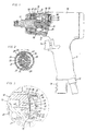
- a pneumatic power wrench comprising a housing 10 formed with a handle 11, a pressure air supply connection 12 and an exhaust deflector 13 located on the lower extreme end of the handle 11, and a throttle valve 14 for controlling the motive air supply to the wrench.
- the power wrench further comprises a pneumatic rotation motor (not shown) connected to the air supply connection 12 as well as to the exhaust deflector 13. The latter communicates with the motor via the inside area of the housing 10 which forms a part of the exhaust passage through the housing 10.
- the power wrench also comprises a hydraulic torque impulse generator 16 driven by the motor, and an output shaft 17 for delivering torque impulses to a screw joint to be tightened.
- the output shaft 17 is formed with a square end for carrying a standard type nut socket.
- the hydraulic impulse generator 16 comprises a drive member 18 which is connected to the motor and comprises a cylindrical fluid chamber 19.
- the impulse generator 16 further includes an output member 20. which is formed in one piece with the output shaft 17 and extends into the fluid chamber 19 via a central opening 21 in the front end wall 22 of the drive member 18.
- the output member 20 has a transverse cylinder bore 23 in which are movably guided two pistons 24.
- the latters are reciprocated in the cylinder bore 23 by a cam means comprising two cam lobes 26 formed on the inner wall of the fluid chamber 19 and a central cam spindle 27.
- the cam lobes 26 act on the pistons 24 via two rollers 25.
- the central cam spindle 27 is rotatively journalled in the output member 20 but rotatively locked relative to the drive member 18.
- the cam lobes 26 drive simoultaneously the two pistons 24 inwardly to, thereby, generate high pressure peaks in the cylinder bore 23 between the pistons 24.
- the torque resistance on the drive member 18 generated by the pistons 24 and rollers 25 in their engagement with the cam lobes 26 results in a momentary transfer of kinetic energy from the drive member 18 to the output member 20, thereby generating a torque impulse in the output member 20.
- the drive member 18 also comprises a rear end wall 30 which is formed with a coupling (not shown) for connection to the motor.
- the rear end wall 30 is provided with a hydraulic fluid accumulator for receiving and returning, alternatively, hydraulic fluid as the volume of the latter changes due to, for instance temperature changes.
- the volume of the hydraulic fluid increases, and the additional fluid volume is absorbed by the accumulator chamber 32.
- the accumulator chamber returns fluid to the fluid chamber 19 to compensate for the decreased fluid volume.
- the accumulator chamber 32 is formed by a depression 33 in the end wall 30 and a concentric recess 34 in a plug shaped closure 36.
- a thread connection 35 is provided to mount the latter in a cylindrical bore 37 in the end wall 30.
- an elastically deflectable membrane 39 Between a shoulder 38 in the bore 37 and the inner end of the closure 36, there is clamped an elastically deflectable membrane 39 by which the accumulator chamber 32 is divided into a first compartment 40 and a second department 42.
- the first compartment 40 is defined by the depression 33 and the membrane 39, whereas the second compartment 42 is formed by the membrane 39 and the recess 34 in the closure 36. See Fig. 3.
- the first compartment 40 communicates with the fluid chamber 19 via a passage 43
- the second compartement 42 communicates with the area outside the impulse generator 16 via openings 44 located in the bottom corners of two blind bores 45 in the closure 36.
- These blind bores 45 are intended also to form a grip means for a closure tightening tool.
- the openings 44 have the essential purpose to communicate the air pressure from inside the power wrench housing 10 to the second accumulator chamber compartment 42, thereby obtaining a resilient bias force on the membrane 39 in the direction of the first compartment 40.
- the air pressure existing in the power wrench housing 10 is the outlet pressure from the air motor.
- the membrane 39 is shown as consisting of two thinn layers, namely one layer 47 of a material having a high resistance to hydraulic fluid and a second layer 48 having favourable properties for obtaining an elastically deflectable membrane. Accordingly, the main purpose of the first membrane layer 47 is to protect the other layer 48 from being destructed by the chemically aggressive hydraulic fluid, thereby ensuring a long and safe service life of the membrane 39.
- the fluid chamber 19 remains at a substantially constant low pressure. This means that the accumulator chamber 32 and the membrane 39 are not exposed to any high pressure peaks, which even through a very much restricted communication passage would have had a deterior effect on the membrane and the operation of the accumulator device.
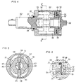
- the impulse generator shown in Figs. 4, 5 and 6 is basically of a well known type comprising a cylindrical drive member 50 intended to be connected to a rotation motor and an output member 51 coaxial with the drive member 50 and formed integral with an output shaft 52.
- the drive member 50 includes a cylindrical fluid chamber 53 in which is received the rear end of the output member 51.
- the output member 50 is also formed with longitudinally extending imovable seal ribs 57.
- the vanes 54 and the seal ribs 57 are intended to cooperate with seal lands 58 and 59, respectively, on the inner wall of the fluid chamber 53 to produce repeated high pressure peaks in the fluid chamber 53.
- a central cam spindle 60 is rotatively journalled in the output member 51 but rotatively locked relative to the drive member 50.
- the cam spindle 60 is arranged to move the vanes outwardly before each impulse to be generated so as to ensure that the vanes 54 get into their sealing contacts with the seal lands 58.
- the drive member 50 further comprises a front end wall 61 with a central opening 56 for penetration of the output member 51, and a rear end wall 62 which is provided with a stub axle 63 for connection to a rotation motor.
- the rear end wall 62 is also formed with an annular accumulator chamber 64 which is connected to the fluid chamber 53 via a passage 65.
- the accumulator chamber 64 is defined by an annular closure unit comprising a ring element 66 with an annular recess 67 and a retainer ring 68 mounted in the rear end of the drive member 50 by means of a thread connection 70. So, when mounted on the drive member 50, the retainer ring 68 presses via the thread connection 70 the ring element 66 towards the end wall 61. It also clamps the end wall 61 against a shoulder 69 in the drive member 50 so as to firmly fix the end wall 62 relative to the drive member 50.
- the accumulator chamber 64 is divided into a first annular compartment 71 and a second annular compartment 72 by an annular membrane 73.
- the first compartment 71 is connected to the fluid chamber 53 via the passage 65 which has an opening 74 communicating with the fluid chamber 53 via a clearance seal for protection of the accumulator chamber 50 and the membrane 73 against high pressure peaks.
- the opening 74 is located so as to be covered by the end surface of a vane 54 as a high pressure peak is generated in the fluid chamber 53.
- Fig, 6 there is illustrated in dash lines an alternative location of the opening 74, namely in between the end wall 61 and a shoulder 75 on the output member 51.
- the second compartment 72 of the accumulator chamber 64 is provided with a passage 76 for connection to the area outside the drive member 50 where the outlet pressure of the motor prevails. This means that the biassing force on the membrane 73 is accomplished by pressure air.
- the second accumulator compartment may be completely closed such that the air volume therein will act as a spring means and act with an elastic bias force on the membrane.
- Another alternative bias means for the membrane could be a foamed plastic or rubber material cushion inserted in the second accumulator compartment.
Landscapes
- Engineering & Computer Science (AREA)
- Mechanical Engineering (AREA)
- Details Of Spanners, Wrenches, And Screw Drivers And Accessories (AREA)
- Combined Devices Of Dampers And Springs (AREA)
- Motor Power Transmission Devices (AREA)
- Supply Devices, Intensifiers, Converters, And Telemotors (AREA)
- Percussive Tools And Related Accessories (AREA)
Claims (14)
- Hydraulischer Drehimpulserzeuger für ein Werkzeug zum Anziehen einer Schraubverbindung mit einem Antriebselement (18; 50), das mit einem Drehmotor verbunden ist und eine im wesentlichen zylindrische Fluidkammer (19; 53) mit zwei entgegengesetzten Endwänden (22, 30; 61, 62) aufweist, einem Impulse empfangenden Abtriebselement (20; 51), das koaxial zu dem Antriebselement (18; 50) liegt und sich in die Fluidkammer (19; 53) durch eine Öffnung (21; 56) in einer der Endwände (22; 61) erstreckt, hydraulische Druckspitzen erzeugenden Mitteln (23 - 27; 54 - 59), die in der Fluidkammer (19; 53) zum Erzeugen von Drehimpulsen bei relativer Rotation zwischen dem Antriebselement (18; 50) und dem Impulse empfangenden Abtriebselement (20; 51) angeordnet sind, und einer Fluidsammelkammer (32; 64) mit variablem Volumen, die in dem Antriebselement (18; 50) angeordnet und mit der Fluidkammer (19; 53) zum Ausgleich auftretender Volumenänderungen in dem hydraulischen Fluid verbunden ist, dadurch gekennzeichnet, daß die Sammelkammer (32; 64) in einer der Endwände (30; 62) angeordnet ist, eine elastisch verformbare Membran (39; 73) zum Teilen der Sammelkammer (32; 64) in einen ersten Bereich (40; 71) und einen zweiten Bereich (42; 72) vorgesehen ist, ein Fluidkanal (43; 65) den ersten Bereich (40; 71) mit der Fluidkammer (19; 53) verbindet, nachgiebige Mittel wenigstens teilweise in dem zweiten Bereich (42; 72) vorgesehen sind, um die Membran (39; 73) in Richtung des ersten Bereiches (40; 71) vorzubelasten, und eine Schließeinheit (36; 66, 68) die Sammelkammer (32; 64) teilweise begrenzt, Befestigungsmittel zum starren Anbringen an der Endwand (30; 62) aufweist und mittels eines Innenendes Haltemittel für die Membran (39; 73) bildet.
- Impulserzeuger nach Anspruch 1, dadurch gekennzeichnet, daß die Schließeinheit (36) einen zylindrischen Stopfen aufweist, der mit einer konzentrischen Ausnehmung (34) an seinem innenliegenden Ende ausgebildet ist, wobei die Ausnehmung (34) die zweite Kammer (42) bildet.
- Impulserzeuger nach Anspruch 2, dadurch gekennzeichnet, daß die Ausnehmung (34) durch eine im wesentlichen teilkugelförmige Oberfläche gebildet ist, die zur Ausbildung einer Abstützung für die Membran (39) vorgesehen ist, wenn letztere vollständig verformt ist.
- Impulserzeuger nach einem der Ansprüche 1 bis 3, dadurch gekennzeichnet, daß das Antriebselement (18) in einem Werkzeuggehäuse (10) angeordnet ist, das mit Druckluft versorgt ist, und die Schließeinheit (36) einen Luftkanal (44) besitzt, der Druckluft in den zweiten Bereich (42) zum Vorbelasten der Membran (39) einleitet.
- Impulserzeuger nach einem der Ansprüche 2 bis 4, dadurch gekennzeichnet, daß die Sammelkammer (32) eine zylindrische Bohrung (37) mit einem ringförmigen Absatz (38) aufweist und die Membran (39) zwischen dem Absatz (38) und dem Innenende der Schließeinheit (36) verklemmt ist, wenn letzere in der Bohrung (37) befestigt ist.
- Impulserzeuger nach Anspruch 5, dadurch gekennzeichnet, daß die Schließeinheit (36) in der Bohrung (37) mit Hilfe einer Gewindeverbindung (35) festgelegt ist, die zum Erzeugen einer Klemmkraft auf die Membran (39) vorgesehen ist.
- Impulserzeuger nach einem der Ansprüche 1 bis 6, dadurch gekennzeichnet, daß die Mittel zum Vorbelasten der Membran ein elastisch komprimierbares Schaumstoffelement aufweisen.
- Impulserzeuger nach einem der Ansprüche 1 bis 7, dadurch gekennzeichnet, daß die Sammelkammer (32) in einer Endwand (30) des Antriebselements (18) mit seitlichem Versatz zu der Drehachse von letzterem angeordnet ist.
- Impulserzeuger nach einem der Ansprüche 1 bis 8, dadurch gekennzeichnet, daß das Abtriebselement (20) wenigstens einen radial ausgerichteten Hochdruckzylinder (23) aufweist, der innerhalb der Fluidkammer (19) angeordnet ist und in welchem ein Kolbenelement (24) mit Hilfe eines Nockenmechanismus (25 - 27) hin und her beweglich ist, um Drehimpulse erzeugende Druckspitzen in dem Hochdruckzylinder (23) zu erzeugen, wobei die Sammelkammer (32) mit der Fluidkammer (19) außerhalb des Hochdruckzylinders (23) in Verbindung steht.
- Impulserzeuger nach Anspruch 9, dadurch gekennzeichnet, daß die Membran aus elastischem Material, wie z. B. Kunststoff oder Gummi besteht.
- Impulserzeuger nach Anspruch 1, dadurch gekennzeichnet, daß die Sammelkammer (64) eine Ringform besitzt und koaxial zu dem Antriebselement (50) angeordnet ist, wobei die Membran (73) ringförmig ist und die Schließeinheit (66, 68) ein Ringelement (66) aufweist, das mit einer ringförmigen Ausnehmung (67) ausgebildet ist, um den zweiten Bereich zu schaffen.
- Impulserzeuger nach Anspruch 11, dadurch gekennzeichnet, daß die Schließeinheit (66, 68) ein die Sammelkammer definierendes Ringelement (66) und einen Haltering (68) aufweist, der mit Hilfe einer Gewindeverbindung an dem Antriebselement (50) festgelegt ist, die zur Aufbringung einer Klemmkraft auf das Ringelement (66) vorgesehen ist.
- Impulserzeuger nach Anspruch 11 oder 12, dadurch gekennzeichnet, daß der Fluidkanal (65) den ersten Bereich (71) der Sammelkammer (64) mit der Fluidkammer (53) über eine Öffnung (74) in letzterer verbindet, die vor Hochdruckspitzen in der Fluidkammer (53) durch eine Durchflußbegrenzung geschützt ist, die durch ein enges Spiel zwischen dem Antriebselement (50) und dem Abtriebselement (51) ausgebildet ist.
- Impulserzeuger nach einem der Ansprüche 11 bis 13, dadurch gekennzeichnet, daß die hydraulische Druckspitzen erzeugenden Mittel (54 - 59) wenigstens einen Flügel (54) aufweisen, die jeweils gleitend in einem Radialschlitz (55) in dem Abtriebselement (51) zum Zusammenwirken mit Dichtvorsprüngen (58) an dem Antriebselement (50) in der Fluidkammer (53) abgestützt sind.
Applications Claiming Priority (2)
| Application Number | Priority Date | Filing Date | Title |
|---|---|---|---|
| SE9702190 | 1997-06-09 | ||
| SE9702190A SE509915C2 (sv) | 1997-06-09 | 1997-06-09 | Hydraulisk momentimpulsgeneratoror |
Publications (3)
| Publication Number | Publication Date |
|---|---|
| EP0885693A2 EP0885693A2 (de) | 1998-12-23 |
| EP0885693A3 EP0885693A3 (de) | 2000-05-10 |
| EP0885693B1 true EP0885693B1 (de) | 2002-08-07 |
Family
ID=20407301
Family Applications (1)
| Application Number | Title | Priority Date | Filing Date |
|---|---|---|---|
| EP98850089A Expired - Lifetime EP0885693B1 (de) | 1997-06-09 | 1998-05-28 | Hydraulischer Drehmoment-Impuls-Erzeuger |
Country Status (5)
| Country | Link |
|---|---|
| US (1) | US6110045A (de) |
| EP (1) | EP0885693B1 (de) |
| JP (1) | JP4217297B2 (de) |
| DE (1) | DE69807013T2 (de) |
| SE (1) | SE509915C2 (de) |
Cited By (3)
| Publication number | Priority date | Publication date | Assignee | Title |
|---|---|---|---|---|
| US6938526B2 (en) | 2003-07-30 | 2005-09-06 | Black & Decker Inc. | Impact wrench having an improved anvil to square driver transition |
| US7036406B2 (en) | 2003-07-30 | 2006-05-02 | Black & Decker Inc. | Impact wrench having an improved anvil to square driver transition |
| WO2014198679A2 (en) | 2013-06-12 | 2014-12-18 | Atlas Copco Industrial Technique Ab | A method for diagnosing a torque impulse generator |
Families Citing this family (24)
| Publication number | Priority date | Publication date | Assignee | Title |
|---|---|---|---|---|
| JP3615125B2 (ja) * | 2000-03-30 | 2005-01-26 | 株式会社マキタ | オイルユニット及び電動工具 |
| JP2002361570A (ja) * | 2001-06-06 | 2002-12-18 | Uryu Seisaku Ltd | 油圧式トルクレンチの打撃トルク発生装置 |
| SE525600C2 (sv) * | 2002-08-29 | 2005-03-15 | Atlas Copco Rock Drills Ab | Ackumulator för vätskedrivet slagverk med en kropp av skumplast |
| TWM257933U (en) * | 2004-05-13 | 2005-03-01 | Chu Dai Ind Co Ltd | Leaking air pressure for a pneumatic tool |
| US7249638B2 (en) | 2005-01-07 | 2007-07-31 | Black & Decker Inc. | Impact wrench anvil and method of forming an impact wrench anvil |
| ATE452731T1 (de) * | 2006-11-13 | 2010-01-15 | Cooper Power Tools Gmbh & Co | Werkzeug mit einem hydraulikschlagwerk |
| US8333143B2 (en) * | 2009-07-31 | 2012-12-18 | Yu-Hui Liao | Hydraulic cylinder device |
| SE535186C2 (sv) | 2010-05-12 | 2012-05-15 | Atlas Copco Tools Ab | Mutterdragare med hydraulisk pulsenhet |
| JP5561076B2 (ja) * | 2010-09-30 | 2014-07-30 | 日立工機株式会社 | オイルパルス工具 |
| DE102010043099A1 (de) * | 2010-10-29 | 2012-05-03 | Robert Bosch Gmbh | Handwerkzeugmaschine mit einem mechanischen Schlagwerk |
| US9604355B2 (en) * | 2011-09-30 | 2017-03-28 | Textron Innovations Inc. | Handle for a hydraulically driven tool with heat transmission reducing properties |
| JP5988821B2 (ja) * | 2012-10-17 | 2016-09-07 | 日東工器株式会社 | オイル回転衝撃力発生装置 |
| JP6027388B2 (ja) * | 2012-10-17 | 2016-11-16 | 日東工器株式会社 | オイル回転衝撃力発生装置 |
| US9878435B2 (en) | 2013-06-12 | 2018-01-30 | Makita Corporation | Power rotary tool and impact power tool |
| TW201406501A (zh) * | 2013-10-31 | 2014-02-16 | Quan-Zheng He | 氣動工具的衝擊組 |
| TWM562747U (zh) | 2016-08-25 | 2018-07-01 | 米沃奇電子工具公司 | 衝擊工具 |
| US11759926B2 (en) * | 2017-05-16 | 2023-09-19 | Atlas Copco Industrial Technique Ab | Oil level warning at hydraulic impulse wrenches |
| SE542994C2 (en) * | 2018-09-10 | 2020-09-22 | Atlas Copco Ind Technique Ab | POWER WRENCH COMPRISING A HYDRAULIC PULSE UNIT WITH A SEPARATING ARRANGEMENT FOR EXTRACTING AIR FROM OIL |
| US12325112B2 (en) * | 2020-09-28 | 2025-06-10 | Milwaukee Electric Tool Corporation | Power tool with impulse assembly including a valve |
| SE544938C2 (en) | 2021-11-29 | 2023-01-10 | Atlas Copco Ind Technique Ab | Power tool comprising a hydraulic pulse unit |
| US12447588B2 (en) | 2021-12-17 | 2025-10-21 | Black & Decker Inc. | Impact driver |
| SE2230372A1 (en) * | 2022-11-17 | 2024-01-09 | Atlas Copco Ind Technique Ab | Power tool comprising a hydraulic pulse unit |
| TWI840008B (zh) * | 2022-12-12 | 2024-04-21 | 台灣保來得股份有限公司 | 傳動機構 |
| SE2330204A1 (en) | 2023-05-05 | 2024-10-29 | Atlas Copco Ind Technique Ab | Power tool comprising a pulse unit |
Family Cites Families (23)
| Publication number | Priority date | Publication date | Assignee | Title |
|---|---|---|---|---|
| US3116617A (en) * | 1961-12-12 | 1964-01-07 | Ingersoll Rand Co | Fluid impulse torque tool |
| US3181672A (en) * | 1961-06-20 | 1965-05-04 | Gardner Denver Co | Tension control wrench |
| US3174606A (en) * | 1962-12-20 | 1965-03-23 | Ingersoll Rand Co | Torque control for driving means |
| US3214940A (en) * | 1963-01-08 | 1965-11-02 | Thor Power Tool Co | Impulse tool |
| US3199314A (en) * | 1963-04-08 | 1965-08-10 | Ingersoll Rand Co | Torque control device |
| US3182470A (en) * | 1963-04-08 | 1965-05-11 | Ingersoll Rand Co | Sealing device |
| US3289407A (en) * | 1963-05-17 | 1966-12-06 | Ingersoll Rand Co | Torque device |
| US3319723A (en) * | 1965-04-01 | 1967-05-16 | Ingersoll Rand Co | Axial piston pulse generator |
| US3292391A (en) * | 1965-04-01 | 1966-12-20 | Ingersoll Rand Co | Bypass control device for an impulse tool |
| US3903972A (en) * | 1974-04-24 | 1975-09-09 | Hydroacoustic Inc | Impact tools |
| US4175408A (en) * | 1976-12-10 | 1979-11-27 | Honda Giken Kogyo Kabushiki Kaisha | Apparatus for absorbing oil pressure in an impact type tool |
| SE432071B (sv) * | 1982-09-24 | 1984-03-19 | Atlas Copco Ab | Hydraulisk impulsmutterdragare |
| SE459327B (sv) * | 1984-12-21 | 1989-06-26 | Atlas Copco Ab | Hydrauliskt momentimpulsverk |
| SE446070B (sv) * | 1984-12-21 | 1986-08-11 | Atlas Copco Ab | Hydrauliskt momentimpulsverk for vridmomentalstrande verktyg |
| SE451186B (sv) * | 1986-01-23 | 1987-09-14 | Atlas Copco Ab | Hydrauliskt momentimpulsverktyg |
| JPS6327266U (de) * | 1986-07-30 | 1988-02-23 | ||
| US5217079A (en) * | 1987-05-05 | 1993-06-08 | Cooper Industries, Inc. | Hydro-impulse screwing device |
| US4838133A (en) * | 1987-09-29 | 1989-06-13 | Nippon Pneumatic Manufacturing Co., Ltd. | Hydraulic pulse wrench |
| US5092410A (en) * | 1990-03-29 | 1992-03-03 | Chicago Pneumatic Tool Company | Adjustable pressure dual piston impulse clutch |
| JP3378029B2 (ja) * | 1991-08-08 | 2003-02-17 | 丸善工業株式会社 | 油圧ブレーカ |
| SE504102C2 (sv) * | 1994-12-30 | 1996-11-11 | Atlas Copco Tools Ab | Hydraulisk momentimpulsmekanism avsedd för ett momentavgivande verktyg |
| EP0759340B1 (de) * | 1995-08-17 | 2000-05-10 | Cooper Industries, Inc. | Impulswerkzeug |
| US5611404A (en) * | 1995-09-28 | 1997-03-18 | Gpx Corp. | Hydraulic impulse tool with enhanced fluid seal |
-
1997
- 1997-06-09 SE SE9702190A patent/SE509915C2/sv not_active IP Right Cessation
-
1998
- 1998-05-28 DE DE69807013T patent/DE69807013T2/de not_active Expired - Lifetime
- 1998-05-28 EP EP98850089A patent/EP0885693B1/de not_active Expired - Lifetime
- 1998-06-03 US US09/090,050 patent/US6110045A/en not_active Expired - Lifetime
- 1998-06-09 JP JP16092298A patent/JP4217297B2/ja not_active Expired - Lifetime
Cited By (4)
| Publication number | Priority date | Publication date | Assignee | Title |
|---|---|---|---|---|
| US6938526B2 (en) | 2003-07-30 | 2005-09-06 | Black & Decker Inc. | Impact wrench having an improved anvil to square driver transition |
| US7036406B2 (en) | 2003-07-30 | 2006-05-02 | Black & Decker Inc. | Impact wrench having an improved anvil to square driver transition |
| WO2014198679A2 (en) | 2013-06-12 | 2014-12-18 | Atlas Copco Industrial Technique Ab | A method for diagnosing a torque impulse generator |
| US9983044B2 (en) | 2013-06-12 | 2018-05-29 | Atlas Copco Industrial Technique Ab | Method for diagnosing a torque impulse generator |
Also Published As
| Publication number | Publication date |
|---|---|
| JPH1190849A (ja) | 1999-04-06 |
| EP0885693A3 (de) | 2000-05-10 |
| SE509915C2 (sv) | 1999-03-22 |
| SE9702190D0 (sv) | 1997-06-09 |
| DE69807013D1 (de) | 2002-09-12 |
| DE69807013T2 (de) | 2003-05-08 |
| JP4217297B2 (ja) | 2009-01-28 |
| EP0885693A2 (de) | 1998-12-23 |
| US6110045A (en) | 2000-08-29 |
| SE9702190L (sv) | 1998-12-10 |
Similar Documents
| Publication | Publication Date | Title |
|---|---|---|
| EP0885693B1 (de) | Hydraulischer Drehmoment-Impuls-Erzeuger | |
| US5544710A (en) | Pulse tool | |
| EP0105038B1 (de) | Hydraulisches Drehschlagwerkzeug | |
| US3896845A (en) | Accumulator charging and relief valve | |
| US6863134B2 (en) | Rotary tool | |
| CA2211474A1 (en) | Pressure intensifier for fluids, particularly for hydraulic liquids | |
| EP0719618B1 (de) | Hydraulischer Drehschlagmechanismus | |
| WO2000071303A2 (en) | Impulse wrench | |
| AU2003299403A1 (en) | Control valve with improved sealing for a fluid circulation system | |
| GB2284023A (en) | A fluid-actuated motor | |
| US3687008A (en) | Pressure fluid controlled reciprocating mechanism | |
| AU635458B2 (en) | High efficiency pneumatic motor | |
| AU8516598A (en) | Hydraulic system and pump | |
| EP0290411B1 (de) | Hydraulischer Drehmomentimpuls-Erzeuger | |
| EP0721823B1 (de) | Hydraulischer Drehschlagmechanismus | |
| US4924670A (en) | Hydraulic unit for a motor vehicle | |
| EP0235102B1 (de) | Hydraulischer Drehmomentimpulserzeuger | |
| EP2358518A1 (de) | Ausrüstung mit einem wählventil zum reparieren und aufblasen von aufblasbaren artikeln | |
| EP0787905A3 (de) | Einheit zur Verteilung eines Druckmediums | |
| EP0665087B1 (de) | Hydraulischer Drehmomentimpuls-Erzeuger | |
| US6823949B2 (en) | Modular control apparatus for a power impact tool | |
| KR100422093B1 (ko) | 피스톤 행정거리 변환장치를 구비한 유압타격장치 | |
| US3717011A (en) | Impulse unit | |
| CN217620416U (zh) | 一种强力风扳捶打装置 | |
| CA2185763A1 (en) | A slack adjustable force transmitting cylinder |
Legal Events
| Date | Code | Title | Description |
|---|---|---|---|
| PUAI | Public reference made under article 153(3) epc to a published international application that has entered the european phase |
Free format text: ORIGINAL CODE: 0009012 |
|
| AK | Designated contracting states |
Kind code of ref document: A2 Designated state(s): DE FR GB IT |
|
| AX | Request for extension of the european patent |
Free format text: AL;LT;LV;MK;RO;SI |
|
| PUAL | Search report despatched |
Free format text: ORIGINAL CODE: 0009013 |
|
| AK | Designated contracting states |
Kind code of ref document: A3 Designated state(s): AT BE CH CY DE DK ES FI FR GB GR IE IT LI LU MC NL PT SE |
|
| AX | Request for extension of the european patent |
Free format text: AL;LT;LV;MK;RO;SI |
|
| 17P | Request for examination filed |
Effective date: 20001020 |
|
| AKX | Designation fees paid |
Free format text: DE FR GB IT |
|
| GRAG | Despatch of communication of intention to grant |
Free format text: ORIGINAL CODE: EPIDOS AGRA |
|
| 17Q | First examination report despatched |
Effective date: 20010706 |
|
| GRAG | Despatch of communication of intention to grant |
Free format text: ORIGINAL CODE: EPIDOS AGRA |
|
| GRAH | Despatch of communication of intention to grant a patent |
Free format text: ORIGINAL CODE: EPIDOS IGRA |
|
| GRAH | Despatch of communication of intention to grant a patent |
Free format text: ORIGINAL CODE: EPIDOS IGRA |
|
| GRAA | (expected) grant |
Free format text: ORIGINAL CODE: 0009210 |
|
| AK | Designated contracting states |
Kind code of ref document: B1 Designated state(s): DE FR GB IT |
|
| REG | Reference to a national code |
Ref country code: GB Ref legal event code: FG4D |
|
| REF | Corresponds to: |
Ref document number: 69807013 Country of ref document: DE Date of ref document: 20020912 |
|
| ET | Fr: translation filed | ||
| PLBE | No opposition filed within time limit |
Free format text: ORIGINAL CODE: 0009261 |
|
| STAA | Information on the status of an ep patent application or granted ep patent |
Free format text: STATUS: NO OPPOSITION FILED WITHIN TIME LIMIT |
|
| 26N | No opposition filed |
Effective date: 20030508 |
|
| REG | Reference to a national code |
Ref country code: DE Ref legal event code: R082 Ref document number: 69807013 Country of ref document: DE Representative=s name: PATENTANWAELTE OLBRICHT, BUCHHOLD, KEULERTZ PA, DE |
|
| REG | Reference to a national code |
Ref country code: FR Ref legal event code: PLFP Year of fee payment: 19 |
|
| REG | Reference to a national code |
Ref country code: FR Ref legal event code: PLFP Year of fee payment: 20 |
|
| PGFP | Annual fee paid to national office [announced via postgrant information from national office to epo] |
Ref country code: GB Payment date: 20170530 Year of fee payment: 20 Ref country code: DE Payment date: 20170530 Year of fee payment: 20 Ref country code: FR Payment date: 20170525 Year of fee payment: 20 |
|
| PGFP | Annual fee paid to national office [announced via postgrant information from national office to epo] |
Ref country code: IT Payment date: 20170524 Year of fee payment: 20 |
|
| REG | Reference to a national code |
Ref country code: DE Ref legal event code: R071 Ref document number: 69807013 Country of ref document: DE |
|
| REG | Reference to a national code |
Ref country code: GB Ref legal event code: PE20 Expiry date: 20180527 |
|
| PG25 | Lapsed in a contracting state [announced via postgrant information from national office to epo] |
Ref country code: GB Free format text: LAPSE BECAUSE OF EXPIRATION OF PROTECTION Effective date: 20180527 |