EP0885678A2 - Face milling cutter - Google Patents
Face milling cutter Download PDFInfo
- Publication number
- EP0885678A2 EP0885678A2 EP98850078A EP98850078A EP0885678A2 EP 0885678 A2 EP0885678 A2 EP 0885678A2 EP 98850078 A EP98850078 A EP 98850078A EP 98850078 A EP98850078 A EP 98850078A EP 0885678 A2 EP0885678 A2 EP 0885678A2
- Authority
- EP
- European Patent Office
- Prior art keywords
- cutting
- cutting insert
- insert
- holder
- shim
- Prior art date
- Legal status (The legal status is an assumption and is not a legal conclusion. Google has not performed a legal analysis and makes no representation as to the accuracy of the status listed.)
- Granted
Links
Images


Classifications
-
- B—PERFORMING OPERATIONS; TRANSPORTING
- B23—MACHINE TOOLS; METAL-WORKING NOT OTHERWISE PROVIDED FOR
- B23C—MILLING
- B23C5/00—Milling-cutters
- B23C5/16—Milling-cutters characterised by physical features other than shape
- B23C5/20—Milling-cutters characterised by physical features other than shape with removable cutter bits or teeth or cutting inserts
- B23C5/22—Securing arrangements for bits or teeth or cutting inserts
- B23C5/2204—Securing arrangements for bits or teeth or cutting inserts with cutting inserts clamped against the walls of the recess in the cutter body by a clamping member acting upon the wall of a hole in the insert
- B23C5/2208—Securing arrangements for bits or teeth or cutting inserts with cutting inserts clamped against the walls of the recess in the cutter body by a clamping member acting upon the wall of a hole in the insert for plate-like cutting inserts
- B23C5/2213—Securing arrangements for bits or teeth or cutting inserts with cutting inserts clamped against the walls of the recess in the cutter body by a clamping member acting upon the wall of a hole in the insert for plate-like cutting inserts having a special shape
-
- B—PERFORMING OPERATIONS; TRANSPORTING
- B23—MACHINE TOOLS; METAL-WORKING NOT OTHERWISE PROVIDED FOR
- B23C—MILLING
- B23C2200/00—Details of milling cutting inserts
- B23C2200/08—Rake or top surfaces
- B23C2200/085—Rake or top surfaces discontinuous
-
- B—PERFORMING OPERATIONS; TRANSPORTING
- B23—MACHINE TOOLS; METAL-WORKING NOT OTHERWISE PROVIDED FOR
- B23C—MILLING
- B23C2200/00—Details of milling cutting inserts
- B23C2200/12—Side or flank surfaces
- B23C2200/125—Side or flank surfaces discontinuous
-
- B—PERFORMING OPERATIONS; TRANSPORTING
- B23—MACHINE TOOLS; METAL-WORKING NOT OTHERWISE PROVIDED FOR
- B23C—MILLING
- B23C2200/00—Details of milling cutting inserts
- B23C2200/20—Top or side views of the cutting edge
- B23C2200/205—Discontinuous cutting edges
-
- B—PERFORMING OPERATIONS; TRANSPORTING
- B23—MACHINE TOOLS; METAL-WORKING NOT OTHERWISE PROVIDED FOR
- B23C—MILLING
- B23C2200/00—Details of milling cutting inserts
- B23C2200/36—Other features of the milling insert not covered by B23C2200/04 - B23C2200/32
- B23C2200/367—Mounted tangentially, i.e. where the rake face is not the face with largest area
-
- Y—GENERAL TAGGING OF NEW TECHNOLOGICAL DEVELOPMENTS; GENERAL TAGGING OF CROSS-SECTIONAL TECHNOLOGIES SPANNING OVER SEVERAL SECTIONS OF THE IPC; TECHNICAL SUBJECTS COVERED BY FORMER USPC CROSS-REFERENCE ART COLLECTIONS [XRACs] AND DIGESTS
- Y10—TECHNICAL SUBJECTS COVERED BY FORMER USPC
- Y10T—TECHNICAL SUBJECTS COVERED BY FORMER US CLASSIFICATION
- Y10T407/00—Cutters, for shaping
- Y10T407/19—Rotary cutting tool
- Y10T407/1906—Rotary cutting tool including holder [i.e., head] having seat for inserted tool
- Y10T407/1908—Face or end mill
- Y10T407/1912—Tool adjustable relative to holder
-
- Y—GENERAL TAGGING OF NEW TECHNOLOGICAL DEVELOPMENTS; GENERAL TAGGING OF CROSS-SECTIONAL TECHNOLOGIES SPANNING OVER SEVERAL SECTIONS OF THE IPC; TECHNICAL SUBJECTS COVERED BY FORMER USPC CROSS-REFERENCE ART COLLECTIONS [XRACs] AND DIGESTS
- Y10—TECHNICAL SUBJECTS COVERED BY FORMER USPC
- Y10T—TECHNICAL SUBJECTS COVERED BY FORMER US CLASSIFICATION
- Y10T407/00—Cutters, for shaping
- Y10T407/19—Rotary cutting tool
- Y10T407/1906—Rotary cutting tool including holder [i.e., head] having seat for inserted tool
- Y10T407/1908—Face or end mill
- Y10T407/1912—Tool adjustable relative to holder
- Y10T407/1914—Radially
- Y10T407/1916—And axially
-
- Y—GENERAL TAGGING OF NEW TECHNOLOGICAL DEVELOPMENTS; GENERAL TAGGING OF CROSS-SECTIONAL TECHNOLOGIES SPANNING OVER SEVERAL SECTIONS OF THE IPC; TECHNICAL SUBJECTS COVERED BY FORMER USPC CROSS-REFERENCE ART COLLECTIONS [XRACs] AND DIGESTS
- Y10—TECHNICAL SUBJECTS COVERED BY FORMER USPC
- Y10T—TECHNICAL SUBJECTS COVERED BY FORMER US CLASSIFICATION
- Y10T407/00—Cutters, for shaping
- Y10T407/19—Rotary cutting tool
- Y10T407/1906—Rotary cutting tool including holder [i.e., head] having seat for inserted tool
- Y10T407/1928—Tool adjustable relative to holder
-
- Y—GENERAL TAGGING OF NEW TECHNOLOGICAL DEVELOPMENTS; GENERAL TAGGING OF CROSS-SECTIONAL TECHNOLOGIES SPANNING OVER SEVERAL SECTIONS OF THE IPC; TECHNICAL SUBJECTS COVERED BY FORMER USPC CROSS-REFERENCE ART COLLECTIONS [XRACs] AND DIGESTS
- Y10—TECHNICAL SUBJECTS COVERED BY FORMER USPC
- Y10T—TECHNICAL SUBJECTS COVERED BY FORMER US CLASSIFICATION
- Y10T407/00—Cutters, for shaping
- Y10T407/19—Rotary cutting tool
- Y10T407/1906—Rotary cutting tool including holder [i.e., head] having seat for inserted tool
- Y10T407/1934—Rotary cutting tool including holder [i.e., head] having seat for inserted tool with separate means to fasten tool to holder
-
- Y—GENERAL TAGGING OF NEW TECHNOLOGICAL DEVELOPMENTS; GENERAL TAGGING OF CROSS-SECTIONAL TECHNOLOGIES SPANNING OVER SEVERAL SECTIONS OF THE IPC; TECHNICAL SUBJECTS COVERED BY FORMER USPC CROSS-REFERENCE ART COLLECTIONS [XRACs] AND DIGESTS
- Y10—TECHNICAL SUBJECTS COVERED BY FORMER USPC
- Y10T—TECHNICAL SUBJECTS COVERED BY FORMER US CLASSIFICATION
- Y10T407/00—Cutters, for shaping
- Y10T407/23—Cutters, for shaping including tool having plural alternatively usable cutting edges
Definitions
- the present invention relates to a face milling cutter including a holder, which can be fastened at the end surface of a rotatable spindle, a number of first and second cutting inserts, each having at least one cutting edge and being releaseably attached to the end surface of said holder at a radial distance from the axis of the spindle, said cutting edges extending outwardly from the end surface of said holder, such that said cutting edges freely can come into engagement with and machine a surface of a work piece, means for releaseably securing said cutting insert at said holder by means of a central opening in said cutting insert, said cutting inserts being peripherally distributed around said holder, said first cutting insert comprising cutting edges directed substantially in the axial direction and said second cutting insert comprising cutting edges directed substantially in the radial direction.
- the invention further relates to a shim for the tool, a method for determining the axial position of cutting inserts provided in a face milling cutter as well as a milling insert.
- One object of the present invention is to provide a face milling cutter having simply adjustable wiper inserts.
- Another object of the present invention is to provide a quick and precise method for determining the axial position of cutting inserts provided in a face milling cutter.
- Still another object of the present invention is to provide a milling insert, which saves four cutting corners for further use in adjacent cutting insert pockets.
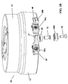
- Fig. 1A shows a face milling cutter according to the present invention, in a perspective view
- Fig. 1B shows a face milling cutter according to the present invention, partly in an exploded view
- Figs. 2 and 3 show parts of the tool shown in Fig. 1A, in a perspective view
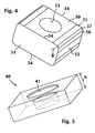
- Fig. 4 shows a perspective view of a cutting insert according to the present invention for the tool
- Fig. 5 shows a perspective view of a shim for the tool according to the present invention.
- Figs. 1A, 1B 2 and 3 show the face milling cutter 10 according to the present invention which comprises a holder or body 11 which shall be mounted to a spindle, not shown.
- the holder has an edge portion 12 with an essentially cylindrical jacket surface 15, a ring-shaped end surface 13, and a central hole 14.
- a number of first and second pockets 16 and 17 are provided in the area of intersection between the envelope surface 15 and the ring-shaped surface 13, each of which are provided to hold a cutting insert 18A and 18B. It is understood that further pockets and cutting inserts than shown are arranged at the tool.
- Each first pocket 16 (Fig. 2) consists of a recess in the body 11 and forms a radial support surface 19, an axial support surface 20 and a tangential support surface 21.
- the radial support surface 19 is provided to transfer radial cutting forces from the cutting insert 18A during the milling operation.
- the axial support surface 20 is provided to transfer axial cutting forces from the cutting insert 18A.
- the tangential support surface 21 is provided to transfer tangential cutting forces from the cutting insert 18A.
- Each second pocket 17 (Fig. 3) consists of a recess in the body 11 and forms a radial support surface 22, an axial support surface 23 and a tangential support surface 24.
- the function of the support surfaces 22-24 is the same as explained above in connection with the support surfaces 19-21.
- the first and second pockets 16 and 17 are provided to receive cutting inserts 18A and 18B, which are inclined about 90° relative to each other.
- the cutting inserts 18A are tangentially mounted with central threaded holes directed substantially towards the axis of rotation CL of the milling cutter and that the cutting inserts 18B are end mounted with central threaded holes directed substantially parallel with the axis of rotation of the milling cutter. Every other cutting insert in the tool's periphery defines a second cutting insert 18B and the remaining cutting inserts constitute the first cutting inserts 18A.
- the pockets may be evenly or unevenly distributed round the periphery of the body. Immediately in front of each pocket 16 and 17 is provided a chip space 27 and 28.
- the cutting insert according to Fig. 4 for example can be made of a cutting tool material available on the market today, wherein tungsten carbide is a preferred material
- the insert is preferably manufactured by grinding.
- the face milling cutter has first 18A and second cutting inserts 18B, which are identically square and comprise substantially planar parallel side faces 50, substantially planar parallel first side surfaces 51, substantially planar parallel second side surfaces 52 and the central opening 53.
- Four cutting edges 54 are provided in lines of intersection between said surfaces 50,51,52.
- the cutting edge 54 which lies in the plane of the connected first edge surface 51, is defined at the transition between the side surface 50 and the second edge surface 52, at least partly by a planar or curved first chamfer 57.
- the chamfer 57 is surrounded by two substantially planar second chamfers 55, 56 symmetrically arranged about a bisector B of the cutting corner.
- the cutting edge at the chamfer 55 of the first cutting insert 18A and the cutting edge of the second chamfer 56 of the second cutting insert 18B are active. This division of work between adjacent cutting insert requires that the cutting inserts shall be able to be exactly adjusted relative to each other, which can be done with the aid of the shim 40.
- the size of the cutting inserts is generally based on the feed per revolution for full utilization of the available cutting edge.
- the cutting inserts 18A and 18B are identical, which makes confusion of these impossible in connection with mounting of cutting inserts in the milling tool.
- the tool is provided such that the worn cutting inserts 18A can be transferred to the pockets 17 while the worn the cutting inserts 18B can be transferred to the pockets 16 for presenting fresh edges. This can be done due to that only four cutting corners of eight of each cutting insert wear out in each pocket.
- the major cutting edge of the first cutting insert 18A projects radially just as far as the radially extreme part of the cutting edge of the second cutting insert 18B.
- the cutting inserts may alternatively have other basic shapes and sizes, such as rectangular or triangular.
- each screw 30 is fastened in a hollow fastening screw 31 tightened into the pocket 17.
- the fastening screw has a collar which is intended to abut against a corresponding shoulder of the hole 41 in the shim 40.
- Each cutting insert 18A is positioned with a clearance angle in relation to the workpiece surface. This angle is usually less than 15° and is preferably in the magnitude of 7°.
- a shim 40 according to Fig. 5, is provided to be fitted into in each pocket 17 for an end mounted cutting insert 18B.
- the shim is substantially polygonal and preferably square.
- the shim has a centrally positioned hole provided to receive the fastening screw 31.
- the biggest surface of the shim 40 is somewhat less than the corresponding side of the cutting insert 18B.
- the thickness h of the shim is in the magnitude of at least 50 % of the thickness of the cutting insert 18B. Shims 40 of different thicknesses shall be accessible at assembling of the mill.
- the thickness is chosen in the interval 5 of ⁇ m more or less at a level of about 4 mm.
- the total number of shims 40 to choose among, is in the magnitude of 8-15, preferably about 11. Stated another way the interval is about 4 mm ⁇ X * 5 ⁇ m, where X is integers of 0 to 7.
- the mill 10 is mounted as follows, reference being had primarily to Fig. 1B.
- the first cutting insert 18A is mounted first, by pushing one of its planar sides by hand into the pocket 16 against the radial support surface 19 and against the support surfaces 20 and 21, whereafter the screw 29 is inserted into the hole of the cutting insert and is threaded into in the threaded hole 25. Thereby the cutting insert 18A will be forced both against the radial support surface 19 and against the support surfaces 20 and 21 since the center axis of the boring is provided closer to the support surfaces 20,21 than to the center of the threaded hole.
- the fastening screw 31 is first brought through the central hole 41 of the shim 40.
- the shim is brought to abutment against the axial support surface 23 in the pocket 17 simultaneously as the fastening screw is tightened.
- the shim 40 may in that position project somewhat from the envelope surface 15 in the radial direction of the milling body.
- one planar side of the cutting insert is pushed into in the pocket 17 against the shim 40 and against the support surfaces 22 and 24, whereafter the screw 30 is inserted into the hole of the cutting insert and is threaded into in the threaded boring of the fastening screw.
- the cutting insert is forced partly against the shim 40 and partly against the support surfaces 22 and 24 by having the center axis of the boring provided closer to the support surfaces 22,24 than to the center of the threaded hole.
- the position of for example the second chamfer 55 of the cutting insert 18B is then measured in relation to the cutting insert 18A and if the position of the cutting insert 18B is about 0.04 mm below the position of the cutting insert 18A the adjustment is ideal for the second cutting inserts 18B to generate the surface.
- the positioned cutting insert 18B then constitutes a reference for the following adjustments of the cutting inserts 18B. If a cutting insert due to manufacturing tolerances of the holder differ too much from the reference value, this can be attended by choosing another shim with a more suitable thickness. When a face milling cutter once is calibrated it is sufficient just to swap cutting inserts 18A, 18B if these have worn out and yet retain the fine position.
- the method comprises in other words the following steps:- arrange a number of shims, everyone being smaller in the thickness direction and width direction than the associated cutting insert 18B, said thickness h of the shim 40 being chosen from a set up of several shims which difference in thickness is in steps of about 5 ⁇ m,- tangentially mount a first cutting insert (18A), - end mount a shim with a known thickness,- end mount a second cutting insert (18B) against the shim (40) and compare the position with that of the first cutting insert (18A),- screw the second cutting insert (18B) firmly against the shim wherein the thickness (h) of the shim determines the major cutting edge position of the second cutting insert relative to the first cutting insert (18A),- exchange shim to a shim with a suitable thickness if that axial value does not correspond to the desired position,- repeat the above-captioned steps until the tool is wholly provided with cutting inserts.
Landscapes
- Engineering & Computer Science (AREA)
- Mechanical Engineering (AREA)
- Milling Processes (AREA)
Abstract
Description
Fig. 1A shows a face milling cutter according to the present invention, in a perspective view; Fig. 1B shows a face milling cutter according to the present invention, partly in an exploded view; Figs. 2 and 3 show parts of the tool shown in Fig. 1A, in a perspective view; Fig. 4 shows a perspective view of a cutting insert according to the present invention for the tool and Fig. 5 shows a perspective view of a shim for the tool according to the present invention.
Claims (9)
- Face milling cutter comprising a holder (11), which can be secured at the end surface of a rotatable spindle, a number of cutting inserts (18A,18B), every of which having at least a major cutting edge and a secondary cutting edge and being releaseably attached to said holder at a radial distance from the axis of rotation (CL) of the cutter, said cutting edges extending outwardly of the envelope surface (15) and the end surface (13) of said holder respectively, wherein means (29,30) are provided for releaseably securing said cutting insert at said holder by means of a central opening in said cutting insert, said cutting inserts being peripherally distributed around said holder (10), said tool comprising first cutting inserts (18A) the major cutting edges of which being essentially axially directed and second cutting inserts (18B), the major cutting edges of which being essentially radially directed relative to the holder (11), said second cutting inserts (18B) being provided substantially to generate a planar surface on the work piece, said second cutting insert (18B) having width and a thickness,
characterized in that each second cutting insert (18B) rests on a shim (40), which at least in the width direction is smaller than the associated cutting insert (18B), and in that the thickness (h) of the shim is provided to determine the axial position of the major cutting edge of the second cutting insert relative to the first cutting insert (18A). - Face milling cutter according to claim 1, wherein every other cutting insert in the cutter periphery is a second cutting insert (18B) and wherein the thickness of the shim (40) is smaller than the thickness of the associated cutting insert (18B) and wherein the thickness (h) of the shim is chosen from the interval about 4 mm ± X * 5 µm, where X is integers of 0 to 7.
- Face milling cutter according to claims 1 or 2, wherein the shim (40) is provided to be fastened by a first means (31) which is provided to be fastened in a hole (26) in an axial support surface (23) of the holder, said support surface being essentially parallel with or somewhat inclined relative to the end surface (13).
- Face milling cutter according to claims 1, 2 or 3, wherein the major cutting edge of the first cutting insert (18A) projects just as far as the radially extreme part of the cutting edge of the second cutting insert (18B).
- Face milling cutter according to anyone of the preceding claims, wherein the first and the second cutting inserts (18A,18B) are identical and comprise substantially plane-parallel side faces (50), substantially plane-parallel first side surfaces (51), substantially plane-parallel second side surfaces (52) and the central opening (53), wherein four cutting edges (54) are provided at lines of intersection between said surfaces (50,51,52) and wherein the cutting edge (54) in the transition between the side surface (50) and the second side surface (52) is described by a first chamfer (57).
- Face milling cutter according to anyone of the preceding claims, wherein the threaded hole (25,26) in the axial support surface is placed such that when mounting a cutting insert by screwing a screw (29, 30) the cutting insert is forced in direction towards all said support surfaces in the pocket.
- Method to determine the axial position of a cutting insert provided in a face milling cutter, said face milling cutter comprising a holder (11), which can be secured at the end surface of a rotatable spindle, said face milling cutter will include a number of cutting inserts (18A,18B), every other of which has at least one major cutting edge and one secondary cutting edge and can be releaseably secured to said holder at a radial distance from the axis of rotation (CL) of the cutter, said cutting edges shall extend outwardly from the envelope surface (15) and the end surface (13) of said holder, wherein means (29,30) will be provided for releaseable fastening of said cutting insert at said holder by means of a central opening in said cutting insert, said cutting inserts shall be distributed peripherally around said holder (10), said tool will include first cutting inserts (18A) the major cutting edges of which are essentially axially directed and second cutting inserts (18B), the major cutting edges of which are essentially radially directed relative to the holder (11), said second cutting inserts (18B) shall substantially generate a planar surface on the work piece, characterized in that the method comprises the following steps:arrange a number of shims, which everyone is smaller than an associated cutting insert (18B) in the thickness direction and the width direction, wherein the thickness (h) of the shim (40) is chosen from a set of several shims differing in thickness in steps of about 5 µm,tangentially mount a first cutting insert (18A),end mount a shim with a known thickness,end mount a second cutting insert (18B) against the shim (40) and compare the position with that of the first cutting insert (18A),tighten the second cutting insert (18B) against the shim, wherein the thickness (h) of the shim determines the position of the major cutting edge of the second cutting insert relative to the first cutting insert (18A),exchange shim to a shim with suitable thickness if the previous axial value does not correspond to the desired position,repeat the above-captioned steps until the tool is wholly provided with cutting insert.
- Milling insert for a face milling cutter of the type laid down in claim 1, wherein the first (18A) and the second cutting inserts (18B), which is identically polygonal and comprise substantially plane-parallel side faces (50), substantially plane-parallel first side surfaces (51), substantially plane-parallel second side surfaces (52) and a central opening (53),
characterized in that the cutting edge (54), at the transition between the side surface (50) and the second edge surface (52), at least partly is described by a first chamfer (57), wherein the axial position of the edge of the insert at milling is provided to be defined by a shim. - Milling insert according to claim 9, wherein the first chamfer (57) is surrounded by two substantially planar second chamfers (55,56) symmetrically positioned about a bisector (B) of the cutting corner.
Applications Claiming Priority (2)
| Application Number | Priority Date | Filing Date | Title |
|---|---|---|---|
| SE9702202 | 1997-06-10 | ||
| SE9702202A SE512736C2 (en) | 1997-06-10 | 1997-06-10 | Face Milling Tools |
Publications (3)
| Publication Number | Publication Date |
|---|---|
| EP0885678A2 true EP0885678A2 (en) | 1998-12-23 |
| EP0885678A3 EP0885678A3 (en) | 2001-05-09 |
| EP0885678B1 EP0885678B1 (en) | 2004-07-21 |
Family
ID=20407312
Family Applications (1)
| Application Number | Title | Priority Date | Filing Date |
|---|---|---|---|
| EP98850078A Expired - Lifetime EP0885678B1 (en) | 1997-06-10 | 1998-05-14 | Face milling cutter |
Country Status (7)
| Country | Link |
|---|---|
| US (1) | US6109838A (en) |
| EP (1) | EP0885678B1 (en) |
| JP (1) | JPH1110430A (en) |
| KR (1) | KR100548094B1 (en) |
| CN (1) | CN1093449C (en) |
| DE (1) | DE69825100T2 (en) |
| SE (1) | SE512736C2 (en) |
Cited By (6)
| Publication number | Priority date | Publication date | Assignee | Title |
|---|---|---|---|---|
| GB2359776A (en) * | 1999-12-04 | 2001-09-05 | Vargus Ltd | Thread milling tool equipped with inserts positioned tangentially to the axis of rotation. |
| WO2004050283A1 (en) * | 2002-12-04 | 2004-06-17 | Iscar Ltd. | Tangential cutting insert and milling cutter |
| WO2005075135A1 (en) * | 2004-02-04 | 2005-08-18 | Iscar Ltd. | Double-sided cutting insert and milling cutter |
| EP1629914A2 (en) | 2004-08-25 | 2006-03-01 | Seco Tools Ab | Indexable cutting insert |
| WO2007037736A1 (en) * | 2005-09-28 | 2007-04-05 | Seco Tools Ab | A milling cutter, a milling cutter body and an indexable cutting insert shaped as a truncated pyramid |
| EP2764938A1 (en) | 2013-02-06 | 2014-08-13 | Sandvik Intellectual Property AB | Device for chip removing machining |
Families Citing this family (34)
| Publication number | Priority date | Publication date | Assignee | Title |
|---|---|---|---|---|
| DE10006381A1 (en) * | 2000-02-12 | 2001-08-16 | Sandvik Ab | Cutting insert for metal cutting, especially to mill camshaft; has at least one cutting edge, which is formed section of cutting face with free surface and is not perpendicular to cutting direction |
| SE516612C2 (en) * | 2000-06-27 | 2002-02-05 | Sandvik Ab | Adjusting mechanism for a cutter as well as tools for chip separating machining |
| US7114890B2 (en) | 2001-02-13 | 2006-10-03 | Valenite Inc. | Cutting tool adjustment device |
| DE10138945A1 (en) * | 2001-08-02 | 2003-02-27 | Mapal Fab Praezision | Machining tool |
| SE523682C2 (en) * | 2001-12-07 | 2004-05-11 | Seco Tools Ab | Milling tools arranged to work in the axial direction of the tool |
| US7094007B2 (en) * | 2002-12-04 | 2006-08-22 | Iscar Ltd. | Tangential cutting insert and milling cutter |
| ITMI20022700A1 (en) * | 2002-12-20 | 2004-06-21 | St Microelectronics Srl | INTEGRATED DEVICE WITH SCHOTTKY DIODE AND MOS TRANSITOR |
| JP4413579B2 (en) * | 2003-11-04 | 2010-02-10 | 三菱マテリアル株式会社 | Pin mirror cutter |
| KR100635517B1 (en) * | 2004-02-16 | 2006-10-17 | 한국야금 주식회사 | Milling cutter |
| US7104735B2 (en) * | 2004-09-02 | 2006-09-12 | Ingersoll Cutting Tool Company | Tangential cutting insert and milling cutter |
| DE102005025815A1 (en) * | 2005-06-02 | 2006-12-07 | Kennametal Widia Produktions Gmbh & Co. Kg | Cutting insert, in particular for crankshaft machining |
| DE102005037310A1 (en) * | 2005-06-02 | 2006-12-07 | Kennametal Widia Produktions Gmbh & Co. Kg | cutting insert |
| US7963729B2 (en) * | 2007-01-18 | 2011-06-21 | Kennametal Inc. | Milling cutter and milling insert with coolant delivery |
| SE531505C2 (en) | 2007-11-14 | 2009-04-28 | Seco Tools Ab | Cutting tools and cutting tools |
| KR101549718B1 (en) * | 2008-06-26 | 2015-09-02 | 쎄코 툴스 에이비 | Family of cutting inserts, milling cutting tool, and cutting insert background and summary |
| IL193233A (en) * | 2008-08-04 | 2012-12-31 | Iscar Ltd | Cutting tool having a bidirectional adjustment mechanism |
| USD616474S1 (en) * | 2009-12-07 | 2010-05-25 | Winblad Michael E | Face milling cutter having peripherally spaced inserts and inner deburring inserts |
| US20110236157A1 (en) * | 2010-03-23 | 2011-09-29 | Leitz Tooling Systems, Inc. | Book binding tool |
| KR101237187B1 (en) * | 2010-11-15 | 2013-02-25 | 대구텍 유한회사 | A double-sided cutting insert |
| JP5707653B2 (en) * | 2011-06-17 | 2015-04-30 | 住友電工ハードメタル株式会社 | Insert and cutter with insert |
| JP2015186827A (en) * | 2012-07-30 | 2015-10-29 | 株式会社タンガロイ | Cutting insert and tip replaceable cutting tool using the cutting insert |
| SE536646C2 (en) * | 2012-09-07 | 2014-04-29 | Sandvik Intellectual Property | Milling tools and cutting tools for milling tools |
| US9205499B2 (en) * | 2013-09-11 | 2015-12-08 | Kennametal Inc. | Cutting insert with finishing and roughing cutting edges |
| US9475138B2 (en) | 2014-01-22 | 2016-10-25 | Kennametal Inc. | Cutting tool having insert pocket with cantilevered member |
| KR101637703B1 (en) * | 2014-10-27 | 2016-07-07 | 한국야금 주식회사 | Sawing tool |
| US9636758B2 (en) * | 2014-12-23 | 2017-05-02 | Iscar, Ltd. | Ramping insert and high-feed milling tool assembly |
| US9901992B2 (en) | 2014-12-23 | 2018-02-27 | Iscar, Ltd. | Ramping insert and high-feed milling tool assembly |
| CN105710981B (en) * | 2016-04-23 | 2018-01-19 | 北京工业大学 | A kind of special cutterhead for single-point diamond fly cutter Milling Process crystal |
| EP3375552B1 (en) * | 2017-03-13 | 2022-12-21 | Sandvik Intellectual Property AB | Milling tool comprising a kit for the milling tool |
| CN107790756A (en) * | 2017-11-27 | 2018-03-13 | 肖南萍 | A kind of three-jaw cutterhead |
| CN108393506A (en) * | 2018-05-09 | 2018-08-14 | 宁波丹德瑞精密机械科技有限公司 | A kind of boring cutter |
| DE102019112405A1 (en) * | 2019-05-13 | 2020-11-19 | Schaeffler Technologies AG & Co. KG | Milling tool and method for manufacturing a rolling bearing cage |
| US11529691B2 (en) * | 2019-12-02 | 2022-12-20 | Kennametal Inc. | Rotary cutting tool with hybrid cutting insert design |
| CN114871483A (en) * | 2022-05-05 | 2022-08-09 | 杭州超尔切削工具有限公司 | a milling cutter |
Family Cites Families (28)
| Publication number | Priority date | Publication date | Assignee | Title |
|---|---|---|---|---|
| US3606666A (en) * | 1969-12-22 | 1971-09-21 | Kysor Industrial Corp | Method of assembling cutting tool |
| US3701187A (en) * | 1970-12-15 | 1972-10-31 | Ingersoll Milling Machine Co | Slotting cutter and indexable inserts therefor |
| US3708843A (en) * | 1971-11-05 | 1973-01-09 | Ingersoll Milling Machine Co | Holder for indexable cutting insert |
| US3818562A (en) * | 1972-07-19 | 1974-06-25 | Kysor Industrial Corp | Cutter body and blade therefor |
| SE382769B (en) * | 1974-05-24 | 1976-02-16 | Seco Tools Ab | FRIENDS FOR MILLING TOOLS |
| US4090801A (en) * | 1975-01-23 | 1978-05-23 | Sandvik Aktiebolag | Cutting insert and rotary milling cutter |
| US4194860A (en) * | 1978-06-26 | 1980-03-25 | The Valeron Corporation | Face milling cutter |
| DE2948250A1 (en) * | 1979-11-30 | 1981-07-23 | August Beck GmbH & Co, 7472 Winterlingen | REAMER WITH A FLAT RECTANGULAR INSERT |
| US4309132A (en) * | 1980-02-28 | 1982-01-05 | Thomas Adamson | Face mill with adjustable cutting inserts |
| US4470731A (en) * | 1981-07-08 | 1984-09-11 | General Electric Company | Milling cutter with adjustable finishing insert |
| JPS60175516U (en) * | 1984-04-28 | 1985-11-20 | 三菱マテリアル株式会社 | Throw-away tip for milling tools |
| SE448431B (en) * | 1985-07-03 | 1987-02-23 | Santrade Ltd | REQUEST FOR TEAM DISPOSAL PROCESSING |
| US4789273A (en) * | 1987-03-02 | 1988-12-06 | General Motors Of Canada Ltd. | Milling cutter |
| SE460772B (en) * | 1988-03-11 | 1989-11-20 | Sandvik Ab | FRAESVERKTYG |
| US5028175A (en) * | 1988-03-21 | 1991-07-02 | Gte Valenite Corporation | Indexable insert for roughing and finishing |
| US4954021A (en) * | 1988-06-10 | 1990-09-04 | Mitsubishi Metal Corporation | Inserted rotary cutter |
| JP2569767B2 (en) * | 1988-10-25 | 1997-01-08 | 三菱マテリアル株式会社 | Deburring cutter |
| GB9003697D0 (en) * | 1990-02-19 | 1990-04-18 | Iscar Hartmetall | A metal cutting tool |
| SE9003705L (en) * | 1990-11-21 | 1992-05-22 | Seco Tools Ab | SKAERVERKTYG |
| JP2522862Y2 (en) * | 1991-03-28 | 1997-01-16 | 三菱マテリアル株式会社 | Milling tool |
| JP2526102Y2 (en) * | 1991-08-06 | 1997-02-19 | 三菱マテリアル株式会社 | Indexable milling tools |
| SE502243C2 (en) * | 1991-12-17 | 1995-09-25 | Sandvik Ab | Disc cutter with cutting cartridges |
| SE501915C2 (en) * | 1993-03-18 | 1995-06-19 | Sandvik Ab | Fine cutter with recesses for axially adjustable cassettes |
| SE508388C2 (en) * | 1993-09-06 | 1998-10-05 | Sandvik Ab | Milling body including inserts with angle adjustment |
| JPH07178611A (en) * | 1993-12-22 | 1995-07-18 | Honda Motor Co Ltd | Face milling and work cutting method |
| KR100430348B1 (en) * | 1995-07-18 | 2004-06-16 | 산드빅 악티에볼라그 | Tool for metal cutting |
| WO1997023323A1 (en) * | 1995-12-21 | 1997-07-03 | Sandvik Aktiebolag (Publ) | Rotary cutting tools |
| SE506060C2 (en) * | 1996-02-28 | 1997-11-03 | Sandvik Ab | Cutting of cutter body |
-
1997
- 1997-06-10 SE SE9702202A patent/SE512736C2/en not_active IP Right Cessation
-
1998
- 1998-05-14 EP EP98850078A patent/EP0885678B1/en not_active Expired - Lifetime
- 1998-05-14 DE DE69825100T patent/DE69825100T2/en not_active Expired - Lifetime
- 1998-06-05 JP JP10157447A patent/JPH1110430A/en active Pending
- 1998-06-09 KR KR1019980021251A patent/KR100548094B1/en not_active Expired - Fee Related
- 1998-06-09 CN CN98102240A patent/CN1093449C/en not_active Expired - Fee Related
- 1998-06-10 US US09/095,138 patent/US6109838A/en not_active Expired - Lifetime
Cited By (12)
| Publication number | Priority date | Publication date | Assignee | Title |
|---|---|---|---|---|
| GB2359776A (en) * | 1999-12-04 | 2001-09-05 | Vargus Ltd | Thread milling tool equipped with inserts positioned tangentially to the axis of rotation. |
| GB2359776B (en) * | 1999-12-04 | 2003-08-13 | Vargus Ltd | Milling tool and insert, particularly thread milling cutter |
| US6682271B2 (en) | 1999-12-04 | 2004-01-27 | Vargus Ltd. | Milling tool and insert, particularly thread milling cutter |
| WO2004050283A1 (en) * | 2002-12-04 | 2004-06-17 | Iscar Ltd. | Tangential cutting insert and milling cutter |
| WO2005075135A1 (en) * | 2004-02-04 | 2005-08-18 | Iscar Ltd. | Double-sided cutting insert and milling cutter |
| CN100513031C (en) * | 2004-02-04 | 2009-07-15 | 伊斯卡有限公司 | Double-sided cutting insert |
| AU2005210234B2 (en) * | 2004-02-04 | 2009-12-10 | Iscar Ltd. | Double-sided cutting insert and milling cutter |
| EP1629914A2 (en) | 2004-08-25 | 2006-03-01 | Seco Tools Ab | Indexable cutting insert |
| EP1629914B1 (en) * | 2004-08-25 | 2011-07-13 | Seco Tools AB | Indexable cutting insert |
| WO2007037736A1 (en) * | 2005-09-28 | 2007-04-05 | Seco Tools Ab | A milling cutter, a milling cutter body and an indexable cutting insert shaped as a truncated pyramid |
| US7549824B2 (en) | 2005-09-28 | 2009-06-23 | Seco Tools Ab | Milling cutter, a milling cutter body and an indexable cutting insert |
| EP2764938A1 (en) | 2013-02-06 | 2014-08-13 | Sandvik Intellectual Property AB | Device for chip removing machining |
Also Published As
| Publication number | Publication date |
|---|---|
| KR19990006797A (en) | 1999-01-25 |
| SE9702202L (en) | 1998-12-11 |
| CN1201725A (en) | 1998-12-16 |
| KR100548094B1 (en) | 2006-03-23 |
| EP0885678B1 (en) | 2004-07-21 |
| SE9702202D0 (en) | 1997-06-10 |
| DE69825100T2 (en) | 2004-12-30 |
| US6109838A (en) | 2000-08-29 |
| DE69825100D1 (en) | 2004-08-26 |
| CN1093449C (en) | 2002-10-30 |
| EP0885678A3 (en) | 2001-05-09 |
| SE512736C2 (en) | 2000-05-08 |
| JPH1110430A (en) | 1999-01-19 |
Similar Documents
| Publication | Publication Date | Title |
|---|---|---|
| EP0885678B1 (en) | Face milling cutter | |
| CA2156270C (en) | Face milling cutter with recesses for adjustable insert holders | |
| EP1401603B2 (en) | Sintered cutting insert having center hole for clamp screw | |
| KR100292969B1 (en) | Round cutting insert | |
| KR100292963B1 (en) | Milling cutter head with serration cartridge | |
| US6773209B2 (en) | Helical insert and cutter bodies | |
| WO2003101653A1 (en) | True helical cutter system | |
| WO2004082877A1 (en) | A milling tool with co-operating projections and recessess between the cutting insert and the holder | |
| EP1023135A1 (en) | Milling tool | |
| CN112334258A (en) | Double-sided tangential milling insert | |
| US6764257B2 (en) | Tool for milling, a milling body and method for milling | |
| EP0404110B1 (en) | Insert cutter | |
| GB2359776A (en) | Thread milling tool equipped with inserts positioned tangentially to the axis of rotation. | |
| US5256009A (en) | Cutting insert for tools | |
| JPH0248109A (en) | Cartridge type milling cutter | |
| EP0883457B1 (en) | Milling cutter body | |
| US20040265073A1 (en) | Toolholder and cutting insert used therein | |
| EP1023134B1 (en) | Milling tool | |
| CA1157638A (en) | Adjustable insert seat and wedge assembly for an indexable boring cutter | |
| JP3181932B2 (en) | Indexable face milling |
Legal Events
| Date | Code | Title | Description |
|---|---|---|---|
| PUAI | Public reference made under article 153(3) epc to a published international application that has entered the european phase |
Free format text: ORIGINAL CODE: 0009012 |
|
| AK | Designated contracting states |
Kind code of ref document: A2 Designated state(s): DE FR GB IT SE |
|
| AX | Request for extension of the european patent |
Free format text: AL;LT;LV;MK;RO;SI |
|
| PUAL | Search report despatched |
Free format text: ORIGINAL CODE: 0009013 |
|
| AK | Designated contracting states |
Kind code of ref document: A3 Designated state(s): AT BE CH CY DE DK ES FI FR GB GR IE IT LI LU MC NL PT SE |
|
| AX | Request for extension of the european patent |
Free format text: AL;LT;LV;MK;RO;SI |
|
| 17P | Request for examination filed |
Effective date: 20011024 |
|
| AKX | Designation fees paid |
Free format text: DE FR GB IT SE |
|
| 17Q | First examination report despatched |
Effective date: 20030925 |
|
| GRAP | Despatch of communication of intention to grant a patent |
Free format text: ORIGINAL CODE: EPIDOSNIGR1 |
|
| GRAS | Grant fee paid |
Free format text: ORIGINAL CODE: EPIDOSNIGR3 |
|
| GRAA | (expected) grant |
Free format text: ORIGINAL CODE: 0009210 |
|
| AK | Designated contracting states |
Kind code of ref document: B1 Designated state(s): DE FR GB IT SE |
|
| REG | Reference to a national code |
Ref country code: GB Ref legal event code: FG4D |
|
| REF | Corresponds to: |
Ref document number: 69825100 Country of ref document: DE Date of ref document: 20040826 Kind code of ref document: P |
|
| PG25 | Lapsed in a contracting state [announced via postgrant information from national office to epo] |
Ref country code: SE Free format text: LAPSE BECAUSE OF FAILURE TO SUBMIT A TRANSLATION OF THE DESCRIPTION OR TO PAY THE FEE WITHIN THE PRESCRIBED TIME-LIMIT Effective date: 20041021 |
|
| PLBE | No opposition filed within time limit |
Free format text: ORIGINAL CODE: 0009261 |
|
| STAA | Information on the status of an ep patent application or granted ep patent |
Free format text: STATUS: NO OPPOSITION FILED WITHIN TIME LIMIT |
|
| ET | Fr: translation filed | ||
| 26N | No opposition filed |
Effective date: 20050422 |
|
| PGFP | Annual fee paid to national office [announced via postgrant information from national office to epo] |
Ref country code: IT Payment date: 20090518 Year of fee payment: 12 |
|
| PGFP | Annual fee paid to national office [announced via postgrant information from national office to epo] |
Ref country code: GB Payment date: 20100329 Year of fee payment: 13 |
|
| PG25 | Lapsed in a contracting state [announced via postgrant information from national office to epo] |
Ref country code: IT Free format text: LAPSE BECAUSE OF NON-PAYMENT OF DUE FEES Effective date: 20100514 |
|
| GBPC | Gb: european patent ceased through non-payment of renewal fee |
Effective date: 20110514 |
|
| PG25 | Lapsed in a contracting state [announced via postgrant information from national office to epo] |
Ref country code: GB Free format text: LAPSE BECAUSE OF NON-PAYMENT OF DUE FEES Effective date: 20110514 |
|
| REG | Reference to a national code |
Ref country code: FR Ref legal event code: PLFP Year of fee payment: 19 |
|
| REG | Reference to a national code |
Ref country code: FR Ref legal event code: PLFP Year of fee payment: 20 |
|
| PGFP | Annual fee paid to national office [announced via postgrant information from national office to epo] |
Ref country code: FR Payment date: 20170413 Year of fee payment: 20 Ref country code: DE Payment date: 20170509 Year of fee payment: 20 |
|
| REG | Reference to a national code |
Ref country code: DE Ref legal event code: R071 Ref document number: 69825100 Country of ref document: DE |