EP0885477B1 - Balancer executed with z-connected windings - Google Patents
Balancer executed with z-connected windings Download PDFInfo
- Publication number
- EP0885477B1 EP0885477B1 EP96913759A EP96913759A EP0885477B1 EP 0885477 B1 EP0885477 B1 EP 0885477B1 EP 96913759 A EP96913759 A EP 96913759A EP 96913759 A EP96913759 A EP 96913759A EP 0885477 B1 EP0885477 B1 EP 0885477B1
- Authority
- EP
- European Patent Office
- Prior art keywords
- balancer
- windings
- phase
- core
- cores
- Prior art date
- Legal status (The legal status is an assumption and is not a legal conclusion. Google has not performed a legal analysis and makes no representation as to the accuracy of the status listed.)
- Expired - Lifetime
Links
- 238000004804 winding Methods 0.000 title claims description 46
- 230000015572 biosynthetic process Effects 0.000 claims description 2
- 230000006872 improvement Effects 0.000 claims description 2
- 229910000859 α-Fe Inorganic materials 0.000 claims description 2
- 239000011162 core material Substances 0.000 description 30
- 239000004020 conductor Substances 0.000 description 13
- 230000007935 neutral effect Effects 0.000 description 10
- XEEYBQQBJWHFJM-UHFFFAOYSA-N Iron Chemical group [Fe] XEEYBQQBJWHFJM-UHFFFAOYSA-N 0.000 description 9
- 239000003990 capacitor Substances 0.000 description 8
- 238000010276 construction Methods 0.000 description 6
- 230000008901 benefit Effects 0.000 description 5
- 230000001965 increasing effect Effects 0.000 description 5
- 230000001939 inductive effect Effects 0.000 description 4
- 230000004907 flux Effects 0.000 description 3
- 229910052742 iron Inorganic materials 0.000 description 3
- 230000008859 change Effects 0.000 description 2
- 230000000694 effects Effects 0.000 description 2
- 238000005259 measurement Methods 0.000 description 2
- XLYOFNOQVPJJNP-UHFFFAOYSA-N water Substances O XLYOFNOQVPJJNP-UHFFFAOYSA-N 0.000 description 2
- 230000001419 dependent effect Effects 0.000 description 1
- 238000006073 displacement reaction Methods 0.000 description 1
- 238000005516 engineering process Methods 0.000 description 1
- 238000000034 method Methods 0.000 description 1
- 238000010248 power generation Methods 0.000 description 1
- 230000001681 protective effect Effects 0.000 description 1
- 238000000926 separation method Methods 0.000 description 1
- 239000007787 solid Substances 0.000 description 1
- 239000013589 supplement Substances 0.000 description 1
- 230000009466 transformation Effects 0.000 description 1
Images

Classifications
-
- H—ELECTRICITY
- H02—GENERATION; CONVERSION OR DISTRIBUTION OF ELECTRIC POWER
- H02J—CIRCUIT ARRANGEMENTS OR SYSTEMS FOR SUPPLYING OR DISTRIBUTING ELECTRIC POWER; SYSTEMS FOR STORING ELECTRIC ENERGY
- H02J3/00—Circuit arrangements for AC mains or AC distribution networks
- H02J3/26—Arrangements for eliminating or reducing asymmetry in polyphase networks
-
- Y—GENERAL TAGGING OF NEW TECHNOLOGICAL DEVELOPMENTS; GENERAL TAGGING OF CROSS-SECTIONAL TECHNOLOGIES SPANNING OVER SEVERAL SECTIONS OF THE IPC; TECHNICAL SUBJECTS COVERED BY FORMER USPC CROSS-REFERENCE ART COLLECTIONS [XRACs] AND DIGESTS
- Y02—TECHNOLOGIES OR APPLICATIONS FOR MITIGATION OR ADAPTATION AGAINST CLIMATE CHANGE
- Y02E—REDUCTION OF GREENHOUSE GAS [GHG] EMISSIONS, RELATED TO ENERGY GENERATION, TRANSMISSION OR DISTRIBUTION
- Y02E40/00—Technologies for an efficient electrical power generation, transmission or distribution
- Y02E40/50—Arrangements for eliminating or reducing asymmetry in polyphase networks
Definitions
- the present invention relates to a balancer executed with Z-connected windings intended for use in a power supply unit to permit improvement of the balance in an electrical three-phase system, whereby the balancer functions for example as a filter and to permit the formation of a stable reference point with regard to the amplitude, phase and frequency of electrical quantities in a three-phase system.
- Power supply unit is the expression used specifically in this context to denote an apparatus designed to be used for the manipulation of electrical power by transformation, overvoltage limitation and current distribution, etc.
- a measurement apparatus is used to denote an apparatus designed for measurement purposes, in conjunction with which no significant power is drawn.
- the underlying concept of the three-phase system requires the electrical circuit to be symmetrical and to contain pure sinusoidal voltages and currents.
- the currents are required for this purpose to pass through the three separate phase conductors, irrespective of whether a neutral conductor is present or otherwise.
- a current will then be obtained in the neutral conductor.
- a current will also occur in the neutral conductor under symmetrical loading with harmonics of a zero sequence nature.
- the presence of any current in the neutral conductor creates problems in the three-phase circuit, primarily in the form of:
- a major object of the invention is to make available a balancer which provides even better balance in an electrical three-phase circuit than could be achieved with previously disclosed technology. This is possible with a balancer according to the characterising portion of the independent claim.
- the new balancer is intended to act both as an inductor and as a transformer. In the former case this comprises two windings of the secondary winding type on each magnetic core, and in the latter case one of the windings on each magnetic core is of the primary winding type.
- the construction is entirely symmetrical for all three phases in the circuit.
- the symmetry can also be further improved - where two windings are used on each core - by causing the two windings to be wound simultaneously and uniformly distributed over the whole of the iron core.
- the stray flux is minimised in this way, and the zero sequence impedance becomes almost entirely resistive. This means that the zero sequence impedance is unaffected by the frequency, and that its strength is then determined only by the ability to wind the coils with coarse wire.
- a Z-connected transformer on a tripod core gives a smaller magnetic leakage field than an equivalent transformer with a Y-connection on the secondary side.
- Three Z-connected single-phase transformers then further reduce the leakage field.
- a toroidal core gives a very low leakage field, depending on the shape of the windings and the choice of core material.
- a three-phase connection of toroids gives a lower leakage field than equivalent single-phase and three-phase transformers.
- Three toroidal transformers in a Z-connection combine the advantages of the toroid and the Z-connection.
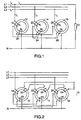
- Fig. 1 illustrates the balancer executed in accordance with the invention in association with an inductor connection.
- Fig. 2 illustrates the inductor connection effected in accordance with Fig. 1 supplemented by an additional open D-winding, to which external impedance elements can be connected.
- Fig. 3 illustrates in diagrammatic form the UI characteristic of a connection arrangement in accordance with Fig. 2.
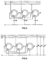
- Fig. 4 illustrates one of several transformer connections in accordance with the invention.
- Figs. 5 and 6 illustrate a connection arrangement partly with capacitors in a Y-connection, and partly connected as for a Z-inductor.
- Fig. 7 illustrates a graph in respect of the frequency for the zero-sequence impedance for a connection arrangement in accordance with the invention.
- the balancer illustrated in Fig. 1 is connected as an inductor at a desired point in a distribution circuit with three line phases, L1, L2 and L3.
- a load 10 is connected between line phase L1 and the neutral conductor N.
- the balancer in the present case is provided with three entirely separate magnetic cores, 12, 14 and 16, made of iron.
- the magnetic cores 12, 14, 16 are executed as separately awanged toroids, and each core is provided with two electrical windings 18,20; 22,24 and 26,28.
- the windings on the respective cores are totally isolated from one another in an electrical sense and can be arranged concentrically (not shown in the drawing), in which case they possess rather different impedances.
- the resistive dissimilarity at low frequencies is counteracted in the illustrated Z-connection by always connecting an external winding, for example 18, to an inner winding 24.
- the difference in inductance nevertheless remains.
- Both the resistive and the inductive part are balanced by the use of two-wire winding. Increased stray flux also means a resistive loss, amongst other things due to current displacement.
- the magnetic cores 12, 14, 16 are entirely separate, there is no magnetic connection between them. However, this separation means that the requirement for ampere-turn balance for each core 12, 14, 16 is very high.
- a construction with separate cores and extended windings meets the target of achieving the smallest possible leakage field.
- a Z-connected three-phase transformer/inductor which is executed in accordance with the principles of the invention, can also be used for voltage limitation.
- the inductor connection illustrated in Fig. 1 may thus be supplemented as shown in Fig. 2 with an additional D-winding 30, 32 and 34 on the respective cores 12, 14 and 16.
- the UI characteristic at the articulation point in accordance with the graph in Fig. 3 can be varied with the help of this.
- the curve on the left of the graph shows the conditions when the extra D-winding is connected, and the curve on the right shows the conditions without an extra D-winding.
- This can be utilised both for electrical distribution and for electrical power generation, for example in conjunction with the capacitor magnetisation of an asynchronous machine.
- the Z-connected inductor provides a circuit neutral point and load balancing, in addition to overvoltage protection.
- the balancer is used for voltage limitation of this kind, its frequency characteristics are determined by the design of the winding and the core.
- a Z-connected tripod transformer is normally wound with 15 per cent extra winding turns because of the phase position of the winding voltage. If three separate single-phase transformers are Z-connected in a toroid pattern to form a three-phase transformer, this can still be magnetised to full voltage without the need for additional winding turns. This is because the component voltages are deformed at the same time as the summated voltage over the windings is sinusoidal. This means that a transformer executed in accordance with the principles of the invention can be given a smaller number of winding turns, but with a certain increase in the harmonics content of the magnetisation current. This effect can be utilised partly to reduce the costs of a Z-transformer/inductor and partly for overvoltage limitation.
- the method of winding toroid transformers permits the use of core material that is not in sheet form or jointed form. Solid cores can also be used. Cores of ferrite, etc., which have very good high-frequency characteristics, can be used with advantage in interference filters.
- the primary winding of the three-phase transformer can be D-, Y- or Z-connected.
- the secondary side is always of Z-connected execution, however, so that it is symmetrical and of low impedance.
- the transformer connection illustrated in Fig. 4 by way of example has a D-connected primary side and a Z-connected secondary side.
- a customary limited short-circuit current will be obtained if the primary and secondary windings are executed separately.
- the advantages of this are that short-duration overvoltages can be dealt with on the primary side without the voltages on the secondary side being increased over the limitation level.
- One embodiment of a Z-connected three-phase transformer/inductor with separate toroid-shaped magnetic cores involves the three phases during no-load operation being totally symmetrical with regard to voltage, current, power and power factor.
- the power factor at the rated voltage is also significantly higher then when using a tripod core.
- a Z-inductor which consists of three single-phase reactors executed in accordance with the principles of invention, nevertheless exhibits a zero-sequence impedance which is significantly lower than its plus sequence impedance.
- the embodiment may be:
- the capacitors 38, 40, 42 occupy a large part of the fundamental tone voltage and thus reduce the size of the core.
- the zero-sequence impedance generally consists partly of the characteristics of the wound coil and partly of the inductive characteristics of the core (compare with the inductive part of the magnetisation circuit in a current transformer).
- the Z-connection provides a balancing of the flow between the windings. The better the connection between the windings, the less the core is used. A good connection is achieved if the windings are wound in two-wire configuration.
- the ability of the toroidal winding to provide a low leakage field has the effect of reducing partly the direct leakage inductance and partly the supplement from the core.
- the impedance at the fundamental tone frequency is almost only resistive, and the reactance changes slowly as the frequency increases. The rate of change depends on the manner of execution of the winding and the core. It can be seen from the graph that a minimum point is reached, which means that the zero-sequence impedance for third tones is lower than for the fundamental tone.
- the Z-connected toroidal transformer/reactor permits the zero-sequense impedance to be essentially resistive within a broad frequency range.
- the resistive part of the zero-sequence impedance then consists primarily of the resistance of the winding.
- the resistive frequency range can be further extended by the addition of the capacitors shown in Fig. 6.
- Intermediate voltages can occur in the event of phase interruption in a normal three-phase electrical distribution network, which includes asymmetrical loads - single-phase or two-phase.
- an increased voltage to earth occurs in any non-earthed phase conductors during the break-time.
- the extended earthing system can result in a voltage being applied between different earthed parts of the system, e.g. water pipe drains and water pipe protective earth connections, etc.
- balancing with the help of the balancer in accordance with the invention means that asymmetrical currents are fed back to the phases of the three-phase network as close as possible to the point of asymmetry.
- An embodiment of the balancer as a transformer or reactor means that the zero-sequence impedance is markedly resistive in nature, and that the external magnetic field is small as a result.
- a three-phase network which utilises the balancer in accordance with the invention, will perform more symmetrically under varying loads, disturbances, switching on and off and phase loss, etc. This means fewer disturbance problems in the form of vagabonding currents, magnetic fields, overvoltages and overloads in neutral conductors and conductor rails. Individual remedies to these problems were previously found, without regard to the system as a whole.
Landscapes
- Engineering & Computer Science (AREA)
- Power Engineering (AREA)
- Coils Of Transformers For General Uses (AREA)
- Filters And Equalizers (AREA)
- Coils Or Transformers For Communication (AREA)
- Transformers For Measuring Instruments (AREA)
- Regulation Of General Use Transformers (AREA)
- Supply And Distribution Of Alternating Current (AREA)
Applications Claiming Priority (3)
| Application Number | Priority Date | Filing Date | Title |
|---|---|---|---|
| SE9501600 | 1995-04-28 | ||
| SE9501600A SE9501600L (sv) | 1995-04-28 | 1995-04-28 | Symmetreringsdon med Z-kopplade lindningar |
| PCT/SE1996/000557 WO1996034443A1 (en) | 1995-04-28 | 1996-04-26 | Balancer executed with z-connected windings |
Publications (2)
| Publication Number | Publication Date |
|---|---|
| EP0885477A1 EP0885477A1 (en) | 1998-12-23 |
| EP0885477B1 true EP0885477B1 (en) | 2003-08-06 |
Family
ID=20398147
Family Applications (1)
| Application Number | Title | Priority Date | Filing Date |
|---|---|---|---|
| EP96913759A Expired - Lifetime EP0885477B1 (en) | 1995-04-28 | 1996-04-26 | Balancer executed with z-connected windings |
Country Status (10)
| Country | Link |
|---|---|
| EP (1) | EP0885477B1 (pl) |
| JP (1) | JPH11504198A (pl) |
| CN (1) | CN1185242A (pl) |
| AU (1) | AU710450B2 (pl) |
| CA (1) | CA2218851A1 (pl) |
| DE (1) | DE69629393D1 (pl) |
| NO (1) | NO310670B1 (pl) |
| PL (1) | PL180159B1 (pl) |
| SE (1) | SE9501600L (pl) |
| WO (1) | WO1996034443A1 (pl) |
Cited By (1)
| Publication number | Priority date | Publication date | Assignee | Title |
|---|---|---|---|---|
| RU2819297C1 (ru) * | 2023-05-03 | 2024-05-16 | Федеральное государственное бюджетное образовательное учреждение высшего образования "Иркутский государственный аграрный университет имени А.А. Ежевского" | Шунто-симметрирующее устройство для 3-х фазной электрической сети с нейтральным проводом |
Family Cites Families (5)
| Publication number | Priority date | Publication date | Assignee | Title |
|---|---|---|---|---|
| US2488628A (en) * | 1946-10-12 | 1949-11-22 | Henry L Hoeppner | Multiphase power transformer |
| JPS5114132B1 (pl) * | 1970-11-11 | 1976-05-07 | ||
| SU1023524A1 (ru) * | 1981-10-08 | 1983-06-15 | Вологодский Политехнический Институт | Устройство дл регулировани и симметрировани напр жений в трехфазной сети с нулевым проводом |
| SU1206881A1 (ru) * | 1983-09-23 | 1986-01-23 | Институт Электродинамики Ан Усср | Фильтросимметрирующее устройство дл трехфазных сетей с нулевым проводом |
| SU1504725A1 (ru) * | 1987-08-03 | 1989-08-30 | Институт Электродинамики Ан Усср | Трехфазна электрическа сеть |
-
1995
- 1995-04-28 SE SE9501600A patent/SE9501600L/xx not_active IP Right Cessation
-
1996
- 1996-04-26 WO PCT/SE1996/000557 patent/WO1996034443A1/en not_active Ceased
- 1996-04-26 CN CN96194040A patent/CN1185242A/zh active Pending
- 1996-04-26 DE DE69629393T patent/DE69629393D1/de not_active Expired - Lifetime
- 1996-04-26 AU AU56612/96A patent/AU710450B2/en not_active Ceased
- 1996-04-26 PL PL96322981A patent/PL180159B1/pl not_active IP Right Cessation
- 1996-04-26 EP EP96913759A patent/EP0885477B1/en not_active Expired - Lifetime
- 1996-04-26 CA CA002218851A patent/CA2218851A1/en not_active Abandoned
- 1996-04-26 JP JP8532446A patent/JPH11504198A/ja active Pending
-
1997
- 1997-10-27 NO NO19974963A patent/NO310670B1/no not_active IP Right Cessation
Cited By (1)
| Publication number | Priority date | Publication date | Assignee | Title |
|---|---|---|---|---|
| RU2819297C1 (ru) * | 2023-05-03 | 2024-05-16 | Федеральное государственное бюджетное образовательное учреждение высшего образования "Иркутский государственный аграрный университет имени А.А. Ежевского" | Шунто-симметрирующее устройство для 3-х фазной электрической сети с нейтральным проводом |
Also Published As
| Publication number | Publication date |
|---|---|
| AU710450B2 (en) | 1999-09-23 |
| SE503518C2 (sv) | 1996-07-01 |
| DE69629393D1 (de) | 2003-09-11 |
| AU5661296A (en) | 1996-11-18 |
| CN1185242A (zh) | 1998-06-17 |
| NO974963L (no) | 1997-12-23 |
| PL180159B1 (pl) | 2000-12-29 |
| CA2218851A1 (en) | 1996-10-31 |
| PL322981A1 (en) | 1998-03-02 |
| JPH11504198A (ja) | 1999-04-06 |
| NO974963D0 (no) | 1997-10-27 |
| SE9501600L (sv) | 1996-07-01 |
| SE9501600D0 (sv) | 1995-04-28 |
| NO310670B1 (no) | 2001-08-06 |
| WO1996034443A1 (en) | 1996-10-31 |
| EP0885477A1 (en) | 1998-12-23 |
Similar Documents
| Publication | Publication Date | Title |
|---|---|---|
| EP0684679B1 (en) | Method for reducing waveform distortion in an electrical utility system and circuit for an electrical utility system | |
| US4473817A (en) | Coupling power line communications signals around distribution transformers | |
| US4677401A (en) | Noise filter for three-phase four-wire system | |
| US4458236A (en) | Communications signal coupling around wye/delta power transformation | |
| JP5060244B2 (ja) | リアクトル | |
| US5206539A (en) | Transformer with cancellation of harmonic currents by phase shited secondary windings | |
| EP1456728B1 (en) | Device with controllable impedance | |
| CN109637791A (zh) | 一种逆斯科特变压器 | |
| EP0885477B1 (en) | Balancer executed with z-connected windings | |
| AU5411696A (en) | Circuitry for reduction of the magnetic field in the vicinity of multiphase power lines | |
| JPH07254520A (ja) | 三相負荷時電圧位相調整変圧器 | |
| EA025827B1 (ru) | Трехфазный симметрирующий автотрансформатор (его варианты) | |
| EP0216500B1 (en) | Electromagnetic induction apparatus | |
| CN216054241U (zh) | 一种新型电流互感器 | |
| RU2217830C2 (ru) | Электрический реактор с подмагничиванием | |
| US2357098A (en) | Transformer | |
| JPS5821309A (ja) | 負荷時タツプ切換変圧器 | |
| RU2809838C1 (ru) | Трехфазное фильтрокомпенсирующее устройство | |
| JPS6184008A (ja) | 3相変圧器 | |
| JPH05159952A (ja) | 零相変流器およびその巻線方法 | |
| CN1167178C (zh) | 静止无功补偿装置 | |
| US2667617A (en) | Polyphase transformer system with grounded neutral | |
| KR0141448B1 (ko) | 상호유도리액터 구성방법 | |
| CN2387654Y (zh) | 静止无功补偿装置 | |
| US1475968A (en) | Best available |
Legal Events
| Date | Code | Title | Description |
|---|---|---|---|
| PUAI | Public reference made under article 153(3) epc to a published international application that has entered the european phase |
Free format text: ORIGINAL CODE: 0009012 |
|
| 17P | Request for examination filed |
Effective date: 19971128 |
|
| AK | Designated contracting states |
Kind code of ref document: A1 Designated state(s): BE DE DK ES FI FR GB GR IT NL PT |
|
| 17Q | First examination report despatched |
Effective date: 20001009 |
|
| GRAH | Despatch of communication of intention to grant a patent |
Free format text: ORIGINAL CODE: EPIDOS IGRA |
|
| GRAH | Despatch of communication of intention to grant a patent |
Free format text: ORIGINAL CODE: EPIDOS IGRA |
|
| GRAA | (expected) grant |
Free format text: ORIGINAL CODE: 0009210 |
|
| AK | Designated contracting states |
Designated state(s): BE DE DK ES FI FR GB GR IT NL PT |
|
| PG25 | Lapsed in a contracting state [announced via postgrant information from national office to epo] |
Ref country code: NL Free format text: LAPSE BECAUSE OF FAILURE TO SUBMIT A TRANSLATION OF THE DESCRIPTION OR TO PAY THE FEE WITHIN THE PRESCRIBED TIME-LIMIT Effective date: 20030806 Ref country code: IT Free format text: LAPSE BECAUSE OF FAILURE TO SUBMIT A TRANSLATION OF THE DESCRIPTION OR TO PAY THE FEE WITHIN THE PRESCRIBED TIME-LIMIT;WARNING: LAPSES OF ITALIAN PATENTS WITH EFFECTIVE DATE BEFORE 2007 MAY HAVE OCCURRED AT ANY TIME BEFORE 2007. THE CORRECT EFFECTIVE DATE MAY BE DIFFERENT FROM THE ONE RECORDED. Effective date: 20030806 Ref country code: FR Free format text: LAPSE BECAUSE OF FAILURE TO SUBMIT A TRANSLATION OF THE DESCRIPTION OR TO PAY THE FEE WITHIN THE PRESCRIBED TIME-LIMIT Effective date: 20030806 Ref country code: FI Free format text: LAPSE BECAUSE OF FAILURE TO SUBMIT A TRANSLATION OF THE DESCRIPTION OR TO PAY THE FEE WITHIN THE PRESCRIBED TIME-LIMIT Effective date: 20030806 Ref country code: BE Free format text: LAPSE BECAUSE OF FAILURE TO SUBMIT A TRANSLATION OF THE DESCRIPTION OR TO PAY THE FEE WITHIN THE PRESCRIBED TIME-LIMIT Effective date: 20030806 |
|
| REG | Reference to a national code |
Ref country code: GB Ref legal event code: FG4D |
|
| REF | Corresponds to: |
Ref document number: 69629393 Country of ref document: DE Date of ref document: 20030911 Kind code of ref document: P |
|
| PG25 | Lapsed in a contracting state [announced via postgrant information from national office to epo] |
Ref country code: GR Free format text: LAPSE BECAUSE OF FAILURE TO SUBMIT A TRANSLATION OF THE DESCRIPTION OR TO PAY THE FEE WITHIN THE PRESCRIBED TIME-LIMIT Effective date: 20031106 Ref country code: DK Free format text: LAPSE BECAUSE OF FAILURE TO SUBMIT A TRANSLATION OF THE DESCRIPTION OR TO PAY THE FEE WITHIN THE PRESCRIBED TIME-LIMIT Effective date: 20031106 |
|
| PG25 | Lapsed in a contracting state [announced via postgrant information from national office to epo] |
Ref country code: DE Free format text: LAPSE BECAUSE OF FAILURE TO SUBMIT A TRANSLATION OF THE DESCRIPTION OR TO PAY THE FEE WITHIN THE PRESCRIBED TIME-LIMIT Effective date: 20031107 |
|
| PG25 | Lapsed in a contracting state [announced via postgrant information from national office to epo] |
Ref country code: ES Free format text: LAPSE BECAUSE OF FAILURE TO SUBMIT A TRANSLATION OF THE DESCRIPTION OR TO PAY THE FEE WITHIN THE PRESCRIBED TIME-LIMIT Effective date: 20031117 |
|
| NLV1 | Nl: lapsed or annulled due to failure to fulfill the requirements of art. 29p and 29m of the patents act | ||
| PG25 | Lapsed in a contracting state [announced via postgrant information from national office to epo] |
Ref country code: PT Free format text: LAPSE BECAUSE OF FAILURE TO SUBMIT A TRANSLATION OF THE DESCRIPTION OR TO PAY THE FEE WITHIN THE PRESCRIBED TIME-LIMIT Effective date: 20040106 |
|
| PG25 | Lapsed in a contracting state [announced via postgrant information from national office to epo] |
Ref country code: GB Free format text: LAPSE BECAUSE OF NON-PAYMENT OF DUE FEES Effective date: 20040426 |
|
| PLBE | No opposition filed within time limit |
Free format text: ORIGINAL CODE: 0009261 |
|
| STAA | Information on the status of an ep patent application or granted ep patent |
Free format text: STATUS: NO OPPOSITION FILED WITHIN TIME LIMIT |
|
| 26N | No opposition filed |
Effective date: 20040507 |
|
| EN | Fr: translation not filed | ||
| GBPC | Gb: european patent ceased through non-payment of renewal fee |
Effective date: 20040426 |