EP0884873A2 - Relaisnetz für Internet-Protokoll - Google Patents
Relaisnetz für Internet-Protokoll Download PDFInfo
- Publication number
- EP0884873A2 EP0884873A2 EP98108622A EP98108622A EP0884873A2 EP 0884873 A2 EP0884873 A2 EP 0884873A2 EP 98108622 A EP98108622 A EP 98108622A EP 98108622 A EP98108622 A EP 98108622A EP 0884873 A2 EP0884873 A2 EP 0884873A2
- Authority
- EP
- European Patent Office
- Prior art keywords
- router
- packet
- destination
- network
- egress
- Prior art date
- Legal status (The legal status is an assumption and is not a legal conclusion. Google has not performed a legal analysis and makes no representation as to the accuracy of the status listed.)
- Withdrawn
Links
Images

Classifications
-
- H—ELECTRICITY
- H04—ELECTRIC COMMUNICATION TECHNIQUE
- H04L—TRANSMISSION OF DIGITAL INFORMATION, e.g. TELEGRAPHIC COMMUNICATION
- H04L45/00—Routing or path finding of packets in data switching networks
-
- H—ELECTRICITY
- H04—ELECTRIC COMMUNICATION TECHNIQUE
- H04L—TRANSMISSION OF DIGITAL INFORMATION, e.g. TELEGRAPHIC COMMUNICATION
- H04L12/00—Data switching networks
- H04L12/28—Data switching networks characterised by path configuration, e.g. LAN [Local Area Networks] or WAN [Wide Area Networks]
- H04L12/46—Interconnection of networks
- H04L12/4604—LAN interconnection over a backbone network, e.g. Internet, Frame Relay
- H04L12/4608—LAN interconnection over ATM networks
-
- H—ELECTRICITY
- H04—ELECTRIC COMMUNICATION TECHNIQUE
- H04L—TRANSMISSION OF DIGITAL INFORMATION, e.g. TELEGRAPHIC COMMUNICATION
- H04L67/00—Network arrangements or protocols for supporting network services or applications
- H04L67/50—Network services
- H04L67/56—Provisioning of proxy services
- H04L67/563—Data redirection of data network streams
-
- H—ELECTRICITY
- H04—ELECTRIC COMMUNICATION TECHNIQUE
- H04L—TRANSMISSION OF DIGITAL INFORMATION, e.g. TELEGRAPHIC COMMUNICATION
- H04L69/00—Network arrangements, protocols or services independent of the application payload and not provided for in the other groups of this subclass
- H04L69/22—Parsing or analysis of headers
-
- H—ELECTRICITY
- H04—ELECTRIC COMMUNICATION TECHNIQUE
- H04L—TRANSMISSION OF DIGITAL INFORMATION, e.g. TELEGRAPHIC COMMUNICATION
- H04L9/00—Cryptographic mechanisms or cryptographic arrangements for secret or secure communications; Network security protocols
- H04L9/40—Network security protocols
-
- H—ELECTRICITY
- H04—ELECTRIC COMMUNICATION TECHNIQUE
- H04Q—SELECTING
- H04Q11/00—Selecting arrangements for multiplex systems
- H04Q11/04—Selecting arrangements for multiplex systems for time-division multiplexing
- H04Q11/0428—Integrated services digital network, i.e. systems for transmission of different types of digitised signals, e.g. speech, data, telecentral, television signals
- H04Q11/0478—Provisions for broadband connections
-
- H—ELECTRICITY
- H04—ELECTRIC COMMUNICATION TECHNIQUE
- H04L—TRANSMISSION OF DIGITAL INFORMATION, e.g. TELEGRAPHIC COMMUNICATION
- H04L12/00—Data switching networks
- H04L12/54—Store-and-forward switching systems
- H04L12/56—Packet switching systems
- H04L12/5601—Transfer mode dependent, e.g. ATM
- H04L2012/5638—Services, e.g. multimedia, GOS, QOS
- H04L2012/5665—Interaction of ATM with other protocols
- H04L2012/5667—IP over ATM
-
- H—ELECTRICITY
- H04—ELECTRIC COMMUNICATION TECHNIQUE
- H04L—TRANSMISSION OF DIGITAL INFORMATION, e.g. TELEGRAPHIC COMMUNICATION
- H04L12/00—Data switching networks
- H04L12/54—Store-and-forward switching systems
- H04L12/56—Packet switching systems
- H04L12/5601—Transfer mode dependent, e.g. ATM
- H04L2012/5638—Services, e.g. multimedia, GOS, QOS
- H04L2012/5665—Interaction of ATM with other protocols
- H04L2012/5668—Next hop resolution protocol [NHRP]
Definitions
- the present invention relates generally to communication systems and more particularly to an internetwork protocol relay network that allows for the transmission of Internet protocol traffic faster and/or more efficiently than existing schemes.
- IP Internet Protocol
- datagrams or packets are sent from a source to a destination.
- IP backbone which is a high-speed, high performance network that links other networks together.
- the source and destination of a datagram can be, for example, the personal computers of two different users.
- a datagram traverses many different routers on its transmission path from a source to its intended destination.
- a router is simply a host computer that forwards network traffic from one connected network to another regardless of whether or not the source and destination networks are of the same type.
- a router When a router receives a datagram, it reads the address of the destination host to determine to which router the datagram should be forwarded. It then replaces the address of the present router with the address of the next router in the datagram ' s address header before forwarding the datagram along its transmission path.
- Layer 3 processing refers to the network layer of either the Open Systems Interconnection (OSI) seven-layer model or to the Transmission Control Protocol/Internet Protocol (TCP/IP) model.
- OSI Open Systems Interconnection
- TCP/IP Transmission Control Protocol/Internet Protocol
- IP datagrams across the Internet traverses many routers until it reaches its destination, each of these routers performing Layer-3 processing on the datagram.
- This processing scheme is generally referred to as the Classical IP " system or model.
- a disadvantage associated with this system is that the hop-by-hop transmission process and the associated Layer-3 processing at each router contributes to significant and unpredictable delays in the transmission of IP packets across a network.
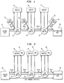
- FIG. 1 illustrates a schematic view of this type of network.
- source host 10 wishes to send a packet to destination host 20 which is outside the local IP subnet (LIS " ) of the source host 10.
- the source host 10 sends the packet to router 11 across ATM switch 12 designated in Fig. 1 as path-1.
- Establishment of path-1 over the ATM network is accomplished by source host 10 translating the IP address of router 11 to an ATM address in order to build a virtual path to router 11.
- the Classical IP Over ATM model provides ARP (Address Resolution Protocol) server 13 which performs an IP to ATM address translation for all registered hosts and routers within a logical IP Subnet (LIS).
- ARP Address Resolution Protocol
- source 10 sends an address resolution request to ARP server 13 for the ATM address corresponding to the IP address of router 11 in the same LIS.
- ARP server 13 sends an address resolution response with information associated with the ATM address corresponding to router 11.
- source 10 builds path-1 across the ATM network to the ATM address of router 11.
- router 11 makes a determination that the next hop for transmission of the packet is router 14 and forwards the packet to router 14, across ATM switches 12 and 15, designated as path-2, discovering router 14's ATM address using ARP server 16.
- router 14 forwards the packet through ATM switches 15 and 17, designated as path-3 in Fig. 1, to router 17 using ARP server 19.
- Router 17 in turn makes a determination that it is the last hop router on the path to destination 20.
- Router 17 sends the packet to destination 20 across ATM switch 18 designated as path-4 in Fig. 1 using ARP server 21.
- this type of network maintains traditional IP switching on top of an ATM network, it views the underlying ATM network as just another OSI Layer-2 technology, and thus does not fully capitalize on the benefits of ATM.
- the IP routers 11, 14, and 17 and the ATM switches 12, 15, and 18 run separate protocols to determine the address of the next hop making this type of network configuration less efficient.
- each router along the packet ' s transmission path determines the next hop router toward its destination. This requires each router to perform Layer-3 processing on the packet to inspect the destination IP address and derive the next hop router from routing tables determined by a routing protocol and stored in each router.
- this system also includes IP to ATM address mapping steps, one in each ARP server, and four ATM switched virtual path (SVC) establishment steps along the path between the source host 10 and destination host 20, thereby adding more processing steps to the routing scheme.
- SVC ATM switched virtual path
- a number of additional network protocol software schemes have attempted to speed-up and increase the efficiency of Internet transmissions. These systems can generally be classified into two groups; the systems in the first group attempt to reduce the amount of Layer-3 processing at intermediate routers; and the systems in the second group attempt to reduce or eliminate the number of router hops in a datagram ' s path.
- the systems in the first group attempt to reduce the amount of Layer-3 processing at intermediate routers; and the systems in the second group attempt to reduce or eliminate the number of router hops in a datagram ' s path.
- a network processing scheme known as the Classical IP Model-Cut Through Routing " , attempts to completely eliminate router hops, however this system is only available in situations where there is a large IP data flow from one particular end point to another.
- This type of processing system is schematically shown in Fig. 2.
- source host 30 determines the ATM address corresponding to the IP address of destination host 40 and establishes a cut-through path, or a virtual circuit from the source host 30 to the destination host 40 thereby avoiding routers 41, 42 and 43.
- the cut-through path for a datagram is defined from source host 30 through ATM switch 31 through ATM switch 32 through ATM switch 33 to destination host 40.
- NHRP Next Hop Routing Protocol
- source host 30 connected to ATM switch 31 becomes an NHRP client when it registers its IP-ATM address with its specified NHS 34, similar to the ARP server in the classical Hop-by-Hop network.
- NHS 34 can be stored in Router 41 or in ATM switch 31.
- an NHRP client such as source host 30 desires to switch its data traffic from the default (hop-by-hop) routed path to a cut-through path, it must first acquire the address of destination host 40 by way of a request/response process. This process begins by source host 30 sending an NHRP request to NHS 34 stored in router 41 via path-1a to obtain the mapping of the IP address of destination 40 to its corresponding ATM address.
- NHS 34 receives the request and either has the address mapping in its database because destination 40 is in the same LIS, or because it learned the address mapping from a previous address resolution request/response process and cached the address of destination host 40. However, if NHS 34 does not have the address of destination 40, it must forward the NHRP request to NHS 35 stored in router 42 via path-2a. This process continues to NHS 36 stored in router 43 via path-3a which is the last NHS on the transmission path to the destination 40 via path-4a. The NHRP response which carries the ATM address of destination 40 follows the reverse path back to source 30 and gets forwarded to source host 30 by NHS 34. Thereafter, source host 30 builds a virtual path to the destination without going through routers 41, 42 and 43 along the transmission path between source 30 and destination 40. Thus, to establish the address mapping for a cut-through path between source 30 and destination 40, a request/response process using Layer-3 processing at each router, substantially similar to the hop-by-hop process, must be performed at least once.
- IP Navigator combines Wide Area Network (WAN) switching and IP routing to store the end destination switch, the switch which communicates with an egress router, for each IP packet sent over the network. In this manner, switches within the network function as IP routers. Once the end destination switch is determined, the IP packet is forwarded through a pre-established multipoint-to-point tunnel " to that switch. Multipoint-to-point tunneling is a method by which once a virtual circuit or cut-through is established, the address information is broadcast to all other nodes in the network. Once at the end destination switch, a routing table lookup is performed to determine the proper egress port of the end switch to forward the IP packet. Similar to the cut-through routing scheme, this software model has applicability only to ATM networks and suffers from the Virtual Circuit Explosion problem.
- WAN Wide Area Network
- Tag-switching and IP-switching are examples of two network schemes that attempt to reduce the amount of Layer-3 processing at intermediate routers. However, each of these network systems do not reduce the number of router hops in the path of an IP datagram.
- Tag-switching is an IETF proposal that inserts a so called "tag" or a shim layer between the Layer-2 (Data Link Layer) and the Layer-3 (Network Layer) of the OSI model. If the data link layer is ATM, tag switching proposes to use some portion of the Virtual Path Identifier (VPI) and Virtual Circuit Identifier (VCI) of the 53 byte ATM cell header as the tag.
- VPN Virtual Path Identifier
- VCI Virtual Circuit Identifier
- Each IP router between the source and destination inspects the inserted tag and makes a determination, based on local look-up tables, which port to forward the IP datagram.
- Each router establishes a table entry in its database indicating that for a particular tag, the datagram originates from a first router and should be forwarded onto a particular port to a second router.
- the first router performs a call setup function where the first router informs the second router on the path, by a "tag distribution protocol," that the incoming IP traffic to be forwarded to the second router has a particular tag identifier.
- each router inspects the tag, determining which downstream router to forward the datagram to, replacing the existing tag with another tag that denotes the address of the next downstream router, and forwarding the datagram accordingly until it reaches its destination.
- each router inspects the VPI/VCI value at the packet ' s header to make a forwarding decision.
- the tag switching involves swapping VPI/VCI values between incoming and outgoing ports of each router on an IP packet ' s transmission path.
- IP-switching used only in ATM networks, also attempts to limit the amount of Layer-3 processing performed on an IP packet during transmission.
- the general concept of IP-switching is similar to Tag- switching, however IP-switching does not use the ATM signaling and call set-up process used in Tag-switching.
- the ATM switches are used simply to relay the IP datagrams in 53 octet chunks with a short tag attached to each packet which includes various VPI/VCI values, the use of which are determined locally by each router. Both Tag and IP-switching schemes reduce the amount of processing on each IP datagram by manipulating the tags, however the number of router hops is not reduced.
- each intermediate hop is a router
- the router does not make the appropriate layer-3 header modifications such as incrementing the hop count and changing the originator's IP address.
- the tag swapping still requires each router to parse the header of the IP packet to identify the tag and to write on the packet header to swap the tag.
- None of the above described systems both reduces the number of router hops an IP packet experiences as it traverses a network while also reducing the amount of Layer-3 processing in each hop. As many more routers and Web servers are being deployed, a high-speed Internet backbone is needed more than ever to allow network growth and to improve data transmission performance.
- the present invention meets the needs and avoids the disadvantages and drawbacks of the above described network schemes and processes by providing an internetwork relay system and method for transmitting IP traffic that reduces the number of router hops an IP packet makes during transmission over the network and also reduces the amount of Layer-3 processing performed on each IP packet as it traverses the network.
- a relay network includes an ingress router which communicates with and receives an IP packet from a source network.
- the ingress router attaches a globally unique label to each IP packet. The label is used to forward the IP packet across the network.
- a relay switch network communicates with and receives the IP packet from the ingress router based on information included in the label.
- the switch network forwards the IP packet along its transmission path based on destination information included in its attached label.
- An egress router receives the IP packet from the switch network and forwards it to a destination network. Once received, the destination network forwards the IP packet to its intended destination.
- a relay network in another embodiment, includes an ingress router which communicates with and receives an Internet protocol datagram form a source network.
- the ingress router attaches to the datagram a label that includes information corresponding to the datagram ' s intended destination.
- the datagram is forwarded to a switch network from the ingress router.
- the switch forwards the datagram to an egress router such that the egress router is one router hop away from the ingress router.
- Fig. 1 is a block diagram of a classical IP over ATM network.
- Fig. 2 is a block diagram of an IP network with cut through routing.
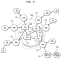
- Fig. 3 is a schematic view of a Relay Network in accordance with the present invention in which a plurality of routers define the edge of the Network and a plurality of switches define the Network ' s core.
- Fig. 4 illustrates the processing flow of an IP datagram as it traverses the Relay Network shown in Fig. 3.
- FIG. 3 the principles of the present invention are illustrated in this simplified functional view of an IP Relay Network interconnecting Local Area Networks (LAN " ) or IP Networks 100 - 105, IP Relay Routers ( IPRR “ ) 110 - 115 and IP Relay Switches ( IPRS “ ) 120 - 123.
- IPRR ' s 110 - 115 form the edge " of the network and IPRS ' s 120 - 123 form the core " of the network providing connectivity among the IPRR ' s.
- LAN ' s 100 - 105 represent groups of users typically located within close proximity to one another and connected together to form a network.
- Fig. 3 illustrates a particular configuration of the present IP Relay Network having a distinct number of routers, switches and IP Networks/LANs, it is understood that the size of the network is not limited by the number of components nor by the interconnection between these components.
- LAN ' s 100 - 105 communicate with IPRR ' s 110 - 115, respectively. However, a particular LAN may also communicate with one or more IPRR ' s depending on the network configuration.
- Each IPRR 110 - 115 is a multihomed host that receives IP packets addressed to itself or if an IP packet is addressed to another host, each IPRR forwards the packet to another router via one or more IPRS ' s 120 - 123 within the relay network.
- Each IPRR 110 - 115 performs Layer-3 processing on each IP packet received. Layer-3 processing generally refers to the parsing-out and reading of the IP address included in the header portion of each IP packet. The information contained in this address header includes the source IP address and the destination IP address.
- Each IPRR 110 -115 examines the destination address and compares it to its own network IP address. If the destination and source addresses are on the same LAN, then the IP packet is routed directly to the host with that destination address. If the destination address is not attached to the same LAN, one of the IPRR ' s 110 - 115 which communicates with the LAN forwards the IP packet to a particular IPRS 120 - 123 based on information contained in a routing table the details of which will be described in more detail below.
- IPRR IP Resource Identifier
- IPRR IP Resource Identifier
- Layer-3 network layer
- This label will be read by one or more IPRS ' s 120 - 125 as the IP packet is forwarded over the network toward its destination.
- the IPRS may forward the IP packet to another IPRS on the transmission path or to an egress router depending on the packet ' s intended destination.
- An IPRR can be physically connected to more than one IPRS. In this case the last IPRS in the transmission path of an IP packet is the one that lies on the optimal path to the egress IPRR as determined by the routing algorithm.
- the label attached to each IP packet by an ingress IPRR has significance in that certain portions of the label identify certain components or groups of components of the Relay Network. This concept is similar to a telephone number in that a three digit area code designates in what part of the country a phone is located, the three digit exchange indicates a region within the area code, and the last four numbers specify a particular line within the exchange.
- the label in the present Relay Network possesses information corresponding to where within the Network a destination is located. For example, the first part of the label may indicate which IPRS or group of IPRS ' s within the network the IP packet is intended. Another portion of the label may indicate which port on the IPRS the packet should be sent to, or in other words, which egress IPRR.
- Each IPRS is a data link or Layer-2 device in that it reads the label attached to each IP packet and determines the next stop, either another IPRS or an egress router, for the IP packet along its transmission path. Once the IP packet is received by an egress router, the label is removed and the IP packet is forwarded to its destination. Unlike Tag and IP-switching schemes, an IPRS in accordance with the present invention does not modify or swap the label attached to an IP packet as the packet is forwarded along its transmission path. Accordingly, the forwarding operation of the IPRS ' s is amenable to high speed hardware implementations thereby achieving large forwarding rates and through-puts required by Internet and Intranet applications.
- a source host 90 such as a personal computer, connected to LAN 100 sends an IP packet to destination host 95, also a personal computer, connected to LAN 103.
- the IP packet is transmitted from host 90 through LAN 100 to IPRR 110 in a conventional manner.
- IPRR 110 considered the ingress IPRR, reads the address header in the IP packet and determines that the destination host is not attached to a LAN to which IPRR 110 can deliver the packet directly.
- IPRR 110 performs Layer-3 processing on the IP packet, as well as attaching a label to the IP packet based on information included in a routing table stored in a memory device in IPRR 110 indicating that the next hop router is IPRR 113, considered the egress IPRR. In this manner, ingress IPRR 110 views egress IPRR 113 as being only one hop away.
- IPRS 120 which may be, for example, an ATM switch. This forwarding process is performed by mapping the address information stored in IPRR 110's routing table with address information stored in a forwarding table also stored in IPRR 110.
- IPRS 120 reads the label and forwards the IP packet to IPRS 122 based on information stored in a forwarding table at IPRS 120 corresponding to egress IPRR 113.
- IPRS 122 also reads the label and forwards the IP packet to egress IPRR 113 based on information stored in its forwarding table corresponding to egress IPRR 113.
- Egress IPRR 113 receives the IP packet, performs Layer-3 processing to reassemble the packet, and forwards it through LAN 103 to destination host 95.
- the IP Relay Network in accordance with the present invention can accommodate several different label formats attached to an IP packet by an ingress IPRR.
- identification information corresponding to the egress IPRR IPRR ID
- the label may include identification information corresponding to the last IPRS (IPRS ID) that communicates with the egress IPRR and the IPRS port (PORT ID) on which the egress IPRR communicates.
- IPRS ID the last IPRS
- PORT ID the IPRS port
- a FLOW ID may also be included in the label to differentiate between multiple IP packets bound for the same destination. This allows IPRSs along the IP packet ' s transmission path to provide different quality of service treatment to different IP packets.
- the FLOW ID can denote that a confirmation message indicating that the packet has been received needs to be sent back to the source.
- the FLOW ID may be used for routing IP packet traffic across multiple least-cost paths in the relay network.
- IPRRs 110 - 115 learn about what labels to attach to an IP packet for a given egress IPRR is based on extensions to standard IP routing protocols such as OSPF (Open Shortest Path First).
- IPRRs 110 - 115 and IPRSs 120 - 123 participate in a common routing and topology exchange protocol which not only distributes the usual IP routing and link state topology information, but also distributes the IPRS ID and PORT ID or alternatively the IPRR ID information for the entire network depending on which label version is employed. This protocol allows each IPRR 110 - 115 to construct its routing and forwarding tables which are stored in a memory device, or in different memory devices within each IPRR.
- each IPRR 110 - 115 For a given destination IP address, the routing table stored in each IPRR 110 - 115 provides the label to be attached to the IP datagram.
- the routing table contains identification information corresponding to an egress IPRR for addressing each IP packet as opposed to only the next hop router address used in other network systems.
- the routing table stored in each IPRR 110 - 115 has the general structure illustrated in Table 1.
- DESTINATION IP ADDRESS FLOW ID LAST IPRR ID LAST ⁇ IPRS ID, PORT ID ⁇ Referring to Table 1, the Destination IP Address is obtained from reading the header address portion of an IP packet.
- the FLOW ID as described above, is assigned locally by the ingress IPRR based on policies defined by the network administrator.
- the LAST IPRR ID identifies the egress IPRR to which the destination host communicates via a LAN.
- the LAST ⁇ IPRS ID, PORT ID ⁇ is an optional field where the LAST IPRS ID refers to the IPRS that communicates with the egress IPRR and the PORT ID refers to the physical port that the egress IPRR is connected to via the last IPRS.
- the routing table stored in each IPRR maps the destination address of a particular IP packet to either the egress IPRR (LAST IPRR ID) or to the IPRS and physical port that communicates with the egress IPRR (LAST IPRS ID, PORT ID).
- each IPRR has a complete knowledge of the routed network. As additional IPRRs are added to the relay network, the routing tables in each IPRR are dynamically updated through the use of a routing algorithm.
- the routing table stored within each IPRR contains the egress IPRR to en route to each Layer 3 destination as opposed to the next hop router.
- a default IPRR can also be implemented in the Relay Network in accordance with the present invention by designating one of the IPRRs 110 - 115 as the default IPRR. If the IP Relay Network is connected to a non-IP network, then the default IPRR will be considered the egress IPRR for traffic destined for such non-IP networks. The default IPRR performs the necessary Layer 3 processing on the IP traffic and forwards it to the first router of the non-IP Relay Network. For example, if a packet is sent from IP network 105 to non-IP network 155, IPRR 115 is considered the default IPRR and performs the necessary Layer 3 processing on the packet. The packet is then forwarded to non-IP Router 150 which in turn forwards it to its destination in non-IP network 155.
- the forwarding table stored in each IPRR 110 - 115 has the general structure shown in Table 2.
- EGRESS IPRR ID LAST IPRS ID PORT ID(1) PORT ID(2) referring to Table 2, the EGRESS IPRR ID identifies the egress IPRR to which the IP packet is forwarded.
- the LAST IPRS ID refers to the IPRS that is physically connected to the egress IPRR.
- the PORT ID fields have local significance depending on the particular IPRR and the destination of the IP Packet.
- the PORT ID(1) and PORT ID(2)fields refer to the port from the ingress IPRR onto which the IP packet is sent. In other words, the PORT ID (1) and PORT ID (2) fields indicate which IPRS the IP packet is forwarded to from the ingress IPRR.
- IPRR 110 Two different PORT ID ' s, namely PORT ID(1) and PORT ID(2) can be used since there may be several alternate (least-cost) paths to an IP packet ' s destination.
- the forwarding table in IPRR 110 may have a PORT ID(1) corresponding to IPRS 120 and a PORT ID(2) corresponding to IPRS 121. If the egress IPRR is IPRR 112, then ingress IPRR 110 can forward the packet to either IPRS 120 or IPRS 121 depending on the IP traffic currently being sent over the network which impacts the least-cost path to egress IPRR 112 for that particular IP packet.
- the IPRR may choose among these alternate ports available to route the IP packet to the egress IPRR based on its local algorithm.
- Each IPRS 120 - 123 stores a forwarding table in memory, each of which has substantially the same structure as that shown in Table 2 above.
- the PORT ID refers to the port on which the ingress IPRR should en route the IP datagram to the egress IPRR via the IPRS communicating with the egress IPRR. Similar to the different paths available to an ingress IPRR, PORT ID(1) and PORT ID(2) indicate alternative, least-cost paths to the next IPRS in an IP packet ' s transmission path.
- the IPRS When an IPRS receives an IP packet, the IPRS reads the IPRS ID portion of the label and maps it to the LAST IPRS ID entry in its forwarding table to determine the outgoing PORT ID of the IPRS which is connected to either the next IPRS along the transmission path or to an egress IPRR depending on the packet ' s destination. Accordingly, the PORT ID field has local significance in that it denotes the port of an IPRS on which an IP packet is routed to the next IPRS or to an egress IPRR. Moreover, if PORT ID(2) is selected and load balancing is enabled, then the FLOW ID field is hashed to select the particular outgoing port on an IPRS.
- the FLOW ID field may also be used, for example, to differentiate between IP traffic requiring a secure path across the network denoted as FLOW ID(1) and a packet having a less secure path across the network denoted as FLOW ID(2).
- FLOW ID(1) a secure path across the network
- FLOW ID(2) a packet having a less secure path across the network denoted as FLOW ID(2).
- the forwarding table in each IPRS and IPRR are also dynamically updated based on the topology or link-state of the network.
- the optimal paths across the core network may change and the forwarding tables change accordingly.
- FIG. 5 illustrates the software processing flow of an IP datagram as it traverses an IP Relay Network in accordance with the present invention.
- the process begins in step 200 when one of the IPRRs 110 - 115, considered the ingress IPRR, receives an IP datagram from one of the end stations connected to a LAN or IP network 100 - 105.
- the ingress IPRR parses the IP datagram and reads the IP address of the destination connected to a particular LAN 100 -105. The IP address is contained in the header portion of the IP datagram.
- the ingress IPRR checks to determine if there is a routing table entry corresponding to the destination IP address for the IP packet received.
- step 207 is performed and the ingress IPRR retrieves the routing table entry to determine the "label" to be attached to the IP packet.
- the egress IPRR uses the table entry corresponding to the default router as the egress IPRR as shown in step 209 and the process proceeds to step 207 described above.
- IPRR-100 attaches the label to the IP datagram using Layer-3 processing.
- IPRR-100 checks to determine if there is a forwarding table entry in its database for the LAST IPRR ID.
- test result If the test result is YES, it checks to determine if it is the last hop to the destination station in conditional branch point 271. If the test result is YES, then the IPRR removes the label and forwards the IP datagram to its final destination in step 291. The process exists in step 250.
- step 271 If the test in step 271 is NO, indicating that the receiving entity is not the last IPRR, then it sends the IP datagram to its port identified by the PORT ID retrieved from the forwarding table in step 221. If the test result in step 211 is NO, indicating that there is no forwarding table entry for the egress IPRR, then the process exists in step 250.
- an IPRS 120 - 123 which receives the packet from the ingress IPRR determines if any forwarding entry exists in the forwarding table stored in its memory. If a forwarding table entry does exist then the IP datagram is forwarded to the next IPRS on its way to the egress IPRR. The process returns to step 211, where each IPRS on the transmission path determines if there is a forwarding table entry for the next IPRS. This process is reiterated for each IPRS along the path until the datagram is delivered.
Landscapes
- Engineering & Computer Science (AREA)
- Computer Networks & Wireless Communication (AREA)
- Signal Processing (AREA)
- Computer Security & Cryptography (AREA)
- Data Exchanges In Wide-Area Networks (AREA)
Applications Claiming Priority (2)
| Application Number | Priority Date | Filing Date | Title |
|---|---|---|---|
| US859315 | 1997-05-20 | ||
| US08/859,315 US5996021A (en) | 1997-05-20 | 1997-05-20 | Internet protocol relay network for directly routing datagram from ingress router to egress router |
Publications (2)
| Publication Number | Publication Date |
|---|---|
| EP0884873A2 true EP0884873A2 (de) | 1998-12-16 |
| EP0884873A3 EP0884873A3 (de) | 2001-10-17 |
Family
ID=25330590
Family Applications (1)
| Application Number | Title | Priority Date | Filing Date |
|---|---|---|---|
| EP98108622A Withdrawn EP0884873A3 (de) | 1997-05-20 | 1998-05-12 | Relaisnetz für Internet-Protokoll |
Country Status (4)
| Country | Link |
|---|---|
| US (1) | US5996021A (de) |
| EP (1) | EP0884873A3 (de) |
| JP (1) | JPH10336249A (de) |
| CA (1) | CA2235029A1 (de) |
Cited By (17)
| Publication number | Priority date | Publication date | Assignee | Title |
|---|---|---|---|---|
| EP1022926A2 (de) * | 1999-01-20 | 2000-07-26 | Fujitsu Limited | Netzwerksystem mit mehreren Netzen niedriger Ordnung und mit einem Netzen höherer Ordnung |
| EP1047281A2 (de) * | 1999-04-19 | 2000-10-25 | Alcatel | Verfahren und Vorrichtung zum Bereitstellen von Internet-Diensten mit hoher Qualität |
| WO2001027781A2 (en) * | 1999-10-13 | 2001-04-19 | Times N Systems, Inc. | Low latency, high bandwidth multi-computer system interconnect |
| WO2002041589A1 (en) * | 2000-11-16 | 2002-05-23 | Nokia Corporation | A communications system |
| EP1213881A2 (de) * | 2000-12-08 | 2002-06-12 | Alcatel Canada Inc. | System und Verfahren zum Herstellen eines Kommunikationsweges auf einer ATM Plattform |
| WO2003021889A1 (en) * | 2001-08-31 | 2003-03-13 | Motorola, Inc. A Corporation Of The State Of Delaware | Vehicle active network using multiple communication paths |
| WO2003021894A1 (en) * | 2001-08-31 | 2003-03-13 | Motorola, Inc. | Vehicle active network with communication path redundancy |
| WO2003021867A2 (en) * | 2001-08-31 | 2003-03-13 | Motorola, Inc. | Linked vehicle active networks |
| WO2003021897A1 (en) * | 2001-08-31 | 2003-03-13 | Motorola, Inc. | Vehicle active network with backbone structure |
| WO2003021893A1 (en) * | 2001-08-31 | 2003-03-13 | Motorola, Inc. | Vehicle active network with data redundancy |
| WO2003021896A1 (en) * | 2001-08-31 | 2003-03-13 | Motorola, Inc. | Vehicle active network with fault tolerant devices |
| WO2003021898A1 (en) * | 2001-08-31 | 2003-03-13 | Motorola, Inc. | Vehicle active network with redundant devices |
| WO2003021895A1 (en) * | 2001-08-31 | 2003-03-13 | Motorola, Inc. A Corporation Of The State Of Delaware | Vehicle active network adapted to specific architecture |
| WO2003021892A1 (en) * | 2001-08-31 | 2003-03-13 | Motorola Inc. | Vehicle active network with reserved portions |
| US6587457B1 (en) | 1998-03-31 | 2003-07-01 | Nokia Mobile Phones Ltd. | Method for connecting data flows |
| US6700893B1 (en) | 1999-11-15 | 2004-03-02 | Koninklijke Philips Electronics N.V. | System and method for controlling the delay budget of a decoder buffer in a streaming data receiver |
| CN114128229A (zh) * | 2019-05-13 | 2022-03-01 | 128技术公司 | 服务和拓扑交换协议 |
Families Citing this family (99)
| Publication number | Priority date | Publication date | Assignee | Title |
|---|---|---|---|---|
| US6009097A (en) * | 1997-04-04 | 1999-12-28 | Lucent Technologies Inc. | System for routing packet switched traffic |
| US6260072B1 (en) * | 1997-06-12 | 2001-07-10 | Lucent Technologies Inc | Method and apparatus for adaptive routing in packet networks |
| US6341127B1 (en) * | 1997-07-11 | 2002-01-22 | Kabushiki Kaisha Toshiba | Node device and method for controlling label switching path set up in inter-connected networks |
| US6304912B1 (en) * | 1997-07-24 | 2001-10-16 | Fujitsu Limited | Process and apparatus for speeding-up layer-2 and layer-3 routing, and for determining layer-2 reachability, through a plurality of subnetworks |
| US6512766B2 (en) * | 1997-08-22 | 2003-01-28 | Cisco Systems, Inc. | Enhanced internet packet routing lookup |
| JPH1198183A (ja) * | 1997-09-17 | 1999-04-09 | Toshiba Corp | 中継装置 |
| JPH1198191A (ja) * | 1997-09-19 | 1999-04-09 | Nec Corp | Ipスイッチ |
| US6463475B1 (en) * | 1997-09-26 | 2002-10-08 | 3Com Corporation | Method and device for tunnel switching |
| US6154770A (en) * | 1997-10-30 | 2000-11-28 | Merrill Lynch & Co. Inc. | Internetwork communication system using tiers of configurable multiple bandwidth capacity modes of operation |
| US6172981B1 (en) * | 1997-10-30 | 2001-01-09 | International Business Machines Corporation | Method and system for distributing network routing functions to local area network stations |
| US6343289B1 (en) * | 1997-10-31 | 2002-01-29 | Nortel Networks Limited | Efficient search and organization of a forwarding database or the like |
| US6374303B1 (en) * | 1997-11-17 | 2002-04-16 | Lucent Technologies, Inc. | Explicit route and multicast tree setup using label distribution |
| US6671276B1 (en) * | 1997-11-18 | 2003-12-30 | Nec Corporation | Switch based network architecture for IP multicast and integrated services |
| US6718387B1 (en) * | 1997-12-10 | 2004-04-06 | Sun Microsystems, Inc. | Reallocating address spaces of a plurality of servers using a load balancing policy and a multicast channel |
| US6339595B1 (en) * | 1997-12-23 | 2002-01-15 | Cisco Technology, Inc. | Peer-model support for virtual private networks with potentially overlapping addresses |
| US7369556B1 (en) | 1997-12-23 | 2008-05-06 | Cisco Technology, Inc. | Router for virtual private network employing tag switching |
| US6343083B1 (en) * | 1998-04-09 | 2002-01-29 | Alcatel Usa Sourcing, L.P. | Method and apparatus for supporting a connectionless communication protocol over an ATM network |
| JP3233208B2 (ja) * | 1998-04-30 | 2001-11-26 | 日本電気株式会社 | レイヤ3フロースイッチング方法 |
| US6185635B1 (en) * | 1998-05-30 | 2001-02-06 | Alcatel Networks Corporation | Method and circuit for transporting data based on the content of ingress data words and egress data words |
| JP4007690B2 (ja) * | 1998-06-30 | 2007-11-14 | 富士通株式会社 | エンド装置及びルータ |
| JP3641139B2 (ja) | 1998-06-30 | 2005-04-20 | 株式会社東芝 | ホップカウント管理方法およびノード装置 |
| DE19829821C2 (de) * | 1998-07-03 | 2001-08-02 | Siemens Ag | Verfahren zum Einrichten eines Leitweges über ein Kommunikationsnetz |
| DE19849578A1 (de) * | 1998-10-27 | 2000-01-13 | Siemens Ag | Verfahren und Mobilfunknetz zur Behandlung eines Paketdatendienstes |
| US6434144B1 (en) * | 1998-07-06 | 2002-08-13 | Aleksey Romanov | Multi-level table lookup |
| US6470008B1 (en) | 1998-07-09 | 2002-10-22 | Sprint Communications Company L.P. | Internet routing system |
| US6735190B1 (en) * | 1998-10-21 | 2004-05-11 | Lucent Technologies Inc. | Packet transport method device utilizing header removal fields |
| JP3699837B2 (ja) * | 1998-10-30 | 2005-09-28 | 株式会社東芝 | ルータ装置及びラベルスイッチパス制御方法 |
| JP3816246B2 (ja) * | 1998-10-30 | 2006-08-30 | 株式会社東芝 | カットスルーパス制御方法 |
| US6452921B1 (en) * | 1998-11-24 | 2002-09-17 | International Business Machines Corporation | Method and system within a computer network for maintaining source-route information at a router bypassed by shortcut communication |
| US7307990B2 (en) * | 1999-01-19 | 2007-12-11 | Cisco Technology, Inc. | Shared communications network employing virtual-private-network identifiers |
| US6748416B2 (en) * | 1999-01-20 | 2004-06-08 | International Business Machines Corporation | Client-side method and apparatus for improving the availability and performance of network mediated services |
| US6760336B1 (en) * | 1999-02-18 | 2004-07-06 | Nortel Networks Limited | Flow detection scheme to support QoS flows between source and destination nodes |
| EP1032164A1 (de) * | 1999-02-26 | 2000-08-30 | International Business Machines Corporation | Verfahren zum Selbstlernen für die Vermittlungsstellen eines Datenübertragungsnetzes |
| WO2000056017A1 (en) * | 1999-03-12 | 2000-09-21 | Fujitsu Limited | Implementation of multiprotocol label switching routers |
| US6885677B1 (en) * | 1999-03-12 | 2005-04-26 | Fujitsu Limited | Multiprotocol label switching routers |
| US6150829A (en) * | 1999-04-05 | 2000-11-21 | Qualitau, Inc | Three-dimensional programmable connector |
| US6614791B1 (en) * | 1999-05-11 | 2003-09-02 | Nortel Networks Limited | System, device, and method for supporting virtual private networks |
| CA2273522C (en) * | 1999-06-01 | 2009-03-24 | Nortel Networks Corporation | High speed ethernet based on sonet technology |
| JP3593921B2 (ja) | 1999-06-01 | 2004-11-24 | 日本電気株式会社 | パケット転送方法および装置 |
| US6751191B1 (en) | 1999-06-29 | 2004-06-15 | Cisco Technology, Inc. | Load sharing and redundancy scheme |
| US6538991B1 (en) * | 1999-08-03 | 2003-03-25 | Lucent Technologies Inc. | Constraint-based routing between ingress-egress points in a packet network |
| US6687746B1 (en) * | 1999-08-30 | 2004-02-03 | Ideaflood, Inc. | System apparatus and method for hosting and assigning domain names on a wide area network |
| US6937598B1 (en) * | 1999-09-20 | 2005-08-30 | Lucent Technologies Inc. | Method and apparatus for transporting ATM cell traffic over IP networks |
| US6898200B1 (en) * | 1999-10-29 | 2005-05-24 | Nortel Networks Limited | Method for improving signaling efficiency and performing service load balancing in a connection oriented network |
| US6985436B1 (en) * | 1999-12-07 | 2006-01-10 | Cisco Technology, Inc. | Ticket insertion: load information for assured forwarding classes |
| US7062782B1 (en) | 1999-12-22 | 2006-06-13 | Uunet Technologies, Inc. | Overlay network for tracking denial-of-service floods in unreliable datagram delivery networks |
| US6985964B1 (en) * | 1999-12-22 | 2006-01-10 | Cisco Technology, Inc. | Network processor system including a central processor and at least one peripheral processor |
| US6738354B1 (en) | 2000-02-18 | 2004-05-18 | Nortel Networks Limited | Label selection for end-to-end label-switched traffic through a communications network |
| JP3693230B2 (ja) * | 1999-12-27 | 2005-09-07 | 株式会社エヌ・ティ・ティ・ドコモ | パケット通信システム |
| US7076559B1 (en) * | 1999-12-28 | 2006-07-11 | Nortel Networks Limited | System, device, and method for establishing label switched paths across multiple autonomous systems |
| US6839829B1 (en) | 2000-01-18 | 2005-01-04 | Cisco Technology, Inc. | Routing protocol based redundancy design for shared-access networks |
| US7058007B1 (en) | 2000-01-18 | 2006-06-06 | Cisco Technology, Inc. | Method for a cable modem to rapidly switch to a backup CMTS |
| US6775258B1 (en) | 2000-03-17 | 2004-08-10 | Nokia Corporation | Apparatus, and associated method, for routing packet data in an ad hoc, wireless communication system |
| US6742044B1 (en) * | 2000-05-10 | 2004-05-25 | Cisco Technology, Inc. | Distributed network traffic load balancing technique implemented without gateway router |
| JP4006169B2 (ja) | 2000-05-30 | 2007-11-14 | 株式会社日立製作所 | ラベルスイッチング型パケット転送装置 |
| US6839321B1 (en) | 2000-07-18 | 2005-01-04 | Alcatel | Domain based congestion management |
| US6553005B1 (en) * | 2000-07-26 | 2003-04-22 | Pluris, Inc. | Method and apparatus for load apportionment among physical interfaces in data routers |
| KR100384887B1 (ko) * | 2000-10-11 | 2003-05-22 | 주식회사 케이티 | 엠피엘에스 도메인 망에서의 모바일 아이피 수용 방법 |
| US6804196B1 (en) * | 2000-11-20 | 2004-10-12 | Nortel Networks Limited | Determining traffic information in a communications network |
| US8185615B1 (en) | 2000-11-28 | 2012-05-22 | Verizon Business Global Llc | Message, control and reporting interface for a distributed network access system |
| US7657628B1 (en) * | 2000-11-28 | 2010-02-02 | Verizon Business Global Llc | External processor for a distributed network access system |
| US8180870B1 (en) | 2000-11-28 | 2012-05-15 | Verizon Business Global Llc | Programmable access device for a distributed network access system |
| US7046680B1 (en) * | 2000-11-28 | 2006-05-16 | Mci, Inc. | Network access system including a programmable access device having distributed service control |
| US20020095502A1 (en) * | 2001-01-16 | 2002-07-18 | Chester James S. | Business-to-business service provider system for intranet and internet applications |
| US8356334B2 (en) * | 2001-05-25 | 2013-01-15 | Conexant Systems, Inc. | Data network node having enhanced security features |
| US7450578B2 (en) * | 2001-06-01 | 2008-11-11 | Fujitsu Limited | Method of addressing and routing data |
| US20020184388A1 (en) * | 2001-06-01 | 2002-12-05 | Nimer Yaseen | Layered approach to virtual private routing |
| US7881208B1 (en) | 2001-06-18 | 2011-02-01 | Cisco Technology, Inc. | Gateway load balancing protocol |
| GB0118172D0 (en) * | 2001-07-26 | 2001-09-19 | British Telecomm | A telecommunications network |
| US6950398B2 (en) * | 2001-08-22 | 2005-09-27 | Nokia, Inc. | IP/MPLS-based transport scheme in 3G radio access networks |
| US6763394B2 (en) * | 2001-08-22 | 2004-07-13 | Pluris, Inc. | Virtual egress packet classification at ingress |
| US7457883B2 (en) * | 2001-10-12 | 2008-11-25 | Cisco Technology, Inc. | Mechanism for implementing network discovery in a cable network |
| KR20040081421A (ko) * | 2001-10-29 | 2004-09-21 | 엠피네트 인터네셔널, 인크. | 멀티미디어 통신을 위한 데이터 구조, 방법 및 시스템 |
| US20050002388A1 (en) * | 2001-10-29 | 2005-01-06 | Hanzhong Gao | Data structure method, and system for multimedia communications |
| JP3675417B2 (ja) * | 2002-03-07 | 2005-07-27 | ソニー株式会社 | 通信中継方法、通信中継装置、通信ネットワーク装置、ネットワークアドレス決定方法、通信方法、通信端末装置並びにネットワークネームサーバ装置。 |
| JP4954471B2 (ja) * | 2002-06-07 | 2012-06-13 | トムソン ライセンシング | ネットワークに接続された装置から別の装置へのデータの配信を制御する方法 |
| EP1387527A1 (de) * | 2002-07-30 | 2004-02-04 | Agilent Technologies Inc. | Identifizierung des Netzwerkrouters und Netzwerkphädes |
| KR100454813B1 (ko) * | 2002-09-09 | 2004-11-03 | 한국전자통신연구원 | 분산 공유메모리 환경의 다단계 버스망을 위한 동적라우팅 방법 |
| JP4394339B2 (ja) * | 2002-09-26 | 2010-01-06 | 富士通株式会社 | 遠隔保守中継装置およびネットワーク間接続装置 |
| US20030108030A1 (en) * | 2003-01-21 | 2003-06-12 | Henry Gao | System, method, and data structure for multimedia communications |
| US7006499B2 (en) * | 2003-04-28 | 2006-02-28 | Alcatel Ip Networks, Inc. | Source identifier for MAC address learning |
| EP1629642B1 (de) * | 2003-06-03 | 2007-12-05 | Nokia Siemens Networks Gmbh & Co. Kg | Verfahren für eine Verkehrsverteilung mittels Hash-Codes entsprechend einer Soll-Verkehrsverteilung in einem paketorientierten Netz mit Mehrwege-Routing |
| US7593346B2 (en) | 2003-07-31 | 2009-09-22 | Cisco Technology, Inc. | Distributing and balancing traffic flow in a virtual gateway |
| US7876757B2 (en) * | 2003-11-06 | 2011-01-25 | International Business Machines Corporation | Router-assisted fast processing of packet termination in host |
| US7359383B2 (en) * | 2004-03-29 | 2008-04-15 | Hewlett-Packard Development Company, L.P. | Load balancing with mesh tagging |
| CN1756187A (zh) * | 2004-09-30 | 2006-04-05 | 华为技术有限公司 | 出口标签交换路由器与其相连数据设备间故障的处理方法 |
| GB2424144B (en) * | 2005-03-11 | 2008-12-31 | 3Com Corp | Packet diversion in switching fabrics and multiple forwarding instructions for packets |
| FI20050919A0 (fi) * | 2005-09-15 | 2005-09-15 | Nokia Corp | Monikotiselta isäntäkoneelta tulevien datapakettien reititys |
| US7672238B2 (en) * | 2006-08-08 | 2010-03-02 | Opnet Technologies, Inc. | Mapping off-network traffic to an administered network |
| US8046492B1 (en) * | 2007-11-06 | 2011-10-25 | Juniper Networks, Inc. | Offset independent filtering |
| US8667175B2 (en) * | 2008-03-13 | 2014-03-04 | Cisco Technology, Inc. | Server selection for routing content to a client using application layer redirection |
| US8228848B2 (en) * | 2008-11-17 | 2012-07-24 | Sierra Wireless, Inc. | Method and apparatus for facilitating push communication across a network boundary |
| GB2478470B8 (en) | 2008-11-17 | 2014-05-21 | Sierra Wireless Inc | Method and apparatus for network port and netword address translation |
| US8924486B2 (en) * | 2009-02-12 | 2014-12-30 | Sierra Wireless, Inc. | Method and system for aggregating communications |
| US8233400B2 (en) * | 2009-09-04 | 2012-07-31 | Genband Us Llc | Methods, systems, and computer readable media for verifying the availability of an internet protocol (IP) media router during a call setup |
| US8817604B2 (en) * | 2009-11-18 | 2014-08-26 | At&T Intellectual Property I, L.P. | Systems, methods and computer readable media for utilizing spare capacity of links within a network |
| EP2673927A4 (de) | 2011-02-08 | 2016-08-24 | Sierra Wireless Inc | Verfahren und system zur datenweiterleitung zwischen netzwerkvorrichtungen |
| CN104202250A (zh) * | 2014-08-11 | 2014-12-10 | 乐鑫信息科技(上海)有限公司 | 基于路由信息携带转发的网络地址转发方法 |
| US11658909B2 (en) * | 2018-04-10 | 2023-05-23 | Kentik Technologies, Inc. | Analyzing network traffic by enriching inbound network flows with exit data |
Family Cites Families (2)
| Publication number | Priority date | Publication date | Assignee | Title |
|---|---|---|---|---|
| CA1245327A (en) * | 1985-09-06 | 1988-11-22 | Northern Telecom Limited | Path oriented routing system and method for packet switching networks |
| US5408469A (en) * | 1993-07-22 | 1995-04-18 | Synoptics Communications, Inc. | Routing device utilizing an ATM switch as a multi-channel backplane in a communication network |
-
1997
- 1997-05-20 US US08/859,315 patent/US5996021A/en not_active Expired - Lifetime
-
1998
- 1998-04-16 CA CA002235029A patent/CA2235029A1/en not_active Abandoned
- 1998-05-12 EP EP98108622A patent/EP0884873A3/de not_active Withdrawn
- 1998-05-20 JP JP13783898A patent/JPH10336249A/ja active Pending
Non-Patent Citations (2)
| Title |
|---|
| DOWNEY T: "OVERVIEW OF TAG SWITCHING" 1997 ELECTRONICS INDUSTRIES FORUM. BOSTON, MAY 6 - 8, 1997, ELECTRONICS INDUSTRIES FORUM, NEW YORK, NY: IEEE, US, 6 May 1997 (1997-05-06), pages 61-66, XP000751606 * |
| KLERER M ET AL: "THE AUTOMATED PROGRAMMER SYSTEM: AN AUTOMATIC PROGRAM GENERATOR OF PROGRAMS IN CONVENTIONAL LANGUAGES" PROCEEDINGS OF THE INTERNATIONAL CONFERENCE ON SYSTEMS, MAN, AND CYBERNETICS. BEIJING AND SHENYANG, AUG. 8 - 12, 1988, NEW YORK, IEEE, US, vol. 1, 8 August 1988 (1988-08-08), pages 185-188, XP000212989 ISBN: 7-80003-039-3 * |
Cited By (30)
| Publication number | Priority date | Publication date | Assignee | Title |
|---|---|---|---|---|
| US6587457B1 (en) | 1998-03-31 | 2003-07-01 | Nokia Mobile Phones Ltd. | Method for connecting data flows |
| EP1022926A2 (de) * | 1999-01-20 | 2000-07-26 | Fujitsu Limited | Netzwerksystem mit mehreren Netzen niedriger Ordnung und mit einem Netzen höherer Ordnung |
| EP1022926A3 (de) * | 1999-01-20 | 2005-07-13 | Fujitsu Limited | Netzwerksystem mit mehreren Netzen niedriger Ordnung und mit einem Netzen höherer Ordnung |
| EP1047281A2 (de) * | 1999-04-19 | 2000-10-25 | Alcatel | Verfahren und Vorrichtung zum Bereitstellen von Internet-Diensten mit hoher Qualität |
| EP1047281A3 (de) * | 1999-04-19 | 2004-02-25 | Alcatel | Verfahren und Vorrichtung zum Bereitstellen von Internet-Diensten mit hoher Qualität |
| WO2001027781A2 (en) * | 1999-10-13 | 2001-04-19 | Times N Systems, Inc. | Low latency, high bandwidth multi-computer system interconnect |
| WO2001027781A3 (en) * | 1999-10-13 | 2001-11-29 | Times N Systems Inc | Low latency, high bandwidth multi-computer system interconnect |
| US6700893B1 (en) | 1999-11-15 | 2004-03-02 | Koninklijke Philips Electronics N.V. | System and method for controlling the delay budget of a decoder buffer in a streaming data receiver |
| WO2002041589A1 (en) * | 2000-11-16 | 2002-05-23 | Nokia Corporation | A communications system |
| EP1213881A2 (de) * | 2000-12-08 | 2002-06-12 | Alcatel Canada Inc. | System und Verfahren zum Herstellen eines Kommunikationsweges auf einer ATM Plattform |
| US7197033B2 (en) | 2000-12-08 | 2007-03-27 | Alcatel Canada Inc. | System and method for establishing a communication path associated with an MPLS implementation on an ATM platform |
| EP1213881A3 (de) * | 2000-12-08 | 2004-01-14 | Alcatel Canada Inc. | System und Verfahren zum Herstellen eines Kommunikationsweges auf einer ATM Plattform |
| WO2003021894A1 (en) * | 2001-08-31 | 2003-03-13 | Motorola, Inc. | Vehicle active network with communication path redundancy |
| WO2003021867A2 (en) * | 2001-08-31 | 2003-03-13 | Motorola, Inc. | Linked vehicle active networks |
| WO2003021892A1 (en) * | 2001-08-31 | 2003-03-13 | Motorola Inc. | Vehicle active network with reserved portions |
| WO2003021898A1 (en) * | 2001-08-31 | 2003-03-13 | Motorola, Inc. | Vehicle active network with redundant devices |
| WO2003021867A3 (en) * | 2001-08-31 | 2003-10-09 | Motorola Inc | Linked vehicle active networks |
| WO2003021896A1 (en) * | 2001-08-31 | 2003-03-13 | Motorola, Inc. | Vehicle active network with fault tolerant devices |
| WO2003021893A1 (en) * | 2001-08-31 | 2003-03-13 | Motorola, Inc. | Vehicle active network with data redundancy |
| WO2003021897A1 (en) * | 2001-08-31 | 2003-03-13 | Motorola, Inc. | Vehicle active network with backbone structure |
| US6747365B2 (en) | 2001-08-31 | 2004-06-08 | Motorola, Inc. | Vehicle active network adapted to legacy architecture |
| WO2003021895A1 (en) * | 2001-08-31 | 2003-03-13 | Motorola, Inc. A Corporation Of The State Of Delaware | Vehicle active network adapted to specific architecture |
| US6931004B2 (en) | 2001-08-31 | 2005-08-16 | Motorola, Inc. | Vehicle active network with backbone structure |
| US7027387B2 (en) | 2001-08-31 | 2006-04-11 | Motorola, Inc. | Vehicle active network with data redundancy |
| US7173903B2 (en) | 2001-08-31 | 2007-02-06 | Temic Automotive Of North America, Inc. | Vehicle active network with communication path redundancy |
| WO2003021889A1 (en) * | 2001-08-31 | 2003-03-13 | Motorola, Inc. A Corporation Of The State Of Delaware | Vehicle active network using multiple communication paths |
| US7415508B2 (en) | 2001-08-31 | 2008-08-19 | Temic Automotive Of North America, Inc. | Linked vehicle active networks |
| US8194536B2 (en) | 2001-08-31 | 2012-06-05 | Continental Automotive Systems, Inc. | Vehicle active network with fault tolerant devices |
| CN114128229A (zh) * | 2019-05-13 | 2022-03-01 | 128技术公司 | 服务和拓扑交换协议 |
| US12081432B2 (en) | 2019-05-13 | 2024-09-03 | 128 Technology, Inc. | Service and topology exchange protocol |
Also Published As
| Publication number | Publication date |
|---|---|
| CA2235029A1 (en) | 1998-11-20 |
| US5996021A (en) | 1999-11-30 |
| JPH10336249A (ja) | 1998-12-18 |
| EP0884873A3 (de) | 2001-10-17 |
Similar Documents
| Publication | Publication Date | Title |
|---|---|---|
| US5996021A (en) | Internet protocol relay network for directly routing datagram from ingress router to egress router | |
| EP0836359B1 (de) | Internet-NCP(Netzwerksteuerungspunkt) über ATM | |
| US6172981B1 (en) | Method and system for distributing network routing functions to local area network stations | |
| US6526056B1 (en) | Virtual private network employing tag-implemented egress-channel selection | |
| US7369556B1 (en) | Router for virtual private network employing tag switching | |
| US6351465B1 (en) | System for routing packet switched traffic | |
| US5991300A (en) | Technique for efficiently performing optional TTL propagation during label imposition | |
| Aweya | IP router architectures: an overview | |
| US6189042B1 (en) | LAN internet connection having effective mechanism to classify LAN traffic and resolve address resolution protocol requests | |
| US6295296B1 (en) | Use of a single data structure for label forwarding and imposition | |
| US6473421B1 (en) | Hierarchical label switching across multiple OSPF areas | |
| US6205146B1 (en) | Method of dynamically routing to a well known address in a network | |
| US7307990B2 (en) | Shared communications network employing virtual-private-network identifiers | |
| US6763023B1 (en) | Network switch with self-learning routing facility | |
| US7983281B2 (en) | VPN composing method, interwork router, packet communication method, data communication apparatus, and packet relaying apparatus | |
| US8724638B1 (en) | Methods and systems for selectively processing virtual local area network (VLAN) traffic from different networks while allowing flexible VLAN identifier assignment | |
| US20020196802A1 (en) | Data forwarding method and apparatus | |
| US7639692B2 (en) | Unified inverse address resolution | |
| EP1344416B1 (de) | Verfahren zum senden von paketen über leitungsvermittelte netzwerke | |
| US20020006127A1 (en) | MAC address notification method in MPOA systems and MPOA server for the same | |
| JP4044226B2 (ja) | Atm中継装置及びルータ装置 | |
| Kim et al. | BGP based shortcut virtual channels for transit IP traffic over ATM networks | |
| Xu | IP over ATM: Classical IP, NHRP, LANE, MPOA, PAR and I-PNNI | |
| Luciani | Next-hop resolution protocol | |
| Nishihara et al. | A cut-through transmission of ip packets and novel address resolution technique with cost-effective implementation |
Legal Events
| Date | Code | Title | Description |
|---|---|---|---|
| PUAI | Public reference made under article 153(3) epc to a published international application that has entered the european phase |
Free format text: ORIGINAL CODE: 0009012 |
|
| AK | Designated contracting states |
Kind code of ref document: A2 Designated state(s): AT BE CH CY DE DK ES FI FR GB GR IE IT LI LU MC NL PT SE |
|
| AX | Request for extension of the european patent |
Free format text: AL;LT;LV;MK;RO;SI |
|
| PUAL | Search report despatched |
Free format text: ORIGINAL CODE: 0009013 |
|
| AK | Designated contracting states |
Kind code of ref document: A3 Designated state(s): AT BE CH CY DE DK ES FI FR GB GR IE IT LI LU MC NL PT SE |
|
| AX | Request for extension of the european patent |
Free format text: AL;LT;LV;MK;RO;SI |
|
| RIC1 | Information provided on ipc code assigned before grant |
Free format text: 7H 04L 12/46 A, 7H 04L 29/06 B, 7H 04L 12/56 B |
|
| AKX | Designation fees paid | ||
| REG | Reference to a national code |
Ref country code: DE Ref legal event code: 8566 |
|
| STAA | Information on the status of an ep patent application or granted ep patent |
Free format text: STATUS: THE APPLICATION IS DEEMED TO BE WITHDRAWN |
|
| 18D | Application deemed to be withdrawn |
Effective date: 20020518 |