EP0884489A2 - Kugelgelenk - Google Patents
Kugelgelenk Download PDFInfo
- Publication number
- EP0884489A2 EP0884489A2 EP98303793A EP98303793A EP0884489A2 EP 0884489 A2 EP0884489 A2 EP 0884489A2 EP 98303793 A EP98303793 A EP 98303793A EP 98303793 A EP98303793 A EP 98303793A EP 0884489 A2 EP0884489 A2 EP 0884489A2
- Authority
- EP
- European Patent Office
- Prior art keywords
- ball
- socket
- throat
- projection
- bore
- Prior art date
- Legal status (The legal status is an assumption and is not a legal conclusion. Google has not performed a legal analysis and makes no representation as to the accuracy of the status listed.)
- Withdrawn
Links
Images
Classifications
-
- F—MECHANICAL ENGINEERING; LIGHTING; HEATING; WEAPONS; BLASTING
- F16—ENGINEERING ELEMENTS AND UNITS; GENERAL MEASURES FOR PRODUCING AND MAINTAINING EFFECTIVE FUNCTIONING OF MACHINES OR INSTALLATIONS; THERMAL INSULATION IN GENERAL
- F16C—SHAFTS; FLEXIBLE SHAFTS; ELEMENTS OR CRANKSHAFT MECHANISMS; ROTARY BODIES OTHER THAN GEARING ELEMENTS; BEARINGS
- F16C11/00—Pivots; Pivotal connections
- F16C11/04—Pivotal connections
- F16C11/06—Ball-joints; Other joints having more than one degree of angular freedom, i.e. universal joints
- F16C11/0604—Construction of the male part
-
- B—PERFORMING OPERATIONS; TRANSPORTING
- B60—VEHICLES IN GENERAL
- B60G—VEHICLE SUSPENSION ARRANGEMENTS
- B60G7/00—Pivoted suspension arms; Accessories thereof
- B60G7/005—Ball joints
-
- F—MECHANICAL ENGINEERING; LIGHTING; HEATING; WEAPONS; BLASTING
- F16—ENGINEERING ELEMENTS AND UNITS; GENERAL MEASURES FOR PRODUCING AND MAINTAINING EFFECTIVE FUNCTIONING OF MACHINES OR INSTALLATIONS; THERMAL INSULATION IN GENERAL
- F16C—SHAFTS; FLEXIBLE SHAFTS; ELEMENTS OR CRANKSHAFT MECHANISMS; ROTARY BODIES OTHER THAN GEARING ELEMENTS; BEARINGS
- F16C11/00—Pivots; Pivotal connections
- F16C11/04—Pivotal connections
- F16C11/06—Ball-joints; Other joints having more than one degree of angular freedom, i.e. universal joints
- F16C11/0619—Ball-joints; Other joints having more than one degree of angular freedom, i.e. universal joints the female part comprising a blind socket receiving the male part
- F16C11/0623—Construction or details of the socket member
- F16C11/0628—Construction or details of the socket member with linings
-
- B—PERFORMING OPERATIONS; TRANSPORTING
- B60—VEHICLES IN GENERAL
- B60G—VEHICLE SUSPENSION ARRANGEMENTS
- B60G2204/00—Indexing codes related to suspensions per se or to auxiliary parts
- B60G2204/10—Mounting of suspension elements
- B60G2204/14—Mounting of suspension arms
- B60G2204/148—Mounting of suspension arms on the unsprung part of the vehicle, e.g. wheel knuckle or rigid axle
-
- B—PERFORMING OPERATIONS; TRANSPORTING
- B60—VEHICLES IN GENERAL
- B60G—VEHICLE SUSPENSION ARRANGEMENTS
- B60G2204/00—Indexing codes related to suspensions per se or to auxiliary parts
- B60G2204/40—Auxiliary suspension parts; Adjustment of suspensions
- B60G2204/416—Ball or spherical joints
-
- F—MECHANICAL ENGINEERING; LIGHTING; HEATING; WEAPONS; BLASTING
- F16—ENGINEERING ELEMENTS AND UNITS; GENERAL MEASURES FOR PRODUCING AND MAINTAINING EFFECTIVE FUNCTIONING OF MACHINES OR INSTALLATIONS; THERMAL INSULATION IN GENERAL
- F16C—SHAFTS; FLEXIBLE SHAFTS; ELEMENTS OR CRANKSHAFT MECHANISMS; ROTARY BODIES OTHER THAN GEARING ELEMENTS; BEARINGS
- F16C2326/00—Articles relating to transporting
- F16C2326/01—Parts of vehicles in general
- F16C2326/05—Vehicle suspensions, e.g. bearings, pivots or connecting rods used therein
-
- Y—GENERAL TAGGING OF NEW TECHNOLOGICAL DEVELOPMENTS; GENERAL TAGGING OF CROSS-SECTIONAL TECHNOLOGIES SPANNING OVER SEVERAL SECTIONS OF THE IPC; TECHNICAL SUBJECTS COVERED BY FORMER USPC CROSS-REFERENCE ART COLLECTIONS [XRACs] AND DIGESTS
- Y10—TECHNICAL SUBJECTS COVERED BY FORMER USPC
- Y10T—TECHNICAL SUBJECTS COVERED BY FORMER US CLASSIFICATION
- Y10T403/00—Joints and connections
- Y10T403/32—Articulated members
- Y10T403/32549—Articulated members including limit means
- Y10T403/32557—Articulated members including limit means for pivotal motion
- Y10T403/32565—Ball and socket with restricted movement about one axis
-
- Y—GENERAL TAGGING OF NEW TECHNOLOGICAL DEVELOPMENTS; GENERAL TAGGING OF CROSS-SECTIONAL TECHNOLOGIES SPANNING OVER SEVERAL SECTIONS OF THE IPC; TECHNICAL SUBJECTS COVERED BY FORMER USPC CROSS-REFERENCE ART COLLECTIONS [XRACs] AND DIGESTS
- Y10—TECHNICAL SUBJECTS COVERED BY FORMER USPC
- Y10T—TECHNICAL SUBJECTS COVERED BY FORMER US CLASSIFICATION
- Y10T403/00—Joints and connections
- Y10T403/32—Articulated members
- Y10T403/32606—Pivoted
- Y10T403/32631—Universal ball and socket
Definitions
- This invention relates to a ball joint which comprises a ball on the end of a ball pin for use in applications where the primary load on the ball joint is down the axis of the ball pin, the ball being received in a socket so that the ball pin can move angularly relative to the socket, without play.
- the ball joint thus allows two components to be connected so that they can remain connected and motion can be transmitted between them, over a range of relative angular positions.
- Ball joints of the kind described are used in particular in vehicle suspension and steering mechanisms, and the present invention is particularly suitable for use in a vehicle suspension system.
- the invention is not limited to this application.
- a ball joint comprising a socket formed in a socket body and a ball received in the socket for angular movement relative to the socket body within a conical volume having a substantially circular base plane
- the socket comprises a rotationally symmetrical bore through the socket body and the ball has a surface which is partly spherical and which has a projection from the surface, the bore having a first throat through which the spherical surface of the ball cannot pass, a second throat through which the projection cannot pass and an annular bearing surface conforming to the spherical surface of the ball between the first and second throats, the positions and dimensions of the second throat and the projection being such that the ball can freely move in the socket throughout the designed range of relative movement of the ball and socket body within the conical volume, the bore at one end having an opening large enough for the ball diameter to pass through and at the other end an opening, forming the first throat, through which a ball pin to which the ball is fixed can pass with sufficient clearance to allow the desired range of relative movement between the
- the ball socket is suitable for applications in which high loads are applied down the axis of the ball pin, notably vehicle suspensions.
- the pressure (or bearing) pad keeps the ball firmly in contact with the bearing surface of the socket.
- the pressure pad is preferably made from the same material as the bearing surface of the socket, notably a low friction material. This reduces wear and facilitates free movement of the ball in the socket.
- the pressure pad is preferably provided as a separate element on the inside of the cap. However, it would also be possible to provide the pressure pad as an integral part of the cap.
- the regions of the pressure pad and the ball or projection which make contact with each other have complementary spherical surfaces which have a common centre point with the annular bearing surface of the socket.
- the projection can take a number of different forms.
- the projection can be an annular flange which extends from the spherical surface of the ball to a diameter greater than that of the ball.
- the projection can be a mushroom-shaped body on the end of the ball opposite to the ball pin, with the stem of the mushroom shape projecting from the ball, and the head of the mushroom shape mounted on the stem.
- the diameter of the head itself can be less than the diameter of the ball, but the effective diameter of the head, when referred to the centre of the ball will be substantially greater than that of the ball.
- the second throat can be formed by a ring which fits into a seat in the bore.
- the second throat may be of smaller diameter than the ball, and can be a non-continuous ring which is fitted into the bore, during assembly to project into the bore.
- the ring can be a two part or an interrupted ring to allow it to be inserted into the bore around the ball.
- the ring can be held in place in the bore by the cap.
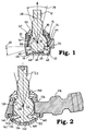
- Figure 1 shows a ball 10 on the end of a ball pin 12.
- the ball is received within a socket formed by a bore generally designated 14 in a substantially rigid socket body 16, the socket body 16 being part of a larger component.
- the socket 14 has an open end at 18 which, in the drawing, is closed by a cap 20.
- the assembled joint operates in a conventional manner.
- the spherical surface 22 of the ball moves against a low friction lining 24 which forms a spherical bearing surface in the socket to allow motion to be transferred between the ball pin and the socket body 16 irrespective of the relative angular positions of these components (within the designed range of angular movement within a cone having a substantially circular base).
- the ball is held in the socket by a first throat 30, where the diameter of the bearing surface 24 follows the curvature of the ball to an opening which has a diameter less than that of the ball.
- the opening or throat 30 is substantially circular, having a radius such as to allow the angular movement of the ball pin 12 through the range 26, but to limit this angular movement when the shank of the ball pin 12 comes into contact with an edge of the throat 30.
- the ball is also formed with a radially extending flange 32 and an adjacent groove 34. This flange extends beyond the spherical contour of the ball 10, the spherical contour being that defined by the centre point 36 and a radius 38. At the end of the ball opposite to the end of the pin 12, the ball has another spherical surface 40.
- the socket body 16 has an enlarged lower chamber 42, below the area which forms the bearing surface for the ball.
- An abutment ring 44 is fitted at the junction between the bearing surface 24 and the chamber 42.
- the flange 32 can move without obstruction within the chamber 42, but cannot move past the ring 44.
- the cap 20 When the joint is to be assembled, the cap 20 is not in place. First the low friction lining 24 is inserted into the bore 14 which forms the socket. Next the abutment ring 44 is fitted, and this clips into place within a recess within the socket body and this holds the lining 24 in place. The ball and ball pin component 10, 12 is then inserted, with the pin end being passed first through the socket body, from the lower end (as seen in the drawings) so that the pin passes through the throat 30, but so that the ball is retained within the bearing surface in the socket. Finally, the cap 20 is put into place and edges 46 of the socket body are swaged over the cap to hold it permanently in position.
- a bearing pad 48 on the inside of the cap 20 presses against the bottom of the ball 10, to keep the ball pressed firmly against the low friction lining 24.
- the bearing pad 48 and the bottom of the ball 10 have complementary spherical surfaces which have a common centre point 36 with the annular bearing surface 24 and the upper spherical surface 22 of the ball.
- a flexible sealing boot 50 is fitted over the ball pin 12 and around the top of the socket housing, in a conventional manner.
- the ball pin 12 can move through the arc indicated by the arrow 26, in any direction around the axis 28. In accomplishing this movement, there will be no play between the ball pin 12 and the socket body 16.
- the ball 10 has a flange 32 which, if the ball moves through the throat 30, will come into contact with the ring 44 to prevent further movement and in particular to prevent separation of the ball and the socket.
- the angle 45 subtended between the ring 44 and the flange 32 is one half of the angle indicated by the arrow 26, to ensure that the presence of the flange does not contribute to the limiting of the range of movement of the ball in the socket.
- the range of movement can be limited either by the abutment between the root of the stem 12 with the edge of the throat 30, or by the abutment of the flange 32 with the ring 44, or by a combination of these two features.
- the ball 110 of Figure 2 has a mushroom-shaped extension 132, with a stem 133 and a head 134.
- the extension 132 is rotationally symmetric with the ball 110 and the pin 112.
- the diameter of the head itself is slightly less than the diameter of the ball 110, and therefore the retention of the ball cannot be achieved by a ring put into place before the ball and its pin are inserted in the socket. Instead, the ball 110 is inserted in the socket, as previously described in connection with Figure 1.
- a retaining ring 144 is fitted into the open end of the socket.
- This ring has to surround the stem 133 and therefore may be made either in two parts or as an interrupted ring which can be moved to fit around the stem 133 before being seated on the seat 145.
- a cap 120 is then fitted and is held in place by swaging at 146.
- the outer face of the head 134 is spherical in form to fit comfortably against the pressure pad 148 which presses against the ball and keeps it in contact with the bearing surface 124.
- the spherical surfaces all have a common centre point 136.
Applications Claiming Priority (2)
| Application Number | Priority Date | Filing Date | Title |
|---|---|---|---|
| GB9712337 | 1997-06-14 | ||
| GB9712337A GB2326190A (en) | 1997-06-14 | 1997-06-14 | A ball joint |
Publications (2)
| Publication Number | Publication Date |
|---|---|
| EP0884489A2 true EP0884489A2 (de) | 1998-12-16 |
| EP0884489A3 EP0884489A3 (de) | 2000-01-19 |
Family
ID=10814110
Family Applications (1)
| Application Number | Title | Priority Date | Filing Date |
|---|---|---|---|
| EP98303793A Withdrawn EP0884489A3 (de) | 1997-06-14 | 1998-05-14 | Kugelgelenk |
Country Status (3)
| Country | Link |
|---|---|
| US (1) | US6099192A (de) |
| EP (1) | EP0884489A3 (de) |
| GB (1) | GB2326190A (de) |
Cited By (8)
| Publication number | Priority date | Publication date | Assignee | Title |
|---|---|---|---|---|
| WO2006110049A3 (en) * | 2005-04-12 | 2007-03-22 | Kongsberg Automotive As | Joining device for a vehicle's frame and a wheel axle |
| EP2295208A1 (de) * | 2005-04-20 | 2011-03-16 | Makita Corporation | Rotierendes Kraftwerkzeug |
| DE102013209493A1 (de) * | 2013-05-22 | 2014-11-27 | Behr Gmbh & Co. Kg | Gelenkverbindung |
| EP2998595A1 (de) | 2014-09-18 | 2016-03-23 | Rane (Madras) Limited | Ausfallsicheres kugelgelenk |
| WO2016170400A1 (en) * | 2015-04-24 | 2016-10-27 | Ndebele Paul | Ball joint with a retainer/safety nut that prevents accidental separation of the ball stud and the socket |
| WO2018127321A1 (en) * | 2017-01-06 | 2018-07-12 | Robert Bosch Gmbh | Ball joint with locking ball socket assembly |
| WO2019042661A1 (de) * | 2017-08-28 | 2019-03-07 | Zf Friedrichshafen Ag | Zentralgelenk für einen dreipunktlenker |
| EP3650719A3 (de) * | 2018-10-16 | 2020-07-29 | Dr. Schneider Kunststoffwerke GmbH | Lageranordnung, kugelgelenklager und anordnung mit einer lageranordnung und mindestens einem kugellager |
Families Citing this family (9)
| Publication number | Priority date | Publication date | Assignee | Title |
|---|---|---|---|---|
| DE19832956C2 (de) * | 1998-04-23 | 2002-07-11 | Zf Lemfoerder Metallwaren Ag | Gummigelagertes Kugelgelenk mit spannungsoptimierter Lagergeometrie |
| US6439794B2 (en) * | 2000-05-05 | 2002-08-27 | Federal-Mogul World Wide, Inc. | Compliant pivot socket for automotive steering |
| US6676325B2 (en) | 2000-05-05 | 2004-01-13 | Federal-Mogul World Wide, Inc. | Automotive steering compliant pivot socket with tapered head |
| BR0006443A (pt) * | 2000-12-12 | 2004-06-08 | Dana Industrial Ltda | Articulação esférica com sistema de restrição de movimento angular |
| US7048461B2 (en) * | 2002-09-20 | 2006-05-23 | Trw Inc. | Ball joint assembly with wear indication |
| US20060029461A1 (en) * | 2004-08-05 | 2006-02-09 | Trw Automotive U.S. Llc | Ball joint assembly with wear indicating electrical circuit |
| DE102006039863B4 (de) * | 2006-08-25 | 2009-07-09 | Zf Friedrichshafen Ag | Gelenkeinheit, vorzugsweise zur Lagerung des Fahrwerklenkers eines Kraftfahrzeuges |
| CN101408219B (zh) * | 2007-10-12 | 2013-04-24 | 鸿富锦精密工业(深圳)有限公司 | 转动定位结构 |
| US9309919B2 (en) * | 2013-03-28 | 2016-04-12 | Deere & Company | Sealed spherical joint |
Citations (5)
| Publication number | Priority date | Publication date | Assignee | Title |
|---|---|---|---|---|
| GB623506A (en) * | 1947-05-06 | 1949-05-18 | Jermyn And Pointer Ltd | Improvements in or relating to ball-joints |
| GB698473A (en) * | 1951-03-07 | 1953-10-14 | Thorleif Stokke | An improved ball and socket joint |
| US4679957A (en) * | 1986-06-10 | 1987-07-14 | Bauer John K | Ball joint safety system |
| US4749299A (en) * | 1987-05-26 | 1988-06-07 | Dana Corporation | Unitary compression member and wear indicator for a ball joint |
| WO1995033139A1 (en) * | 1994-05-31 | 1995-12-07 | Itt Automotive Electrical Systems, Inc. | Integral tophat linkball |
Family Cites Families (4)
| Publication number | Priority date | Publication date | Assignee | Title |
|---|---|---|---|---|
| US2860899A (en) * | 1954-09-17 | 1958-11-18 | Gottschald Rudolf | Universal joints |
| US4332500A (en) * | 1979-03-02 | 1982-06-01 | Gulf & Western Manufacturing Company | Tie rod ball joint construction |
| FR2487458B1 (fr) * | 1980-07-28 | 1985-12-06 | Perrier Jean | Liaison mecanique a rotule, a rattrapage automatique de jeu |
| DE3702277A1 (de) * | 1987-01-27 | 1988-08-04 | Trw Ehrenreich Gmbh | Kugelgelenk |
-
1997
- 1997-06-14 GB GB9712337A patent/GB2326190A/en not_active Withdrawn
-
1998
- 1998-05-14 EP EP98303793A patent/EP0884489A3/de not_active Withdrawn
- 1998-06-12 US US09/096,644 patent/US6099192A/en not_active Expired - Fee Related
Patent Citations (5)
| Publication number | Priority date | Publication date | Assignee | Title |
|---|---|---|---|---|
| GB623506A (en) * | 1947-05-06 | 1949-05-18 | Jermyn And Pointer Ltd | Improvements in or relating to ball-joints |
| GB698473A (en) * | 1951-03-07 | 1953-10-14 | Thorleif Stokke | An improved ball and socket joint |
| US4679957A (en) * | 1986-06-10 | 1987-07-14 | Bauer John K | Ball joint safety system |
| US4749299A (en) * | 1987-05-26 | 1988-06-07 | Dana Corporation | Unitary compression member and wear indicator for a ball joint |
| WO1995033139A1 (en) * | 1994-05-31 | 1995-12-07 | Itt Automotive Electrical Systems, Inc. | Integral tophat linkball |
Cited By (15)
| Publication number | Priority date | Publication date | Assignee | Title |
|---|---|---|---|---|
| JP2008537713A (ja) * | 2005-04-12 | 2008-09-25 | コングスベルイ オートモーティヴ アクティーゼルスカブ | 車両フレーム及びホイールアクスルの結合装置 |
| WO2006110049A3 (en) * | 2005-04-12 | 2007-03-22 | Kongsberg Automotive As | Joining device for a vehicle's frame and a wheel axle |
| DE112006000910B4 (de) | 2005-04-12 | 2024-03-21 | Kongsberg Automotive As | Verbindungsvorrichtung für einen Fahrzeugrahmen und eine Radaufhängung |
| EP2295208A1 (de) * | 2005-04-20 | 2011-03-16 | Makita Corporation | Rotierendes Kraftwerkzeug |
| DE102013209493A1 (de) * | 2013-05-22 | 2014-11-27 | Behr Gmbh & Co. Kg | Gelenkverbindung |
| EP2998595A1 (de) | 2014-09-18 | 2016-03-23 | Rane (Madras) Limited | Ausfallsicheres kugelgelenk |
| US10677284B2 (en) | 2015-04-24 | 2020-06-09 | Ndebele Paul | Ball joint with a retainer/safety nut that prevents accidental separation of the ball stud and the socket |
| WO2016170400A1 (en) * | 2015-04-24 | 2016-10-27 | Ndebele Paul | Ball joint with a retainer/safety nut that prevents accidental separation of the ball stud and the socket |
| WO2018127321A1 (en) * | 2017-01-06 | 2018-07-12 | Robert Bosch Gmbh | Ball joint with locking ball socket assembly |
| US11578752B2 (en) | 2017-01-06 | 2023-02-14 | Robert Bosch Gmbh | Ball joint with locking ball socket assembly |
| RU2767114C2 (ru) * | 2017-08-28 | 2022-03-16 | Цф Фридрихсхафен Аг | Центральный шарнир для трехточечного рычага подвески |
| US11345202B2 (en) | 2017-08-28 | 2022-05-31 | Zf Friedrichshafen Ag | Central joint for a three-point suspension link |
| WO2019042661A1 (de) * | 2017-08-28 | 2019-03-07 | Zf Friedrichshafen Ag | Zentralgelenk für einen dreipunktlenker |
| EP3650719A3 (de) * | 2018-10-16 | 2020-07-29 | Dr. Schneider Kunststoffwerke GmbH | Lageranordnung, kugelgelenklager und anordnung mit einer lageranordnung und mindestens einem kugellager |
| EP3832154A1 (de) * | 2018-10-16 | 2021-06-09 | Dr. Schneider Kunststoffwerke GmbH | Kugelgelenklager und kugelgelenkanordnung mit einem kugelgelenklager |
Also Published As
| Publication number | Publication date |
|---|---|
| GB2326190A (en) | 1998-12-16 |
| GB9712337D0 (en) | 1997-08-13 |
| EP0884489A3 (de) | 2000-01-19 |
| US6099192A (en) | 2000-08-08 |
Similar Documents
| Publication | Publication Date | Title |
|---|---|---|
| US6099192A (en) | Ball joint | |
| US9470259B2 (en) | Process for manufacturing a ball and socket joint and ball and socket joint manufactured according to the process | |
| CN109312775B (zh) | 插槽组件和制造插槽组件的方法 | |
| US5649779A (en) | Constant radial load ring for dust boot of a socket joint assembly | |
| US4154544A (en) | Pivot joint | |
| US6454484B1 (en) | Compliant pivot socket for automotive steering | |
| US7344311B2 (en) | Suspension joint bearing | |
| US6413003B1 (en) | Compliant pivot socket for automotive steering | |
| KR19990013517A (ko) | 드라이 웨지 볼/소켓 죠인트 | |
| US3374016A (en) | Ball joint | |
| US4347014A (en) | Hemispherical ball and socket joint | |
| US4749299A (en) | Unitary compression member and wear indicator for a ball joint | |
| EP1780430B1 (de) | Halteelement für nadelförmige Rollkörper für ein Gleichlaufgelenk | |
| CA1179853A (en) | Ball and socket joints | |
| US6726392B2 (en) | Ball joint with dual studs | |
| JP4514937B2 (ja) | ボールジョイント | |
| US4760860A (en) | Valve for tubeless tire | |
| US6871882B2 (en) | Ball-and-socket fluid coupling with primary and secondary retainer structures | |
| US4035094A (en) | Ball and socket joint | |
| US11739791B2 (en) | Ball joint and dust cover | |
| CN211778499U (zh) | 球窝组件和车辆中的实心车桥组件 | |
| EP3686447B1 (de) | Kugelgelenk und staubabdeckung | |
| CN111868396A (zh) | 改进的承窝组件及其制造方法 | |
| GB2080490A (en) | Homokinetic joint of the tripod type | |
| JP4170716B2 (ja) | トランスミッション・ジョイント用スパイダ組立体および対応するトランスミッション・ジョイント |
Legal Events
| Date | Code | Title | Description |
|---|---|---|---|
| PUAI | Public reference made under article 153(3) epc to a published international application that has entered the european phase |
Free format text: ORIGINAL CODE: 0009012 |
|
| AK | Designated contracting states |
Kind code of ref document: A2 Designated state(s): DE FR GB |
|
| AX | Request for extension of the european patent |
Free format text: AL;LT;LV;MK;RO;SI |
|
| 17P | Request for examination filed |
Effective date: 19981127 |
|
| PUAL | Search report despatched |
Free format text: ORIGINAL CODE: 0009013 |
|
| AK | Designated contracting states |
Kind code of ref document: A3 Designated state(s): AT BE CH CY DE DK ES FI FR GB GR IE IT LI LU MC NL PT SE |
|
| AX | Request for extension of the european patent |
Free format text: AL;LT;LV;MK;RO;SI |
|
| AKX | Designation fees paid |
Free format text: DE FR GB |
|
| 17Q | First examination report despatched |
Effective date: 20000912 |
|
| STAA | Information on the status of an ep patent application or granted ep patent |
Free format text: STATUS: THE APPLICATION IS DEEMED TO BE WITHDRAWN |
|
| 18D | Application deemed to be withdrawn |
Effective date: 20010123 |