EP0884245B1 - Method and apparatus for wrapping cylindrical articles with hot melt adhesive backed label - Google Patents
Method and apparatus for wrapping cylindrical articles with hot melt adhesive backed label Download PDFInfo
- Publication number
- EP0884245B1 EP0884245B1 EP98113681A EP98113681A EP0884245B1 EP 0884245 B1 EP0884245 B1 EP 0884245B1 EP 98113681 A EP98113681 A EP 98113681A EP 98113681 A EP98113681 A EP 98113681A EP 0884245 B1 EP0884245 B1 EP 0884245B1
- Authority
- EP
- European Patent Office
- Prior art keywords
- label
- drum
- adhesive
- article
- onto
- Prior art date
- Legal status (The legal status is an assumption and is not a legal conclusion. Google has not performed a legal analysis and makes no representation as to the accuracy of the status listed.)
- Expired - Lifetime
Links
Images


Classifications
-
- B—PERFORMING OPERATIONS; TRANSPORTING
- B65—CONVEYING; PACKING; STORING; HANDLING THIN OR FILAMENTARY MATERIAL
- B65C—LABELLING OR TAGGING MACHINES, APPARATUS, OR PROCESSES
- B65C9/00—Details of labelling machines or apparatus
- B65C9/08—Label feeding
- B65C9/18—Label feeding from strips, e.g. from rolls
- B65C9/1803—Label feeding from strips, e.g. from rolls the labels being cut from a strip
- B65C9/1815—Label feeding from strips, e.g. from rolls the labels being cut from a strip and transferred by suction means
- B65C9/1819—Label feeding from strips, e.g. from rolls the labels being cut from a strip and transferred by suction means the suction means being a vacuum drum
-
- B—PERFORMING OPERATIONS; TRANSPORTING
- B65—CONVEYING; PACKING; STORING; HANDLING THIN OR FILAMENTARY MATERIAL
- B65C—LABELLING OR TAGGING MACHINES, APPARATUS, OR PROCESSES
- B65C3/00—Labelling other than flat surfaces
- B65C3/06—Affixing labels to short rigid containers
- B65C3/08—Affixing labels to short rigid containers to container bodies
- B65C3/10—Affixing labels to short rigid containers to container bodies the container being positioned for labelling with its centre-line horizontal
- B65C3/12—Affixing labels to short rigid containers to container bodies the container being positioned for labelling with its centre-line horizontal by rolling the labels onto cylindrical containers, e.g. bottles
-
- B—PERFORMING OPERATIONS; TRANSPORTING
- B65—CONVEYING; PACKING; STORING; HANDLING THIN OR FILAMENTARY MATERIAL
- B65C—LABELLING OR TAGGING MACHINES, APPARATUS, OR PROCESSES
- B65C9/00—Details of labelling machines or apparatus
- B65C9/20—Gluing the labels or articles
- B65C9/24—Gluing the labels or articles by heat
- B65C9/25—Gluing the labels or articles by heat by thermo-activating the glue
-
- Y—GENERAL TAGGING OF NEW TECHNOLOGICAL DEVELOPMENTS; GENERAL TAGGING OF CROSS-SECTIONAL TECHNOLOGIES SPANNING OVER SEVERAL SECTIONS OF THE IPC; TECHNICAL SUBJECTS COVERED BY FORMER USPC CROSS-REFERENCE ART COLLECTIONS [XRACs] AND DIGESTS
- Y10—TECHNICAL SUBJECTS COVERED BY FORMER USPC
- Y10T—TECHNICAL SUBJECTS COVERED BY FORMER US CLASSIFICATION
- Y10T156/00—Adhesive bonding and miscellaneous chemical manufacture
- Y10T156/10—Methods of surface bonding and/or assembly therefor
- Y10T156/1002—Methods of surface bonding and/or assembly therefor with permanent bending or reshaping or surface deformation of self sustaining lamina
- Y10T156/1028—Methods of surface bonding and/or assembly therefor with permanent bending or reshaping or surface deformation of self sustaining lamina by bending, drawing or stretch forming sheet to assume shape of configured lamina while in contact therewith
- Y10T156/1033—Flexible sheet to cylinder lamina
-
- Y—GENERAL TAGGING OF NEW TECHNOLOGICAL DEVELOPMENTS; GENERAL TAGGING OF CROSS-SECTIONAL TECHNOLOGIES SPANNING OVER SEVERAL SECTIONS OF THE IPC; TECHNICAL SUBJECTS COVERED BY FORMER USPC CROSS-REFERENCE ART COLLECTIONS [XRACs] AND DIGESTS
- Y10—TECHNICAL SUBJECTS COVERED BY FORMER USPC
- Y10T—TECHNICAL SUBJECTS COVERED BY FORMER US CLASSIFICATION
- Y10T156/00—Adhesive bonding and miscellaneous chemical manufacture
- Y10T156/17—Surface bonding means and/or assemblymeans with work feeding or handling means
- Y10T156/1702—For plural parts or plural areas of single part
- Y10T156/1744—Means bringing discrete articles into assembled relationship
Definitions
- This invention relates to a method and apparatus for applying a label to a cylindrical article such as a crayon with a heat activated adhesive backed label.
- Crayons are typically made from a soft material such as paraffin wax, which is impermeable to moisture but sometimes difficult to wrap with a label because the crayon's surface is slick, making adhesive adherence difficult.
- crayons and other similar articles are sometimes tapered about 0.127 mm to 0.254 mm (0.005 to 0.010 inches) over their 5.08 cm to 10.16 cm (two to four inch) length. This taper makes application of a label to the crayon even more difficult because the label ends often will not align together due to the taper.
- a precut label having an inexpensive flour based adhesive on one side thereof is placed over a slot.
- the crayon is laid on the label and pushed into the slot.
- the label is bent around the crayon and then the crayon is rolled at least about one revolution to wrap the label about the crayon.
- the crayon and moist adhesive must then be allowed to dry.
- the machines used for labelling these crayons in accordance with this prior art method produce about 180 crayons a minute.
- US-A-2 613 007 discloses a label applying drum where labels having an heat-activated adhesive are activated by a stream of hot air from a small nozzle.
- a label is applied onto a substantially cylindrical article using a label drum to feed labels to an article wrapping position where cylindrical articles are labeled.
- a thin layer heat activated adhesive backed label is fed onto the surface of the label drum so that the adhesive back faces outward from the drum.
- the adhesive is heated as the drum rotates so that the adhesive obtains a sufficient temperature to melt.
- Substantially cylindrical articles such as crayons
- a hopper and chute located at the top portion of the label drum into a serpentine track, and then into a star wheel transfer assembly which rotates and guides the crayons onto the surface of the label drum.
- the label film is fed through a dancer and feed roll assembly and then fed to the bottom portion of the label drum into a cutting roll assembly where the film is cut and transported as cut labels onto the drum.
- labels move upward into an article wrapping position located at the top portion of the label drum at the point where the articles are discharged from the serpentine track and star wheel transfer assembly.
- the article feed mechanism in one aspect of the present invention has many different transfer points such as from the hopper into the serpentine track and to the star wheels. These transfer points may create bottlenecks during high production speeds. It would be desirable if an article feed system could be used which facilitates operator inspection, such as a conveyor unit oriented near the bottom of the label drum and has fewer transfer points, such as a straight linear track, as compared to a system using a large number of transfer points. Fewer transfer points would also allow greater control over article feed and simplify delivery. It would also be desirable to have a bottom feed unit where the taper of articles can be compensated.
- an apparatus applies a label to a substantially cylindrical article such as a crayon and has a label drum which is rotated by a main drive mechanism.
- a label feed mechanism includes a cutting drum and feeds a thin layer, heat activated adhesive backed strip of label material onto the surface of the cutting drum, which cuts the strip into label segments and feeds them onto the label drum so that the adhesive back faces outward from the drum.
- the adhesive is heated as the label drum rotates so that the adhesive obtains a sufficient temperature to melt.
- Substantially cylindrical articles such as tapered crayons are conveyed into tangential spinning engagement with the drum and into rotative engagement with the leading edge of the label as the label moves into an article wrapping position so that the label wraps about the crayon and adheres thereto.
- the cylindrical articles i.e. crayons, may be about two to four inches long and tapered along their length by about 0.127 to 0.254 mm (0.005 to 0.010 inches).
- the articles are conveyed into tangential spinning engagement with the drum and into engagement with the leading edge of a label at a skewed angle so that the label wraps about the tapered article with end-to-end alignment thereof.
- the wider "butt" end of the article engages the leading edge of the label before the more narrow end.
- a star wheel transfer assembly can be used to convey the articles onto the drum surface. The articles are held in article holding notches of the starwheel in a skewed configuration.
- the label drum may include orifices located at an area of the drum surface where a label is positioned. Vacuum is drawn through the orifices for retaining the label on the drum surface as the drum rotates. Air is then blown through the orifices underlying the leading edge of the label to blow the leading edge of the label onto the article at the article wrapping position.
- a heat source initially heats the adhesive and ensures that the hot melt adhesive has obtained a sufficient temperature to melt so that it adheres to the cylindrical article and to the label overlap when wrapped.
- the articles can be a wide variety of different articles such as a wax crayon.
- the hot melt adhesive layer positioned on the label is about 12.7 ⁇ m to 25.4 ⁇ m (0.0005-0.001 inches) thick. It has been found that a low temperature hot melt adhesive having a melting range of about 140 to about 170 degrees Fahrenheit is sufficient for use with the invention.
- Typical adhesives could include Findley Adhesives Inc. 300-634 and H.B. Fuller Company HM-0727 hot melt adhesives.
- pressure may be imparted onto the article as it is wrapped.
- a pressure plate is positioned adjacent the article wrapping position and it is biased into engagement with the article.
- the camber of the pressure plate is varied relative to any articles conveyed on the surface of the drums so as to impart a side-by-side differential pressure against an article during labelling to ensure end-to-end label alignment over the article.
- the pressure plate is adjustable for varying the wrapping pressure of the label on the article.
- a preferred crayon formed by this process of the present invention includes a cylindrical crayon body that is tapered along its length having a butt end with a diameter that is at least about 0.127 mm (0.005 inches) larger than its opposing end.
- the hot melt adhesive backed label is wrapped circumferentially about the crayon body.
- the label has leading and trailing edges and the leading edge is applied onto the crayon body at a skewed angle relative to the longitudinal axis of the body so that the label is wrapped circumferentially about the crayon body with end-to-end label alignment.
- the adhesive adheres the label to the crayon body and to the label overlap. Rotation under the pressure pad after wrapping of the label cools the adhesive.
- the apparatus may include a label drum which defines an article wrapping position at the lower portion of the drum.
- a label feed mechanism feeds a thin layer, heat activated adhesive backed label onto the surface of the drum so that the adhesive back faces outward from the drum.
- the drum is rotated to move the label retained thereon into the article wrapping position.
- a hot blower heats the adhesive as the drum rotates so that the adhesive obtains a sufficient temperature to melt.
- Cylindrical articles are conveyed substantially horizontally along a predetermined path of travel defined by a conveyor and into the article wrapping position located at the bottom portion of the label drum and into rotative engagement with the label retained on the label drum so as to transfer the label onto the cylindrical article by wrap-around labelling.
- the article is conveyed along a substantially arcuate path around the lower portion of the label drum and into engagement with the label.
- the labels may be fed from a position located adjacent the upper portion of the label drum.
- the label feed mechanism includes a label strip feeder and a label strip cutter for cutting the strip of label material into rectangular sized labels, and a mechanism for feeding the cut labels onto the surface of the drum.
- the conveyance system includes a horizontally configured conveyor, which has article carriers positioned thereon for conveying an article to the article wrapping position.
- the article carriers can be biased upward toward the label drum for exerting pressure onto the articles during labeling. Additionally, the side-to-side pressure of the article carriers can be changed for changing the camber of the articles during labeling to help ensure end-to-end label alignment on the articles.
- Each of the article carriers may comprise spaced rollers for supporting an article on the conveyor.
- the rollers include outwardly extending pins with brass bearing members.
- Two opposing guide plates are positioned at the lower portion of the label drum adjacent the article wrapping position and include grooves for receiving the pins in a predetermined arcuate path so that the carriers and articles thereon are conveyed in an arcuate path around the lower portion of the label drum.
- the guide plates can be supported on bearings, such as Thompson Bearings, so that the guide plates can be raised and lowered.
- Means is located at either guide plate to allow one guide plate to be raised higher than the other, thus allowing greater pressure to be applied on one side of the crayon. In this manner, the article taper can be compensated to allow end-to-end label alignment.
- a preferred crayon formed by this process of the present invention includes a cylindrical crayon body that is tapered along its length having a butt end with a diameter that is at least about 0.127 mm (0.005 inches) larger than its opposing end.
- the hot melt adhesive backed label is wrapped circumferentially twice about the crayon body.
- the label includes printed indicia and a registration mark used for determining cut points on the label. The registration mark is positioned such that when the article is labeled, the registration mark is covered and a desired printed indicia is exposed.
- the label has leading and trailing edges.
- the leading edge can be applied onto the crayon body at a skewed angle relative to the longitudinal axis of the body so that the label is wrapped circumferentially about the crayon body with end-to-end label alignment.
- the adhesive adheres the label to the crayon body and to the label overlap. Rotation against the label drum after wrapping of the label cools the adhesive.
- a label can be applied onto a substantially cylindrical article using a conveyor that supports the article on a substantially horizontal chain conveyor formed of two chain loops each formed from a plurality of interconnected chain links.
- Substantially parallel support rods extend between the chain loops and support the chain links. The support rods are spaced at a distance sufficient to allow an article to rest thereon.
- the labels are transferred onto the cylindrical article by wrap around labeling.
- the present invention provides a method and apparatus for applying a label onto a substantially cylindrical article as defined by claims 1 and 5 respectively.
- Figures 1 through 12 shows the machine with articles feed along a serpentine to the top part of the label drum.
- Figures 13 through 20 illustrate a second embodiment using a bottom feed unit and an article with a printed indicia and registration mark, Figures 19 and 20.
- Figures 21 through 24 illustrate a third embodiment where the bottom feed unit comprise a chain conveyor.
- FIG. 10 a schematic, overall illustration of the apparatus for applying a label onto a substantially cylindrical article such as tapered crayon wherein the label has seams aligned end-to-end on the article ( Figure 12).
- the labels are thin layer, heat activated adhesive backed labels typically having at least one layer of paper with the adhesive applied evenly on one side. Throughout this description, the labels will be referred to by the letter "L.”
- the apparatus 10 may be used for applying a label to different tapered and nontapered articles and crayons requiring good end-to-end alignment of the label ends and high production speeds, which the apparatus and method of the present invention can provide.
- the apparatus 10 is suitable for high quality cylindrical labelling of different articles requiring the application of thin labels having a thickness typically less than about 0.127 mm (0.005 inches).
- the cylindrical articles on which the labels are applied will be referred to as crayons and will be illustrated as such and given the reference letter "A.”
- the illustrated crayons are typically formed from paraffin wax, and have a surface which is smooth and slick, making it resistant to water and some adhesives.
- the crayons are tapered, having one end about 8.18 mm (0.322 inches) diameter and the other end about 7.96 mm (0.314 inches) diameter, giving a taper of 0.178 mm (0.007 inches) from the wide "butt" end 14 of the crayon to the more narrow end 16 .
- the crayons typically are about two to four inches long.
- the label material applied to the illustrated crayons typically includes one layer of paper which is coated completely on one side with the heat activated adhesive.
- the paper can be a coarse grain paper which is inexpensive, but economical and practical considering the numerous crayons which are labelled.
- the heat activated adhesive layer is applied at about a one half to one mil coating thickness i.e., 12.7 to 25.4 ⁇ m (0.0005-0.001 inches).
- the adhesive is a low temperature heat activated adhesive which melts at a temperature range of about 60°C to 76.67°C (140 to 170 °F). Typical examples include a hot melt adhesive sold by Findley Adhesives, Inc.
- the label materials may be initially supplied as a roll 18 of strip label material "S" which can be positioned on a mandrel 22 of a feeder assembly indicated generally at 24.
- a double mandrel 22, 23 each holds a roll 18.
- the other roll 18 on mandrel 23 then is fed which maintains production.
- the strip "S” of label material is then fed through a feedroll assembly, indicated generally at 26 , and to a cutting drum assembly, indicated generally at 28 , which is operatively connected to the main drive motor and transmission assembly 30 of a label transport drum indicated generally at 32 .
- a registration and sensing system 34 sense label indicia to ensure proper cutting on the strip and ensure quality cutting of the labels.
- the registration can include a FIFE label edge registration control sensing system for printed label registration marker.
- the feedroll assembly 26 includes a dancer roll assembly 36 and feedrolls 38 which move the strip S into the cutting drum assembly 28 .
- the label transport drum 32 typically is supported on a frame assembly 40 .
- the main drive motor and transmission assembly 30 is supported by the frame 40 and rotates the label transport drum 32 as well as the cutting drum assembly by a suitable transmission 42 .
- the cutting drum assembly 28 includes a cutting roll 44 which is mounted to the machine frame 40 and positioned adjacent the label transport drum 32 at a lower portion thereof as shown in Figure 1. The cutting roll 44 cuts the label strips into segments, i.e., labels, which are then fed onto consecutive label receiving positions, indicated at 46, of the label transport drum 32.
- Each label moves with the rotating drum 32 into a heat tunnel, indicated at 48 , where the adhesive is melted, and then into an article wrapping position, indicated at 50, where crayons are fed into tangential spinning engagement with the drum surface and into rotative engagement with a leading edge of the label "L" as the label moves into the article wrapping position so that the label wraps about the crayon and adheres thereto by means of the melted adhesive.
- the wrapped crayons are then discharged into a discharge chute 52.
- a label drum is rotatably received over a central hub 62 .
- respective first and second radially extending, slotted vacuum manifolds 64, 66 and blow-off manifolds 68, 70 are formed on the outer surface of the hub 62 .
- the vacuum and blow-off manifold at 64, 68 of Figure 8 are aligned circumferentially with each other, as are the manifolds 66 , 70 of Figure 9 with each other.
- Respective sources of vacuum and pressure (shown schematically at 72, 74, Figure 1) operatively connect to horizontal vacuum manifolds 72a , and gate manifolds 72b , and horizontal pressure manifolds 74a , and gate manifold 74b .
- An air pressure manifold 76 provides air against a leading edge of a label.
- the second vacuum manifold extends a further arc distance 79 than the first vacuum manifold 64 .
- the second vacuum manifold 66 retains the label on the drum surface if a label is not transferred onto an article.
- the blow-off manifolds 68, 70 exert pressure on the label to blow it from the drum surface. Further details of a hub and drum label construction which can be used in the present invention are set forth in US-A-5,344,519.
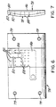
- Each insert plate 78 is rectangularly configured ( Figure 6), and has a top surface that is configured substantially similar to the curvature of the drum surface. Screws 79 can secure the plates 78 to the drum 60 and be used on every plate 78 or every other plate, with every other unscrewed plate held by contiguous screwed plates.
- the under surface of each insert plate includes two plenums formed in the surface as shown in Figure 6.
- a first plenum 80 is formed on the undersurface and has orifices 82 extending upward which communicate with a surface of the insert plate at that area where the leading edge of a label is to be positioned. The first plenum communicates with a port 84 in the drum 60 which is positioned in circumferential alignment with the first vacuum manifold 64 and pressure manifold 76.
- a second plenum 86 is formed in the undersurface and has orifices 88 extending upward therethrough to communicate with the surface of the insert plate at an area where the trailing edge and midportion of the label are positioned.
- the second plenum 86 extends to a port 90 of the drum which is aligned circumferentially with the second vacuum manifold.
- Each insert plate has a resilient pad 92 ( Figures 2, 3, 5, and 7) placed over a substantial portion of the outer surface of the insert plate.
- the orifices 82, 88 are formed within the resilient pad.
- the resilient pads 92 can be formed preferably from silicone or other similar material.
- the pads 92 are contiguous with each other ( Figures 3 and 5) and form a soft cushion on which the crayon rolls during wrapping and also form a smooth surface on which the label lies as the label moves from its initial position after cutting when it is first fed onto the drum surface and then moves into the article wrapping position 50 ( Figure 2).
- the silicone pads 92 act somewhat as a cushion, the crayon is deflected slightly into the cushion material by means of a pressure applicator, indicated at 96, so as to create a "footprint" in the soft cushion material. During crayon wrapping, the air is squeezed out between the crayon, label and pad surface, allowing better wrapping of the label about the crayon. Additionally, the silicone pads 92 have greater friction between the crayons in the drum surfaces compared to steel or an aluminum surface so that less pressure need be applied by the pressure applicator.
- the label retaining insert plates 78 are limited in the illustrated embodiment to about a 11.43 cm (four and one-half inch) long label corresponding to about 11.43 cm (four and a half inch) wide insert plate. This has been found adequate for labelling most conventional crayons and other similar articles.
- the insert plates 78 can be made deeper and fewer in number, and thus longer along the arcuate portion of the top surface since the plate is longer and has a longer surface length on which the arc extends. However, the length is still limited because too deep an insert plate 78 would interfere with the drum rotation about the hub. A larger label drum 60 and hub 62 would have to be constructed. Further details of one example of the plate construction which could be used for the present invention can be found in US-A-5 344 519.
- the label transport drum 32 rotates and moves the label into the heat tunnel 48 where the adhesive is heated to its melting point.
- the heat time is about 0.25 seconds.
- the heating tunnel 48 is defined by two opposing side bracket plates 102, 104, a front and rear end plate 106, 108 and a top cover plate 110 , and forms a heat tunnel positioned closely adjacent the surface of the label transport drum in a position before the article wrapping position as shown in Figure 2.
- Two high powered ceramic heater and blower assemblies 112, 114 are mounted on the top plate 110 at the front and rear portions. Both heaters produce a 538°C (1,000°F) blast of hot air.
- the first rear heater 114 amplifies and heats the heat activated adhesive
- the second front heater 112 amplifies that heat to ensure that the hot melt adhesive melts adequately.
- the total time in which the label is contained within the heat tunnel is about 0.25 seconds, and corresponds to the high operating speeds of about 500 to 600 crayons per minute.
- Temperature sensors 115 preferably thermocouples, sense temperature in the heating tunnel 48.
- the heater and blower assemblies 112, 114 then are adjusted accordingly.
- the system can be temperature controlled through a closed loop controller.
- the labels then continue into the article wrapping position 50 where they engage the crayons which had been fed from a hopper 120 positioned at the top portion of the frame 40 ( Figure 1).
- the crayons are retained in the hopper 120 and a large gear 122 positioned at the lower discharge end of the hopper grabs a crayon at the eleven o'clock position and rotates it approximately ninety degrees to release it into a serpentine guide 124 .
- the crayons continue downward through the serpentine guide 124 , through a gate 126, and into a double star wheel assembly indicated generally at 128 .
- the gate 126 between the serpentine transfer and first starwheel transfer roll is formed of latex rubber and soft enough so that it does not break the crayon it engages.
- the gate 126 is normally biased in the closed position to prevent crayons from moving from the serpentine into the first starwheel transfer roll.
- a cylinder 126a actuates a piston 126b which raises the gate 126 to allow transfer of crayons from the serpentine 124 into the article receiving positions of the first starwheel.
- the serpentine transfer 124 has an inner and outer rail 124a, 124b .
- the spacing between the inner rail 124a has a larger gap than the spacing of the outer rail 124b to accommodate the taper of the crayons A ( Figure 1A ).
- the double starwheel assembly 128 can be driven off the main drive system or a separate drive system and only for the starwheel assembly.
- the starwheel assembly includes two starwheels.
- Article receiving slots 140 of the first star wheel 130 receive the crayons and transfer them into the second star wheel 132 .
- the second star wheel has its article receiving slots 142 formed such that the article, i.e., crayon, is slightly skewed about 0.5 degrees (angle X°) within the slots ( Figure 10). This skewing can be accomplished by forming the slots 142 so that the crayon lies skewed therein, or by using inserts (not shown) which skew the crayon when positioned within the slot 142.
- the crayon moves downward into tangential spinning engagement with the drum surface and into engagement with the leading edge of a label at a skewed angle.
- the crayons are conveyed onto the drum surface so that the wider "butt" end 14 of a crayon first engages the leading edge of a label before the opposing end. This effectively compensates for the taper of the crayon.
- the leading edge ports 84 in the drum are aligned with each insert plate and move over the pressure manifold 76. The jet of the leading edge of the label air from the manifold forces outward into engagement with the crayon.
- the pressure applicator 96 imparts pressure to the crayon as it is wrapped.
- the pressure applicator 96 includes a pressure plate 140 (Figure 2) that has a bottom surface engaging the crayon.
- the pressure plate 140 is spring biased and supported by a second support plate 142 fixed to the frame.
- Two respective pinion gears 144, 146 are positioned on the support plate 142 and mesh with each other.
- the pinion gears 144, 146 have threaded central shafts which engage the spaced pressure plate 140.
- a third gear (not shown) engages both pinion gears 144, 146, and is rotatable by a handle-shaft 148.
- the third gear turns both gears so that they rotate in opposite directions, thus biasing the pressure plate against the side of the crayon.
- the amount of biasing force against the ends of the crayon determines how much the label can be aligned.
- the pressure plate 140 can also be adjusted closer or farther from the label transport drum, which varies the pressure of wrapping the label on the article. Also, the crayon, once wrapped, is rolled further under pressure from the pressure plate which further cools the adhesive.
- the label then wraps around the crayon and the adhesive cooled as it rolls and then moves into the discharge chute 52 where it is then transferred into an article conveyor 150. Because the label engaged the "butt" end of the crayon first during wrapping, the taper is compensated for with the result that the label ends are aligned ( Figure 12). Without skewing the article slightly, the label ends would not be aligned.
- the resilient pads 92 can become very hot during high speed operation, especially materials like silicone, and therefore a bank of airjets 152 are positioned after the discharge chute 52 . These jets blow high speed air onto the silicone pads to cool same.
- a compressed air source and lines 154 provide the necessary air flow.
- a controller 156 is mounted as a movable swing arm 158 and controls machine operation. It can be easily swung out of the way.
- a strip S is initially fed from a feed roll 18 into the feed roll assembly 26 and cutter drum assembly 28 .
- the registration and sensor unit maintains proper registration of any label indicia with the cutting drum so that labels are properly cut at proper indicia and transferred exactly onto the label retaining positions 46 of the label transport drum 32 .
- the drum rotates and moves labels through the heating tunnel 48, and then into the article wrapping position 50 where the leading edge of the label is forced upward into engagement with the skewed crayon, which has been fed from the second transfer roll.
- the butt end of the crayon engages the leading edge of the label first, the label is wrapped and has end-to-end alignment of labels.
- the crayon then moves to a point where it is discharged into the chute and then transferred onto the conveyor.
- FIG 10 a schematic, overall illustration of the apparatus for applying a label onto a substantially cylindrical article such as tapered crayon wherein the label has seams aligned end-to-end on the article ( Figure 19) by using a bottom feed conveying unit, illustrated generally at 12.
- the bottom feed conveying unit 12 of this embodiment of the present invention allows an operator to visually inspect articles during advancement into an article wrapping position.
- the machine of the present embodiment can work with the labels that are thin layer, heat activated adhesive backed labels typically having at least one layer of paper with the adhesive applied evenly on one side.
- the label material typically includes printea indicia 17b which will be exposed after wrapping.
- a registration mark 17a can be included on the label material. This registration mark 17a is sensed by registration sensors during film feed to ensure proper cutting of the label at the desired point.
- a crayon or other article is double wrapped ( Figure 20a), and the registration mark 17a covered.
- the printed indicia 17b such as advertising and date codes, is exposed.
- the label materials can be initially supplied as a roll 18 of strip label material "S" which can be positioned on a mandrel 22 of a feeder assembly indicated generally at 24.
- a double mandrel 22, 23 each holds a roll 18.
- the strip "S” of label material is then fed through a feedroll assembly, indicated generally at 26 , and to a cutting drum assembly, indicated generally at 28 , which is operatively connected to the main drive motor and transmission assembly, indicated generally at 30, of a label drum indicated generally at 32 .
- the cutting drum assembly 28 is located so that label material is fed and cut at the upper portion of the label drum 32 .
- the label moves into an article wrapping position 33 located at the bottom portion of the label drum 32 where the articles are fed from the conveying unit 12.
- a registration and sensing unit 34 senses the label registration mark to ensure proper cutting of the strip on the desired cut line and ensure quality cutting of the labels.
- the cutpoint on the strip label is based on the registration point.
- the registration and sensing unit 34 can include a FIFE label edge registration control and an optical system for reading printed label registration markers.
- the feedroll assembly 26 includes a dancer roll assembly 36 and feedrolls 38 which move the strip S into the cutting drum assembly 28 .
- the label drum 32 typically is supported on a frame assembly 40.
- the main drive motor and transmission assembly 30 is supported by the frame 40.
- the motor 41 rotates the label transport drum 32 by a suitable transmission 42.
- the drive motor and transmission 30 rotates the label drum in a clockwise direction.
- the cutting drum assembly 28 includes a cutting roll 44 which is mounted to the machine frame 40 and positioned adjacent the label transport drum 32 at an upper portion thereof as shown in Figure 13.
- the cutting roll 44 has a carbide knife 45 positioned thereon ( Figure 14) which cuts the label strip into rectangular segments, i.e., labels "L", having leading and trailing edges, L1, L2.
- the leading edge L1 is transferred onto a label receiving position, indicated at 46, of the label transport drum 32. ( Figures 14 and 15).
- the rest of the label then transfers to the label drum.
- the roll 44 is rotated by a transmission 44a driven from the label drum 32 .
- the vacuum roll 44 can include vacuum draw which originates from a vacuum hose 44b connected to an internal manifold and orifices of the vacuum roll.
- the cutting roll 44 can include a carbon steel substrate formed at the periphery of the roll and can be received over a central mandrel.
- the surface of the cutting roll 44 may be enhanced.
- a nickel alloy coating is deposited onto the substrate and has micropores.
- a polytetrafluoroethylene (Teflon) polymer is integrated within the nickel alloy coating to form an integrated surface layer of about 25.4 to 50.8 ⁇ m (0.001 to 0.002 inches).
- the integrated surface layer has a surface hardness of about 65 to 68 Rockwell C scale. This surface has a coefficient of friction of about 0.03 (with 8 or lower RMS) so as to reduce the tendency of the label to build static and to aid in label transfer from the cutting drum onto the label drum.
- the cutting roll 44 with this surface has an operating heat resistance range of about -101.11 to 510°C (-150 to +950°F).
- the integrated surface can be formed by a coating process known commercially by the trade designation Magnaplate HMF and provided by General Magnaplate Corporation, 1331 Route 1, Linden, New Jersey 07036.
- the substrate is pretreated and the nickel alloy is deposited on the substrate surface. Micropores are enlarged and the Teflon infused into the surface layer. The Teflon then is integrated within the layer.
- the cutting roll has improved durability and anti-static electrical properties.
- the impregnated surface layer imparts dielectric resistance, a low dissipation factor, and very high surface resistivity. It is believed that the surface resistivity is about 60 micro ohm/cm over a wide range of frequencies.
- the impregnated surface layer also has corrosion resistance. Salt spray per ASTM B-117 exceeds 336 hours when the thickness is 25.4 ⁇ m (0.001 inches) or greater.
- the cutting roll 44 is positioned adjacent the drum and a stationary knife 45a ( Figure 13) engages the cutting knife 45 to cut labels.
- a stationary knife 45a Figure 13
- on-drum cutting can be used where the knife 45 engages a hardened surface of the label drum.
- An example of such cutting system is disclosed in US-A-5,350,482 to Westbury. The choice of cutting method depends on the labels used, the speed of operation, operator demands, as well as other factors related to the type of labeling operation.
- a static eliminator 47 ( Figure 13) can be positioned just after the cutting drum assembly 28 .
- the static eliminator 47 is beneficial because it reduces the heavy charge build-up. This can be critical because in very low humidity conditions the charge contained on the label causes the-labels to stick to the surface of the cutting roll 44.
- the static eliminator 47 eliminates this charge which allows the label to transfer efficiently to the label drum 32 .
- Each label moves with the rotating label drum 32 into a heating tunnel, indicated at 48, where the adhesive is melted, and then into the article wrapping position 33 , located at the bottom portion of the label drum 32 , where crayons or other articles are fed by the conveying unit 12 into tangential spinning engagement with the drum surface and into rotative engagement with a leading edge L1 of the label "L" as the label moves into the article wrapping position 33.
- the label wraps about the crayon twice and adheres thereto by means of the melted adhesive.
- the wrapped crayons are then discharged into a discharge chute or discharge conveyor assembly illustrated generally at 52 ( Figure 13).
- Figures 1 through 12 illustrate silicone pads 92 .
- the silicone pads 92 act somewhat as a cushion, the crayon is deflected slightly into the cushion material by means of upward pressure exerted by the conveying unit against the crayon and label drum 32 , so as to create a "footprint" in the soft cushion material.
- the air is squeezed out between the crayon, label and pad surface, allowing better wrapping of the label about the crayon.
- the silicon pads 92 have greater friction between the crayons in the drum surfaces compared to a steel or an aluminum surface so that less pressure need be applied by the upward biasing pressure of the conveyor.
- the heaters 112, 114 can be pivotally mounted on shafts 112a, 114a or on a slide plate (not shown) so that respective heaters can be pivoted or moved out of proximity to the label drum ( Figure 13).
- the crayons are retained in a hopper, indicated at 120 , spaced from the label drum.
- the hopper 120 includes a basin 122 with an inclined floor in which the crayons are contained.
- the lower portion of the basin has a through channel 124 which feeds into a large vacuum wheel 126 positioned at'the lower discharge end of the basin and grabs a crayon at the 12:00 position, holds the crayon with its formed slots by vacuum and rotates it approximately 180 degrees to release it onto a carrier, indicated generally at 130, of the conveyor.
- the vacuum wheel 126 includes a source of vacuum (not shown) for retaining the crayons within the slots formed in the wheel.
- a sensor 132 indicates when a carrier 130 is approaching the drop off point of the vacuum wheel and signals to a controller 140 the sensed location of the carrier. Vacuum wheel rotation is then timed so that the crayon is dropped onto the carrier 130 when the carrier is opposite the drop off point defined by the lower-most point of the vacuum wheel 126 . Vacuum wheel rotation can be controlled by a drive mechanism 134 which operatively connects to the sensor 132 via circuitry 136 and the controller 140 .
- the conveyor 12 includes a distal drive wheel 144 mounted to the frame 40 and a first proximal drive wheel 146 adjacent the article wrapping position.
- An endless, looped and lugged conveyor belt 148 is coupled about the two drive wheels, which also are geared to receive the lugs 148a of the belt ( Figure 14).
- the proximal drive wheel 146 is mounted on a support shaft 146a rotatably mounted between shaft supports 147 fixed to the frame 40.
- the distal drive wheel 144 includes a gear linkage (indicated generally at 149) which is geared to the label drum drive with a clutch mechanism for overload protection.
- a drive motor could drive the distal drive wheel 144 to move the conveyor 148.
- the controller 140 could operatively connect to the motor to allow an operator to control the conveyor.
- Carriers 130 are spaced two inches apart on the belt 148. (For purposes of illustration, Figure 14 illustrates only one carrier and Figure 13 has only part of the belt showing carriers 130 .) Each carrier is about four inches wide corresponding to the width of the conveyor belt 148.
- the carriers are supported and secured to the belt 148 by threaded fasteners (not shown) extending through the bottom portion of the carrier and extending into fastening plates 150 secured onto the belt 148.
- the plates 150 include threaded holes 151 which receives bolts (not shown) for holding the carriers 130 .
- the plates 150 can be configured to allow different configured carriers to be secured to the belt to accommodate different articles (Figure 16).
- each carrier 130 includes roll supports 152 which support two rolls 154, 156 on which a crayon rests.
- the rollers 154, 156 are preferably formed as Nilotron rollers, although other materials can be used if the materials can hold up to wear.
- Each roll has outwardly extending shafts 154a, 156a and a brass bearing member 154b, 156b, rotatably positioned over each shaft 154a, 156a.
- the members 154b, 156b are freely rotatable thereon.
- the shaft and members 154a , b , 156a, b enter a groove 160 of respective parallel spaced guide plates 162 at the article wrapping position 33.
- the carriers 130 follow the arcuate configured groove 160 so that the carriers 130 move around the lower portion of the label drum 32. This allows a crayon within the carrier 130 to engage the surface of the label drum throughout its lower periphery.
- a rigid support surface 166 is located underneath the conveyor belt 148 proximal to the article wrapping position at a point where the conveyor approaches the label drum so that the carriers 130 will not exert downward pressure on the conveyor belt and cause slack, which could create error during labeling.
- the guide plates 162 are each mounted on two Thompson Bearings 167 which allows the guide plates to be raised and lowered independently of each other.
- the Thompson Bearings 167 rest on a horizontally configured support plate 168.
- the Thompson Bearings include a shaft 170 received within a bearing housing 171 as is conventional.
- Two jack screws 172 are positioned on either side of the article wrapping position 33 and rest on the support plate 168 .
- the jack screws 172 raise the guide plates 162 toward the label drum and move the carriers 130 closer toward the surface of the label drum, thus engaging the crayons carried thereon into engagement with the surface of the label drum.
- the amount that the jack screws 172 are turned corresponds to the desired pressure on the crayon during labeling.
- the jack screws 172 can be turned to vary the camber of the article relative to the label to aid in ensuring end-to-end alignment during labeling.
- the jack screws 172 can be hydraulically operated coupled to a motor and drive mechanism (not shown in detail) so that an operator can readily control the camber and pressure of the crayon during labeling via the controller 140 .
- the support plate 168 is supported on a mounting plate 176 at each corner by jack screws 177 .
- the support plate 168 is gimbled at the center so that the camber of the support plate 168 can be varied.
- the mounting plate 176 is closely spaced to the support plate 168. Small, finite adjustments in the camber of the support plate 168 relative to the mounting plate 176 are made by individually turning desired jack screws 177.
- the labels then continue into the article wrapping position 33 where they engage the crayons advancing along the article conveyor 12.
- the crayons are conveyed onto the drum surface so that the crayon engages the leading edge of a label.
- the leading edge ports 84 in the drum that are aligned with each insert plate move over the pressure manifold 76 .
- the jet of air from the manifold forces outward the leading edge of the label into engagement with the crayon.
- the label then wraps around the crayon twice and the adhesive is cooled as it rolls. During labeling side-to-side pressure on the crayon is varied to compensate for crayon taper. The original registration mark 17a is covered and printed indicia present on the label exposed. The crayon then moves into the discharge chute or conveyor 52.
- the resilient silicon or similarly formed pads 78 can become very hot during high speed operation, and therefore a bank of airjets 180 ( Figure 15) are positioned on the label drum side opposing the heater assembly. These jets 180 blow high speed air onto the silicone pads to cool same. A compressed air source and lines 182 provide the necessary air flow.
- a strip S is initially fed from a feed roll 18 into the feed roll assembly 26 and cutter drum assembly 28.
- the registration and sensor unit maintains proper registration of any label points with the cutting drum so that labels are cut at proper points and transferred exactly onto the label retaining positions 46 of the label transport drum 32 .
- the drum rotates and moves labels through the heating tunnel 48 , and then into the article wrapping position 33 where the leading edge of the label is forced upward into engagement with the crayon, which has been fed into engagement with the drum by the conveyor.
- the applied differential pressure causes the label to skew during labeling with the result that the label is wrapped and has end-to-end alignment.
- the crayon then moves to a point where it is discharged into the discharge conveyor.
- a labeling machine which includes a bottom feed unit in the form of a chain conveyor.
- FIG 10 a schematic, overall illustration of the apparatus for applying a label onto a substantially cylindrical article such as a tapered crayon wherein the label has seams aligned end-to-end on the article ( Figure 19) by using a bottom feed conveying unit, in the form of a chain conveyor, illustrated generally at 12.
- the bottom feed conveying unit 12 allows an operator to visually inspect articles during advancement into an article wrapping position.
- the crayons are retained in a hopper, indicated at 120, spaced from the label drum.
- the hopper 120 includes a basin 122 with an inclined floor in which the crayons are contained.
- the lower portion of the basin has a through channel 124 which feeds into a large vacuum wheel 126 positioned at the lower discharge end of the basin and grabs a crayon at the 12:00 position, holds the crayon with its formed slots by vacuum and rotates it approximately 180 degrees to release it to rest between support rods 130 of the conveyor.
- the vacuum wheel 126 includes a source of vacuum (not shown) for retaining the crayons within the slots formed in the wheel.
- a sensor could be used to indicate when a rod 130 is approaching the drop off point of the vacuum wheel 126 and signal to a controller 140 the sensed location of the carrier. Vacuum wheel rotation is then timed so that the crayon is dropped onto the support rods 130 when the two support rods are opposite the drop off point defined by the lower-most point of the vacuum wheel 126. Vacuum wheel rotation can be controlled by a drive mechanism 134 which operatively connects to the sensor 132 via circuitry 136 and the controller. Once the crayon or other article has dropped onto the conveyor, each crayon resting on two support rods 130 is aligned by engaging a registration wheel 139.
- the chain conveyor 12 includes a distal drive sprocket 144 mounted to the frame 40 and a first proximal drive sprocket 146 adjacent the article wrapping position.
- An endless conveyor chain 148 is coupled about the two drive sprockets.
- the proximal drive sprocket 146 is mounted on a support shaft 146a rotatably mounted between shaft supports 147 fixed to the frame 40.
- the distal drive sprocket 144 can include a gear linkage (indicated generally at 149 ) which is geared to the label drum drive with a clutch mechanism for overload protection.
- a drive motor could drive the distal drive sprocket 144 to move the conveyor 148.
- the controller 140 could operatively connect co the motor to allow an operator to control the conveyor.
- the chain conveyor 12 is formed from an endless conveyor chain 148 that includes two chain loops indicated generally at 150a, 150b (a portion shown in Figure 24), each formed from a plurality of interconnected chain links 151.
- each chain link 151 includes a guide hole 152.
- the support rods 130 include shafts 154 that enter through the guide holes 152 and "lock" the chain loops together.
- Each support rod 130 has outwardly extending shafts 154 and a brass bearing member 156, rotatably positioned over each shaft 154, ( Figure 24).
- the brass members 156 are freely rotatable thereon, and could be retained by a washer and locknut 157 or an E-clip such as known to those skilled in the art.
- the support rods 130 are spaced such that the pitch between the crayons resting on the rods 130 is about 25.4 mm (one inch).
- the shaft and members 154, 156 enter a groove 160 of respective parallel spaced guide plates 162 at the article wrapping position 33.
- the conveyor follows the arcuate configured groove 160 so that any crayon carried thereon moves around the lower portion of the label drum 32. This allows a crayon held on the rods 130 to engage the surface of the label drum throughout its lower periphery.
- a rigid support surface 166 can be located underneath the conveyor proximal to the article wrapping position at a point where the conveyor approaches the label drum so that the conveyor chain 148 will not exert downward pressure and cause slack, which could create error during labeling.
- a strip S is initially fed from a feed roll 18 into the feed roll assembly 26 and cutter drum assembly 28.
- the registration and sensor unit maintains proper registration of any label points with the cutting drum so that labels are cut at proper points and transferred exactly onto the label retaining positions 46 of the label transport drum 32 .
- the drum rotates and moves labels through the heating tunnel 48, and then into the article wrapping position 33 where the leading edge of the label is forced upward into engagement with the crayon, which has been fed into engagement with the drum by the conveyor.
- the applied differential pressure causes the label to skew during labeling with the result that the label is wrapped and has end-to-end alignment.
- the crayon then moves to a point where it is discharged onto a discharge conveyor chain 190 or other similar discharge device known to those skilled in the art.
Abstract
Description
- This invention relates to a method and apparatus for applying a label to a cylindrical article such as a crayon with a heat activated adhesive backed label.
- Many millions of crayons and other similar articles are sold throughout the world by different vendors in competition with each other. Increases in the number of articles which are to be produced per minute, reduction in costs, and increased efficiency are necessary and desirable in this competitive global market.
- Crayons are typically made from a soft material such as paraffin wax, which is impermeable to moisture but sometimes difficult to wrap with a label because the crayon's surface is slick, making adhesive adherence difficult. Also, crayons and other similar articles are sometimes tapered about 0.127 mm to 0.254 mm (0.005 to 0.010 inches) over their 5.08 cm to 10.16 cm (two to four inch) length. This taper makes application of a label to the crayon even more difficult because the label ends often will not align together due to the taper.
- In one prior art method, a precut label having an inexpensive flour based adhesive on one side thereof is placed over a slot. The crayon is laid on the label and pushed into the slot. The label is bent around the crayon and then the crayon is rolled at least about one revolution to wrap the label about the crayon. The crayon and moist adhesive must then be allowed to dry. Typically, the machines used for labelling these crayons in accordance with this prior art method produce about 180 crayons a minute.
- Because cf increased competition and the concomitant necessity to increase production and reduce costs, it is desirable to increase labeling speeds of crayons and other similar articles to at least about 500 to 600 pieces per minute. Glue-solvent technology offers some possibilities for increasing labelling speeds. However, this technology is not as desirable because the solvents used in such large production runs are environmentally undesirable and may not work with wax-like crayons and other similar articles where a large adhesive label surface is required.
- US-A-2 613 007 discloses a label applying drum where labels having an heat-activated adhesive are activated by a stream of hot air from a small nozzle.
- In a labeling apparatus and method a label is applied onto a substantially cylindrical article using a label drum to feed labels to an article wrapping position where cylindrical articles are labeled. A thin layer heat activated adhesive backed label is fed onto the surface of the label drum so that the adhesive back faces outward from the drum. The adhesive is heated as the drum rotates so that the adhesive obtains a sufficient temperature to melt.
- Substantially cylindrical articles, such as crayons, are conveyed from a hopper and chute located at the top portion of the label drum into a serpentine track, and then into a star wheel transfer assembly which rotates and guides the crayons onto the surface of the label drum. The label film is fed through a dancer and feed roll assembly and then fed to the bottom portion of the label drum into a cutting roll assembly where the film is cut and transported as cut labels onto the drum. As the drum rotates, labels move upward into an article wrapping position located at the top portion of the label drum at the point where the articles are discharged from the serpentine track and star wheel transfer assembly.
- It has been found that during high production speeds when many crayons are labeled, an operator has trouble visually inspecting the articles fed from the hopper, through the serpentine track and into the star wheel transfer assembly. Additionally, the article feed mechanism in one aspect of the present invention has many different transfer points such as from the hopper into the serpentine track and to the star wheels. These transfer points may create bottlenecks during high production speeds. It would be desirable if an article feed system could be used which facilitates operator inspection, such as a conveyor unit oriented near the bottom of the label drum and has fewer transfer points, such as a straight linear track, as compared to a system using a large number of transfer points. Fewer transfer points would also allow greater control over article feed and simplify delivery. It would also be desirable to have a bottom feed unit where the taper of articles can be compensated.
- In accordance with a labeling method, an apparatus applies a label to a substantially cylindrical article such as a crayon and has a label drum which is rotated by a main drive mechanism. A label feed mechanism includes a cutting drum and feeds a thin layer, heat activated adhesive backed strip of label material onto the surface of the cutting drum, which cuts the strip into label segments and feeds them onto the label drum so that the adhesive back faces outward from the drum. The adhesive is heated as the label drum rotates so that the adhesive obtains a sufficient temperature to melt.
- Substantially cylindrical articles such as tapered crayons are conveyed into tangential spinning engagement with the drum and into rotative engagement with the leading edge of the label as the label moves into an article wrapping position so that the label wraps about the crayon and adheres thereto. The cylindrical articles, i.e. crayons, may be about two to four inches long and tapered along their length by about 0.127 to 0.254 mm (0.005 to 0.010 inches).
- The articles are conveyed into tangential spinning engagement with the drum and into engagement with the leading edge of a label at a skewed angle so that the label wraps about the tapered article with end-to-end alignment thereof. As the article is conveyed onto the drum, the wider "butt" end of the article engages the leading edge of the label before the more narrow end. A star wheel transfer assembly can be used to convey the articles onto the drum surface. The articles are held in article holding notches of the starwheel in a skewed configuration.
- The label drum may include orifices located at an area of the drum surface where a label is positioned. Vacuum is drawn through the orifices for retaining the label on the drum surface as the drum rotates. Air is then blown through the orifices underlying the leading edge of the label to blow the leading edge of the label onto the article at the article wrapping position.
- A heat source initially heats the adhesive and ensures that the hot melt adhesive has obtained a sufficient temperature to melt so that it adheres to the cylindrical article and to the label overlap when wrapped. The articles can be a wide variety of different articles such as a wax crayon. When crayons are used, the hot melt adhesive layer positioned on the label is about 12.7 µm to 25.4 µm (0.0005-0.001 inches) thick. It has been found that a low temperature hot melt adhesive having a melting range of about 140 to about 170 degrees Fahrenheit is sufficient for use with the invention. Typical adhesives could include Findley Adhesives Inc. 300-634 and H.B. Fuller Company HM-0727 hot melt adhesives.
- Further, pressure may be imparted onto the article as it is wrapped. A pressure plate is positioned adjacent the article wrapping position and it is biased into engagement with the article. The camber of the pressure plate is varied relative to any articles conveyed on the surface of the drums so as to impart a side-by-side differential pressure against an article during labelling to ensure end-to-end label alignment over the article. Also, the pressure plate is adjustable for varying the wrapping pressure of the label on the article.
- A preferred crayon formed by this process of the present invention includes a cylindrical crayon body that is tapered along its length having a butt end with a diameter that is at least about 0.127 mm (0.005 inches) larger than its opposing end. The hot melt adhesive backed label is wrapped circumferentially about the crayon body. The label has leading and trailing edges and the leading edge is applied onto the crayon body at a skewed angle relative to the longitudinal axis of the body so that the label is wrapped circumferentially about the crayon body with end-to-end label alignment. The adhesive adheres the label to the crayon body and to the label overlap. Rotation under the pressure pad after wrapping of the label cools the adhesive.
- The apparatus may include a label drum which defines an article wrapping position at the lower portion of the drum. A label feed mechanism feeds a thin layer, heat activated adhesive backed label onto the surface of the drum so that the adhesive back faces outward from the drum. The drum is rotated to move the label retained thereon into the article wrapping position.
- A hot blower heats the adhesive as the drum rotates so that the adhesive obtains a sufficient temperature to melt. Cylindrical articles are conveyed substantially horizontally along a predetermined path of travel defined by a conveyor and into the article wrapping position located at the bottom portion of the label drum and into rotative engagement with the label retained on the label drum so as to transfer the label onto the cylindrical article by wrap-around labelling. The article is conveyed along a substantially arcuate path around the lower portion of the label drum and into engagement with the label.
- The labels may be fed from a position located adjacent the upper portion of the label drum. The label feed mechanism includes a label strip feeder and a label strip cutter for cutting the strip of label material into rectangular sized labels, and a mechanism for feeding the cut labels onto the surface of the drum.
- The conveyance system includes a horizontally configured conveyor, which has article carriers positioned thereon for conveying an article to the article wrapping position. The article carriers can be biased upward toward the label drum for exerting pressure onto the articles during labeling. Additionally, the side-to-side pressure of the article carriers can be changed for changing the camber of the articles during labeling to help ensure end-to-end label alignment on the articles.
- Each of the article carriers may comprise spaced rollers for supporting an article on the conveyor. The rollers include outwardly extending pins with brass bearing members. Two opposing guide plates are positioned at the lower portion of the label drum adjacent the article wrapping position and include grooves for receiving the pins in a predetermined arcuate path so that the carriers and articles thereon are conveyed in an arcuate path around the lower portion of the label drum. The guide plates can be supported on bearings, such as Thompson Bearings, so that the guide plates can be raised and lowered. Means is located at either guide plate to allow one guide plate to be raised higher than the other, thus allowing greater pressure to be applied on one side of the crayon. In this manner, the article taper can be compensated to allow end-to-end label alignment.
- A preferred crayon formed by this process of the present invention includes a cylindrical crayon body that is tapered along its length having a butt end with a diameter that is at least about 0.127 mm (0.005 inches) larger than its opposing end. The hot melt adhesive backed label is wrapped circumferentially twice about the crayon body. In one aspect, the label includes printed indicia and a registration mark used for determining cut points on the label. The registration mark is positioned such that when the article is labeled, the registration mark is covered and a desired printed indicia is exposed. The label has leading and trailing edges. The leading edge can be applied onto the crayon body at a skewed angle relative to the longitudinal axis of the body so that the label is wrapped circumferentially about the crayon body with end-to-end label alignment. The adhesive adheres the label to the crayon body and to the label overlap. Rotation against the label drum after wrapping of the label cools the adhesive.
- A label can be applied onto a substantially cylindrical article using a conveyor that supports the article on a substantially horizontal chain conveyor formed of two chain loops each formed from a plurality of interconnected chain links. Substantially parallel support rods extend between the chain loops and support the chain links. The support rods are spaced at a distance sufficient to allow an article to rest thereon. The labels are transferred onto the cylindrical article by wrap around labeling.
- The present invention provides a method and apparatus for applying a label onto a substantially cylindrical article as defined by claims 1 and 5 respectively.
- The present invention will be appreciated more fully from the following description, with reference to the accompanying drawings in which:
- Figure 1 is a schematic, elevation view of the overall apparatus which applies labels onto cylindrical articles such as crayons in accordance with the present invention.
- Figure 1A is a schematic sectional view taken along line 1A-1A of Figure 1, showing the tapered track.
- Figure 2 is a schematic, isometric view of the label drum showing the star wheel assembly, heater assembly and pressure pad assembly.
- Figure 3 is a schematic, isometric view of a lower portion of the label drum showing the jet air nozzles, cutter assembly and discharge chute.
- Figure 4 is a schematic, isometric view of the label drum showing the heater assembly.
- Figure 5 is a partial sectional view of the label drum showing twelve evenly spaced label retaining insert plates positioned on the outer surface of the drum.
- Figure 6 is a top plan view of a label retaining insert plate.
- Figure 7 is a side elevation view of a label retaining insert plate.
- Figure 8 is a sectional view of the hub showing the first vacuum and pressure manifolds and blow off manifold.
- Figure 9 is a sectional view of the hub showing the second vacuum manifold and blow off manifold.
- Figure 10 is an exaggerated schematic, isometric view of a crayon positioned skewed in an article receiving slot of a star wheel.
- Figure 11 is an exaggerated schematic, isometric showing the leading edge of a label engaging the butt end of the crayon during label wrapping.
- Figure 12 is an isometric view of a novel crayon which has been wrapped by the method of the present invention and showing with hidden lines the initially skewed leading edge of the label.
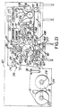
- Figure 13 is a schematic, elevation view of another embodiment of the machine of Figure 1 showing the overall apparatus which applies labels onto cylindrical articles such as crayons using a bottom feed conveying unit.
- Figure 14 is a schematic, isometric view of the label drum showing the label feed and cut mechanism, the heater assembly and bottom feed conveying unit.
- Figure 15 is a schematic, isometric view of a portion of the label drum showing the jet air nozzles and a portion of the cutter assembly.
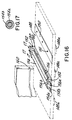
- Figure 16 is a schematic, isometric view of a portion of the bottom feed conveyor unit showing an article carrier formed of two rolls having outwardly extending pins which are received within the guide groove of the conveyor guide plate.
- Figure 17 is a sectional view of a pin taken along line 12-12 of Figure 9.
- Figure 18 is an exaggerated schematic, isometric view showing the leading edge of a label engaging the butt end of the crayon during label wrapping.
- Figure 19 is an isometric view of a novel crayon which has been wrapped by the method of the present invention and showing with hidden lines the leading edge of the label engaging the butt end of the crayon during label wrapping, as well as a covered registration mark, and unexposed printed indicia.
- Figure 20 is a schematic sectional view taken along line 20-20 of Figure 11 showing the double wrapped crayon.
- Figure 21 is a schematic, elevation view of another machine which applies labels onto cylindrical articles such as crayons using another type bottom feed conveying unit with a chain link conveyor.
- Figure 22 is a schematic, isometric view of the label drum showing the label feed and cut mechanism, the heater assembly and bottom feed conveying unit.
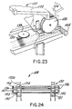
- Figure 23 is an isometric view of the vacuum wheel that feeds articles onto the conveyor.
- Figure 24 is a plan view in partial section showing the chain links and chain of the chain conveyor.
-
- Referring now to the drawings, there are illustrated three different embodiments of the present invention. The first embodiment is illustrated in Figures 1 through 12 and shows the machine with articles feed along a serpentine to the top part of the label drum. Figures 13 through 20 illustrate a second embodiment using a bottom feed unit and an article with a printed indicia and registration mark, Figures 19 and 20. Figures 21 through 24 illustrate a third embodiment where the bottom feed unit comprise a chain conveyor.
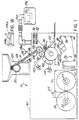
- Referring now to Figures 1 through 12 and the first embodiment, and more particularly to Figure 1, there is illustrated at 10 a schematic, overall illustration of the apparatus for applying a label onto a substantially cylindrical article such as tapered crayon wherein the label has seams aligned end-to-end on the article (Figure 12).
- The labels are thin layer, heat activated adhesive backed labels typically having at least one layer of paper with the adhesive applied evenly on one side. Throughout this description, the labels will be referred to by the letter "L." The
apparatus 10 may be used for applying a label to different tapered and nontapered articles and crayons requiring good end-to-end alignment of the label ends and high production speeds, which the apparatus and method of the present invention can provide. - The
apparatus 10 is suitable for high quality cylindrical labelling of different articles requiring the application of thin labels having a thickness typically less than about 0.127 mm (0.005 inches). Throughout the description and drawings, the cylindrical articles on which the labels are applied will be referred to as crayons and will be illustrated as such and given the reference letter "A." The illustrated crayons are typically formed from paraffin wax, and have a surface which is smooth and slick, making it resistant to water and some adhesives. In one desired application, the crayons are tapered, having one end about 8.18 mm (0.322 inches) diameter and the other end about 7.96 mm (0.314 inches) diameter, giving a taper of 0.178 mm (0.007 inches) from the wide "butt" end 14 of the crayon to the morenarrow end 16. (Figure 12) The crayons typically are about two to four inches long. - The label material applied to the illustrated crayons typically includes one layer of paper which is coated completely on one side with the heat activated adhesive. The paper can be a coarse grain paper which is inexpensive, but economical and practical considering the numerous crayons which are labelled. The heat activated adhesive layer is applied at about a one half to one mil coating thickness i.e., 12.7 to 25.4 µm (0.0005-0.001 inches). The adhesive is a low temperature heat activated adhesive which melts at a temperature range of about 60°C to 76.67°C (140 to 170 °F). Typical examples include a hot melt adhesive sold by Findley Adhesives, Inc.
- The label materials may be initially supplied as a
roll 18 of strip label material "S" which can be positioned on amandrel 22 of a feeder assembly indicated generally at 24. In the illustration, adouble mandrel roll 18. As oneroll 18 is used, theother roll 18 onmandrel 23 then is fed which maintains production. The strip "S" of label material is then fed through a feedroll assembly, indicated generally at 26, and to a cutting drum assembly, indicated generally at 28, which is operatively connected to the main drive motor andtransmission assembly 30 of a label transport drum indicated generally at 32. A registration andsensing system 34 sense label indicia to ensure proper cutting on the strip and ensure quality cutting of the labels. The registration can include a FIFE label edge registration control sensing system for printed label registration marker. Thefeedroll assembly 26 includes adancer roll assembly 36 and feedrolls 38 which move the strip S into the cuttingdrum assembly 28. - The
label transport drum 32 typically is supported on aframe assembly 40. The main drive motor andtransmission assembly 30 is supported by theframe 40 and rotates thelabel transport drum 32 as well as the cutting drum assembly by asuitable transmission 42. The cuttingdrum assembly 28 includes a cuttingroll 44 which is mounted to themachine frame 40 and positioned adjacent thelabel transport drum 32 at a lower portion thereof as shown in Figure 1. The cuttingroll 44 cuts the label strips into segments, i.e., labels, which are then fed onto consecutive label receiving positions, indicated at 46, of thelabel transport drum 32. (Figures 2, 3, and 5) Each label moves with therotating drum 32 into a heat tunnel, indicated at 48, where the adhesive is melted, and then into an article wrapping position, indicated at 50, where crayons are fed into tangential spinning engagement with the drum surface and into rotative engagement with a leading edge of the label "L" as the label moves into the article wrapping position so that the label wraps about the crayon and adheres thereto by means of the melted adhesive. The wrapped crayons are then discharged into adischarge chute 52. - Referring now to Figures 5-9, details of one embodiment of the
label transport drum 32 which can be used for the present invention are shown. As illustrated, a label drum, indicated at 60, is rotatably received over acentral hub 62. As shown in Figures 8 and 9, respective first and second radially extending, slottedvacuum manifolds manifolds hub 62. The vacuum and blow-off manifold at 64, 68 of Figure 8 are aligned circumferentially with each other, as are themanifolds gate manifolds 72b, and horizontal pressure manifolds 74a, andgate manifold 74b. An air pressure manifold 76 provides air against a leading edge of a label. As will be explained later, the second vacuum manifold extends afurther arc distance 79 than thefirst vacuum manifold 64. Thesecond vacuum manifold 66 retains the label on the drum surface if a label is not transferred onto an article. Once thedrum 60 continues its rotation, the blow-offmanifolds - Twelve evenly spaced label retaining insert plates, indicated at 78, are positioned on the surface of the label drum 60 (Figure 5). Each
insert plate 78 is rectangularly configured (Figure 6), and has a top surface that is configured substantially similar to the curvature of the drum surface.Screws 79 can secure theplates 78 to thedrum 60 and be used on everyplate 78 or every other plate, with every other unscrewed plate held by contiguous screwed plates. The under surface of each insert plate includes two plenums formed in the surface as shown in Figure 6. Afirst plenum 80 is formed on the undersurface and hasorifices 82 extending upward which communicate with a surface of the insert plate at that area where the leading edge of a label is to be positioned. The first plenum communicates with aport 84 in thedrum 60 which is positioned in circumferential alignment with thefirst vacuum manifold 64 and pressure manifold 76. - A
second plenum 86 is formed in the undersurface and hasorifices 88 extending upward therethrough to communicate with the surface of the insert plate at an area where the trailing edge and midportion of the label are positioned. Thesecond plenum 86 extends to aport 90 of the drum which is aligned circumferentially with the second vacuum manifold. - Each insert plate has a resilient pad 92 (Figures 2, 3, 5, and 7) placed over a substantial portion of the outer surface of the insert plate. The
orifices resilient pads 92 can be formed preferably from silicone or other similar material. Thepads 92 are contiguous with each other (Figures 3 and 5) and form a soft cushion on which the crayon rolls during wrapping and also form a smooth surface on which the label lies as the label moves from its initial position after cutting when it is first fed onto the drum surface and then moves into the article wrapping position 50 (Figure 2). Because thesilicone pads 92 act somewhat as a cushion, the crayon is deflected slightly into the cushion material by means of a pressure applicator, indicated at 96, so as to create a "footprint" in the soft cushion material. During crayon wrapping, the air is squeezed out between the crayon, label and pad surface, allowing better wrapping of the label about the crayon. Additionally, thesilicone pads 92 have greater friction between the crayons in the drum surfaces compared to steel or an aluminum surface so that less pressure need be applied by the pressure applicator. - The label retaining
insert plates 78 are limited in the illustrated embodiment to about a 11.43 cm (four and one-half inch) long label corresponding to about 11.43 cm (four and a half inch) wide insert plate. This has been found adequate for labelling most conventional crayons and other similar articles. - If longer labels are to be used for larger diameter articles, the
insert plates 78 can be made deeper and fewer in number, and thus longer along the arcuate portion of the top surface since the plate is longer and has a longer surface length on which the arc extends. However, the length is still limited because too deep aninsert plate 78 would interfere with the drum rotation about the hub. Alarger label drum 60 andhub 62 would have to be constructed. Further details of one example of the plate construction which could be used for the present invention can be found in US-A-5 344 519. - Once the label is received into the
label receiving position 46 on thelabel transport drum 32, vacuum holds the label onto the drum surface. The label transport drum rotates and moves the label into theheat tunnel 48 where the adhesive is heated to its melting point. At high operating speeds of about 500 to 600 articles per minute, the heat time is about 0.25 seconds. - As shown in Figure 4, the
heating tunnel 48 is defined by two opposingside bracket plates rear end plate top cover plate 110, and forms a heat tunnel positioned closely adjacent the surface of the label transport drum in a position before the article wrapping position as shown in Figure 2. Two high powered ceramic heater andblower assemblies top plate 110 at the front and rear portions. Both heaters produce a 538°C (1,000°F) blast of hot air. The firstrear heater 114 amplifies and heats the heat activated adhesive, and the secondfront heater 112 amplifies that heat to ensure that the hot melt adhesive melts adequately. The total time in which the label is contained within the heat tunnel is about 0.25 seconds, and corresponds to the high operating speeds of about 500 to 600 crayons per minute.Temperature sensors 115, preferably thermocouples, sense temperature in theheating tunnel 48. The heater andblower assemblies - The labels then continue into the
article wrapping position 50 where they engage the crayons which had been fed from ahopper 120 positioned at the top portion of the frame 40 (Figure 1). The crayons are retained in thehopper 120 and alarge gear 122 positioned at the lower discharge end of the hopper grabs a crayon at the eleven o'clock position and rotates it approximately ninety degrees to release it into aserpentine guide 124. The crayons continue downward through theserpentine guide 124, through agate 126, and into a double star wheel assembly indicated generally at 128. Thegate 126 between the serpentine transfer and first starwheel transfer roll is formed of latex rubber and soft enough so that it does not break the crayon it engages. Thegate 126 is normally biased in the closed position to prevent crayons from moving from the serpentine into the first starwheel transfer roll. A cylinder 126a actuates a piston 126b which raises thegate 126 to allow transfer of crayons from the serpentine 124 into the article receiving positions of the first starwheel. Theserpentine transfer 124 has an inner andouter rail inner rail 124a has a larger gap than the spacing of theouter rail 124b to accommodate the taper of the crayons A (Figure 1A). - The
double starwheel assembly 128 can be driven off the main drive system or a separate drive system and only for the starwheel assembly. In the illustrated embodiment, the starwheel assembly includes two starwheels.Article receiving slots 140 of thefirst star wheel 130 receive the crayons and transfer them into thesecond star wheel 132. The second star wheel has itsarticle receiving slots 142 formed such that the article, i.e., crayon, is slightly skewed about 0.5 degrees (angle X°) within the slots (Figure 10). This skewing can be accomplished by forming theslots 142 so that the crayon lies skewed therein, or by using inserts (not shown) which skew the crayon when positioned within theslot 142. As thesecond starwheel 132 rotates, the crayon moves downward into tangential spinning engagement with the drum surface and into engagement with the leading edge of a label at a skewed angle. - As shown in Figure 11, the crayons are conveyed onto the drum surface so that the wider "butt" end 14 of a crayon first engages the leading edge of a label before the opposing end. This effectively compensates for the taper of the crayon. At the same time, the leading
edge ports 84 in the drum are aligned with each insert plate and move over the pressure manifold 76. The jet of the leading edge of the label air from the manifold forces outward into engagement with the crayon. - During labeling, the
pressure applicator 96 imparts pressure to the crayon as it is wrapped. Thepressure applicator 96 includes a pressure plate 140 (Figure 2) that has a bottom surface engaging the crayon. Thepressure plate 140 is spring biased and supported by asecond support plate 142 fixed to the frame. Two respective pinion gears 144, 146 are positioned on thesupport plate 142 and mesh with each other. The pinion gears 144, 146 have threaded central shafts which engage the spacedpressure plate 140. A third gear (not shown) engages both pinion gears 144, 146, and is rotatable by a handle-shaft 148. As the handle-shaft 148 is turned, the third gear turns both gears so that they rotate in opposite directions, thus biasing the pressure plate against the side of the crayon. The amount of biasing force against the ends of the crayon determines how much the label can be aligned. Thepressure plate 140 can also be adjusted closer or farther from the label transport drum, which varies the pressure of wrapping the label on the article. Also, the crayon, once wrapped, is rolled further under pressure from the pressure plate which further cools the adhesive. - The label then wraps around the crayon and the adhesive cooled as it rolls and then moves into the
discharge chute 52 where it is then transferred into anarticle conveyor 150. Because the label engaged the "butt" end of the crayon first during wrapping, the taper is compensated for with the result that the label ends are aligned (Figure 12). Without skewing the article slightly, the label ends would not be aligned. - The
resilient pads 92 can become very hot during high speed operation, especially materials like silicone, and therefore a bank ofairjets 152 are positioned after thedischarge chute 52. These jets blow high speed air onto the silicone pads to cool same. A compressed air source andlines 154 provide the necessary air flow. Acontroller 156 is mounted as amovable swing arm 158 and controls machine operation. It can be easily swung out of the way. - In operation, a strip S is initially fed from a
feed roll 18 into thefeed roll assembly 26 andcutter drum assembly 28. The registration and sensor unit maintains proper registration of any label indicia with the cutting drum so that labels are properly cut at proper indicia and transferred exactly onto thelabel retaining positions 46 of thelabel transport drum 32. The drum rotates and moves labels through theheating tunnel 48, and then into thearticle wrapping position 50 where the leading edge of the label is forced upward into engagement with the skewed crayon, which has been fed from the second transfer roll. During wrapping, because the butt end of the crayon engages the leading edge of the label first, the label is wrapped and has end-to-end alignment of labels. The crayon then moves to a point where it is discharged into the chute and then transferred onto the conveyor. - Referring now to Figures 13 through 20, the second embodiment using a bottom feed unit is illustrated. Those structural elements in this second embodiment that are the same as the structural elements described in the first embodiment maintain the same reference number.
- Referring now to Figure 13, there is illustrated at 10 a schematic, overall illustration of the apparatus for applying a label onto a substantially cylindrical article such as tapered crayon wherein the label has seams aligned end-to-end on the article (Figure 19) by using a bottom feed conveying unit, illustrated generally at 12. The bottom feed conveying unit 12 of this embodiment of the present invention allows an operator to visually inspect articles during advancement into an article wrapping position.
- As in the previous embodiment of Figures 1 to 12, the machine of the present embodiment can work with the labels that are thin layer, heat activated adhesive backed labels typically having at least one layer of paper with the adhesive applied evenly on one side.
- The label material typically includes
printea indicia 17b which will be exposed after wrapping. Aregistration mark 17a can be included on the label material. Thisregistration mark 17a is sensed by registration sensors during film feed to ensure proper cutting of the label at the desired point. Typically, a crayon or other article is double wrapped (Figure 20a), and theregistration mark 17a covered. The printedindicia 17b, such as advertising and date codes, is exposed. - The label materials can be initially supplied as a
roll 18 of strip label material "S" which can be positioned on amandrel 22 of a feeder assembly indicated generally at 24. In the illustration, adouble mandrel roll 18. As oneroll 18 is used, theother roll 18 onmandrel 23 then is fed which maintains production. The strip "S" of label material is then fed through a feedroll assembly, indicated generally at 26, and to a cutting drum assembly, indicated generally at 28, which is operatively connected to the main drive motor and transmission assembly, indicated generally at 30, of a label drum indicated generally at 32. The cuttingdrum assembly 28 is located so that label material is fed and cut at the upper portion of thelabel drum 32. As thelabel drum 32 rotates, the label moves into anarticle wrapping position 33 located at the bottom portion of thelabel drum 32 where the articles are fed from the conveying unit 12. - A registration and
sensing unit 34 senses the label registration mark to ensure proper cutting of the strip on the desired cut line and ensure quality cutting of the labels. The cutpoint on the strip label is based on the registration point. The registration andsensing unit 34 can include a FIFE label edge registration control and an optical system for reading printed label registration markers. Thefeedroll assembly 26 includes adancer roll assembly 36 and feedrolls 38 which move the strip S into the cuttingdrum assembly 28. - The
label drum 32 typically is supported on aframe assembly 40. The main drive motor andtransmission assembly 30 is supported by theframe 40. The motor 41 rotates thelabel transport drum 32 by asuitable transmission 42. In the illustrated embodiment, the drive motor andtransmission 30 rotates the label drum in a clockwise direction. - The cutting
drum assembly 28 includes a cuttingroll 44 which is mounted to themachine frame 40 and positioned adjacent thelabel transport drum 32 at an upper portion thereof as shown in Figure 13. The cuttingroll 44 has acarbide knife 45 positioned thereon (Figure 14) which cuts the label strip into rectangular segments, i.e., labels "L", having leading and trailing edges, L1, L2. The leading edge L1 is transferred onto a label receiving position, indicated at 46, of thelabel transport drum 32. (Figures 14 and 15). The rest of the label then transfers to the label drum. Theroll 44 is rotated by atransmission 44a driven from thelabel drum 32. Thevacuum roll 44 can include vacuum draw which originates from avacuum hose 44b connected to an internal manifold and orifices of the vacuum roll. - The cutting
roll 44 can include a carbon steel substrate formed at the periphery of the roll and can be received over a central mandrel. The surface of the cuttingroll 44 may be enhanced. A nickel alloy coating is deposited onto the substrate and has micropores. A polytetrafluoroethylene (Teflon) polymer is integrated within the nickel alloy coating to form an integrated surface layer of about 25.4 to 50.8 µm (0.001 to 0.002 inches). The integrated surface layer has a surface hardness of about 65 to 68 Rockwell C scale. This surface has a coefficient of friction of about 0.03 (with 8 or lower RMS) so as to reduce the tendency of the label to build static and to aid in label transfer from the cutting drum onto the label drum. The cuttingroll 44 with this surface has an operating heat resistance range of about -101.11 to 510°C (-150 to +950°F). - The integrated surface can be formed by a coating process known commercially by the trade designation Magnaplate HMF and provided by General Magnaplate Corporation, 1331 Route 1, Linden, New Jersey 07036.
- Typically, when applying this surface enhancement, the substrate is pretreated and the nickel alloy is deposited on the substrate surface. Micropores are enlarged and the Teflon infused into the surface layer. The Teflon then is integrated within the layer.
- Besides the improvements of hardness and reduced coefficient of friction, the cutting roll has improved durability and anti-static electrical properties. The impregnated surface layer imparts dielectric resistance, a low dissipation factor, and very high surface resistivity. It is believed that the surface resistivity is about 60 micro ohm/cm over a wide range of frequencies. The impregnated surface layer also has corrosion resistance. Salt spray per ASTM B-117 exceeds 336 hours when the thickness is 25.4 µm (0.001 inches) or greater. The Equilibrium Wear Rate (EWR) using Taber Abrasion testing methods (CS-10 wheel): 0.2 - 0.4 mg per 1000 cycles.
- The cutting
roll 44 is positioned adjacent the drum and astationary knife 45a (Figure 13) engages the cuttingknife 45 to cut labels. Also, on-drum cutting can be used where theknife 45 engages a hardened surface of the label drum. An example of such cutting system is disclosed in US-A-5,350,482 to Westbury. The choice of cutting method depends on the labels used, the speed of operation, operator demands, as well as other factors related to the type of labeling operation. - A static eliminator 47 (Figure 13) can be positioned just after the cutting
drum assembly 28. The static eliminator 47 is beneficial because it reduces the heavy charge build-up. This can be critical because in very low humidity conditions the charge contained on the label causes the-labels to stick to the surface of the cuttingroll 44. The static eliminator 47 eliminates this charge which allows the label to transfer efficiently to thelabel drum 32. - Each label moves with the
rotating label drum 32 into a heating tunnel, indicated at 48, where the adhesive is melted, and then into thearticle wrapping position 33, located at the bottom portion of thelabel drum 32, where crayons or other articles are fed by the conveying unit 12 into tangential spinning engagement with the drum surface and into rotative engagement with a leading edge L1 of the label "L" as the label moves into thearticle wrapping position 33. The label wraps about the crayon twice and adheres thereto by means of the melted adhesive. The wrapped crayons are then discharged into a discharge chute or discharge conveyor assembly illustrated generally at 52 (Figure 13). - As noted in the description of the previous embodiment, Figures 1 through 12 illustrate
silicone pads 92. Because thesilicone pads 92 act somewhat as a cushion, the crayon is deflected slightly into the cushion material by means of upward pressure exerted by the conveying unit against the crayon andlabel drum 32, so as to create a "footprint" in the soft cushion material. During crayon wrapping, the air is squeezed out between the crayon, label and pad surface, allowing better wrapping of the label about the crayon. Additionally, thesilicon pads 92 have greater friction between the crayons in the drum surfaces compared to a steel or an aluminum surface so that less pressure need be applied by the upward biasing pressure of the conveyor. - The
heaters shafts - As shown in Figure 13, the crayons, are retained in a hopper, indicated at 120, spaced from the label drum. The
hopper 120 includes abasin 122 with an inclined floor in which the crayons are contained. The lower portion of the basin has a throughchannel 124 which feeds into alarge vacuum wheel 126 positioned at'the lower discharge end of the basin and grabs a crayon at the 12:00 position, holds the crayon with its formed slots by vacuum and rotates it approximately 180 degrees to release it onto a carrier, indicated generally at 130, of the conveyor. Thevacuum wheel 126 includes a source of vacuum (not shown) for retaining the crayons within the slots formed in the wheel. - A
sensor 132 indicates when acarrier 130 is approaching the drop off point of the vacuum wheel and signals to acontroller 140 the sensed location of the carrier. Vacuum wheel rotation is then timed so that the crayon is dropped onto thecarrier 130 when the carrier is opposite the drop off point defined by the lower-most point of thevacuum wheel 126. Vacuum wheel rotation can be controlled by adrive mechanism 134 which operatively connects to thesensor 132 viacircuitry 136 and thecontroller 140. - As shown in Figure 13, the conveyor 12 includes a
distal drive wheel 144 mounted to theframe 40 and a firstproximal drive wheel 146 adjacent the article wrapping position. An endless, looped and luggedconveyor belt 148 is coupled about the two drive wheels, which also are geared to receive thelugs 148a of the belt (Figure 14). Theproximal drive wheel 146 is mounted on asupport shaft 146a rotatably mounted between shaft supports 147 fixed to theframe 40. Thedistal drive wheel 144 includes a gear linkage (indicated generally at 149) which is geared to the label drum drive with a clutch mechanism for overload protection. Alternatively, a drive motor could drive thedistal drive wheel 144 to move theconveyor 148. Thecontroller 140 could operatively connect to the motor to allow an operator to control the conveyor. -
Carriers 130 are spaced two inches apart on thebelt 148. (For purposes of illustration, Figure 14 illustrates only one carrier and Figure 13 has only part of thebelt showing carriers 130.) Each carrier is about four inches wide corresponding to the width of theconveyor belt 148. The carriers are supported and secured to thebelt 148 by threaded fasteners (not shown) extending through the bottom portion of the carrier and extending intofastening plates 150 secured onto thebelt 148. Theplates 150 include threadedholes 151 which receives bolts (not shown) for holding thecarriers 130. Theplates 150 can be configured to allow different configured carriers to be secured to the belt to accommodate different articles (Figure 16). - In Figure 16, each
carrier 130 includes roll supports 152 which support tworolls rollers - Each roll has outwardly extending
shafts brass bearing member shaft members members 154a, b, 156a, b enter agroove 160 of respective parallel spacedguide plates 162 at thearticle wrapping position 33. As shown in Figure 13, thecarriers 130 follow the arcuate configuredgroove 160 so that thecarriers 130 move around the lower portion of thelabel drum 32. This allows a crayon within thecarrier 130 to engage the surface of the label drum throughout its lower periphery. Arigid support surface 166 is located underneath theconveyor belt 148 proximal to the article wrapping position at a point where the conveyor approaches the label drum so that thecarriers 130 will not exert downward pressure on the conveyor belt and cause slack, which could create error during labeling. - The
guide plates 162 are each mounted on twoThompson Bearings 167 which allows the guide plates to be raised and lowered independently of each other. TheThompson Bearings 167 rest on a horizontally configuredsupport plate 168. The Thompson Bearings include ashaft 170 received within a bearinghousing 171 as is conventional. Twojack screws 172 are positioned on either side of thearticle wrapping position 33 and rest on thesupport plate 168. The jack screws 172 raise theguide plates 162 toward the label drum and move thecarriers 130 closer toward the surface of the label drum, thus engaging the crayons carried thereon into engagement with the surface of the label drum. The amount that thejack screws 172 are turned corresponds to the desired pressure on the crayon during labeling. Also, thejack screws 172 can be turned to vary the camber of the article relative to the label to aid in ensuring end-to-end alignment during labeling. The jack screws 172 can be hydraulically operated coupled to a motor and drive mechanism (not shown in detail) so that an operator can readily control the camber and pressure of the crayon during labeling via thecontroller 140. - As illustrated in Figures 13 and 14, the
support plate 168 is supported on a mountingplate 176 at each corner byjack screws 177. Thesupport plate 168 is gimbled at the center so that the camber of thesupport plate 168 can be varied. The mountingplate 176 is closely spaced to thesupport plate 168. Small, finite adjustments in the camber of thesupport plate 168 relative to the mountingplate 176 are made by individually turning desired jack screws 177. - As the
label drum 32 continues its clockwise rotation, the labels then continue into thearticle wrapping position 33 where they engage the crayons advancing along the article conveyor 12. - As shown in Figure 18, the crayons are conveyed onto the drum surface so that the crayon engages the leading edge of a label. At the same time, the leading
edge ports 84 in the drum that are aligned with each insert plate move over the pressure manifold 76. The jet of air from the manifold forces outward the leading edge of the label into engagement with the crayon. - The label then wraps around the crayon twice and the adhesive is cooled as it rolls. During labeling side-to-side pressure on the crayon is varied to compensate for crayon taper. The
original registration mark 17a is covered and printed indicia present on the label exposed. The crayon then moves into the discharge chute orconveyor 52. - The resilient silicon or similarly formed
pads 78 can become very hot during high speed operation, and therefore a bank of airjets 180 (Figure 15) are positioned on the label drum side opposing the heater assembly. Thesejets 180 blow high speed air onto the silicone pads to cool same. A compressed air source andlines 182 provide the necessary air flow. - In operation, a strip S is initially fed from a
feed roll 18 into thefeed roll assembly 26 andcutter drum assembly 28. The registration and sensor unit maintains proper registration of any label points with the cutting drum so that labels are cut at proper points and transferred exactly onto thelabel retaining positions 46 of thelabel transport drum 32. The drum rotates and moves labels through theheating tunnel 48, and then into thearticle wrapping position 33 where the leading edge of the label is forced upward into engagement with the crayon, which has been fed into engagement with the drum by the conveyor. During wrapping, the applied differential pressure causes the label to skew during labeling with the result that the label is wrapped and has end-to-end alignment. The crayon then moves to a point where it is discharged into the discharge conveyor. - Referring now to Figures 21 through 24, a labeling machine is illustrated, which includes a bottom feed unit in the form of a chain conveyor.
- Referring now to Figure 21, there is illustrated at 10 a schematic, overall illustration of the apparatus for applying a label onto a substantially cylindrical article such as a tapered crayon wherein the label has seams aligned end-to-end on the article (Figure 19) by using a bottom feed conveying unit, in the form of a chain conveyor, illustrated generally at 12. The bottom feed conveying unit 12 allows an operator to visually inspect articles during advancement into an article wrapping position.
- As shown in Figure 21, the crayons, are retained in a hopper, indicated at 120, spaced from the label drum. The
hopper 120 includes abasin 122 with an inclined floor in which the crayons are contained. The lower portion of the basin has a throughchannel 124 which feeds into alarge vacuum wheel 126 positioned at the lower discharge end of the basin and grabs a crayon at the 12:00 position, holds the crayon with its formed slots by vacuum and rotates it approximately 180 degrees to release it to rest betweensupport rods 130 of the conveyor. Thevacuum wheel 126 includes a source of vacuum (not shown) for retaining the crayons within the slots formed in the wheel. - A sensor (not shown) could be used to indicate when a
rod 130 is approaching the drop off point of thevacuum wheel 126 and signal to acontroller 140 the sensed location of the carrier. Vacuum wheel rotation is then timed so that the crayon is dropped onto thesupport rods 130 when the two support rods are opposite the drop off point defined by the lower-most point of thevacuum wheel 126. Vacuum wheel rotation can be controlled by adrive mechanism 134 which operatively connects to thesensor 132 viacircuitry 136 and the controller. Once the crayon or other article has dropped onto the conveyor, each crayon resting on twosupport rods 130 is aligned by engaging aregistration wheel 139. - As shown in Figure 21, the chain conveyor 12 includes a
distal drive sprocket 144 mounted to theframe 40 and a firstproximal drive sprocket 146 adjacent the article wrapping position. Anendless conveyor chain 148 is coupled about the two drive sprockets. (Figure 22). Theproximal drive sprocket 146 is mounted on asupport shaft 146a rotatably mounted between shaft supports 147 fixed to theframe 40. Thedistal drive sprocket 144 can include a gear linkage (indicated generally at 149) which is geared to the label drum drive with a clutch mechanism for overload protection. Alternatively, a drive motor could drive thedistal drive sprocket 144 to move theconveyor 148. Thecontroller 140 could operatively connect co the motor to allow an operator to control the conveyor. - As illustrated in Figures 23 and 24, the chain conveyor 12 is formed from an
endless conveyor chain 148 that includes two chain loops indicated generally at 150a, 150b (a portion shown in Figure 24), each formed from a plurality of interconnected chain links 151. As is typical, eachchain link 151 includes aguide hole 152. Thesupport rods 130 includeshafts 154 that enter through the guide holes 152 and "lock" the chain loops together. - Each
support rod 130 has outwardly extendingshafts 154 and abrass bearing member 156, rotatably positioned over eachshaft 154, (Figure 24). Thebrass members 156, are freely rotatable thereon, and could be retained by a washer andlocknut 157 or an E-clip such as known to those skilled in the art. Typically, thesupport rods 130 are spaced such that the pitch between the crayons resting on therods 130 is about 25.4 mm (one inch). - The shaft and
members groove 160 of respective parallel spacedguide plates 162 at thearticle wrapping position 33. As shown in Figure 21, the conveyor follows the arcuate configuredgroove 160 so that any crayon carried thereon moves around the lower portion of thelabel drum 32. This allows a crayon held on therods 130 to engage the surface of the label drum throughout its lower periphery. Arigid support surface 166 can be located underneath the conveyor proximal to the article wrapping position at a point where the conveyor approaches the label drum so that theconveyor chain 148 will not exert downward pressure and cause slack, which could create error during labeling. - In operation, a strip S is initially fed from a
feed roll 18 into thefeed roll assembly 26 andcutter drum assembly 28. The registration and sensor unit maintains proper registration of any label points with the cutting drum so that labels are cut at proper points and transferred exactly onto thelabel retaining positions 46 of thelabel transport drum 32. The drum rotates and moves labels through theheating tunnel 48, and then into thearticle wrapping position 33 where the leading edge of the label is forced upward into engagement with the crayon, which has been fed into engagement with the drum by the conveyor. During wrapping, the applied differential pressure causes the label to skew during labeling with the result that the label is wrapped and has end-to-end alignment. The crayon then moves to a point where it is discharged onto adischarge conveyor chain 190 or other similar discharge device known to those skilled in the art. - It should be understood that the foregoing description of the invention is intended merely to be a illustrative thereof, and that other embodiments, modifications and equivalents may be apparent to those skilled in the art without departing from its scope as recited in the claims.
Claims (9)
- A method for applying a label (L) onto a substantially cylindrical article (A) comprising the steps of:feeding a thin layer, heat activated adhesive backed label onto a label receiving position of a rotating label transport drum (32);heating the adhesive as the drum (32) rotates so that the adhesive obtains a sufficient temperature to melt; andtransferring the label (L) onto a cylindrical article (A) at an article wrapping position, characterized in that said rotating label transport drum (32) has label receiving positions formed of a substantially smooth, resilient material such as silicon, and by the step ofblowing a jet of air onto the resilient surface for cooling the surface during subsequent label applying and ensuring rapid cooling of melted adhesive during labeling.
- A method according to claim 1, including the step of moving the label (L) past a heat source (48) to initially heat the adhesive, and then ensuring that the heat activated adhesive has obtained a sufficient temperature to melt so that it adheres to the cylindrical article (A).
- A method according to claim 1, wherein the articles (A) are crayons and the heat activated adhesive layer positioned on the back of the paper is about 12.7 to 25.4 µm (0.0005-0.001 inches) thick.
- A method according to claim 1, wherein the heat activated adhesive has a melting range of about 60°C to 76,67°C (140 to about 170 degrees Fahrenheit).
- An apparatus (10) for applying a label (L) onto a substantially cylindrical article (A) comprisinga label transport drum (32);means for rotating said drum (32);means (26) for feeding a thin layer, heat activated adhesive backed label (L) onto a label receiving position of said drum (32);means (48) for heating the adhesive as the drum (32) rotates so that the adhesive obtains a sufficient temperature to melt; andmeans for conveying substantially cylindrical articles (A) into tangential spinning engagement with the drum (32) and into rotative engagement with the leading edge of the label (L) as the label (L) moves into an article wrapping position so that the label (L) wraps about the article (A) and adheres thereto, characterized in that said drum (32) has label receiving positions formed of a substantially smooth, resilient surface such as silicon, and bymeans for blowing a jet of air onto the resilient drum surface for cooling the surface during subsequent label applying and ensuring rapid cooling of melted adhesive during labeling.
- An apparatus (10) according to claim 5, wherein said means for blowing a jet of air comprises a bank of jet nozzles positioned adjacent the label transport drum (32).
- An apparatus (10) according to claim 5, including a heat source to initially heat the adhesive, and a heat source for ensuring that the heat activated adhesive has obtained a sufficient temperature to melt so that it adheres to the cylindrical article (A).
- An apparatus (10) according to claim 5 being adapted for applying said label (L) onto crayons, wherein the heat activated adhesive layer positioned on the back of the paper is about 12.7 to 25.4 µm (0.0005-0.001 inches) thick.
- An apparatus (10) according to claim 5 being adapted for applying a label (L) with a heat activated adhesive having a melting range of about 60°C to 76.67°C (140 to about 170 degrees Fahrenheit).
Applications Claiming Priority (7)
| Application Number | Priority Date | Filing Date | Title |
|---|---|---|---|
| US34278094A | 1994-11-21 | 1994-11-21 | |
| US342780 | 1994-11-21 | ||
| US427289 | 1995-04-21 | ||
| US08/427,289 US5749990A (en) | 1994-11-21 | 1995-04-21 | Method and apparatus for applying labels to articles using bottom feed conveying unit |
| US551986 | 1995-11-02 | ||
| US08/551,986 US5779835A (en) | 1994-11-21 | 1995-11-02 | Method and apparatus for applying labels to articles using bottom feed chain conveyor |
| EP95944303A EP0792238B1 (en) | 1994-11-21 | 1995-11-20 | Labelled elongated article and labelled crayon |
Related Parent Applications (1)
| Application Number | Title | Priority Date | Filing Date |
|---|---|---|---|
| EP95944303A Division EP0792238B1 (en) | 1994-11-21 | 1995-11-20 | Labelled elongated article and labelled crayon |
Publications (2)
| Publication Number | Publication Date |
|---|---|
| EP0884245A1 EP0884245A1 (en) | 1998-12-16 |
| EP0884245B1 true EP0884245B1 (en) | 2002-03-06 |
Family
ID=27407539
Family Applications (3)
| Application Number | Title | Priority Date | Filing Date |
|---|---|---|---|
| EP95944303A Expired - Lifetime EP0792238B1 (en) | 1994-11-21 | 1995-11-20 | Labelled elongated article and labelled crayon |
| EP98113680A Expired - Lifetime EP0884244B1 (en) | 1994-11-21 | 1995-11-20 | Method and apparatus for wrapping cylindrical articles with hot melt adhesive backed label |
| EP98113681A Expired - Lifetime EP0884245B1 (en) | 1994-11-21 | 1995-11-20 | Method and apparatus for wrapping cylindrical articles with hot melt adhesive backed label |
Family Applications Before (2)
| Application Number | Title | Priority Date | Filing Date |
|---|---|---|---|
| EP95944303A Expired - Lifetime EP0792238B1 (en) | 1994-11-21 | 1995-11-20 | Labelled elongated article and labelled crayon |
| EP98113680A Expired - Lifetime EP0884244B1 (en) | 1994-11-21 | 1995-11-20 | Method and apparatus for wrapping cylindrical articles with hot melt adhesive backed label |
Country Status (10)
| Country | Link |
|---|---|
| US (1) | US5779835A (en) |
| EP (3) | EP0792238B1 (en) |
| AT (3) | ATE214018T1 (en) |
| AU (1) | AU4638796A (en) |
| DE (3) | DE69525776T2 (en) |
| DK (3) | DK0884245T3 (en) |
| ES (3) | ES2175565T3 (en) |
| GR (1) | GR3034382T3 (en) |
| PT (3) | PT792238E (en) |
| WO (1) | WO1996015943A2 (en) |
Families Citing this family (13)
| Publication number | Priority date | Publication date | Assignee | Title |
|---|---|---|---|---|
| US6450230B1 (en) * | 1999-06-24 | 2002-09-17 | S-Con, Inc. | Labeling apparatus and methods thereof |
| ITPD20020057U1 (en) * | 2002-07-30 | 2004-01-30 | Acqua Minerale S Benedetto S P | IMPROVED SHOE FOR TRANSFER ROLLERS LABELS IN PLANTS LABELING OF CONTAINERS AT LEAST FOR CYLINDRICAL SHAPED AREAS |
| DE10243701A1 (en) * | 2002-09-20 | 2004-03-25 | Khs Maschinen- Und Anlagenbau Ag | Roll-feed labeling machines for processing an endless label tape coated with thermally activated glue |
| US7150745B2 (en) * | 2004-01-09 | 2006-12-19 | Barrx Medical, Inc. | Devices and methods for treatment of luminal tissue |
| DE102006013844A1 (en) * | 2006-03-25 | 2007-10-11 | Khs Ag | Vacuum drum and labeling machine with such a drum for all-round labeling of bottles or similar containers |
| DE102006051898A1 (en) * | 2006-10-31 | 2008-05-08 | Khs Ag | vacuum drum |
| NL1035494C2 (en) * | 2008-05-29 | 2009-12-01 | Fuji Seal Europe Bv | Device for manufacturing sleeve-like foil envelopes from a flat strip of foil material. |
| EP2440466A4 (en) | 2009-06-09 | 2015-12-09 | Graphic Packaging Int Inc | Article selection and placement assembly and method |
| US8828170B2 (en) | 2010-03-04 | 2014-09-09 | Pactiv LLC | Apparatus and method for manufacturing reinforced containers |
| EP2759484A1 (en) * | 2013-01-25 | 2014-07-30 | SIDEL S.p.A. con Socio Unico | Vacuum drum, particularly for a roll-fed labelling machine, and vacuum drum pad |
| CN109132071A (en) * | 2018-07-31 | 2019-01-04 | 俞斌 | A kind of automatic labeling machine |
| WO2021242969A1 (en) | 2020-05-29 | 2021-12-02 | Graphic Packaging International, Llc | Method and system for changing article pitch |
| EP4263366A1 (en) * | 2020-12-15 | 2023-10-25 | P.E. Labellers S.p.A. | Labeling machine |
Family Cites Families (90)
| Publication number | Priority date | Publication date | Assignee | Title |
|---|---|---|---|---|
| DE208261C (en) * | ||||
| US2668632A (en) * | 1949-11-08 | 1954-02-09 | Beech Nut Packing Co | Labeling machine |
| US2613007A (en) * | 1950-01-18 | 1952-10-07 | New Jersey Machine Corp | Method of and apparatus for activating labels |
| US2703660A (en) * | 1954-01-19 | 1955-03-08 | New Jersey Machine Corp | Labeling machine |
| FR1229536A (en) * | 1958-07-11 | 1960-09-07 | Johann Weiss Maschinenfabrik & | Device for labeling bottles or similar objects |
| DE1103230B (en) * | 1959-01-07 | 1961-03-23 | Strunek & Co Maschinenfabrik H | Device for applying labels provided with a thermoplastic adhesive layer to cylindrical or similarly shaped objects |
| US3159521A (en) * | 1960-12-12 | 1964-12-01 | Strunck & Co H | Apparatus to sever, print and apply labels to containers |
| US3235433A (en) * | 1962-05-15 | 1966-02-15 | Reynolds Metals Co | Method and apparatus for applying labels to containers |
| US3577293A (en) * | 1962-09-19 | 1971-05-04 | Continental Can Co | Method of labelling cylindrical objects |
| GB995524A (en) * | 1963-04-05 | 1965-06-16 | Ncr Co | Adhesive applicator |
| GB1106653A (en) * | 1964-07-23 | 1968-03-20 | Cow & Gate Ltd | Method and apparatus for applying pressure-sensitive adhesive tape to cylindrical articles |
| GB1129022A (en) * | 1966-08-10 | 1968-10-02 | Andersen & Bruun Ltd | Improvements relating to labelling machines |
| US3565724A (en) * | 1967-07-31 | 1971-02-23 | Nishimura Seisakusho Co | Automatic labelling machine |
| NL6916506A (en) * | 1968-11-16 | 1970-05-20 | ||
| DE1924131A1 (en) * | 1969-05-12 | 1970-11-19 | Strunck & Co Maschf H | Device for labeling objects |
| US3604584A (en) * | 1969-06-10 | 1971-09-14 | Anchor Hocking Corp | Method for protecting glassware and the article produced thereby |
| US3765991A (en) * | 1970-01-23 | 1973-10-16 | B & J Mfg Co | Labeling apparatus |
| US3834963A (en) * | 1970-01-23 | 1974-09-10 | B & J Mfg Co | Method for applying labels to containers |
| US3957570A (en) * | 1971-10-13 | 1976-05-18 | F. L. Smithe Machine Company, Inc. | Machinery for patching envelopes and the like |
| US4108710A (en) * | 1972-02-14 | 1978-08-22 | B & H Manufacturing Company, Inc. | Apparatus for applying labels to containers |
| US3878960A (en) * | 1972-06-12 | 1975-04-22 | Platmanufaktur Ab | Glass container with a shrunk-on plastic protective cover |
| CA1012906A (en) * | 1973-06-26 | 1977-06-28 | Hubert J. Germiat | Film labeled metal container and method therefor |
| US4108709A (en) * | 1976-06-14 | 1978-08-22 | B & H Manufacturing Company, Inc. | Label applying machine |
| US4108711A (en) * | 1977-02-23 | 1978-08-22 | B & H Manufacturing Company, Inc. | Label feed |
| US4500386A (en) * | 1977-03-31 | 1985-02-19 | B & H Manufacturing Company, Inc. | Container feed for labeling machine |
| US4124433A (en) * | 1977-06-06 | 1978-11-07 | American Can Company | Apparatus for applying a decoration to a cylindrical body |
| GB2029280A (en) * | 1978-05-31 | 1980-03-19 | Britannia Refining Co Ltd | Glue dispensing apparatus for a labelling machine. |
| FR2427987A1 (en) * | 1978-06-06 | 1980-01-04 | Dupuy Eng Sa | Appts. for cutting and dispensing flexible adhesive tape - opt. incorporating rolls with flexible polyurethane foam or PTFE surfaces |
| US4216044A (en) * | 1978-07-07 | 1980-08-05 | American Can Company | Method for applying a decoration to a cylindrical body |
| US4242167A (en) * | 1978-10-26 | 1980-12-30 | B & H Manufacturing Company, Inc. | Labeling machine |
| CA1155806A (en) * | 1978-12-05 | 1983-10-25 | Martin Malthouse | Labelling equipment |
| EP0018457B1 (en) * | 1978-12-05 | 1984-05-16 | Associpak International Inc. | Labelling equipment |
| US4207832A (en) * | 1978-12-18 | 1980-06-17 | Long-Lok Fasteners Corporation | Notched applicator wheel |
| US4208236A (en) * | 1978-12-20 | 1980-06-17 | Valco Cincinnati, Inc. | Glue application apparatus for use with can labeling machines and the like |
| WO1980002131A1 (en) * | 1979-04-05 | 1980-10-16 | Fukushima Printing Ind | Apparatus for adhering labels |
| US4336095A (en) * | 1979-11-13 | 1982-06-22 | B & H Manufacturing Company, Inc. | Machine for labeling bodies and shoulders of containers |
| JPS6042095B2 (en) * | 1980-01-16 | 1985-09-20 | 光洋自動機株式会社 | Adhesive supply device |
| US4332635A (en) * | 1980-07-03 | 1982-06-01 | American Can Company | Cup labeling method and apparatus |
| GB2088819B (en) * | 1980-10-24 | 1984-05-16 | Sun Chemical Corp | Labelling machine |
| US4366016A (en) * | 1981-06-25 | 1982-12-28 | Owens-Illinois, Inc. | Method and apparatus for producing a plastic sleeve |
| US4425866A (en) * | 1981-09-28 | 1984-01-17 | B & H Manufacturing Company, Inc. | Machine and method for coating plastic containers |
| US4447280A (en) * | 1981-10-22 | 1984-05-08 | Malthouse Martin D | Labelling machine |
| IT1168332B (en) * | 1981-12-03 | 1987-05-20 | Lucchese Finanz | Feed for gluing outer end of stick of wound paper |
| US4844957A (en) * | 1982-05-27 | 1989-07-04 | B & H Manufacturing Company, Inc. | System for applying heat shrink film to containers and other articles and heat shrinking the same |
| US4977002A (en) * | 1982-05-27 | 1990-12-11 | B & H Manufacturing Company, Inc. | System for applying heat shrink film to containers and other articles and heat shrinking the same |
| US4704173A (en) * | 1982-05-27 | 1987-11-03 | Wolfgang Hoffman | System for applying heat shrink film to containers and other articles and heat shrinking the same |
| US4545832A (en) * | 1982-05-27 | 1985-10-08 | B & H Manufacturing Company, Inc. | Machine and method for applying heat shrink labels |
| US4416714A (en) * | 1982-05-27 | 1983-11-22 | B & H Manufacturing Company, Inc. | Labeling machine for heat shrink labels |
| US4406721A (en) * | 1982-05-27 | 1983-09-27 | B & H Manufacturing Company, Inc. | System and apparatus for applying heat shrink film to containers and other articles and heat shrinking the same |
| US4443285A (en) * | 1982-06-08 | 1984-04-17 | New Way Packaging Machinery, Inc. | Tapered article labelling machine and method |
| US4519868A (en) * | 1982-11-12 | 1985-05-28 | Wolfgang Hoffmann | Computer controlled labelling machine |
| US4552608A (en) * | 1983-09-16 | 1985-11-12 | B & H Manufacturing Company | System for computer controlled labeling machine |
| JPS59163134A (en) * | 1983-02-24 | 1984-09-14 | 渋谷工業 株式会社 | Intermittent feeder for roll label |
| US4496409A (en) * | 1983-07-05 | 1985-01-29 | Owens-Illinois, Inc. | Methods and machines for placing and heating oriented plastic heat-shrinkable sleeves on containers |
| US4604154A (en) * | 1983-11-28 | 1986-08-05 | Owens-Illinois, Inc. | Apparatus and method for guiding plastic labels to a label-wrapping station |
| US4671836A (en) * | 1983-11-28 | 1987-06-09 | Owens-Illinois, Inc. | Container with solid plastic label and method of applying the label |
| US4574020A (en) * | 1983-11-28 | 1986-03-04 | Owens-Illinois, Inc. | Apparatus and method for wrapping a plastic label around a container |
| US4544431A (en) * | 1985-02-06 | 1985-10-01 | Stackpole Limited | Roll fed labelling machine |
| US4694633A (en) * | 1985-05-21 | 1987-09-22 | Fuji Seal Industry Co., Ltd. | Film wrapping machine |
| EP0208261A2 (en) * | 1985-07-12 | 1987-01-14 | CERAMI COLOR Gesellschaft für Hartfaserbeschichtung m.b.H. | Method and device for coating flat objects |
| US4632721A (en) * | 1985-10-07 | 1986-12-30 | Kris-Tech Corporation | Apparatus for applying labels to containers |
| US4735668A (en) * | 1985-10-07 | 1988-04-05 | Shibuya America Corporation | Method of adhering labels to containers |
| US4686931A (en) * | 1985-11-04 | 1987-08-18 | Owens-Illinois, Inc. | Apparatus for applying a solvent to plastic labels |
| US4662925A (en) * | 1985-12-09 | 1987-05-05 | Ppg Industries, Inc. | Horizontal press bending of heat softened glass sheets |
| US4636278A (en) * | 1985-12-20 | 1987-01-13 | Labelette Company | Apparatus for labeling nesting type buckets |
| US4724029A (en) * | 1986-02-24 | 1988-02-09 | Owens-Illinois, Inc. | Method and apparatus for applying a flexible plastic label to a round container |
| US4729811A (en) * | 1986-04-28 | 1988-03-08 | Owens-Illinois Glass Container Inc. | Infeed guide and roll-on belt for bottle labeling machine |
| US4724037A (en) * | 1986-04-28 | 1988-02-09 | Owens-Illinois Glass Container Inc. | Micro-adjustable gravure roll |
| US4726872A (en) * | 1986-04-28 | 1988-02-23 | Owens-Illinois Glass Container Inc. | Primary-secondary pad system |
| US4693210A (en) * | 1986-04-28 | 1987-09-15 | Owens-Illinois, Inc. | Quick change fountain |
| US4844760A (en) * | 1986-09-23 | 1989-07-04 | Trine Manufacturing Co., Inc. | Apparatus and method for applying |
| US4761200A (en) * | 1987-02-20 | 1988-08-02 | Owens-Illinois Plastic Products Inc. | Apparatus for applying a flexible plastic label to a round container |
| US4772354A (en) * | 1987-03-19 | 1988-09-20 | Owens-Illinois Glass Container Inc. | Heated solvent applicating gravure roll |
| US4781785A (en) * | 1987-11-13 | 1988-11-01 | Owens-Illinois Plastic Products Inc. | Apparatus for applying flexible plastic labels to round containers |
| US4832774A (en) * | 1988-05-06 | 1989-05-23 | Owens-Illinois Glass Container Inc. | Method and apparatus for applying wrap-around labels to containers |
| US4931122A (en) * | 1988-05-31 | 1990-06-05 | B & H Manufacturing Company, Inc. | Straight through labelling machine |
| US4923557A (en) * | 1988-08-01 | 1990-05-08 | Trine Manufacturing Co., Inc. | Apparatus and method for applying a heat shrink film to a container |
| DE3927296A1 (en) * | 1988-11-03 | 1990-05-10 | Eti Tec Maschinenbau | LABELING MACHINE FOR LABELING CONTAINERS WITH LABELS REMOVED BY THE CONTAINERS FROM A STACK OF LABELS |
| US4984413A (en) * | 1989-04-24 | 1991-01-15 | K. C. Technical Services, Inc. | Machine and method for overwrapping cylindrical articles |
| US5045140A (en) * | 1989-04-28 | 1991-09-03 | Cms Gilbreth Packaging Systems, Inc. | Ultra high speed labeling apparatus and method |
| US5037499A (en) * | 1989-11-29 | 1991-08-06 | B & H Manufacturing Company, Inc. | Labeling machine combining a turret and a vacuum drum-roll on pad |
| US5091239A (en) * | 1990-03-07 | 1992-02-25 | Cms Gilbreth Packaging Systems, Inc. | Methods and adhesives for bonding polyolefin film |
| US5091040A (en) * | 1990-05-03 | 1992-02-25 | B & H Manufacturing Co., Inc. | Turret type labeling machine with contoured vacuum drum |
| DE9016591U1 (en) * | 1990-12-06 | 1991-02-21 | Krones Ag Hermann Kronseder Maschinenfabrik, 8402 Neutraubling, De | |
| US5401353A (en) * | 1992-06-30 | 1995-03-28 | Cms Gilbreth Packaging Systems | Apparatus and method for applying labels onto small cylindrical articles using static wipers |
| US5405487A (en) * | 1992-06-30 | 1995-04-11 | Cms Gilbreth Packaging Systems, Inc. | Apparatus and method for applying labels onto small cylindrical articles and web and adhesive delivery mechanism |
| US5399216A (en) * | 1992-06-30 | 1995-03-21 | Cms Gilbreth Packaging Systems | Apparatus and method for applying labels onto small cylindrical articles using pressure applicator to prevent label mismatching |
| US5344519A (en) * | 1992-06-30 | 1994-09-06 | Cms Gilbreth Packaging Systems | Apparatus for applying labels onto small cylindrical articles having improved vacuum and air pressure porting for label transport drum |
| US5350482A (en) * | 1992-06-30 | 1994-09-27 | Cms Gilbreth Packaging Systems | Apparatus and method for applying labels onto small cylindrical articles |
| US5458728A (en) * | 1994-06-27 | 1995-10-17 | Galchefski; John | Apparatus and method for applying labels onto small cylindrical articles with improved seam formation by retarded article rotation |
-
1995
- 1995-11-02 US US08/551,986 patent/US5779835A/en not_active Expired - Lifetime
- 1995-11-20 AT AT98113681T patent/ATE214018T1/en not_active IP Right Cessation
- 1995-11-20 ES ES98113680T patent/ES2175565T3/en not_active Expired - Lifetime
- 1995-11-20 AU AU46387/96A patent/AU4638796A/en not_active Abandoned
- 1995-11-20 WO PCT/US1995/015379 patent/WO1996015943A2/en active IP Right Grant
- 1995-11-20 DE DE69525776T patent/DE69525776T2/en not_active Expired - Fee Related
- 1995-11-20 PT PT95944303T patent/PT792238E/en unknown
- 1995-11-20 DK DK98113681T patent/DK0884245T3/en active
- 1995-11-20 PT PT98113681T patent/PT884245E/en unknown
- 1995-11-20 DE DE69517999T patent/DE69517999T2/en not_active Expired - Fee Related
- 1995-11-20 ES ES95944303T patent/ES2148592T3/en not_active Expired - Lifetime
- 1995-11-20 DK DK98113680T patent/DK0884244T3/en active
- 1995-11-20 AT AT95944303T patent/ATE194567T1/en not_active IP Right Cessation
- 1995-11-20 DE DE69525775T patent/DE69525775T2/en not_active Expired - Fee Related
- 1995-11-20 EP EP95944303A patent/EP0792238B1/en not_active Expired - Lifetime
- 1995-11-20 EP EP98113680A patent/EP0884244B1/en not_active Expired - Lifetime
- 1995-11-20 DK DK95944303T patent/DK0792238T3/en active
- 1995-11-20 ES ES98113681T patent/ES2175566T3/en not_active Expired - Lifetime
- 1995-11-20 EP EP98113681A patent/EP0884245B1/en not_active Expired - Lifetime
- 1995-11-20 PT PT98113680T patent/PT884244E/en unknown
- 1995-11-20 AT AT98113680T patent/ATE214017T1/en not_active IP Right Cessation
-
2000
- 2000-09-13 GR GR20000402071T patent/GR3034382T3/en not_active IP Right Cessation
Also Published As
| Publication number | Publication date |
|---|---|
| DK0884245T3 (en) | 2002-06-10 |
| EP0792238B1 (en) | 2000-07-12 |
| EP0884244B1 (en) | 2002-03-06 |
| ES2175566T3 (en) | 2002-11-16 |
| DE69525775D1 (en) | 2002-04-11 |
| EP0884244A1 (en) | 1998-12-16 |
| ES2148592T3 (en) | 2000-10-16 |
| WO1996015943A2 (en) | 1996-05-30 |
| PT884244E (en) | 2002-08-30 |
| ATE214017T1 (en) | 2002-03-15 |
| DE69525775T2 (en) | 2002-07-18 |
| PT792238E (en) | 2000-10-31 |
| DK0884244T3 (en) | 2002-06-10 |
| DE69525776D1 (en) | 2002-04-11 |
| AU4638796A (en) | 1996-06-17 |
| US5779835A (en) | 1998-07-14 |
| DE69517999D1 (en) | 2000-08-17 |
| ATE214018T1 (en) | 2002-03-15 |
| ATE194567T1 (en) | 2000-07-15 |
| DE69517999T2 (en) | 2000-12-07 |
| EP0884245A1 (en) | 1998-12-16 |
| DE69525776T2 (en) | 2002-08-08 |
| GR3034382T3 (en) | 2000-12-29 |
| PT884245E (en) | 2002-08-30 |
| WO1996015943A3 (en) | 1996-08-15 |
| EP0792238A2 (en) | 1997-09-03 |
| ES2175565T3 (en) | 2002-11-16 |
| DK0792238T3 (en) | 2000-10-23 |
Similar Documents
| Publication | Publication Date | Title |
|---|---|---|
| US5749990A (en) | Method and apparatus for applying labels to articles using bottom feed conveying unit | |
| EP0884245B1 (en) | Method and apparatus for wrapping cylindrical articles with hot melt adhesive backed label | |
| US5480502A (en) | Method and apparatus for applying labels to articles using cooling air on label receiving positions | |
| US5028293A (en) | Continuous motion bottle decorating apparatus | |
| EP0825952B1 (en) | Method of labeling containers | |
| US4447280A (en) | Labelling machine | |
| CA1155806A (en) | Labelling equipment | |
| US4561928A (en) | Labelling machine | |
| US5516576A (en) | Small cylindrical article having film wrap covering | |
| US5458729A (en) | Apparatus and method for applying labels onto small cylindrical articles using improved film feed and cutting system | |
| US5116452A (en) | Device for applying labels to containers | |
| US4801348A (en) | Film supply apparatus | |
| JPH05201429A (en) | Label affixing device | |
| JPH07508254A (en) | Device to reduce can spacing and speed | |
| JP3036724B2 (en) | Labeling equipment | |
| US5458728A (en) | Apparatus and method for applying labels onto small cylindrical articles with improved seam formation by retarded article rotation | |
| JPH07502476A (en) | Apparatus and method for automatic positioning of valve means | |
| US6405849B1 (en) | Transport device having a diverting station and motor suspension for a transport device | |
| JP4117879B2 (en) | Label feeder | |
| JP4729192B2 (en) | Film feeder | |
| CA1177792A (en) | Labelling machine | |
| JP4346730B2 (en) | Transport device | |
| CA1126219A (en) | Labelling equipment | |
| JPS6350257B2 (en) |
Legal Events
| Date | Code | Title | Description |
|---|---|---|---|
| PUAI | Public reference made under article 153(3) epc to a published international application that has entered the european phase |
Free format text: ORIGINAL CODE: 0009012 |
|
| AC | Divisional application: reference to earlier application |
Ref document number: 792238 Country of ref document: EP |
|
| AK | Designated contracting states |
Kind code of ref document: A1 Designated state(s): AT BE CH DE DK ES FR GB GR IE IT LI LU MC NL PT SE |
|
| RIN1 | Information on inventor provided before grant (corrected) |
Inventor name: MARTINEZ, ROMAN ANTONIO Inventor name: YAGER, MICHAEL Inventor name: RELLO, ROBERT MICHAEL |
|
| 17P | Request for examination filed |
Effective date: 19990527 |
|
| 17Q | First examination report despatched |
Effective date: 19991027 |
|
| RAP1 | Party data changed (applicant data changed or rights of an application transferred) |
Owner name: TRINE MANUFACTURING COMPANY, INC. |
|
| GRAG | Despatch of communication of intention to grant |
Free format text: ORIGINAL CODE: EPIDOS AGRA |
|
| GRAG | Despatch of communication of intention to grant |
Free format text: ORIGINAL CODE: EPIDOS AGRA |
|
| GRAH | Despatch of communication of intention to grant a patent |
Free format text: ORIGINAL CODE: EPIDOS IGRA |
|
| GRAH | Despatch of communication of intention to grant a patent |
Free format text: ORIGINAL CODE: EPIDOS IGRA |
|
| REG | Reference to a national code |
Ref country code: GB Ref legal event code: IF02 |
|
| GRAA | (expected) grant |
Free format text: ORIGINAL CODE: 0009210 |
|
| AC | Divisional application: reference to earlier application |
Ref document number: 792238 Country of ref document: EP |
|
| AK | Designated contracting states |
Kind code of ref document: B1 Designated state(s): AT BE CH DE DK ES FR GB GR IE IT LI LU MC NL PT SE |
|
| REF | Corresponds to: |
Ref document number: 214018 Country of ref document: AT Date of ref document: 20020315 Kind code of ref document: T |
|
| REG | Reference to a national code |
Ref country code: CH Ref legal event code: NV Representative=s name: E. BLUM & CO. PATENTANWAELTE Ref country code: CH Ref legal event code: EP |
|
| REF | Corresponds to: |
Ref document number: 69525776 Country of ref document: DE Date of ref document: 20020411 |
|
| REG | Reference to a national code |
Ref country code: DK Ref legal event code: T3 |
|
| ET | Fr: translation filed | ||
| REG | Reference to a national code |
Ref country code: PT Ref legal event code: SC4A Free format text: AVAILABILITY OF NATIONAL TRANSLATION Effective date: 20020529 |
|
| REG | Reference to a national code |
Ref country code: GR Ref legal event code: EP Ref document number: 20020401767 Country of ref document: GR |
|
| REG | Reference to a national code |
Ref country code: ES Ref legal event code: FG2A Ref document number: 2175566 Country of ref document: ES Kind code of ref document: T3 |
|
| PG25 | Lapsed in a contracting state [announced via postgrant information from national office to epo] |
Ref country code: LU Free format text: LAPSE BECAUSE OF NON-PAYMENT OF DUE FEES Effective date: 20021120 Ref country code: IE Free format text: LAPSE BECAUSE OF NON-PAYMENT OF DUE FEES Effective date: 20021120 Ref country code: AT Free format text: LAPSE BECAUSE OF NON-PAYMENT OF DUE FEES Effective date: 20021120 |
|
| PG25 | Lapsed in a contracting state [announced via postgrant information from national office to epo] |
Ref country code: SE Free format text: LAPSE BECAUSE OF NON-PAYMENT OF DUE FEES Effective date: 20021121 |
|
| PG25 | Lapsed in a contracting state [announced via postgrant information from national office to epo] |
Ref country code: LI Free format text: LAPSE BECAUSE OF NON-PAYMENT OF DUE FEES Effective date: 20021130 Ref country code: CH Free format text: LAPSE BECAUSE OF NON-PAYMENT OF DUE FEES Effective date: 20021130 Ref country code: BE Free format text: LAPSE BECAUSE OF NON-PAYMENT OF DUE FEES Effective date: 20021130 |
|
| PGFP | Annual fee paid to national office [announced via postgrant information from national office to epo] |
Ref country code: DE Payment date: 20021202 Year of fee payment: 8 |
|
| PGFP | Annual fee paid to national office [announced via postgrant information from national office to epo] |
Ref country code: ES Payment date: 20021204 Year of fee payment: 8 |
|
| PG25 | Lapsed in a contracting state [announced via postgrant information from national office to epo] |
Ref country code: DK Free format text: LAPSE BECAUSE OF NON-PAYMENT OF DUE FEES Effective date: 20021231 |
|
| PLBE | No opposition filed within time limit |
Free format text: ORIGINAL CODE: 0009261 |
|
| STAA | Information on the status of an ep patent application or granted ep patent |
Free format text: STATUS: NO OPPOSITION FILED WITHIN TIME LIMIT |
|
| 26N | No opposition filed |
Effective date: 20021209 |
|
| BERE | Be: lapsed |
Owner name: *TRINE MFG CY INC. Effective date: 20021130 |
|
| PG25 | Lapsed in a contracting state [announced via postgrant information from national office to epo] |
Ref country code: NL Free format text: LAPSE BECAUSE OF NON-PAYMENT OF DUE FEES Effective date: 20030601 Ref country code: MC Free format text: LAPSE BECAUSE OF NON-PAYMENT OF DUE FEES Effective date: 20030601 |
|
| EUG | Se: european patent has lapsed | ||
| REG | Reference to a national code |
Ref country code: DK Ref legal event code: EBP |
|
| REG | Reference to a national code |
Ref country code: CH Ref legal event code: PL |
|
| PG25 | Lapsed in a contracting state [announced via postgrant information from national office to epo] |
Ref country code: FR Free format text: LAPSE BECAUSE OF NON-PAYMENT OF DUE FEES Effective date: 20030731 |
|
| NLV4 | Nl: lapsed or anulled due to non-payment of the annual fee |
Effective date: 20030601 |
|
| REG | Reference to a national code |
Ref country code: IE Ref legal event code: MM4A |
|
| REG | Reference to a national code |
Ref country code: FR Ref legal event code: ST |
|
| PG25 | Lapsed in a contracting state [announced via postgrant information from national office to epo] |
Ref country code: ES Free format text: LAPSE BECAUSE OF NON-PAYMENT OF DUE FEES Effective date: 20031121 |
|
| PG25 | Lapsed in a contracting state [announced via postgrant information from national office to epo] |
Ref country code: PT Free format text: LAPSE BECAUSE OF NON-PAYMENT OF DUE FEES Effective date: 20040531 |
|
| PG25 | Lapsed in a contracting state [announced via postgrant information from national office to epo] |
Ref country code: DE Free format text: LAPSE BECAUSE OF NON-PAYMENT OF DUE FEES Effective date: 20040602 |
|
| PG25 | Lapsed in a contracting state [announced via postgrant information from national office to epo] |
Ref country code: GR Free format text: LAPSE BECAUSE OF NON-PAYMENT OF DUE FEES Effective date: 20040603 |
|
| REG | Reference to a national code |
Ref country code: PT Ref legal event code: MM4A Free format text: LAPSE DUE TO NON-PAYMENT OF FEES Effective date: 20040531 |
|
| PGFP | Annual fee paid to national office [announced via postgrant information from national office to epo] |
Ref country code: GB Payment date: 20041117 Year of fee payment: 10 |
|
| REG | Reference to a national code |
Ref country code: ES Ref legal event code: FD2A Effective date: 20031121 |
|
| PG25 | Lapsed in a contracting state [announced via postgrant information from national office to epo] |
Ref country code: IT Free format text: LAPSE BECAUSE OF NON-PAYMENT OF DUE FEES Effective date: 20051120 Ref country code: GB Free format text: LAPSE BECAUSE OF NON-PAYMENT OF DUE FEES Effective date: 20051120 |
|
| GBPC | Gb: european patent ceased through non-payment of renewal fee |
Effective date: 20051120 |
|
| PG25 | Lapsed in a contracting state [announced via postgrant information from national office to epo] |
Ref country code: GR Free format text: LAPSE BECAUSE OF NON-PAYMENT OF DUE FEES Effective date: 20020306 |
|
| PG25 | Lapsed in a contracting state [announced via postgrant information from national office to epo] |
Ref country code: PT Free format text: LAPSE BECAUSE OF NON-PAYMENT OF DUE FEES Effective date: 20021120 |