EP0884231A1 - Rolling monoaxle provided with movable independent wheels for articulated railway carriages intended to the transportation of cars - Google Patents
Rolling monoaxle provided with movable independent wheels for articulated railway carriages intended to the transportation of cars Download PDFInfo
- Publication number
- EP0884231A1 EP0884231A1 EP97945884A EP97945884A EP0884231A1 EP 0884231 A1 EP0884231 A1 EP 0884231A1 EP 97945884 A EP97945884 A EP 97945884A EP 97945884 A EP97945884 A EP 97945884A EP 0884231 A1 EP0884231 A1 EP 0884231A1
- Authority
- EP
- European Patent Office
- Prior art keywords
- running gear
- suspension
- axle
- bars
- wagon
- Prior art date
- Legal status (The legal status is an assumption and is not a legal conclusion. Google has not performed a legal analysis and makes no representation as to the accuracy of the status listed.)
- Granted
Links
- 238000005096 rolling process Methods 0.000 title abstract 4
- 239000000725 suspension Substances 0.000 claims abstract description 28
- 230000000087 stabilizing effect Effects 0.000 claims abstract description 3
- 230000007246 mechanism Effects 0.000 claims description 28
- 238000000034 method Methods 0.000 claims description 3
- 230000008569 process Effects 0.000 claims description 3
- 238000010276 construction Methods 0.000 description 2
- 206010012411 Derailment Diseases 0.000 description 1
- 230000008901 benefit Effects 0.000 description 1
- 230000008878 coupling Effects 0.000 description 1
- 238000010168 coupling process Methods 0.000 description 1
- 238000005859 coupling reaction Methods 0.000 description 1
- 230000009977 dual effect Effects 0.000 description 1
- 238000010348 incorporation Methods 0.000 description 1
- 230000009467 reduction Effects 0.000 description 1
Images


Classifications
-
- B—PERFORMING OPERATIONS; TRANSPORTING
- B61—RAILWAYS
- B61F—RAIL VEHICLE SUSPENSIONS, e.g. UNDERFRAMES, BOGIES OR ARRANGEMENTS OF WHEEL AXLES; RAIL VEHICLES FOR USE ON TRACKS OF DIFFERENT WIDTH; PREVENTING DERAILING OF RAIL VEHICLES; WHEEL GUARDS, OBSTRUCTION REMOVERS OR THE LIKE FOR RAIL VEHICLES
- B61F5/00—Constructional details of bogies; Connections between bogies and vehicle underframes; Arrangements or devices for adjusting or allowing self-adjustment of wheel axles or bogies when rounding curves
- B61F5/38—Arrangements or devices for adjusting or allowing self- adjustment of wheel axles or bogies when rounding curves, e.g. sliding axles, swinging axles
- B61F5/44—Adjustment controlled by movements of vehicle body
-
- B—PERFORMING OPERATIONS; TRANSPORTING
- B61—RAILWAYS
- B61F—RAIL VEHICLE SUSPENSIONS, e.g. UNDERFRAMES, BOGIES OR ARRANGEMENTS OF WHEEL AXLES; RAIL VEHICLES FOR USE ON TRACKS OF DIFFERENT WIDTH; PREVENTING DERAILING OF RAIL VEHICLES; WHEEL GUARDS, OBSTRUCTION REMOVERS OR THE LIKE FOR RAIL VEHICLES
- B61F3/00—Types of bogies
- B61F3/12—Types of bogies specially modified for carrying adjacent vehicle bodies of articulated trains
-
- B—PERFORMING OPERATIONS; TRANSPORTING
- B61—RAILWAYS
- B61F—RAIL VEHICLE SUSPENSIONS, e.g. UNDERFRAMES, BOGIES OR ARRANGEMENTS OF WHEEL AXLES; RAIL VEHICLES FOR USE ON TRACKS OF DIFFERENT WIDTH; PREVENTING DERAILING OF RAIL VEHICLES; WHEEL GUARDS, OBSTRUCTION REMOVERS OR THE LIKE FOR RAIL VEHICLES
- B61F7/00—Rail vehicles equipped for use on tracks of different width
Definitions
- the present invention relates to a single-axle running gear with movable independent wheels for articulated wagons intended for transporting cars and able to run at speeds of 200 km/h. Incorporating running gears of this type on such wagons will make it possible for them to be used for two different track guages.
- each set of running gear of the bogie consists of a half-axle, a wheel, two brake discs integral with each other and two axle boxes mounted at both ends of the half-axle, the said axle boxes being fixed in the position corresponding to each track gauge by means of respective locking keys.
- the invention provides a single-axle running gear with movable independent wheels for articulated car transporter wagons, this running gear being capable of running on two different track gauges, and including two sets of running gear, each of which comprises a half-axle, a wheel, two brake discs integral with each other and two axle boxes which are mounted at both ends of the half-axle and which are fixed to it in the position corresponding to each track gauge by means of respective locking keys, the said running gear comprising:
- each set of running gear carries two locking keys, one for each axle box.
- the brake of each set of running gear is of the calliper type and comprises a pneumatic actuating cylinder and friction linings which are applied by the said cylinder against half-discs fastened to the web of the corresponding wheel.
- Both the pneumatic actuating cylinder and the brake calliper with the friction linings are integral with a support which is fixed to the inner axle box of the corresponding wheel and can be moved as a unit with the set of running gear.
- the guidance system consists of two guidance lever arms fitted in a horizontal position in the carrying frame of the running gear and of two pairs of guide bars which are fixed at one end to the said lever arms and at their other end to the respective adjacent end faces of the two trailers constituting the wagon.
- the guidance system consists of a control mechanism and of a guidance mechanism proper, of which the guidance mechanism is formed by two lever arms and two pairs of bars which are connected at one end to the said lever arms, the other end of the first pair of said bars being connected to bell cranks which form part of a compensation mechanism, and the other end of the second pair of said bars being connected to a support of the wagon, while the control mechanism consists of two control bars; one of the said ends is connected to the end face of the adjacent trailer and the other end is articulated to corresponding lever arms, adjustable bars being fitted between the said lever arms and the bell cranks of the compensation mechanism, and the longitudinal arms of the said bell cranks being connected together by means of a crossbar which also forms part of the said compensation mechanism.
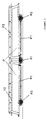
- FIG. 1 shows a wagon which incorporates three running gears R1, R2, R3 like that developed by the present invention.
- This wagon is of articulated construction and is formed by two platforms P, each with two levels P1, P2, which allow the vehicles to be loaded and unloaded, at the two levels, through their end faces, also allowing the vehicles to pass from one platform to another and to the adjacent wagons, in the case where various wagons like the one illustrated in Figure 1 are incorporated in a train.
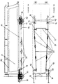
- the running gear R1 (and likewise the extreme running gears R2, R3) includes a carrying frame 1 in which are incorporated the axle boxes CC ( Figure 3) of each set of running gear, and likewise the necessary mechanisms for the translation and locking of the said sets.
- the said carrying frame 1 has, in its lateral parts, housings in which are incorporated suspension springs 2.
- Vertical dampers AV are mounted within the suspension springs 2.
- the carrying frame 1 also has, incorporated in its lateral parts, sliding shoes 3, on which the running gear R1 rests during the process of changing guages, such that the wheels W are unloaded and thus the translation from one gauge to another is greatly facilitated.
- suspension springs 2 bear on suspension headers 4, on which are also fixed the bells of the vertical dampers AV.
- the said suspension headers are stabilized by means of sets of arms 5 ( Figure 3).
- hanging suspension links 6 are provided, the upper ends of which are connected to the suspension headers 4, while the lower ends of the said hanging suspension links 6 are fixed to supports S which are integral with the frame of the wagon. That being so, the platforms P are suspended from the lower part of the said hanging suspension links 6, the load being transmitted from them to the suspension springs 2 via the said hanging suspension links 6.
- the hanging suspension links 6 generate a force for self-centring of the running gear R1 and, due to the inclination which they have with respect to the vertical plane transverse to the axis of the track, they provide a force countering the transverse movements between the platforms P and the running gear R1.
- FIG 3 also illustrates the braking system used in the running gear R1 of the invention (an identical braking system will also be mounted on the running gears R2, R3).
- This braking system is of the "calliper" type and comprises a pneumatic actuating cylinder 7, a calliper 8 and friction linings 9 which are applied by the cylinder 7 against half-discs fastened to the web of each wheel W.
- the pneumatic actuating cylinder 7, as well as the brake calliper 8 and the friction linings 9, are integral with a support 10 which is fixed to the inner axle box CC of the corresponding wheel W and can be moved as a whole with the set of running gear in order to adjust the braking system to both track guages and thus guarantee the correct operation thereof.
- the running gears R1, R2, R3 of the present invention are provided with guidance systems with the aim of ensuring that the angle which the rim of the wheel W forms with the tangent to a curve of the railway track at the point of contact with it is zero.
- the guidance system of the intermediate running gear R1 can be seen in Figure 3.
- This system on each side of the wagon, consists of a guidance lever arm 11 fitted in the carrying frame 1 of the running gear R1 in the horizontal position, and of two guide bars 12, 13, of which the bar 13 is connected at one end to the adjacent end face of one of the trailers constituting the wagon and the other bar 12 is connected at one end to the adjacent end face of the attached trailer. These connections have not been represented in Figure 3.
- the other ends of the bars 12, 13 are connected to the lever arm 11.
- lever arm 11 and the bar 12 have been represented in Figure 3 in two positions which they can adopt while the train is running: one corresponding to the train running in a straight line (lever arm 11 perpendicular to the wheel W in the drawing) and the other corresponding to the train running on a curve (lever arm 11 inclined with respect to the wheel W in the drawing).
- This guidance system when the train is on a curve, allows the end faces of the adjacent trailers to come closer to each other on the inside of the curve, pushing on the guide bars 12, 13 arranged on that side of the curve, which, in their turn, transmit the movement to the ends of the corresponding lever arm 11, causing the latter to turn about its spindle. Simultaneously, the end faces of both trailers move apart from one another on the outside of the curve, pulling the guide bars 12, 13 arranged on that side of the curve and they, in their turn, transmit a movement from the corresponding lever arm 11 turning about its spindle, of equal magnitude, but opposite in direction to the turning of the lever arm 11 situated on the inside of the curve. These movements are converted into a rotation of the bogie about its vertical axis, the latter being situated in a radial position with respect to the centre of the curve.
- the guiding of the extreme running gears R2, R3 differs from that of the intermediate running gear R1, since in the former case no use can be made of the help from the adjacent end face of an attached trailer.
- the basic principle employed for guiding the extreme running gears R2, R3 is the same and consists in taking advantage of the relative turning movement between the two articulated platforms P, which is transmitted by means of two mechanisms, one for control and the other for guidance, from the coupling of each of the platforms P to the positions of the running gears R2, R3 at both ends, where the guidance proper of these running gears is applied in a way similar to that of the guidance of the intermediate running gear R1.
- the guidance mechanism is formed by two lever arms 14 and two pairs of bars 15, 16.
- the guide bars 15 are connected at one end to their corresponding lever arm 14 and at the other end to bell cranks 17 which form part of a compensation mechanism.
- the guide bars 16 are also connected at one end to their corresponding lever arm 14 and at the other end to a support of the wagon.
- the control mechanism on each side of the trailer, consists of a control bar 18, one of whose ends is connected to the end face of the adjacent trailer and the other end is articulated to a lever arm 19. Between the lever arm 19 and the bell cranks 17 of the compensation mechanism, adjustable bars 20 are fitted, the longitudinal arms of the bell cranks 17 being connected together by means of a crossbar 21 which also forms part of the abovementioned compensation mechanism.
- Figures 5A and 5B respectively have been represented again in Figures 6A and 6B, also in plan and elevation view, but illustrating the position which the control and guidance mechanisms would take up when the articulated wagon set lies on a curve.
- the end faces of the adjacent trailers come closer on the inside of the curve and move apart on the outside, and the bar 18 on the inside of the curve pushes on the corresponding lever arm 19, while the other bar 18 situated on the outside of the curve pulls on the other lever arm 19.
- Both lever arms then turn by the same angle, but in opposite directions, around their respective spindles which are fixed to the structure of the trailer, being inclined as indicated in Figure 6B.
- the adjustable bars 20, pulled on by the lever arms 19, slide longitudinally on their support guides, which are integral with the frame of the trailer.
- the one which is working in tension (the bar on the inside of the curve according to Figure 6B) pulls on the corresponding bell crank 17 of the compensation mechanism and transmits the longitudinal movement to the bars 15, which shift the ends of the bogie in the opposite direction by means of the lever arms 14.
Abstract
Description
- a carrying frame in which are incorporated the axle boxes of each set of running gear and the mechanisms necessary for translating and locking the said sets;
- suspension springs incorporated in housings in the lateral parts of the carrying frame and provided with vertical dampers mounted inside them;
- sliding shoes incorporated in the lateral parts of the carrying frame and intended to support the running gear during the process of changing track gauge;
- suspension headers on which the upper parts of the suspension springs bear, and in which the bells of the vertical dampers are fixed;
- arms for stabilizing the suspension headers;
- hanging suspension links connected at their upper ends to the suspension headers and at their lower ends to corresponding supports integral with the frame of the wagon; and
- guidance systems for causing the angle formed by the rim of the wheel and the tangent to a curve of the track to be zero at the point of contact with the track.
- Figure 1 is a side elevation view of a car transporter platform which incorporates running gears of the present invention,
- Figure 2 is an elevation view, with sectioned parts, of the intermediate running gear of the platform of Figure 1,
- Figure 3 is a plan view, with sectioned parts, of the running gear of Figure 2,
- Figure 4 is a view, with sectioned parts, intended fundamentally to show the system for locking the axle boxes of the running gear of the invention,
- Figures 5A and 5B are elevation and plan views respectively, diagrammatically representing the guidance system used in running gears in accordance with the invention, and
- Figures 6A and 6B are plan and elevation views respectively, illustrating the position which the guidance system of Figures 5A and 5B would take up when the articulated wagon set lies on a curve.
Claims (6)
- Single-axle running gear with movable independent wheels for articulated car transporter wagons, which makes it possible to adapt such wagons, incorporated by two trailers connected together, so that they can run on two different track guages, and which includes two sets of running gear, each of which comprises a half-axle, a wheel (W), two brake discs integral with each other and two axle boxes (CC) which are mounted at both ends of the half-axle and which are fixed to it in the position corresponding to each track gauge by means of respective locking keys (L), characterized in that it comprises:a carrying frame (1) in which are incorporated the axle boxes (CC) of each set of running gear and the mechanisms necessary for translating and locking the said sets;suspension springs (2) incorporated in housings in the front parts of the carrying frame (1) and provided with vertical dampers (AV) mounted inside them;sliding shoes (3) incorporated in the lateral parts of the carrying frame (1) and intended to support the running gear (R1, R2, R3) during the process of changing track gauge;suspension headers (4) on which the upper parts of the suspension springs (2) bear, and in which the bells of the vertical dampers (AV) are fixed;arms (5) for stabilizing the suspension headers (4);hanging suspension links (6) connected at their upper ends to the suspension headers (4) and at their lower ends to supports (S) integral with the frame of the wagon; andsystems for guiding the running gear (R1, R2, R3) in order to cause the angle formed by the rim of each wheel (W) and the tangent to a curve of the track to be zero at the point of contact with the track.
- Running gear according to Claim 1, characterized in that each set of running gear carries two locking keys (L), one for each axle box (CC).
- Running gear according to Claim 1 or 2, characterized in that the brake of each set of running gear comprises a pneumatic actuating cylinder (7), a calliper (8) and friction linings (9) which are applied by the said cylinder (7) against half-discs fastened to the web of the corresponding wheel (W).
- Running gear according to Claim 3, characterized in that both the pneumatic actuating cylinder (7) and the brake calliper (8) with the friction linings (9) are integral with a support (10) which is fixed to the inner axle box (CC) of the corresponding wheel (W) and can be moved as a whole with the set of running gear in order to adjust the braking system to both track guages.
- Running gear according to any one of Claims 1 to 4, characterized in that, in the case of an intermediate running gear (R1) of a wagon, the running gear guidance system consists of two guidance lever arms (11) fitted in a horizontal position in the carrying frame (1) and of two pairs of guide bars (12, 13) which are fixed at one end to the said lever arms (11) and at their other end to the respective adjacent end faces of the two trailers constituting the wagon.
- Running gear according to any one of Claims 1 to 4, characterized in that, in the case of extreme running gears (R2, R3) of a wagon, the running gear guidance system consists of a control mechanism and of a guidance mechanism proper, of which the guidance mechanism is formed by two lever arms (14) and two pairs of bars (15, 16) which are connected at one end to the said lever arms (14), the other end of the first pair of bars (15) being connected to bell cranks (17) which form part of a compensation mechanism, and the other end of the second pair of bars (16) being connected to a support of the wagon, while the control mechanism consists of two control bars (18), one of whose ends is connected to the end face of the adjacent trailer and the other end is articulated to corresponding lever arms (19), adjustable bars (20) being fitted between the said lever arms (19) and the bell cranks (17) of the compensation mechanism, and the longitudinal arms of the said bell cranks (17) being connected together by means of a crossbar (21) which also forms part of the said compensation mechanism.
Priority Applications (1)
| Application Number | Priority Date | Filing Date | Title |
|---|---|---|---|
| SI9730435T SI0884231T1 (en) | 1996-12-24 | 1997-11-28 | Articulated railway carriage for the tranport of cars, provided with single-axle running gears with movable independent wheels |
Applications Claiming Priority (3)
| Application Number | Priority Date | Filing Date | Title |
|---|---|---|---|
| ES009602736A ES2133229B1 (en) | 1996-12-24 | 1996-12-24 | SINGLE AXIS ROLLER WITH INDEPENDENT MOVABLE WHEELS FOR ARTICULATED CARS FOR CAR TRANSPORTATION. |
| ES9602736 | 1996-12-24 | ||
| PCT/ES1997/000295 WO1998028176A1 (en) | 1996-12-24 | 1997-11-28 | Rolling monoaxle provided with movable independent wheels for articulated railway carriages intended to the transportation of cars |
Publications (2)
| Publication Number | Publication Date |
|---|---|
| EP0884231A1 true EP0884231A1 (en) | 1998-12-16 |
| EP0884231B1 EP0884231B1 (en) | 2002-10-16 |
Family
ID=8297147
Family Applications (1)
| Application Number | Title | Priority Date | Filing Date |
|---|---|---|---|
| EP97945884A Expired - Lifetime EP0884231B1 (en) | 1996-12-24 | 1997-11-28 | Articulated railway carriage for the tranport of cars, provided with single-axle running gears with movable independent wheels |
Country Status (20)
| Country | Link |
|---|---|
| US (1) | US6230631B1 (en) |
| EP (1) | EP0884231B1 (en) |
| JP (1) | JP3391029B2 (en) |
| CN (1) | CN1078551C (en) |
| AR (1) | AR010856A1 (en) |
| AT (1) | ATE226162T1 (en) |
| AU (1) | AU718793B2 (en) |
| CA (1) | CA2245929A1 (en) |
| DE (1) | DE69716406T2 (en) |
| DK (1) | DK0884231T3 (en) |
| EE (1) | EE03430B1 (en) |
| ES (1) | ES2133229B1 (en) |
| PL (1) | PL328581A1 (en) |
| PT (1) | PT884231E (en) |
| RU (1) | RU2198808C2 (en) |
| SI (1) | SI0884231T1 (en) |
| SK (1) | SK285021B6 (en) |
| TR (1) | TR199801647T1 (en) |
| UA (1) | UA41471C2 (en) |
| WO (1) | WO1998028176A1 (en) |
Cited By (2)
| Publication number | Priority date | Publication date | Assignee | Title |
|---|---|---|---|---|
| EP1180462A2 (en) | 2000-08-14 | 2002-02-20 | Patentes Talgo, S.A. | Single-axle wheel set with outer suspension supports for railway vehicles with pendulum-type suspension |
| WO2015150062A3 (en) * | 2014-03-31 | 2015-12-10 | Trojak Jürgen | Multi-part railway car having variable gauge wheelsets |
Families Citing this family (7)
| Publication number | Priority date | Publication date | Assignee | Title |
|---|---|---|---|---|
| ES2174685B2 (en) * | 1999-09-24 | 2004-08-01 | Construcciones Y Auxiliar De Ferrocarriles, S.A. | VIA WIDTH CHANGE SYSTEM, FOR A BOGIE OF MOTOR OR TOWED AXLES. |
| DE10047737A1 (en) * | 2000-09-27 | 2002-04-11 | Bombardier Transp Gmbh | Rail vehicle with a load carrier |
| ES2195756B1 (en) * | 2001-12-27 | 2005-03-01 | Patentes Talgo, S.A | SYSTEM TO OPTIMIZE THE GUIDE OF RAILWAY AXLES. |
| ES2316220B1 (en) | 2006-02-24 | 2010-01-12 | Patentes Talgo, S.L. | METHOD FOR OPTIMIZING GUIDANCE OF RAILWAY VEHICLES. |
| JP4838693B2 (en) * | 2006-11-27 | 2011-12-14 | 三菱重工業株式会社 | Track system |
| JP2011021414A (en) * | 2009-07-17 | 2011-02-03 | Nifco Inc | Assist device for movable body |
| CN107521519B (en) * | 2017-09-01 | 2023-07-11 | 西南交通大学 | Variable gauge bogie |
Family Cites Families (9)
| Publication number | Priority date | Publication date | Assignee | Title |
|---|---|---|---|---|
| NL167017B (en) * | 1951-06-26 | Boge Gmbh | ELASTIC MOTOR SUSPENSION ARM WITH HYDRAULIC DAMPING. | |
| NL197842A (en) * | 1955-02-10 | |||
| GB791678A (en) * | 1955-05-11 | 1958-03-12 | Acf Ind Inc | Articulated train with coupler steered axles |
| FR1558329A (en) * | 1966-10-19 | 1969-02-28 | ||
| US4480554A (en) * | 1979-07-23 | 1984-11-06 | Brodeur Rene H | Articulated rail car for vehicular trailers |
| US4637318A (en) * | 1985-02-08 | 1987-01-20 | Paton H N | Swivelable single axle railcar truck and railcar |
| US5001989A (en) * | 1989-02-21 | 1991-03-26 | Amsted Industries Incorporated | Single axle suspension system for railway car truck |
| IT1272720B (en) * | 1993-10-01 | 1997-06-26 | Costamasnaga Spa | DEVICE FOR ORIENTING THE AXES OF A CURVED RAILWAY VEHICLE |
| US5524552A (en) * | 1994-07-08 | 1996-06-11 | National Castings Incorporated | Single axle truck for large railroad cars |
-
1996
- 1996-12-24 ES ES009602736A patent/ES2133229B1/en not_active Expired - Fee Related
-
1997
- 1997-11-28 DE DE69716406T patent/DE69716406T2/en not_active Expired - Fee Related
- 1997-11-28 SK SK1156-98A patent/SK285021B6/en not_active IP Right Cessation
- 1997-11-28 CA CA002245929A patent/CA2245929A1/en not_active Abandoned
- 1997-11-28 EE EE9800253A patent/EE03430B1/en not_active IP Right Cessation
- 1997-11-28 PT PT97945884T patent/PT884231E/en unknown
- 1997-11-28 UA UA98084543A patent/UA41471C2/en unknown
- 1997-11-28 RU RU98117839/28A patent/RU2198808C2/en not_active IP Right Cessation
- 1997-11-28 PL PL97328581A patent/PL328581A1/en unknown
- 1997-11-28 DK DK97945884T patent/DK0884231T3/en active
- 1997-11-28 TR TR1998/01647T patent/TR199801647T1/en unknown
- 1997-11-28 AT AT97945884T patent/ATE226162T1/en not_active IP Right Cessation
- 1997-11-28 US US09/125,213 patent/US6230631B1/en not_active Expired - Fee Related
- 1997-11-28 EP EP97945884A patent/EP0884231B1/en not_active Expired - Lifetime
- 1997-11-28 SI SI9730435T patent/SI0884231T1/en unknown
- 1997-11-28 JP JP52843498A patent/JP3391029B2/en not_active Expired - Fee Related
- 1997-11-28 CN CN97192360A patent/CN1078551C/en not_active Expired - Fee Related
- 1997-11-28 WO PCT/ES1997/000295 patent/WO1998028176A1/en active IP Right Grant
- 1997-11-28 AU AU51223/98A patent/AU718793B2/en not_active Ceased
- 1997-12-23 AR ARP970106161A patent/AR010856A1/en unknown
Non-Patent Citations (1)
| Title |
|---|
| See references of WO9828176A1 * |
Cited By (4)
| Publication number | Priority date | Publication date | Assignee | Title |
|---|---|---|---|---|
| EP1180462A2 (en) | 2000-08-14 | 2002-02-20 | Patentes Talgo, S.A. | Single-axle wheel set with outer suspension supports for railway vehicles with pendulum-type suspension |
| EP1180462A3 (en) * | 2000-08-14 | 2002-09-18 | Patentes Talgo, S.A. | Single-axle wheel set with outer suspension supports for railway vehicles with pendulum-type suspension |
| WO2015150062A3 (en) * | 2014-03-31 | 2015-12-10 | Trojak Jürgen | Multi-part railway car having variable gauge wheelsets |
| EA034314B1 (en) * | 2014-03-31 | 2020-01-28 | Юрген Тройак | Multi-part railway car |
Also Published As
| Publication number | Publication date |
|---|---|
| DK0884231T3 (en) | 2003-02-17 |
| EE9800253A (en) | 1999-02-15 |
| EP0884231B1 (en) | 2002-10-16 |
| DE69716406D1 (en) | 2002-11-21 |
| PL328581A1 (en) | 1999-02-01 |
| DE69716406T2 (en) | 2003-06-05 |
| ES2133229B1 (en) | 2000-04-16 |
| RU2198808C2 (en) | 2003-02-20 |
| WO1998028176A1 (en) | 1998-07-02 |
| JP2000505761A (en) | 2000-05-16 |
| SI0884231T1 (en) | 2003-04-30 |
| AU718793B2 (en) | 2000-04-20 |
| ATE226162T1 (en) | 2002-11-15 |
| AU5122398A (en) | 1998-07-17 |
| PT884231E (en) | 2003-03-31 |
| SK115698A3 (en) | 1999-04-13 |
| CA2245929A1 (en) | 1998-07-02 |
| CN1211219A (en) | 1999-03-17 |
| US6230631B1 (en) | 2001-05-15 |
| TR199801647T1 (en) | 1999-05-21 |
| ES2133229A1 (en) | 1999-09-01 |
| SK285021B6 (en) | 2006-04-06 |
| JP3391029B2 (en) | 2003-03-31 |
| UA41471C2 (en) | 2001-09-17 |
| AR010856A1 (en) | 2000-07-12 |
| EE03430B1 (en) | 2001-06-15 |
| CN1078551C (en) | 2002-01-30 |
Similar Documents
| Publication | Publication Date | Title |
|---|---|---|
| CA1115126A (en) | Articulated railway vehicle carried on radial single wheel sets | |
| KR101165711B1 (en) | Simplified truck mounted brake system | |
| US4274776A (en) | Depressed center spine piggyback/container railcar | |
| EP0007226B1 (en) | Radial truck for railway vehicle | |
| RU2123951C1 (en) | Guide system for two four-wheel bogies with adjustable wheel-to-wheel cross distance and guide system for four-wheel bogie with adjustable wheel-to-wheel cross distance | |
| CN102239075A (en) | Improved variable-width bogie with rotating axles | |
| EP0884231B1 (en) | Articulated railway carriage for the tranport of cars, provided with single-axle running gears with movable independent wheels | |
| US4411202A (en) | Rail vehicle | |
| JPH08216881A (en) | Gauge variable truck for rolling stock | |
| US5802981A (en) | Twelve-axle rail vehicle | |
| NO173923B (en) | TRAIN UNIT, PRIOR TO TRANSPORTING LOADED VEHICLES | |
| US5020446A (en) | Three-dimensional single-wheel suspension for wheels of railed vehicles | |
| RU98117839A (en) | ONE-AXIAL RUNNING MECHANISM WITH MOBILE INDEPENDENT WHEELS FOR JOINED CARS FOR TRANSPORTATION OF VEHICLES | |
| US4729324A (en) | Multiple axle self-steering powered locomotive truck | |
| JPH078647B2 (en) | Orbital vehicle | |
| US4817535A (en) | Stand alone well car with double axle suspension system | |
| US2881713A (en) | Rail vehicle with low platform | |
| CZ288124B6 (en) | Single running gear for rail vehicles | |
| JPH08169338A (en) | Variable gage bogie and gage changer device for rolling stock | |
| US2135728A (en) | Truck | |
| RU2301752C1 (en) | Six-axle rail vehicle with three-axle bogies (versions) | |
| US3250231A (en) | Articulated railway truck | |
| SU1622208A1 (en) | Freight car boggie | |
| US5421269A (en) | Radially adjustable running gear for a railborne vehicle | |
| US2208628A (en) | Railway vehicle |
Legal Events
| Date | Code | Title | Description |
|---|---|---|---|
| PUAI | Public reference made under article 153(3) epc to a published international application that has entered the european phase |
Free format text: ORIGINAL CODE: 0009012 |
|
| 17P | Request for examination filed |
Effective date: 19980807 |
|
| AK | Designated contracting states |
Kind code of ref document: A1 Designated state(s): AT BE CH DE DK ES FI FR GB GR IE IT LI LU MC NL PT SE |
|
| AX | Request for extension of the european patent |
Free format text: AL PAYMENT 980807;LT PAYMENT 980807;LV PAYMENT 980807;RO PAYMENT 980807;SI PAYMENT 980807 |
|
| 17Q | First examination report despatched |
Effective date: 20010515 |
|
| GRAG | Despatch of communication of intention to grant |
Free format text: ORIGINAL CODE: EPIDOS AGRA |
|
| RTI1 | Title (correction) |
Free format text: ARTICULATED RAILWAY CARRIAGE FOR THE TRANPORT OF CARS, PROVIDED WITH SINGLE-AXLE RUNNING GEARS WITH MOVABLE INDEPENDENT WHEELS |
|
| RTI1 | Title (correction) |
Free format text: ARTICULATED RAILWAY CARRIAGE FOR THE TRANPORT OF CARS, PROVIDED WITH SINGLE-AXLE RUNNING GEARS WITH MOVABLE INDEPENDENT WHEELS |
|
| GRAG | Despatch of communication of intention to grant |
Free format text: ORIGINAL CODE: EPIDOS AGRA |
|
| GRAH | Despatch of communication of intention to grant a patent |
Free format text: ORIGINAL CODE: EPIDOS IGRA |
|
| GRAA | (expected) grant |
Free format text: ORIGINAL CODE: 0009210 |
|
| GRAH | Despatch of communication of intention to grant a patent |
Free format text: ORIGINAL CODE: EPIDOS IGRA |
|
| AK | Designated contracting states |
Kind code of ref document: B1 Designated state(s): AT BE CH DE DK ES FI FR GB GR IE IT LI LU MC NL PT SE |
|
| AX | Request for extension of the european patent |
Free format text: AL PAYMENT 19980807;LT PAYMENT 19980807;LV PAYMENT 19980807;RO PAYMENT 19980807;SI PAYMENT 19980807 |
|
| REF | Corresponds to: |
Ref document number: 226162 Country of ref document: AT Date of ref document: 20021115 Kind code of ref document: T |
|
| REG | Reference to a national code |
Ref country code: GB Ref legal event code: FG4D |
|
| REG | Reference to a national code |
Ref country code: CH Ref legal event code: EP |
|
| REG | Reference to a national code |
Ref country code: IE Ref legal event code: FG4D |
|
| REF | Corresponds to: |
Ref document number: 69716406 Country of ref document: DE Date of ref document: 20021121 |
|
| REG | Reference to a national code |
Ref country code: DK Ref legal event code: T3 |
|
| REG | Reference to a national code |
Ref country code: GR Ref legal event code: EP Ref document number: 20030400261 Country of ref document: GR |
|
| REG | Reference to a national code |
Ref country code: CH Ref legal event code: NV Representative=s name: E. BLUM & CO. PATENTANWAELTE |
|
| REG | Reference to a national code |
Ref country code: PT Ref legal event code: SC4A Free format text: AVAILABILITY OF NATIONAL TRANSLATION Effective date: 20030114 |
|
| PG25 | Lapsed in a contracting state [announced via postgrant information from national office to epo] |
Ref country code: ES Free format text: LAPSE BECAUSE OF FAILURE TO SUBMIT A TRANSLATION OF THE DESCRIPTION OR TO PAY THE FEE WITHIN THE PRESCRIBED TIME-LIMIT Effective date: 20030429 |
|
| ET | Fr: translation filed | ||
| PLBE | No opposition filed within time limit |
Free format text: ORIGINAL CODE: 0009261 |
|
| STAA | Information on the status of an ep patent application or granted ep patent |
Free format text: STATUS: NO OPPOSITION FILED WITHIN TIME LIMIT |
|
| 26N | No opposition filed |
Effective date: 20030717 |
|
| PGFP | Annual fee paid to national office [announced via postgrant information from national office to epo] |
Ref country code: MC Payment date: 20031010 Year of fee payment: 7 |
|
| PGFP | Annual fee paid to national office [announced via postgrant information from national office to epo] |
Ref country code: NL Payment date: 20031105 Year of fee payment: 7 |
|
| PGFP | Annual fee paid to national office [announced via postgrant information from national office to epo] |
Ref country code: AT Payment date: 20031112 Year of fee payment: 7 |
|
| PGFP | Annual fee paid to national office [announced via postgrant information from national office to epo] |
Ref country code: LU Payment date: 20031125 Year of fee payment: 7 |
|
| PGFP | Annual fee paid to national office [announced via postgrant information from national office to epo] |
Ref country code: IE Payment date: 20031127 Year of fee payment: 7 |
|
| PGFP | Annual fee paid to national office [announced via postgrant information from national office to epo] |
Ref country code: PT Payment date: 20031202 Year of fee payment: 7 |
|
| PG25 | Lapsed in a contracting state [announced via postgrant information from national office to epo] |
Ref country code: LU Free format text: LAPSE BECAUSE OF NON-PAYMENT OF DUE FEES Effective date: 20041128 Ref country code: AT Free format text: LAPSE BECAUSE OF NON-PAYMENT OF DUE FEES Effective date: 20041128 |
|
| PG25 | Lapsed in a contracting state [announced via postgrant information from national office to epo] |
Ref country code: IE Free format text: LAPSE BECAUSE OF NON-PAYMENT OF DUE FEES Effective date: 20041129 |
|
| PG25 | Lapsed in a contracting state [announced via postgrant information from national office to epo] |
Ref country code: MC Free format text: LAPSE BECAUSE OF NON-PAYMENT OF DUE FEES Effective date: 20041130 |
|
| REG | Reference to a national code |
Ref country code: SI Ref legal event code: IF |
|
| PG25 | Lapsed in a contracting state [announced via postgrant information from national office to epo] |
Ref country code: PT Free format text: LAPSE BECAUSE OF NON-PAYMENT OF DUE FEES Effective date: 20050530 |
|
| PG25 | Lapsed in a contracting state [announced via postgrant information from national office to epo] |
Ref country code: NL Free format text: LAPSE BECAUSE OF NON-PAYMENT OF DUE FEES Effective date: 20050601 |
|
| REG | Reference to a national code |
Ref country code: PT Ref legal event code: MM4A Effective date: 20050530 |
|
| NLV4 | Nl: lapsed or anulled due to non-payment of the annual fee |
Effective date: 20050601 |
|
| REG | Reference to a national code |
Ref country code: IE Ref legal event code: MM4A |
|
| REG | Reference to a national code |
Ref country code: SI Ref legal event code: KO00 Effective date: 20050822 |
|
| REG | Reference to a national code |
Ref country code: CH Ref legal event code: PFA Owner name: PATENTES TALGO, S.A. Free format text: PATENTES TALGO, S.A.#MONTALBAN, 14#28014 MADRID (ES) -TRANSFER TO- PATENTES TALGO, S.A.#MONTALBAN, 14#28014 MADRID (ES) |
|
| PGFP | Annual fee paid to national office [announced via postgrant information from national office to epo] |
Ref country code: DK Payment date: 20081114 Year of fee payment: 12 Ref country code: DE Payment date: 20081120 Year of fee payment: 12 Ref country code: CH Payment date: 20081130 Year of fee payment: 12 |
|
| PGFP | Annual fee paid to national office [announced via postgrant information from national office to epo] |
Ref country code: FI Payment date: 20081112 Year of fee payment: 12 |
|
| PGFP | Annual fee paid to national office [announced via postgrant information from national office to epo] |
Ref country code: IT Payment date: 20081127 Year of fee payment: 12 Ref country code: BE Payment date: 20081110 Year of fee payment: 12 Ref country code: SE Payment date: 20081107 Year of fee payment: 12 |
|
| PGFP | Annual fee paid to national office [announced via postgrant information from national office to epo] |
Ref country code: FR Payment date: 20081112 Year of fee payment: 12 |
|
| PGFP | Annual fee paid to national office [announced via postgrant information from national office to epo] |
Ref country code: GR Payment date: 20081016 Year of fee payment: 12 Ref country code: GB Payment date: 20081126 Year of fee payment: 12 |
|
| BERE | Be: lapsed |
Owner name: S.A. *PATENTES TALGO Effective date: 20091130 |
|
| EUG | Se: european patent has lapsed | ||
| REG | Reference to a national code |
Ref country code: CH Ref legal event code: PL |
|
| REG | Reference to a national code |
Ref country code: DK Ref legal event code: EBP |
|
| GBPC | Gb: european patent ceased through non-payment of renewal fee |
Effective date: 20091128 |
|
| REG | Reference to a national code |
Ref country code: FR Ref legal event code: ST Effective date: 20100730 |
|
| PG25 | Lapsed in a contracting state [announced via postgrant information from national office to epo] |
Ref country code: FI Free format text: LAPSE BECAUSE OF NON-PAYMENT OF DUE FEES Effective date: 20091128 |
|
| PG25 | Lapsed in a contracting state [announced via postgrant information from national office to epo] |
Ref country code: LI Free format text: LAPSE BECAUSE OF NON-PAYMENT OF DUE FEES Effective date: 20091130 Ref country code: GR Free format text: LAPSE BECAUSE OF NON-PAYMENT OF DUE FEES Effective date: 20100602 Ref country code: FR Free format text: LAPSE BECAUSE OF NON-PAYMENT OF DUE FEES Effective date: 20091130 Ref country code: CH Free format text: LAPSE BECAUSE OF NON-PAYMENT OF DUE FEES Effective date: 20091130 Ref country code: BE Free format text: LAPSE BECAUSE OF NON-PAYMENT OF DUE FEES Effective date: 20091130 |
|
| PG25 | Lapsed in a contracting state [announced via postgrant information from national office to epo] |
Ref country code: DE Free format text: LAPSE BECAUSE OF NON-PAYMENT OF DUE FEES Effective date: 20100601 |
|
| PG25 | Lapsed in a contracting state [announced via postgrant information from national office to epo] |
Ref country code: GB Free format text: LAPSE BECAUSE OF NON-PAYMENT OF DUE FEES Effective date: 20091128 |
|
| PG25 | Lapsed in a contracting state [announced via postgrant information from national office to epo] |
Ref country code: DK Free format text: LAPSE BECAUSE OF NON-PAYMENT OF DUE FEES Effective date: 20091130 |
|
| PG25 | Lapsed in a contracting state [announced via postgrant information from national office to epo] |
Ref country code: IT Free format text: LAPSE BECAUSE OF NON-PAYMENT OF DUE FEES Effective date: 20091128 |
|
| PG25 | Lapsed in a contracting state [announced via postgrant information from national office to epo] |
Ref country code: SE Free format text: LAPSE BECAUSE OF NON-PAYMENT OF DUE FEES Effective date: 20091129 |