EP0882860A2 - Solenoidaktivierte Riegelsteuerung für ein elektronisches Schloss - Google Patents
Solenoidaktivierte Riegelsteuerung für ein elektronisches Schloss Download PDFInfo
- Publication number
- EP0882860A2 EP0882860A2 EP19980303570 EP98303570A EP0882860A2 EP 0882860 A2 EP0882860 A2 EP 0882860A2 EP 19980303570 EP19980303570 EP 19980303570 EP 98303570 A EP98303570 A EP 98303570A EP 0882860 A2 EP0882860 A2 EP 0882860A2
- Authority
- EP
- European Patent Office
- Prior art keywords
- bolt
- latch
- slide
- lock
- lever
- Prior art date
- Legal status (The legal status is an assumption and is not a legal conclusion. Google has not performed a legal analysis and makes no representation as to the accuracy of the status listed.)
- Withdrawn
Links
- 230000007246 mechanism Effects 0.000 claims description 16
- WYTGDNHDOZPMIW-RCBQFDQVSA-N alstonine Natural products C1=CC2=C3C=CC=CC3=NC2=C2N1C[C@H]1[C@H](C)OC=C(C(=O)OC)[C@H]1C2 WYTGDNHDOZPMIW-RCBQFDQVSA-N 0.000 claims description 11
- 230000000903 blocking effect Effects 0.000 claims description 9
- 238000006073 displacement reaction Methods 0.000 claims description 3
- 239000003990 capacitor Substances 0.000 description 5
- 238000007789 sealing Methods 0.000 description 4
- 230000009471 action Effects 0.000 description 3
- 230000008901 benefit Effects 0.000 description 3
- 230000005389 magnetism Effects 0.000 description 3
- 125000006850 spacer group Chemical group 0.000 description 3
- 230000003750 conditioning effect Effects 0.000 description 2
- 238000010586 diagram Methods 0.000 description 2
- 230000000694 effects Effects 0.000 description 2
- 230000004044 response Effects 0.000 description 2
- 230000032683 aging Effects 0.000 description 1
- 230000007797 corrosion Effects 0.000 description 1
- 238000005260 corrosion Methods 0.000 description 1
- 230000004907 flux Effects 0.000 description 1
- 230000004048 modification Effects 0.000 description 1
- 238000012986 modification Methods 0.000 description 1
- 230000000717 retained effect Effects 0.000 description 1
- 230000035939 shock Effects 0.000 description 1
- 238000006467 substitution reaction Methods 0.000 description 1
Images


Classifications
-
- E—FIXED CONSTRUCTIONS
- E05—LOCKS; KEYS; WINDOW OR DOOR FITTINGS; SAFES
- E05B—LOCKS; ACCESSORIES THEREFOR; HANDCUFFS
- E05B47/00—Operating or controlling locks or other fastening devices by electric or magnetic means
- E05B47/06—Controlling mechanically-operated bolts by electro-magnetically-operated detents
- E05B47/0676—Controlling mechanically-operated bolts by electro-magnetically-operated detents by disconnecting the handle
- E05B47/0684—Controlling mechanically-operated bolts by electro-magnetically-operated detents by disconnecting the handle radially
- E05B47/0688—Controlling mechanically-operated bolts by electro-magnetically-operated detents by disconnecting the handle radially with a pivotally moveable coupling element
-
- E—FIXED CONSTRUCTIONS
- E05—LOCKS; KEYS; WINDOW OR DOOR FITTINGS; SAFES
- E05B—LOCKS; ACCESSORIES THEREFOR; HANDCUFFS
- E05B47/00—Operating or controlling locks or other fastening devices by electric or magnetic means
- E05B47/02—Movement of the bolt by electromagnetic means; Adaptation of locks, latches, or parts thereof, for movement of the bolt by electromagnetic means
-
- E—FIXED CONSTRUCTIONS
- E05—LOCKS; KEYS; WINDOW OR DOOR FITTINGS; SAFES
- E05B—LOCKS; ACCESSORIES THEREFOR; HANDCUFFS
- E05B15/00—Other details of locks; Parts for engagement by bolts of fastening devices
- E05B15/04—Spring arrangements in locks
-
- E—FIXED CONSTRUCTIONS
- E05—LOCKS; KEYS; WINDOW OR DOOR FITTINGS; SAFES
- E05B—LOCKS; ACCESSORIES THEREFOR; HANDCUFFS
- E05B37/00—Permutation or combination locks; Puzzle locks
-
- E—FIXED CONSTRUCTIONS
- E05—LOCKS; KEYS; WINDOW OR DOOR FITTINGS; SAFES
- E05B—LOCKS; ACCESSORIES THEREFOR; HANDCUFFS
- E05B47/00—Operating or controlling locks or other fastening devices by electric or magnetic means
- E05B47/0001—Operating or controlling locks or other fastening devices by electric or magnetic means with electric actuators; Constructional features thereof
- E05B47/0002—Operating or controlling locks or other fastening devices by electric or magnetic means with electric actuators; Constructional features thereof with electromagnets
-
- G—PHYSICS
- G07—CHECKING-DEVICES
- G07C—TIME OR ATTENDANCE REGISTERS; REGISTERING OR INDICATING THE WORKING OF MACHINES; GENERATING RANDOM NUMBERS; VOTING OR LOTTERY APPARATUS; ARRANGEMENTS, SYSTEMS OR APPARATUS FOR CHECKING NOT PROVIDED FOR ELSEWHERE
- G07C9/00—Individual registration on entry or exit
- G07C9/00174—Electronically operated locks; Circuits therefor; Nonmechanical keys therefor, e.g. passive or active electrical keys or other data carriers without mechanical keys
- G07C9/00896—Electronically operated locks; Circuits therefor; Nonmechanical keys therefor, e.g. passive or active electrical keys or other data carriers without mechanical keys specially adapted for particular uses
- G07C9/00912—Electronically operated locks; Circuits therefor; Nonmechanical keys therefor, e.g. passive or active electrical keys or other data carriers without mechanical keys specially adapted for particular uses for safes, strong-rooms, vaults or the like
-
- E—FIXED CONSTRUCTIONS
- E05—LOCKS; KEYS; WINDOW OR DOOR FITTINGS; SAFES
- E05B—LOCKS; ACCESSORIES THEREFOR; HANDCUFFS
- E05B47/00—Operating or controlling locks or other fastening devices by electric or magnetic means
- E05B2047/0048—Circuits, feeding, monitoring
- E05B2047/0057—Feeding
- E05B2047/0062—Feeding by generator
-
- E—FIXED CONSTRUCTIONS
- E05—LOCKS; KEYS; WINDOW OR DOOR FITTINGS; SAFES
- E05B—LOCKS; ACCESSORIES THEREFOR; HANDCUFFS
- E05B47/00—Operating or controlling locks or other fastening devices by electric or magnetic means
- E05B47/0001—Operating or controlling locks or other fastening devices by electric or magnetic means with electric actuators; Constructional features thereof
- E05B47/0002—Operating or controlling locks or other fastening devices by electric or magnetic means with electric actuators; Constructional features thereof with electromagnets
- E05B47/0006—Operating or controlling locks or other fastening devices by electric or magnetic means with electric actuators; Constructional features thereof with electromagnets having a non-movable core; with permanent magnet
-
- E—FIXED CONSTRUCTIONS
- E05—LOCKS; KEYS; WINDOW OR DOOR FITTINGS; SAFES
- E05B—LOCKS; ACCESSORIES THEREFOR; HANDCUFFS
- E05B49/00—Electric permutation locks; Circuits therefor ; Mechanical aspects of electronic locks; Mechanical keys therefor
-
- Y—GENERAL TAGGING OF NEW TECHNOLOGICAL DEVELOPMENTS; GENERAL TAGGING OF CROSS-SECTIONAL TECHNOLOGIES SPANNING OVER SEVERAL SECTIONS OF THE IPC; TECHNICAL SUBJECTS COVERED BY FORMER USPC CROSS-REFERENCE ART COLLECTIONS [XRACs] AND DIGESTS
- Y10—TECHNICAL SUBJECTS COVERED BY FORMER USPC
- Y10T—TECHNICAL SUBJECTS COVERED BY FORMER US CLASSIFICATION
- Y10T70/00—Locks
- Y10T70/70—Operating mechanism
- Y10T70/7051—Using a powered device [e.g., motor]
- Y10T70/7062—Electrical type [e.g., solenoid]
- Y10T70/7102—And details of blocking system [e.g., linkage, latch, pawl, spring]
-
- Y—GENERAL TAGGING OF NEW TECHNOLOGICAL DEVELOPMENTS; GENERAL TAGGING OF CROSS-SECTIONAL TECHNOLOGIES SPANNING OVER SEVERAL SECTIONS OF THE IPC; TECHNICAL SUBJECTS COVERED BY FORMER USPC CROSS-REFERENCE ART COLLECTIONS [XRACs] AND DIGESTS
- Y10—TECHNICAL SUBJECTS COVERED BY FORMER USPC
- Y10T—TECHNICAL SUBJECTS COVERED BY FORMER US CLASSIFICATION
- Y10T70/00—Locks
- Y10T70/70—Operating mechanism
- Y10T70/7153—Combination
- Y10T70/7181—Tumbler type
- Y10T70/7198—Single tumbler set
- Y10T70/7237—Rotary or swinging tumblers
- Y10T70/7243—Interset tumblers
- Y10T70/7249—Tumblers released
- Y10T70/7254—Fence held spaced from tumblers
-
- Y—GENERAL TAGGING OF NEW TECHNOLOGICAL DEVELOPMENTS; GENERAL TAGGING OF CROSS-SECTIONAL TECHNOLOGIES SPANNING OVER SEVERAL SECTIONS OF THE IPC; TECHNICAL SUBJECTS COVERED BY FORMER USPC CROSS-REFERENCE ART COLLECTIONS [XRACs] AND DIGESTS
- Y10—TECHNICAL SUBJECTS COVERED BY FORMER USPC
- Y10T—TECHNICAL SUBJECTS COVERED BY FORMER US CLASSIFICATION
- Y10T70/00—Locks
- Y10T70/70—Operating mechanism
- Y10T70/7153—Combination
- Y10T70/7424—Tampering prevention or attach defeating
Definitions
- This invention relates to electronic combination locks and more specifically to electronic combination locks having low-level power sources or reserves and a relatively large power consumer, such as a solenoid, to control the unlocking of the bolt.
- the stepper motor/generator of the electronic combination locks are capable of producing open circuit voltages well in excess of approximately sixteen volts during manual rotation, sufficient to charge capacitors to a level adequate to power the lock.
- the capacitor typically used with the X-07, Cencon and Auditcon Locks lacks the storage capacity to power the electronic control and provide the electrical current and power to operate a solenoid which may be used to control the mechanical chain of parts to drive the bolt from the extended position to a retracted, unlocked position.
- a typical solenoid consumes too much power to pick and hold for the device to be practical in very low-level powered devices.
- the relatively large power consumption of a solenoid has dictated that electronic locks use either an alternative low-power consumption device such as a pulsed stepper motor, which has stable states as in the above Mas-Hamilton locks, or a battery or utility power supply connection in order to provide adequate power for a solenoid controlled device.
- the power source must maintain sufficient electrical power to operate the electrical controls of the lock pick and hold the solenoid or other device such as the stepper motor until the lock is unlocked and the bolt control activated to permit the retraction of the bolt.
- solenoid controlled locks examples include United States Patent 5,307,656 issued to Gartner, et.al. and United States Patent 4,831,851 issued to Wayne F. Larson.
- the Gartner, et.al. lock is not disclosed as self-powered and, accordingly, a power supply such as a utility power source or a battery typically would be required to ensure operation of the lock, and the Larson lock is battery powered.
- Solenoids have a characteristic of magnetically sealing the armature in an actuated position as a result of the coercitivity of the solenoid core and the residual magnetism in the body of the solenoid.
- This magnetic sealing and holding is normally addressed as an undesirable characteristic by the inclusion of a non-magnetic spacer between the solenoid body and the armature plate of the solenoid.
- the non-magnetic spacer prevents the armature plate from being pulled close enough to the solenoid body to be retained by the residual magnetic field of the core and solenoid.
- the pulse solenoid will pick and hold until the magnetic seal is released by physical force exerted on the solenoid armature.
- This magnetic sealing may be advantageously used in the right circumstances to permit the use of a much shorter and smaller pulse of energy by the solenoid in order to derive the desired mechanical displacement and mechanical action necessary to the operation of the lock.
- the bolt lever is used to withdraw the bolt of an electronic combination lock.
- the bolt lever is controlled by a slide which, in turn, is locked from movement by a latch.
- the latch is activated for slide release by a solenoid pulsed with a very brief current flow controlled by an electronic signal from an electronic control such as a micro-processor.
- the solenoid pushes the latch lever out of blocking engagement with the slide, thereby releasing the slide for movement under the influence of a spring connected to the bolt lever and thus acting indirectly on the slide.
- the bolt lever and the slide are interconnected or engaged with each other such that movement of the bolt lever will displace the slide whenever released by a solenoid and a latch, thereby permitting the bolt lever to effect withdrawal of the bolt whenever the bolt lever is moved by a mechanical retraction device in the lock.
- the spring force on the bolt lever provides the displacing force to move the slide as well as the bolt lever from a position corresponding to a locked position for the lock to a displaced position corresponding to an unlocked condition for the lock.
- the solenoid armature plate seals to the body of the solenoid in its activated or picked condition due to the residual magnetism in the solenoid.
- the armature remains in the sealed condition until such time as the magnetic seal is broken by a mechanical force displacing the armature and armature plate relative to the solenoid body.
- the seal is broken by the armature plate being physically displaced to a position distanced from the solenoid body that the residual magnetic attractive force of the residual magnetic field is insufficient to hold the plate of the armature and, therefore, the spring connected to the latch lever is effective to return the solenoid armature to the unactuated or unpicked position.
- the mechanical force required to break the magnetic seal typically is relatively small (in the order of a few grams) for smaller solenoids.
- the mechanical force to break the magnetic seal is derived from movement of a slide containing the bolt lever.
- the solenoid After power removal, the solenoid remains in its actuated condition until the solenoid armature is unsealed from the solenoid body by the slide being displaced at least a distance sufficient to ensure that the unlocking operation of the lock will occur.
- the latch that normally blocks movement of the slide is allowed to partially restore to an intermediate position and then to fully restore upon the restoration of the slide to its fully restored position. This eliminates the possibility that the slide is not reset and latched at or before the restoration of the bolt lever and bolt to an extended locked position.
- the path of movement for the bolt lever and particularly a tenon thereon may be blocked by a portion of the slide primarily intended to prevent the bolt lever from being moved to a position permitting the opening of the bolt.
- the slide structure creates a condition which could prevent the locking of the lock.
- This problem is addressed by forming the slide to incorporate a serpentine beam spring that deflects to permit the passage of the tenon of the bolt lever.
- the serpentine beam spring and the slide cooperate to form a latch to prevent movement of the bolt lever under forced conditions while yet permitting restoration of the slide prior to the restoration of the bolt lever.
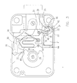
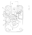
- Figs 1-7 are illustrations of the bolt control mechanism of the lock in various stages of operation.
- Fig. 8 is a block diagram of the electronic controls that control the solenoid of the lock in Figs. 1-7.
- a lock embodying the invention is illustrated in its locked and unactivated condition.
- Lock 10 is contained within lock housing 12 which, in turn, supports lock bolt 14 for reciprocal movement between an extended and withdrawn position.
- the force necessary to displace lock bolt 14 from one of its positions to another of its positions is provided to lock bolt 14 by bolt lever 16, which is pivotally connected to lock bolt 14 at pivot connection 18.
- Pivot connection 18 preferably is a bolt screwed into bolt lever 16 through lock bolt 14.
- bolt lever 16 has a tenon 20 protruding from one surface thereof, the back surface as illustrated in Fig. 1.
- Bolt lever 16 is further provided with a conventional nose portion 22 which may be displaced about pivot connection 18 to engage a cam slot 24 in cam wheel 26.
- Slide 28 is formed defining a slot 30 therein. Slot 30 is the residence for tenon 20 and any movement of slide 28 will cause a corresponding movement of tenon 20 and bolt lever 16 along with slide 28.
- slide 28 In order to engage nose piece 22 into cam slot 24, slide 28 must move downward as viewed in Figs.1-3. The downward movement of slide 28 is blocked by latch 32 engaging latch notch 33 of slide 28. Latch 32 is pivoted at latch pivot 31 to the lock housing 12.
- Solenoid reset lever 34 is operative to restore the solenoid armature 42 from its sealed to its unsealed condition, as will be explained more fully later.
- Solenoid 40 is mounted within the lock housing 12.
- Solenoid 40 is a conventional push solenoid with its armature 42 disposed coaxially with solenoid 40.
- the armature plate 44 is a part of or attached to armature 42 which extends entirely through the length of the solenoid 40. In operation, armature 42 will extend from the right end of the solenoid 40; the extension of the armature 42 is accomplished by the magnetic attraction of armature 42 and armature plate 44 toward the solenoid 40.
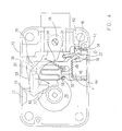
- Fig. 2 illustrates slide 28 in its raised position as a result of the engagement of nose portion 22 with the high dwell 48 on cam 26.
- Fig. 2 illustrates slide 28 in its raised position as a result of the engagement of nose portion 22 with the high dwell 48 on cam 26.
- bolt lever 16 With the high dwell 48 engaged by the nose portion 22 of bolt lever 16, bolt lever 16 will be displaced clockwise about pivot connection 18 and tenon 20 will act against the upper surface of slide slot 30, thus displacing slide 28 in an upward direction.
- notch 33 will be disengaged from latch 32 and latch 32 will be freed for movement.
- latch 32 With the slide 28 raised, as illustrated in Fig. 2, latch 32 is freed for pivoting counter-clockwise around latch pivot 31. Solenoid 40 is energized and armature 42 is extended from the right end of the solenoid 40 to pivot latch 32.
- Latch 32 is shown in Fig. 3 in its disengaged or unlatched position as a result of extension of armature 42 against a latch input tab 46.
- the engaging portion of latch 32 is disengaged from latch notch 33, freeing slide 28 for movement in a direction generally downward as illustrated in Fig. 3.
- the high dwell 48 of cam 26 continues to hold the bolt lever 16 and slide 28 in their raised positions.
- Solenoid armature plate 44 is magnetically sealed against solenoid body 40 due to the residual magnetism within solenoid body 40.
- latch 32 will remain in its unlatched condition until such time as the solenoid reset lever 34 is pivoted about latch pivot 31 to cause a breaking of the magnetic seal between armature plate 44 and solenoid 40.
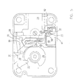
- the seal breaking action or resetting action is a result of the pivoting of the solenoid reset lever 34 about latch pivot 31.
- the solenoid reset lever 34 is spring biased by spring 50 in a clockwise direction about latch pivot 31. The force exerted by the spring 50 is less than the residual magnetic attraction force on armature plate 44 and, therefore, the spring 50 will not reset solenoid reset lever 34 whenever the armature plate 44 is magnetically sealed to the solenoid 40.
- the latch notch 33 is formed with sides parallel to each other and parallel to latch 32 at that portion resident in latch notch 33 when latched.
- solenoid reset cam follower 38 will be forced in a clockwise direction together with the remainder of the solenoid reset lever 34 about latch pivot 31 by solenoid reset cam 36 on slide 28.
- the latch input tab 46 is rotated clockwise about latch pivot 31 and forces the armature 42, generally to the left as viewed in Fig. 4, displacing armature plate 44 to a distance sufficient that the residual magnetic attraction in solenoid 40 is ineffective to re-attract armature plate 44 to a sealed position against solenoid housing 41.
- solenoid reset lever 34 As solenoid reset lever 34 is rotated by the solenoid reset cam 36 acting on the solenoid reset cam follower 38, the force exerted by solenoid reset lever 34 against the latch 32 is relieved, hence permitting spring 50 to urge latch member 32 clockwise around latch pivot 31 and further to engage latch 32 with side surface 62 of slide 28.
- latch 32 is positioned for re-engagement or latching engagement with the notch 33 upon the restoration of slide 28 to its raised or retracted position.
- cam wheel 26 is illustrated as rotated counter-clockwise to the point where a portion thereof engages nose portion 22 of bolt lever 16.
- bolt lever 16 has been displaced generally leftward and, in so translating, has withdrawn bolt 14 to its unlocked position.
- tenon 20 engages cam surface 66 on slide 28.
- Cam surface 66 serves to raise or restore slide 28 to its raised position as a result of the movement of opening bolt lever 16 or withdrawing bolt 14.
- latch 32 slips from the side surface 62 of slide 28 to be positioned in line with latch notch 33. Latch 32 is urged into the relocked or latched position by spring 50.
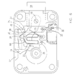
- cam 26 when rotated in a clockwise direction, will engage nose portion 22 of bolt lever 16 and will force bolt lever 16 upward against lever boss 52. Thereafter, the continued clockwise rotation of cam wheel 26 forces bolt lever 16 rightward with the top portion of bolt lever 16 riding against and following the underside of lever boss 52 until such time as the bolt lever 16 can clear lever boss 52. Having been placed in a position whereby latch 32 has been restored to its latching position engaged with latch notch 33, slide 28 is incapable of moving downward in response to engagement of tenon 20 with the sloped surface 68 of relock latch 70.
- Relock latch 70 is a portion of a serpentine spring 72, which is supported by and extends from support 27. As serpentine spring 72 will deflect under the force exerted thereon by tenon 20, the serpentine spring 72 permits the passage of the tenon 20 into slot 30 in slide 28. Once serpentine spring 72 has been deflected sufficiently to the right to pass tenon 20 into slot 30, the exerted forces of the serpentine spring 72, and more specifically, the sloped surface 68 thereof together with the force exerted by the cam wheel 26 on nose portion 22 will tend to move the bolt lever 16 in a clockwise direction about its pivot connection 18.
- Relock latch 70 and support 27 share an interface 25 oriented at an angle to relieve movement of relock latch 70 relative to support 27 in a restoring direction and to block movement of relock latch 70 in the opposite direction.
- cam 26 exerting further restore forces on nose portion 22 of bolt lever 16, effectively raising tenon 20 into the slot 30 of slide 28.
- the serpentine spring 72 has restored to its undeflected position thereby positioning relock latch 70 under tenon 20 and effectively blocking any downward or leftward movement of tenon 20 which would be necessary for bolt lever 16 to clear lever boss 52 of lock casing 12.
- FIG. 8 there is shown therein a schematic diagram of the electronic portions of the lock 10.
- Generator 80 is operated by dial 82 which is connected by a shaft 84, connecting generator 80 and cam wheel 26. Rotation of dial 82 operates the generator 80 to provide an output of generated electrical power to power conditioning circuits 86. Power conditioning circuits 86, in turn, provide power in the form of a DC voltage to the electronic controls 88.
- the dial 82 and cam wheel 26 may be interconnected and there maybe a separate drive path 92 between dial 82 and generator 80.
- the electronic controls 88 can receive a combination from an operator through keypad 90 or other input means, such as magnet cards, electronic keys or dial input, and subsequently the electronic controls 88 compare the combination with an authorized combination. In the event that the entered combination and the authorized combination compare equal, the electronic controls 88 then output a signal to operate the solenoid 40.
- the solenoid 40 must be pulsed at a time when the bolt lever 16, engaged with the high dwell 48 of cam wheel 26, is in its raised position. This is necessary in order to relieve the loading of slide 28 on latch 32 and relieve the forces on latch 32. If the lock 10 is to operate so that the position of the high dwell 48 can be other than engaged with nose position 22 at the time the lock 10 is ready to be opened, an electrical timing circuit is necessary to cause the energization of solenoid 40 whenever the slide 28 is raised or retracted to free latch 32.
- this invention provides several advantages over prior solenoid operated electronically controlled locks.
- the most significant of the advantages is that operation of the solenoid 40 requires only a very short pulse of current provided from a capacitor to pick the solenoid 40 once the combination is properly entered into the lock 10.
- a second advantageous feature of this device is that the solenoid 40 will remain in its actuated condition, thus eliminating the need for continued current flow to the solenoid 40 during the period of time necessary to physically open the lock 10 and withdraw the bolt 14.
- a further advantage of this system is that the slide mechanism restores to its latched position very early in the lock cycle and ensures that once the bolt lever 16 is restored to its locked position, neither can it be dislodged nor the bolt 14 reopened by forcing the bolt 14 itself.
Landscapes
- Physics & Mathematics (AREA)
- Electromagnetism (AREA)
- General Physics & Mathematics (AREA)
- Lock And Its Accessories (AREA)
Applications Claiming Priority (2)
| Application Number | Priority Date | Filing Date | Title |
|---|---|---|---|
| US852854 | 1992-03-17 | ||
| US08/852,854 US5893283A (en) | 1997-05-07 | 1997-05-07 | Solenoid controlled bolt control for an electronic lock |
Publications (2)
| Publication Number | Publication Date |
|---|---|
| EP0882860A2 true EP0882860A2 (de) | 1998-12-09 |
| EP0882860A3 EP0882860A3 (de) | 2000-09-13 |
Family
ID=25314399
Family Applications (1)
| Application Number | Title | Priority Date | Filing Date |
|---|---|---|---|
| EP19980303570 Withdrawn EP0882860A3 (de) | 1997-05-07 | 1998-05-07 | Solenoidaktivierte Riegelsteuerung für ein elektronisches Schloss |
Country Status (6)
| Country | Link |
|---|---|
| US (1) | US5893283A (de) |
| EP (1) | EP0882860A3 (de) |
| JP (1) | JPH1144135A (de) |
| KR (1) | KR19980086936A (de) |
| CN (1) | CN1200427A (de) |
| CA (1) | CA2236392A1 (de) |
Cited By (2)
| Publication number | Priority date | Publication date | Assignee | Title |
|---|---|---|---|---|
| CN101748938A (zh) * | 2010-02-08 | 2010-06-23 | 王建明 | 一种机械电子复合锁中的电子锁 |
| WO2013007990A1 (en) * | 2011-07-08 | 2013-01-17 | Terry Park | Lock and method of operation of a lock |
Families Citing this family (46)
| Publication number | Priority date | Publication date | Assignee | Title |
|---|---|---|---|---|
| US6006561A (en) * | 1997-05-07 | 1999-12-28 | Mas-Hamilton Group, Inc. | Electronic reset for solenoid activated control in an electronic lock |
| US6098433A (en) * | 1998-04-02 | 2000-08-08 | American Security Products Company | Lock for safes and other security devices |
| US6094953A (en) * | 1998-11-10 | 2000-08-01 | Mas-Hamilton Group, Inc. | Electrically controlled slidebolt lock |
| EP1069264B1 (de) * | 1999-07-12 | 2006-04-05 | Kaba AG | Motorisiertes Sicherheitsschloss |
| US6380787B1 (en) * | 1999-08-31 | 2002-04-30 | Micron Technology, Inc. | Integrated circuit and method for minimizing clock skews |
| US6401501B1 (en) | 2000-05-01 | 2002-06-11 | Master Lock Company | Lock construction |
| USD437204S1 (en) | 2000-05-01 | 2001-02-06 | Master Lock Company | Lock construction |
| CN2516662Y (zh) * | 2001-07-10 | 2002-10-16 | 张大鹏 | 遥控阴极锁 |
| AU2002343442A1 (en) * | 2001-09-26 | 2003-04-07 | Randy L. Squier | Lock assembly having secure engagement plate |
| WO2003089742A2 (en) * | 2002-04-14 | 2003-10-30 | Southco, Inc. | Electromechanical keeper |
| CA2522038A1 (en) * | 2003-04-11 | 2004-10-28 | Strattec Security Corporation | Ignition apparatus and method |
| US7355305B2 (en) * | 2003-12-08 | 2008-04-08 | Shen-Etsu Chemical Co., Ltd. | Small-size direct-acting actuator |
| US20060005592A1 (en) * | 2004-07-07 | 2006-01-12 | Moon Charles W | Manipulation-resistant combination lock |
| US20060226942A1 (en) * | 2005-03-30 | 2006-10-12 | Dimig Steven J | Residual magnetic devices and methods |
| US20060238285A1 (en) * | 2005-03-30 | 2006-10-26 | Dimig Steven J | Residual magnetic devices and methods |
| US20060219499A1 (en) * | 2005-03-30 | 2006-10-05 | Organek Gregory J | Residual magnetic devices and methods |
| US20060219513A1 (en) * | 2005-03-30 | 2006-10-05 | Organek Gregory J | Residual magnetic devices and methods |
| US8403124B2 (en) | 2005-03-30 | 2013-03-26 | Strattec Security Corporation | Residual magnetic devices and methods |
| US20060219497A1 (en) * | 2005-03-30 | 2006-10-05 | Organek Gregory J | Residual magnetic devices and methods |
| US20060238284A1 (en) * | 2005-03-30 | 2006-10-26 | Dimig Steven J | Residual magnetic devices and methods |
| US20060226941A1 (en) * | 2005-03-30 | 2006-10-12 | Dimig Steven J | Residual magnetic devices and methods |
| US7401483B2 (en) * | 2005-03-30 | 2008-07-22 | Strattec Security Corporation | Residual magnetic devices and methods for an ignition actuation blockage device |
| US20060219496A1 (en) * | 2005-03-30 | 2006-10-05 | Dimig Steven J | Residual magnetic devices and methods |
| US20060237959A1 (en) * | 2005-03-30 | 2006-10-26 | Dimig Steven J | Residual magnetic devices and methods |
| US7969705B2 (en) * | 2005-03-30 | 2011-06-28 | Strattec Security Corporation | Residual magnetic devices and methods |
| US20060219498A1 (en) * | 2005-03-30 | 2006-10-05 | Organek Gregory J | Residual magnetic devices and methods |
| KR100656277B1 (ko) * | 2005-10-07 | 2006-12-11 | 서울통신기술 주식회사 | 자기 발전식 도어락 시스템 |
| FR2893056B1 (fr) * | 2005-11-04 | 2009-11-13 | Mondelin Roger Sas | Dispositif support de porte plaques de materiau pour appareil de levage et de manutention |
| US20080211239A1 (en) * | 2007-03-02 | 2008-09-04 | Jon Edward Keller | Security improvement to solenoid-releasable mortise lockset having thumb-lever actuators |
| US8026781B2 (en) * | 2007-08-21 | 2011-09-27 | Anthony Freakes | Solenoid device with stable activation |
| US20090226050A1 (en) * | 2008-03-06 | 2009-09-10 | Hughes Michael L | System and apparatus for securing an item using a biometric lock |
| CN102134939A (zh) * | 2010-01-21 | 2011-07-27 | 郭保宣 | 电子开锁装置 |
| DE102010053154A1 (de) * | 2010-11-26 | 2012-05-31 | Assa Abloy Sicherheitstechnik Gmbh | Bewegungssperre für ein Sperrelement oder einen Aktuator in einem Schließsystem |
| US8443639B2 (en) * | 2010-12-08 | 2013-05-21 | Michael J. Walsh & Associates, Inc. | Resistant mechanical combination lock and improvements thereto |
| US8667821B2 (en) | 2010-12-08 | 2014-03-11 | Michael J. Walsh & Associates, Inc. | Resistant mechanical combination lock and improvements thereto |
| CN102071838B (zh) * | 2010-12-24 | 2012-10-03 | 陈浩 | 一种自供电的智能锁 |
| WO2014100115A2 (en) * | 2012-12-19 | 2014-06-26 | Lock Ii, Llc | Device and methods for preventing unwanted access to a locked enclosure |
| TWI604119B (zh) * | 2013-03-15 | 2017-11-01 | 薩爾金特製造公司 | 擷取鎖控制器脈衝的電子電路 |
| CN103993786B (zh) * | 2014-04-29 | 2016-05-18 | 南京东屋电气有限公司 | 一种电子机械双控锁 |
| WO2016109281A1 (en) | 2014-12-29 | 2016-07-07 | Invue Security Products Inc. | Merchandise display security systems and methods |
| EP3256671A4 (de) * | 2015-02-09 | 2018-10-10 | MG Tech Center BV h.o.d.n. Lock Technology | Elektronisches und mechanisches kombinationsschloss |
| US10253528B1 (en) * | 2018-02-21 | 2019-04-09 | Axtuator OY | Digital lock |
| US11187008B2 (en) * | 2018-04-18 | 2021-11-30 | Assa Abloy Korea | Clutch engagement assembly of door lock and driving device thereof |
| US12018516B2 (en) | 2021-06-30 | 2024-06-25 | Delta Cycle Corporation | Electronic lock |
| US12024924B2 (en) | 2021-07-01 | 2024-07-02 | Delta Cycle Corporation | Electronic lock |
| US12060733B2 (en) | 2021-08-16 | 2024-08-13 | Delta Cycle Corporation | Bicycle cable lock |
Citations (2)
| Publication number | Priority date | Publication date | Assignee | Title |
|---|---|---|---|---|
| US4831851A (en) | 1986-04-10 | 1989-05-23 | Supra Products, Inc. | Combination/electronic lock system |
| US5307656A (en) | 1990-12-17 | 1994-05-03 | La Gard, Inc. | High security electronic dial combination lock |
Family Cites Families (10)
| Publication number | Priority date | Publication date | Assignee | Title |
|---|---|---|---|---|
| GB815654A (en) * | 1956-05-04 | 1959-07-01 | Chubb & Sons Lock & Safe Co | Improvements in and relating to permutation locks |
| US2575674A (en) * | 1949-03-26 | 1951-11-20 | Harry C Miller | Permutation lock |
| US2658374A (en) * | 1950-03-02 | 1953-11-10 | Diebold Inc | Combination lock |
| US4745784A (en) * | 1986-04-21 | 1988-05-24 | Alan Uyeda | Electronic dial combination lock |
| US4910981A (en) * | 1989-03-17 | 1990-03-27 | Gartner Klaus W | Automatically locking and tumbler scrambling manipulation proof lock |
| JPH06229155A (ja) * | 1992-01-13 | 1994-08-16 | C & M Technology Inc | セキュリティロック機構 |
| US5592838A (en) * | 1992-02-20 | 1997-01-14 | Mas-Hamilton Group | Anti-attack interlocks for a combination lock mechanism |
| DE4323493C1 (de) * | 1993-07-14 | 1994-10-27 | Kromer Theodor Gmbh & Co Kg | Zahlenkombinationsschloß mit einem Drehknopf, mit einer Nockenscheibe und mit einem Einfallhebel |
| CA2174937A1 (en) * | 1993-10-29 | 1995-05-04 | Michael R. Clark | Electronic combination lock |
| US5632170A (en) * | 1995-12-20 | 1997-05-27 | Ilco Unican Corporation | Combination lock preventing manipulation for unauthorized access |
-
1997
- 1997-05-07 US US08/852,854 patent/US5893283A/en not_active Expired - Lifetime
-
1998
- 1998-04-29 CA CA 2236392 patent/CA2236392A1/en not_active Abandoned
- 1998-05-07 CN CN98102113A patent/CN1200427A/zh active Pending
- 1998-05-07 KR KR1019980016841A patent/KR19980086936A/ko not_active Withdrawn
- 1998-05-07 JP JP14049398A patent/JPH1144135A/ja not_active Withdrawn
- 1998-05-07 EP EP19980303570 patent/EP0882860A3/de not_active Withdrawn
Patent Citations (2)
| Publication number | Priority date | Publication date | Assignee | Title |
|---|---|---|---|---|
| US4831851A (en) | 1986-04-10 | 1989-05-23 | Supra Products, Inc. | Combination/electronic lock system |
| US5307656A (en) | 1990-12-17 | 1994-05-03 | La Gard, Inc. | High security electronic dial combination lock |
Cited By (5)
| Publication number | Priority date | Publication date | Assignee | Title |
|---|---|---|---|---|
| CN101748938A (zh) * | 2010-02-08 | 2010-06-23 | 王建明 | 一种机械电子复合锁中的电子锁 |
| CN101748938B (zh) * | 2010-02-08 | 2012-11-28 | 王建明 | 一种机械电子复合锁中的电子锁 |
| WO2013007990A1 (en) * | 2011-07-08 | 2013-01-17 | Terry Park | Lock and method of operation of a lock |
| GB2507898A (en) * | 2011-07-08 | 2014-05-14 | Terence Edward Park | Lock and method of operation of a lock |
| GB2507898B (en) * | 2011-07-08 | 2017-11-22 | Terence Edward Park | Combination lock with additional locking means |
Also Published As
| Publication number | Publication date |
|---|---|
| CN1200427A (zh) | 1998-12-02 |
| US5893283A (en) | 1999-04-13 |
| KR19980086936A (ko) | 1998-12-05 |
| JPH1144135A (ja) | 1999-02-16 |
| CA2236392A1 (en) | 1998-11-07 |
| EP0882860A3 (de) | 2000-09-13 |
Similar Documents
| Publication | Publication Date | Title |
|---|---|---|
| US5893283A (en) | Solenoid controlled bolt control for an electronic lock | |
| US6178791B1 (en) | Electronic reset for solenoid activated control in an electronic lock | |
| US4656850A (en) | Electric lock | |
| US7963574B2 (en) | Fail safe/fail secure lock with quick change access window | |
| US9797165B2 (en) | Electric latch retraction bar | |
| US7698918B2 (en) | Interchangeable lock operable in fail safe or fail secure modes | |
| US5681070A (en) | Locking mechanism | |
| US6094953A (en) | Electrically controlled slidebolt lock | |
| US7614669B2 (en) | Interchangeable lock operable in fail safe or fail secure modes | |
| US4918957A (en) | Lock with locking function released by insertion of a coded card | |
| EP0260860B1 (de) | Schliesseinrichtung | |
| US5878612A (en) | Electromagnetically actuated lock | |
| EP0333821B1 (de) | Elektrisch betätigbares türschloss | |
| EP0125813A2 (de) | Verschlussmechanismus | |
| GB2155535A (en) | Motor vehicle door lock | |
| HK1015430A (en) | Solenoid controlled bolt control for an electronic lock | |
| GB2123078A (en) | Electrically lockable fastening | |
| EP0107973B1 (de) | Sicherheitsvorrichtung für einen Schlossriegel | |
| HK1012200A (en) | Electronic reset for solenoid activated control in an electronic lock | |
| CN210118010U (zh) | 一种电开式门锁 | |
| CN210598508U (zh) | 一种小型掉电锁具 | |
| FI111748B (fi) | Elektroninen lukko | |
| GB2085956A (en) | Electromagnetic fastening | |
| RU2019656C1 (ru) | Замок | |
| EP4687167A1 (de) | Intelligenter kontaktorverriegelungsblock |
Legal Events
| Date | Code | Title | Description |
|---|---|---|---|
| PUAI | Public reference made under article 153(3) epc to a published international application that has entered the european phase |
Free format text: ORIGINAL CODE: 0009012 |
|
| AK | Designated contracting states |
Kind code of ref document: A2 Designated state(s): CH DE FR GB IT LI |
|
| AX | Request for extension of the european patent |
Free format text: AL;LT;LV;MK;RO;SI |
|
| PUAL | Search report despatched |
Free format text: ORIGINAL CODE: 0009013 |
|
| AK | Designated contracting states |
Kind code of ref document: A3 Designated state(s): AT BE CH CY DE DK ES FI FR GB GR IE IT LI LU MC NL PT SE |
|
| AX | Request for extension of the european patent |
Free format text: AL;LT;LV;MK;RO;SI |
|
| 17P | Request for examination filed |
Effective date: 20010313 |
|
| AKX | Designation fees paid |
Free format text: CH DE FR GB IT LI |
|
| RAP1 | Party data changed (applicant data changed or rights of an application transferred) |
Owner name: KABA MAS CORPORATION |
|
| 17Q | First examination report despatched |
Effective date: 20031031 |
|
| STAA | Information on the status of an ep patent application or granted ep patent |
Free format text: STATUS: THE APPLICATION IS DEEMED TO BE WITHDRAWN |
|
| 18D | Application deemed to be withdrawn |
Effective date: 20050601 |
|
| REG | Reference to a national code |
Ref country code: HK Ref legal event code: WD Ref document number: 1015430 Country of ref document: HK |