EP0880672B1 - Capacitive gap measurement device - Google Patents
Capacitive gap measurement device Download PDFInfo
- Publication number
- EP0880672B1 EP0880672B1 EP97903454A EP97903454A EP0880672B1 EP 0880672 B1 EP0880672 B1 EP 0880672B1 EP 97903454 A EP97903454 A EP 97903454A EP 97903454 A EP97903454 A EP 97903454A EP 0880672 B1 EP0880672 B1 EP 0880672B1
- Authority
- EP
- European Patent Office
- Prior art keywords
- electrode
- shield
- insulation
- probe
- layer
- Prior art date
- Legal status (The legal status is an assumption and is not a legal conclusion. Google has not performed a legal analysis and makes no representation as to the accuracy of the status listed.)
- Expired - Lifetime
Links
- 238000005259 measurement Methods 0.000 title description 9
- 238000009413 insulation Methods 0.000 claims description 38
- 239000000919 ceramic Substances 0.000 claims description 24
- 238000000151 deposition Methods 0.000 claims description 23
- 229910052751 metal Inorganic materials 0.000 claims description 21
- 239000002184 metal Substances 0.000 claims description 21
- 230000008021 deposition Effects 0.000 claims description 14
- 238000000034 method Methods 0.000 claims description 14
- 239000007787 solid Substances 0.000 claims description 5
- 150000004767 nitrides Chemical class 0.000 claims description 4
- 238000001771 vacuum deposition Methods 0.000 claims description 4
- 229910052752 metalloid Inorganic materials 0.000 claims description 2
- 150000002738 metalloids Chemical class 0.000 claims description 2
- 238000004544 sputter deposition Methods 0.000 claims description 2
- 238000005229 chemical vapour deposition Methods 0.000 claims 1
- 239000000523 sample Substances 0.000 description 65
- 239000010410 layer Substances 0.000 description 34
- 238000004519 manufacturing process Methods 0.000 description 6
- 230000008901 benefit Effects 0.000 description 5
- 239000000463 material Substances 0.000 description 5
- 229910000831 Steel Inorganic materials 0.000 description 4
- 238000003754 machining Methods 0.000 description 4
- BASFCYQUMIYNBI-UHFFFAOYSA-N platinum Chemical compound [Pt] BASFCYQUMIYNBI-UHFFFAOYSA-N 0.000 description 4
- 239000010959 steel Substances 0.000 description 4
- 239000004020 conductor Substances 0.000 description 3
- 239000007789 gas Substances 0.000 description 3
- 230000008569 process Effects 0.000 description 3
- 230000008878 coupling Effects 0.000 description 2
- 238000010168 coupling process Methods 0.000 description 2
- 238000005859 coupling reaction Methods 0.000 description 2
- 229910052809 inorganic oxide Inorganic materials 0.000 description 2
- 238000009434 installation Methods 0.000 description 2
- 229910052741 iridium Inorganic materials 0.000 description 2
- GKOZUEZYRPOHIO-UHFFFAOYSA-N iridium atom Chemical compound [Ir] GKOZUEZYRPOHIO-UHFFFAOYSA-N 0.000 description 2
- 230000004048 modification Effects 0.000 description 2
- 238000012986 modification Methods 0.000 description 2
- 238000012856 packing Methods 0.000 description 2
- 229910052697 platinum Inorganic materials 0.000 description 2
- 230000035945 sensitivity Effects 0.000 description 2
- 238000010008 shearing Methods 0.000 description 2
- 229910017083 AlN Inorganic materials 0.000 description 1
- PIGFYZPCRLYGLF-UHFFFAOYSA-N Aluminum nitride Chemical compound [Al]#N PIGFYZPCRLYGLF-UHFFFAOYSA-N 0.000 description 1
- XUIMIQQOPSSXEZ-UHFFFAOYSA-N Silicon Chemical compound [Si] XUIMIQQOPSSXEZ-UHFFFAOYSA-N 0.000 description 1
- BOTDANWDWHJENH-UHFFFAOYSA-N Tetraethyl orthosilicate Chemical compound CCO[Si](OCC)(OCC)OCC BOTDANWDWHJENH-UHFFFAOYSA-N 0.000 description 1
- RTAQQCXQSZGOHL-UHFFFAOYSA-N Titanium Chemical compound [Ti] RTAQQCXQSZGOHL-UHFFFAOYSA-N 0.000 description 1
- 150000004703 alkoxides Chemical class 0.000 description 1
- 239000004411 aluminium Substances 0.000 description 1
- 229910052782 aluminium Inorganic materials 0.000 description 1
- XAGFODPZIPBFFR-UHFFFAOYSA-N aluminium Chemical compound [Al] XAGFODPZIPBFFR-UHFFFAOYSA-N 0.000 description 1
- QVGXLLKOCUKJST-UHFFFAOYSA-N atomic oxygen Chemical compound [O] QVGXLLKOCUKJST-UHFFFAOYSA-N 0.000 description 1
- YHWCPXVTRSHPNY-UHFFFAOYSA-N butan-1-olate;titanium(4+) Chemical compound [Ti+4].CCCC[O-].CCCC[O-].CCCC[O-].CCCC[O-] YHWCPXVTRSHPNY-UHFFFAOYSA-N 0.000 description 1
- 239000011248 coating agent Substances 0.000 description 1
- 238000000576 coating method Methods 0.000 description 1
- 239000002131 composite material Substances 0.000 description 1
- 238000010292 electrical insulation Methods 0.000 description 1
- 239000012467 final product Substances 0.000 description 1
- 239000000446 fuel Substances 0.000 description 1
- 238000010438 heat treatment Methods 0.000 description 1
- 230000007062 hydrolysis Effects 0.000 description 1
- 238000006460 hydrolysis reaction Methods 0.000 description 1
- 230000006872 improvement Effects 0.000 description 1
- 230000005389 magnetism Effects 0.000 description 1
- 239000002905 metal composite material Substances 0.000 description 1
- 150000002739 metals Chemical class 0.000 description 1
- 229910003455 mixed metal oxide Inorganic materials 0.000 description 1
- 239000000203 mixture Substances 0.000 description 1
- 239000000075 oxide glass Substances 0.000 description 1
- 239000001301 oxygen Substances 0.000 description 1
- 229910052760 oxygen Inorganic materials 0.000 description 1
- 230000002093 peripheral effect Effects 0.000 description 1
- 238000000623 plasma-assisted chemical vapour deposition Methods 0.000 description 1
- 238000006068 polycondensation reaction Methods 0.000 description 1
- 239000000843 powder Substances 0.000 description 1
- 230000002035 prolonged effect Effects 0.000 description 1
- 239000010703 silicon Substances 0.000 description 1
- 229910052710 silicon Inorganic materials 0.000 description 1
- 239000002356 single layer Substances 0.000 description 1
- 238000003980 solgel method Methods 0.000 description 1
- 238000009987 spinning Methods 0.000 description 1
- 239000000758 substrate Substances 0.000 description 1
- 229910052715 tantalum Inorganic materials 0.000 description 1
- GUVRBAGPIYLISA-UHFFFAOYSA-N tantalum atom Chemical compound [Ta] GUVRBAGPIYLISA-UHFFFAOYSA-N 0.000 description 1
- 239000002470 thermal conductor Substances 0.000 description 1
- 239000010936 titanium Substances 0.000 description 1
- 229910052719 titanium Inorganic materials 0.000 description 1
- MYWQGROTKMBNKN-UHFFFAOYSA-N tributoxyalumane Chemical compound [Al+3].CCCC[O-].CCCC[O-].CCCC[O-] MYWQGROTKMBNKN-UHFFFAOYSA-N 0.000 description 1
Images
Classifications
-
- G—PHYSICS
- G01—MEASURING; TESTING
- G01B—MEASURING LENGTH, THICKNESS OR SIMILAR LINEAR DIMENSIONS; MEASURING ANGLES; MEASURING AREAS; MEASURING IRREGULARITIES OF SURFACES OR CONTOURS
- G01B7/00—Measuring arrangements characterised by the use of electric or magnetic techniques
- G01B7/14—Measuring arrangements characterised by the use of electric or magnetic techniques for measuring distance or clearance between spaced objects or spaced apertures
Definitions
- This invention relates to the measurement of gaps, and especially to the measurement of gaps in gas turbines, for example the measurement of gaps from a probe to a solid object such as a shaft, disc, or to an intermittent object such as a turbine blade or the like.
- US-A 3 706 919 discloses a capacitive distance sensor with an electrode, a surrounding shield, and insulation between electrode and shield , and around the shield.
- the insulation and shields are provided as separate assembly components.
- Such a probe typically will comprise an electrode that will couple capacitively with the turbine blade, a shield that is located between the electrode and the turbine casing, a probe body that surrounds the shield and enables the probe to fit precisely in the recess that is provided for it in the casing, and insulation provided between the electrode and shield and also between the shield and retainer in order to electrically isolate the electrode and shield from the casing.
- the electrode is connected to the centre conductor of a triaxial cable, and the shield to the intermediate screen of the cable while the retainer or the housing is connected to the outer screen of the cable which removes the signals from the probe from the vicinity of the turbine.
- the signal from the electrode is passed to the shield via a unity gain amplifier so that the electrode signal is screened from ground (the casing) by means of a buffered version of itself.
- Such a probe will function quite satisfactorily to enable a blade - casing gap to be maintained at about 1mm, but it is extremely expensive to manufacture:
- the probe will be expected to operate at a temperature in the order of 1000°C which means that the insulating elements must be manufactured from machined ceramics.
- the insulating elements which are in the form of rings, will have as small a wall thickness as possible in order to be able to maximise the size of the electrode (which increases the sensitivity of the probe), thereby increasing the difficulty and cost of manufacture.
- the assembly of the probes is a highly skilled operation which adds to the cost of the final product, especially since the probes must be installed in a turbine and tested at the normal operating temperature in of the turbine.
- a device for capacitively measuring the distance to an object which comprises an electrode that will couple capacitively with the object, a shield located about the electrode and electrically isolated from the electrode by means of insulation, and a layer of insulation that surrounds the shield, wherein the insulation between the electrode and the shield and the insulation that surrounds the shield are formed by deposition.
- the device according to the invention has the advantage of significantly reduced manufacturing cost due to the removal of two physical components (the ceramic insulating rings) that are difficult to machine, and their replacement by deposited layers which are simple and inexpensive to form.
- the insulation between the electrode and the shield, and the insulation surrounding the shield will be much thinner than the radial thickness of any preformed ceramic disc can be, the diameter of the electrode can be significantly increased for any given aperture size in an engine casing, thereby increasing the sensitivity of the device.
- the probe may, if desired, include a shield as a preformed part, in which case the insulation between the electrode and shield and the insulation between the shield and the casing may both be deposited on the shield.
- a shield as a preformed part, in which case the insulation between the electrode and shield and the insulation between the shield and the casing may both be deposited on the shield.
- Such a probe thus is formed solely by machining parts from metal (the electrode, the part(s) forming the shield and the body (if any)) rather than from ceramics.
- the insulation between the electrode and the shield may be deposited on the electrode instead of the shield.
- the shield itself may then be deposited on the insulation, and, if desired, the insulation between the shield and the housing may be formed on the shield by deposition.
- the shield is formed, it is preferred for it to enclose the electrode subltantially entirely with the exception of that part of the electrode that will couple capacitively with the object, in order to reduce or eliminate any capacitive coupling with any other elements such as an engine casing or the like.
- a probe body that is formed as a separate part may be provided if desired, or alternatively, it may also be formed on the insulation by deposition.
- This form of probe has the advantage that it can be formed as a single, monolithic, item, thereby not only removing the expensive machining operations for forming the ceramic insulation rings, but also removing the skilled assembly process of the probe.
- an additional advantage of this form of probe is that it will not be the subject of differential thermal expansion of its component parts in operation. If a conventional probe were to be used for turbine blade tip clearance measurement, differential thermal expansion of the metal and ceramic parts could cause them to become loose to some degree when the probe is heated up to the normal operating temperature of about 1000°C. Also, the difference in pressure on either side of the turbine blades as they pass the probe applies a vibrating force on the electrode at a frequency upto 6000 Hz or higher, normally from 1000 to 6000 Hz, which causes the probe electrode to apply a vibrating shearing force on the ceramic insulating rings. In some instances, for example with certain turbochargers, the vibrating force can have a frequency as high as 100 kHz.
- substantially the entire probe can be formed from the same material, thereby avoiding the problems of differential thermal expansion. Furthermore, by removing the ceramic rings, which are relatively poor thermal conductors, temperature differences over different regions of the probe can be reduced.
- the electrode may be formed from a solid body of metal, this has the disadvantage that its operating temperature is limited to the maximum operating temperature of the metal, for example, about 1125°C in the case of steel.
- the electrode is formed as a ceramic body, and the shield, together with the layers of insulation between the electrode and the shield and between the shield and the housing are formed by deposition.
- the electrode may be rendered conductive by having a layer of conductive material, for example metal, deposited on the ceramic, or alternatively, the ceramic body could be formed as a conductive ceramic/metal composite.
- a probe which contains no bulk metal parts can operate at significantly higher temperatures, for example up to 1200°C or higher, for example up to 1500°C or beyond.
- a stoichiometric probe that is to say, a probe that can be used in turbines in which fuel is burned in a stoichiometric quantity of oxygen in order to maximise the thermodynamic efficiency of the engine.
- the layers that are formed by deposition may be formed by any method that will generate a layer that has the necessary adhesion and thermal stability to enable it to operate at the relevant temperature, for example or 1000°C, 1200°C or 1500°C.
- the layers may, for example, be formed by deposition in the condensed phase, for instance by sol-gel methods, which involve the hydrolysis and polycondensation of a metal alkoxide, for example silicon tetraethoxide, titanium butoxide or aluminium butoxide to produce in inorganic oxide gel which is converted to an inorganic oxide glass by a low temperature heat treatment.
- the layers may be formed by other deposition techniques, for example by vacuum deposition methods such as plasma assisted chemical vapour deposition, by sputtering or, preferably, by plasma deposition, all of which processes are well known and commercially employed for a number of purposes.
- vacuum deposition methods such as plasma assisted chemical vapour deposition, by sputtering or, preferably, by plasma deposition, all of which processes are well known and commercially employed for a number of purposes.
- plasma deposition the component is spun in a vacuum while a ceramic or metal powder is sprayed through an arc or flame that flashes it into a plasma. As the plasma hits the cold spinning part, it condenses, forming a layer of ceramic or metal.
- Each layer of insulation or metal may be formed as a single layer only, or if desired may be built up from a number of layers.
- one or more keying layers may be provided in order to improve the adhesion between the top layer and the substrate, the keying layer(s) being formed, for example by a different vacuum deposition process and/or having a different stoichiometry from that of the top layer so that the properties of the layers are graded over the total thickness.
- the insulating layers that are deposited by these methods are generally oxides and nitrides of metals or metalloids, for example oxides and nitrides of aluminium, titanium, tantalum and silicon, or mixtures thereof with themselves or with other oxides or nitrides.
- the use of mixed metal oxides for the layers is also envisaged. It should be appreciated, however, that the invention, at least in its broadest aspect, is not limited to any particular deposition technique.
- a method of forming a device for capacitively measuring the distance of a turbine blade tip from the internal surface of a casing which comprises forming an electrode that will couple capacitively with the turbine blade, depositing a layer of insulation over at least that part of the electrode that will be located in the casing, depositing a layer of metal over the insulation to form a shield, and depositing a second layer of insulation over the shield.
- This method of manufacture of the device may be employed for forming any of the devices described above.
- the layers may be formed to any thickness that is appropriate to the function of the layer.
- a thickness of from 0.01 to 1 micrometres, preferably from 0.1 to 0.2 micrometres will be appropriate in order to provide the necessary electrical conductivity, while for the layers of electrical insulation, thicknesses of from 0.2 to 0.5 micrometres will be appropriate.
- that part of the electrode that faces the object (the "front face"), especially where the probe is intended to be used to measure turbine blade tip clearance, may be formed with a significantly greater thickness, for example with a thickness greater than 0.5 mm, preferably in the range of from 0.5 to 2mm, and especially from 0.75 to 1.5mm.
- Such a layer can be formed so that the layer is softer than the material forming the turbine blade, and so be abradable by the turbine blade, thereby ensuring a very small and controllable gap between the blade and the front face of the electrode.
- the probe could be manufactured in its entirety before installation in the casing, it is possible to form the probe without the front face of the electrode, to install the probe in the casing and only then to deposit the front face of the electrode. The front face of the electrode can then be machined back to the required level, leaving the probe flush with the inside of the casing. During operation of the engine, a blade tip could erode the casing liner and the front face of the probe, but still leave the probe operational.
- the device according to the invention can be used for gap measurement in general and can function at temperatures up to the limit of the materials from which it is formed. It can be employed anywhere in a gas turbine, steam turbine or other turbomachinery, reciprocating engine or other equipment requiring measurement of gap size.
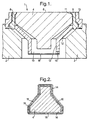
- figure 1 shows a gap measurement probe 1 for determining the position of the tip of a turbine blade (not shown) with respect to the turbine casing 2.
- the probe 1 comprises an electrode 4 formed from steel having a front face 6 that is directed toward the turbine and across which the tips of the turbine blades pass as the turbine rotates.
- the electrode 4 is located within a shield which comprises a bottom guard 8 and a top guard 10, each of which is also machined from steel.
- the bottom guard 8 has an internal lip 9 that engages a peripheral recess 11 in the electrode in order to ensure that the electrode cannot slide forward out of the bottom guard-8 toward the turbine blades
- the top guard 10 has a generally frusto-conical belled portion 12 and cylindrical portion 13, the belled portion 12 being capable of engaging the rear shoulder of the electrode 4 to prevent the electrode sliding backwards into the engine casing 2.
- a retainer 15 which seats the bottom guard 8, top guard 10 and electrode 4 correctly within a recess in the engine casing 2.
- the bottom guard 8 has been provided over its entire surface except for those parts thereof in contact with the top guard 10 with a 0.2mm thick layer of insulation formed from aluminium nitride by plasma deposition so that, when assembled, the metal forming the top guard will be electrically insulated from both the electrode 4 and the turbine casing 2.
- the top guard 10 is be similarly coated although it may be entirely separated from both the electrode 4 and the casing 2 by means of an air gap.
- the electrode 4 is connected to the centre conductor of a triaxial cable (not shown) by conventional means, while the screen formed by the top and bottom guards 8 and 10 are connected to the intermediate screen of the triaxial cable.
- the screen voltage is set to that of the electrode by means of a unity gain amplifier, so that it will prevent any capacitive coupling between the electrode and the turbine casing 2 which is at ground potential.
- the probe 1 is formed in a very simple and inexpensive manner, without the need to form any parts from ceramics by machining, and will be able to withstand any temperature up to the maximum working temperature of the steel parts thereof.
- the top guard 8 and the bottom guard 10 are slipped over opposite ends of the electrode 4 and butted together or otherwise engaged so that they enclose the electrode, and so that the electrode is firmly held between the two guards by means of the lip 9 in the bottom guard and the belled portion 12 of the top guard. Although clearances are shown between the various parts of the assembly, this is simply for the sake of clarity.
- the top guard 8 and bottom guard 10 are then welded together and a hole 16 is drilled through the cylindrical part 13 of the top guard 10 generally at a level of the end of the electrode to enable the triaxial cable to be inserted.
- the cable (not shown) is cut back and inserted through the hole and the central wire of the cable is brazed to the end face of the electrode and the intermediate screen is brazed to the top guard 10.
- the probe 1 is then dropped into the recess provided in the engine casing 2 and the retainer 15 is located around the electrode and top guard 8 and welded to the casing 2, thereby preventing the probe 1 from sliding out of the casing recess toward the turbine blades.
- the outer screen of the triaxial cable is welded to the engine casing 2, and a thin piece of shim stock 18 is spot welded over the end of the top guard 10 so that the entire electrode is surrounded by the shield formed by the top and bottom guards with the exception of the front face 6 thereof.
- a ceramic packing disc (not shown) is then placed over the end of the cylindrical portion of the top guard 10 and a metal disc (not shown) is positioned over the packing disc to close the recess in the casing 2, and is tack welded to the casing.
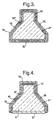
- Figure 2 shows schematically a similar form of capacitance probe to that shown in figure 1, but in which the electrode 4 has been provided with a first ceramic insulating layer 14 over its entire surface (including the front face), followed by a 0.3mm thick layer 16 of platinum/iridium (excluding the front face) which forms the shield, and finally a further 0.2mm thick layer 18 of ceramic which insulates the shield from the turbine casing 2.
- the probe corresponds to the assembly of the electrode 4, bottom guard 8 and top guard 10 shown in figure 1, and can be secured in a recess in the engine casing and operated exactly as the probe shown in figure 1.
- the probe has the advantage that only one element, the electrode 4, need be formed by machining, thereby reducing manufacturing costs.
- Figure 3 shows a modification of the probe shown in figure 2 in which the electrode 4 has an electrode body 4' formed from bulk ceramic, on which a platinum/iridium layer 4" has been deposited by plasma deposition.
- the insulation layers 14 and 18 and the shield 16 are formed on the electrode 4 as described above with reference to figure 2.
- This form of probe has the advantage that it contains no bulk metal parts. The only bulk parts are formed from a ceramic, and so it is possible for this probe to withstand significantly higher temperatures, for example in excess of 1200°C without failing.
- Figure 4 shows schematically an improvement of the probe shown in figure 3 in which the front face 6 of the electrode 4 is formed as a relatively thick coating of metal which has been deposited in the form of a relatively low density, porous metal layer or a metal/ceramic composite.
- the layer forming the front face has a thickness of about 1mm and is relatively soft (compared with the ceramic or the turbine blade), so that, after installation, the front surface of the electrode may be abraded by the turbine blades, thereby forming a small and controllable gap between the two.
Landscapes
- Physics & Mathematics (AREA)
- General Physics & Mathematics (AREA)
- Measurement Of Length, Angles, Or The Like Using Electric Or Magnetic Means (AREA)
Applications Claiming Priority (3)
| Application Number | Priority Date | Filing Date | Title |
|---|---|---|---|
| US615372 | 1996-02-14 | ||
| US08/615,372 US5760593A (en) | 1996-02-14 | 1996-02-14 | Gap measurement device |
| PCT/GB1997/000403 WO1997030326A1 (en) | 1996-02-14 | 1997-02-13 | Capacitive gap measurement device |
Publications (2)
| Publication Number | Publication Date |
|---|---|
| EP0880672A1 EP0880672A1 (en) | 1998-12-02 |
| EP0880672B1 true EP0880672B1 (en) | 2002-09-04 |
Family
ID=24465075
Family Applications (1)
| Application Number | Title | Priority Date | Filing Date |
|---|---|---|---|
| EP97903454A Expired - Lifetime EP0880672B1 (en) | 1996-02-14 | 1997-02-13 | Capacitive gap measurement device |
Country Status (7)
Cited By (1)
| Publication number | Priority date | Publication date | Assignee | Title |
|---|---|---|---|---|
| US12152915B2 (en) | 2018-12-12 | 2024-11-26 | Weston Aerospace Limited | Probe for monitoring a moving engine element |
Families Citing this family (25)
| Publication number | Priority date | Publication date | Assignee | Title |
|---|---|---|---|---|
| FR2750489B1 (fr) * | 1996-06-26 | 1998-08-28 | Philips Electronics Nv | Dispositif du type capteur capacitif composite |
| KR20010012125A (ko) * | 1997-04-28 | 2001-02-15 | 칼 하인쯔 호르닝어 | 증기 터빈용 열절연 장치 |
| FR2811422B1 (fr) | 2000-07-06 | 2002-08-30 | Snecma Moteurs | Capteur de mesure de jeux par abrasion multiprofondeur |
| US6400162B1 (en) * | 2000-07-21 | 2002-06-04 | Ade Corporation | Capacitive displacement sensor for measuring thin targets |
| US6575011B1 (en) | 2001-04-19 | 2003-06-10 | The United States Of America As Represented By The Secretary Of The Navy | Blade tip clearance probe and method for measuring blade tip clearance |
| US8151623B2 (en) | 2002-09-23 | 2012-04-10 | Siemens Energy, Inc. | Sensor for quantifying widening reduction wear on a surface |
| US7582359B2 (en) * | 2002-09-23 | 2009-09-01 | Siemens Energy, Inc. | Apparatus and method of monitoring operating parameters of a gas turbine |
| US7618712B2 (en) * | 2002-09-23 | 2009-11-17 | Siemens Energy, Inc. | Apparatus and method of detecting wear in an abradable coating system |
| GB2406381B (en) * | 2003-09-27 | 2005-10-12 | Future Technology | Sensors |
| US8742944B2 (en) * | 2004-06-21 | 2014-06-03 | Siemens Energy, Inc. | Apparatus and method of monitoring operating parameters of a gas turbine |
| US7511516B2 (en) * | 2006-06-13 | 2009-03-31 | General Electric Company | Methods and systems for monitoring the displacement of turbine blades |
| GB2449709A (en) * | 2007-06-02 | 2008-12-03 | Rolls Royce Plc | Method and apparatus for determining a clearance between relatively movable components |
| DE102008006833A1 (de) * | 2008-01-30 | 2009-08-06 | Mtu Aero Engines Gmbh | Sonde für eine kapazitive Sensoreinrichtung und Spaltmesssystem |
| US8344741B2 (en) * | 2008-10-16 | 2013-01-01 | General Electric Company | Systems, methods, and apparatus for monitoring clearance in a rotary machine |
| US8056606B2 (en) * | 2009-10-26 | 2011-11-15 | General Electric Company | Methods of making and using ceramic metallic interlocked components |
| US8571813B2 (en) * | 2010-03-16 | 2013-10-29 | Siemens Energy, Inc. | Fiber optic sensor system for detecting surface wear |
| EP2442077A1 (en) * | 2010-10-12 | 2012-04-18 | Future Technology (Sensors) Ltd | Sensor assemblies |
| US9279336B2 (en) * | 2012-09-05 | 2016-03-08 | United Technologies Corporation | High temperature split-face probe |
| US9417048B2 (en) | 2012-10-31 | 2016-08-16 | General Electric Company | Capacitive sensor device and method of manufacture |
| CN105982650B (zh) | 2015-03-04 | 2019-02-15 | 百略医学科技股份有限公司 | 红外线温度计 |
| GB2544751B (en) * | 2015-11-24 | 2017-11-22 | Future Tech (Sensors) Ltd | Multi-Layer Electrically Conductive Sensors |
| US10619998B2 (en) * | 2016-05-26 | 2020-04-14 | Rolls-Royce Corporation | Method of measuring clearance between rotating and static components |
| US10551220B2 (en) | 2016-06-27 | 2020-02-04 | Rolls-Royce Corporation | Capacitive measurement device |
| GB2566053A (en) | 2017-08-31 | 2019-03-06 | Weston Aerospace Ltd | Sensor and method of manufacturing same |
| US10641595B2 (en) * | 2018-04-09 | 2020-05-05 | United Technologies Corporation | Low profile triaxial blade tip clearance probe assembly with driven guard |
Family Cites Families (7)
| Publication number | Priority date | Publication date | Assignee | Title |
|---|---|---|---|---|
| US3706919A (en) * | 1970-08-17 | 1972-12-19 | Ade Corp | Capacitive gauge |
| JPS5735320A (en) * | 1980-08-11 | 1982-02-25 | Telmec Co Ltd | Structure of mask for baking of semiconductor integrated circuit |
| GB2131176B (en) * | 1982-10-07 | 1986-02-19 | Rolls Royce | Method of manufacturing a capacitance distance measuring probe |
| JPS6020552A (ja) * | 1983-07-14 | 1985-02-01 | Seiko Epson Corp | 半導体装置 |
| JPS6425555A (en) * | 1987-07-22 | 1989-01-27 | Matsushita Electronics Corp | Trench forming method |
| JPH0437106A (ja) * | 1990-06-01 | 1992-02-07 | Matsushita Electric Ind Co Ltd | 薄膜コンデンサ |
| DE69412769T2 (de) * | 1993-12-07 | 1999-01-14 | Matsushita Electric Industrial Co., Ltd., Kadoma, Osaka | Kapazitiver Sensor und Verfahren zur Herstellung |
-
1996
- 1996-02-14 US US08/615,372 patent/US5760593A/en not_active Expired - Lifetime
-
1997
- 1997-02-13 WO PCT/GB1997/000403 patent/WO1997030326A1/en active IP Right Grant
- 1997-02-13 JP JP52909697A patent/JP4173915B2/ja not_active Expired - Fee Related
- 1997-02-13 DE DE69715156T patent/DE69715156T2/de not_active Expired - Lifetime
- 1997-02-13 CA CA002244886A patent/CA2244886C/en not_active Expired - Fee Related
- 1997-02-13 AU AU18011/97A patent/AU1801197A/en not_active Abandoned
- 1997-02-13 EP EP97903454A patent/EP0880672B1/en not_active Expired - Lifetime
Cited By (1)
| Publication number | Priority date | Publication date | Assignee | Title |
|---|---|---|---|---|
| US12152915B2 (en) | 2018-12-12 | 2024-11-26 | Weston Aerospace Limited | Probe for monitoring a moving engine element |
Also Published As
| Publication number | Publication date |
|---|---|
| CA2244886C (en) | 2005-12-20 |
| CA2244886A1 (en) | 1997-08-21 |
| JP2000504836A (ja) | 2000-04-18 |
| EP0880672A1 (en) | 1998-12-02 |
| US5760593A (en) | 1998-06-02 |
| JP4173915B2 (ja) | 2008-10-29 |
| DE69715156D1 (de) | 2002-10-10 |
| WO1997030326A1 (en) | 1997-08-21 |
| DE69715156T2 (de) | 2003-04-17 |
| AU1801197A (en) | 1997-09-02 |
Similar Documents
| Publication | Publication Date | Title |
|---|---|---|
| EP0880672B1 (en) | Capacitive gap measurement device | |
| US5101165A (en) | Electrical capacitance clearanceometer | |
| US4804905A (en) | Capacitive measuring system for measuring the distance between two relatively movable parts | |
| CN102150031B (zh) | 监测部件磨损的设备和方法 | |
| US9291069B2 (en) | Instrument port seal for RF measurement | |
| US6717418B2 (en) | Method and apparatus for measuring turbine blade tip clearance | |
| EP2462418B1 (fr) | Capteur de pression capacitif integrant une mesure de temperature compatible avec les milieux chauds | |
| US6756908B2 (en) | Crack detection in fracture-critical machine parts | |
| EP2442077A1 (en) | Sensor assemblies | |
| US5973502A (en) | Capacitive sensor including a coaxial cable and a probe | |
| US8513960B2 (en) | Probe for a capacitive sensor device and gap-measuring system | |
| US10352738B2 (en) | Multi-layer electrically conductive sensor | |
| EP0596619A1 (en) | Diamond-coated article with integral wearout indicator | |
| CN100374814C (zh) | 用于对距一个物体的距离进行容性测量的传感器 | |
| US12152915B2 (en) | Probe for monitoring a moving engine element | |
| WO1997040340A1 (en) | Capacitive gap measurement device | |
| Sheard et al. | Gap Measurement Device | |
| CN120202365A (zh) | 滑动环密封装置的滑动环以及用于制造其的方法 |
Legal Events
| Date | Code | Title | Description |
|---|---|---|---|
| PUAI | Public reference made under article 153(3) epc to a published international application that has entered the european phase |
Free format text: ORIGINAL CODE: 0009012 |
|
| 17P | Request for examination filed |
Effective date: 19980708 |
|
| AK | Designated contracting states |
Kind code of ref document: A1 Designated state(s): BE CH DE FR GB IT LI NL SE |
|
| GRAG | Despatch of communication of intention to grant |
Free format text: ORIGINAL CODE: EPIDOS AGRA |
|
| 17Q | First examination report despatched |
Effective date: 20011031 |
|
| RAP1 | Party data changed (applicant data changed or rights of an application transferred) |
Owner name: BICC GENERAL PYROTENAX CABLES LIMITED |
|
| GRAG | Despatch of communication of intention to grant |
Free format text: ORIGINAL CODE: EPIDOS AGRA |
|
| GRAH | Despatch of communication of intention to grant a patent |
Free format text: ORIGINAL CODE: EPIDOS IGRA |
|
| GRAH | Despatch of communication of intention to grant a patent |
Free format text: ORIGINAL CODE: EPIDOS IGRA |
|
| RAP1 | Party data changed (applicant data changed or rights of an application transferred) |
Owner name: TYCO THERMAL CONTROLS UK LIMITED |
|
| GRAA | (expected) grant |
Free format text: ORIGINAL CODE: 0009210 |
|
| AK | Designated contracting states |
Kind code of ref document: B1 Designated state(s): BE CH DE FR GB IT LI NL SE |
|
| PG25 | Lapsed in a contracting state [announced via postgrant information from national office to epo] |
Ref country code: NL Free format text: LAPSE BECAUSE OF FAILURE TO SUBMIT A TRANSLATION OF THE DESCRIPTION OR TO PAY THE FEE WITHIN THE PRESCRIBED TIME-LIMIT Effective date: 20020904 Ref country code: LI Free format text: LAPSE BECAUSE OF FAILURE TO SUBMIT A TRANSLATION OF THE DESCRIPTION OR TO PAY THE FEE WITHIN THE PRESCRIBED TIME-LIMIT Effective date: 20020904 Ref country code: FR Free format text: LAPSE BECAUSE OF NON-PAYMENT OF DUE FEES Effective date: 20020904 Ref country code: CH Free format text: LAPSE BECAUSE OF FAILURE TO SUBMIT A TRANSLATION OF THE DESCRIPTION OR TO PAY THE FEE WITHIN THE PRESCRIBED TIME-LIMIT Effective date: 20020904 Ref country code: BE Free format text: LAPSE BECAUSE OF FAILURE TO SUBMIT A TRANSLATION OF THE DESCRIPTION OR TO PAY THE FEE WITHIN THE PRESCRIBED TIME-LIMIT Effective date: 20020904 |
|
| REG | Reference to a national code |
Ref country code: GB Ref legal event code: FG4D |
|
| REG | Reference to a national code |
Ref country code: CH Ref legal event code: EP |
|
| REF | Corresponds to: |
Ref document number: 69715156 Country of ref document: DE Date of ref document: 20021010 |
|
| PGFP | Annual fee paid to national office [announced via postgrant information from national office to epo] |
Ref country code: FR Payment date: 20030117 Year of fee payment: 7 |
|
| NLV1 | Nl: lapsed or annulled due to failure to fulfill the requirements of art. 29p and 29m of the patents act | ||
| PGFP | Annual fee paid to national office [announced via postgrant information from national office to epo] |
Ref country code: GB Payment date: 20030205 Year of fee payment: 7 |
|
| REG | Reference to a national code |
Ref country code: CH Ref legal event code: PL |
|
| EN | Fr: translation not filed | ||
| PLBE | No opposition filed within time limit |
Free format text: ORIGINAL CODE: 0009261 |
|
| STAA | Information on the status of an ep patent application or granted ep patent |
Free format text: STATUS: NO OPPOSITION FILED WITHIN TIME LIMIT |
|
| 26N | No opposition filed |
Effective date: 20030605 |
|
| PG25 | Lapsed in a contracting state [announced via postgrant information from national office to epo] |
Ref country code: GB Free format text: LAPSE BECAUSE OF NON-PAYMENT OF DUE FEES Effective date: 20040213 |
|
| GBPC | Gb: european patent ceased through non-payment of renewal fee |
Effective date: 20040213 |
|
| PGFP | Annual fee paid to national office [announced via postgrant information from national office to epo] |
Ref country code: IT Payment date: 20150225 Year of fee payment: 19 Ref country code: DE Payment date: 20150226 Year of fee payment: 19 |
|
| PGFP | Annual fee paid to national office [announced via postgrant information from national office to epo] |
Ref country code: SE Payment date: 20150226 Year of fee payment: 19 |
|
| REG | Reference to a national code |
Ref country code: DE Ref legal event code: R119 Ref document number: 69715156 Country of ref document: DE |
|
| REG | Reference to a national code |
Ref country code: SE Ref legal event code: EUG |
|
| PG25 | Lapsed in a contracting state [announced via postgrant information from national office to epo] |
Ref country code: SE Free format text: LAPSE BECAUSE OF NON-PAYMENT OF DUE FEES Effective date: 20160214 |
|
| PG25 | Lapsed in a contracting state [announced via postgrant information from national office to epo] |
Ref country code: IT Free format text: LAPSE BECAUSE OF NON-PAYMENT OF DUE FEES Effective date: 20160213 |
|
| PG25 | Lapsed in a contracting state [announced via postgrant information from national office to epo] |
Ref country code: DE Free format text: LAPSE BECAUSE OF NON-PAYMENT OF DUE FEES Effective date: 20160901 |