EP0879488B1 - Rundstrahlantenne - Google Patents
Rundstrahlantenne Download PDFInfo
- Publication number
- EP0879488B1 EP0879488B1 EP97902464A EP97902464A EP0879488B1 EP 0879488 B1 EP0879488 B1 EP 0879488B1 EP 97902464 A EP97902464 A EP 97902464A EP 97902464 A EP97902464 A EP 97902464A EP 0879488 B1 EP0879488 B1 EP 0879488B1
- Authority
- EP
- European Patent Office
- Prior art keywords
- radiation
- gaussian
- laguerre
- reflector
- intensity distribution
- Prior art date
- Legal status (The legal status is an assumption and is not a legal conclusion. Google has not performed a legal analysis and makes no representation as to the accuracy of the status listed.)
- Expired - Lifetime
Links
Images


Classifications
-
- H—ELECTRICITY
- H01—ELECTRIC ELEMENTS
- H01Q—ANTENNAS, i.e. RADIO AERIALS
- H01Q19/00—Combinations of primary active antenna elements and units with secondary devices, e.g. with quasi-optical devices, for giving the antenna a desired directional characteristic
- H01Q19/10—Combinations of primary active antenna elements and units with secondary devices, e.g. with quasi-optical devices, for giving the antenna a desired directional characteristic using reflecting surfaces
- H01Q19/102—Combinations of primary active antenna elements and units with secondary devices, e.g. with quasi-optical devices, for giving the antenna a desired directional characteristic using reflecting surfaces wherein the surfaces are of convex toroïdal shape
-
- H—ELECTRICITY
- H01—ELECTRIC ELEMENTS
- H01Q—ANTENNAS, i.e. RADIO AERIALS
- H01Q19/00—Combinations of primary active antenna elements and units with secondary devices, e.g. with quasi-optical devices, for giving the antenna a desired directional characteristic
- H01Q19/10—Combinations of primary active antenna elements and units with secondary devices, e.g. with quasi-optical devices, for giving the antenna a desired directional characteristic using reflecting surfaces
Definitions
- the present invention concerns an antenna for radiofrequency (r.f.) transmission.
- a beam having a fundamental Hermite-Gaussian radial intensity to illuminate a cone which reflects the radiation over 360° in azimuth has its maximum intensity illuminating the point of the cone and this causes scattering and interference which, in turn, causes high sidelobes and a ragged elevation pattern.
- Such a design is also difficult to model accurately.
- a method of transmitting radiofrequency radiation over an azimuth angle of substantially 360° which is characterised by illuminating a substantially conical reflector with a beam having a Laguerre-Gaussian intensity distribution, the minimum of the Laguerre-Gaussian distribution coinciding with the apex of the reflector, and the arrangement of the beam and relector being such that the radiation reflected from the reflector is divergent,
- substantially conical when used in this specification, is intended to be construed in a broad sense where, in addition to the case of a perfect cone within the strictest meaning, other cases where reflection over 360° in azimuth is provided are included. Such cases would include structures based on a cone shape but with sides which arc convex or concave.
- an radiofrequency antenna for providing transmission over substantially 360° in azimuth comprises a conical reflector and means for illuminating said reflector with a beam having a Laguerre-Gaussian intensity distribution, the minimum of the Laguerre-Gaussian distribution coinciding with the apex of the reflector, and the arrangement of the beam and the reflector being such that the radiation reflected from the reflector is divergent.
- a further preferred embodiment includes a source of radiation having a Fundamental Hermite-Gaussian intensity distribution and means for converting said radiation to radiation having a Laguerre-Gaussian intensity distribution.
- the means for converting radiation having a Fundamental Hermite-Gaussian intensity distribution may comprise a spiral phaseplate.
- a further preferred embodiment includes means for collimating the radiation having a Fundamental Hermite-Gaussian intensity distribution.
- the means for collimating the radiation having a Fundamental Hermite-Gaussian intensity distribution may comprise at least one lens.
- a further preferred embodiment includes means for controlling the angular coverage in elevation of the output radiation of the antenna.
- the means for controlling the angular coverage in elevation of the output radiation of the antenna may comprise at least one lens.
- the radiation having a Fundamental Hermite-Gaussian intensity distribution is linearly polarised.
- a further preferred embodiment includes means for converting said linearly polarised radiation to circularly polarised radiation.
- the means for converting said linearly polarised radiation to circularly polarised radiation may comprise a quarter wave plate.
- radiation having a Fundamental Hermite-Gaussian intensity distribution has a local maximum in intensity at the centre of the beam.
- Such radiation is converted to radiation having a Laguerre-Gaussian intensity distribution (figure 1b) on passing through a spiral phaseplate as will be described later.
- the latter radiation has a local minimum in intensity at its centre. (The value of intensity at this local minimum is zero, thus defining a null).
- Linearly polarised radiation having a Fundamental Hermite-Gaussian intensity distribution is supplied via a corrugated feedhorn 3. This radiation is diverging until it reaches collimating lens 4.
- the collimated radiation passes through quarter wave plate 5 which converts it to circularly polarised radiation.
- the circularly polarised radiation then passes through spiral phaseplate 6 which converts its intensity distribution to a Laguerre-Gaussian mode.
- the radiation then passes through lens 7 to illuminate conical reflector 8 which reflects the radiation over substantially 360°.
- the Laguerre-Gaussian radiation has a null at the centre of the beam which is coincident with the point of the conical reflector. Thus scattering is avoided.
- the axis 9 of the antenna is vertical so that the reflection of radiation over 360° gives rise to an antenna with a transmission azimuth of that angle.
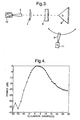
- the nominal elevation angle A of the transmission i.e. the angle of the maximum intensity of the transmitted radiation
- the choice of lens 7 determines the spread X of the transmitted elevation.
- the radiation source 10 was an InP Gunn oscillator.
- the output was coupled from the WG27 waveguide (not shown) of the oscillator into free space through a corrugated scalar feedhorn 3 which produced a vertically polarised fundamental Hermite-Gaussian mode beam with a beam waist of 4.2mm.
- the free space beam was collimated with an 88mm diameter, high density polyethylene (HDPE) planar-convex lens 4, which had an input focal length of 100mm and an output focal length of 320mm.
- HDPE high density polyethylene
- the fundamental Hermite-Gaussian mode beam was converted to a second order Laguerre-Gaussian mode beam using a spiral phaseplate 6 machined from HDPE.
- the phaseplate had a diameter of 88mm and a step height of 13.4mm.
- the spiral phaseplate was located 360mm from the planar surface of lens 4.
- the Laguerre-Gaussian mode beam fell incident on an aluminium conical reflector 8, located 720mm from the planar surface of lens 4.
- the cone had a diameter of 100mm and a half-angle of 47 degrees.
- the reflected power was collected using a Boonton 4220 power meter 11 having a WG27 sensor head (not shown), which was swept in an arc through the horizontal plane, pivoting about a point 25mm behind the apex of the cone.
- the power sensor was fitted with another corrugated scalar feedhom 3 similar to that used on the oscillator. The distance from the pivot point to the feedhorn beamwaist was 250mm.
- the angular coverage is relatively narrow since the beam was not focused down onto the tip of the cone. Doing so would give a more divergent beam and consequently a greater angular spread in elevation.
- conical reflectors are used in the examples illustrated, other reflector shapes, which provide reflection over 360° in azimuth may be used. Such variations might include a convex variation on the cone shape (figure 5a) or a concave variation (figure 5b).
- Laguerre-Gaussian ( LG ) modes like Hermite-Gaussian (HG ) modes, form a complete basis set for paraxial light beams.
- the former exhibit circular symmetry, the latter rectangular.
- Two indices identify a given mode, and the modes are normally denoted LG l / p and HG mn .
- m and n are the numbers of nodes in the x and y directions respectively.
- l is the number of 2 ⁇ cycles in phase around the circumference and (p+ 1) the number of radial nodes.
- the amplitude, u l / p of the LG l / p mode in cylindrical co-ordinates is u l p ( r , ⁇ , z ) ⁇ e - ikr 2 /2 R e - r 2 / w 2 e - i (2 p + l +1) ⁇ e - il ⁇ (-1) p ( r 2 / w ) l L l p (2 r 2 / w 2 ), where R is the wavefront radius of curvature, w is the radius for which the Gaussian term falls to 1/ e of its on-axis value, ⁇ is the Gouy phase and L l / p ( x ) a generalised Laguerre polynomial.
- the azimuthal phase term, e il ⁇ distinguishes the Laguerre-Gaussian modes from the Hermite-Gaussian modes.
- This phase term creates helical wavefronts for the Laguerre-Gaussian modes in contrast to the planar wavefronts of the Hermite-Gaussian modes (see J.M. Vaughan and D.V. Willetts, Optics Comm. 30 (1979) 263).
- Angular momentum is associated with these helical wavefronts which is termed orbital angular momentum and is distinguished from the spin angular momentum associated with the polarisation state. It has been shown that a pure Laguerre-Gaussian beam has an orbital angular momentum equivalent to lh per photon (See L. Allen, M.W. Beijersbergen, R. J. C. Spreeuw and J. P. Woerdman, Phys. Rev. A 45 (1992) 8185).
- Laguerre-Gaussian laser beams may be produced directly (M. Harris, C.A. Hill and J.M. Vaughan, Optics Comm. 106 (1994) 161), or by the conversion of Hermite-Gaussian modes.
- three different classes of mode converter have been demonstrated. Two of these, spiral phaseplates (M.W. Beijersbergen, R.P.C. Coerwinkel, M. Kristensen and J.P Woerdman, Optics Comm. 112 (1994) 321) and computer generated holographic converter (N. R. Heckenberg, R McDuff, C. P. Smith and A. C.
- the other class of converter is the cylindrical-lens mode converter (M.W. Beijersbergen, L. Allen H.E.L.O. van der Veen and J.P. Woerdman, Optics Comm. 96 (1993) 123) which converts higher order Hermite-Gaussian modes to the corresponding Laguerre-Gaussian mode. Unlike the spiral phaseplate and the holographic converter, this method can produce pure Laguerre-Gaussian modes.
- the orbital angular momentum in the beam is equivalent to l h per photon. Consequently, for a fixed power, the angular momentum in the beam is proportional to the wavelength; unlike linear momentum, h / ⁇ per photon, where for a fixed power the linear momentum in the beam is wavelength independent.
- the total angular momentum, J z of a Laguerre-Gaussian beam is the sum of orbital and spin angular momenta (L. Allen, M.W. Beijersbergen, RJ.C. Spreeuw and J.P. Woerdman, Phys. Rev. A 45 (1992) 8185.
- J z l ⁇ 1.
- the Hermite-Gaussian mode converted in this work has a well-defined linear polarisation and consequently the total angular momentum in the beam is due entirely to orbital angular momentum.
- the spiral phaseplate (Fig. 6) has one planar surface (not shown) and one spiral surface 12.
- the spiral surface 12 forms one period of a helix, with a step discontinuity.
- an incident ray 13 gives rise to a refracted ray 14 where the angle of refraction is ⁇ .
- the total phase delay around the phaseplate must be an integer multiple of 2 ⁇ , i.e. 2 ⁇ l .
- the phase of the beam is discontinuous at the step and this is observed as a break in the ring intensity pattern.
- Beijersbergen et al. have modelled the detuning of the step height through the transition from one Laguerre-Gaussian mode to another (M.W. Beijersbergen, R.P.C. Coerwinkel, M. Kristensen and J.P Woerdman, Optics Comm. 112 (1994) 321).
- the converter only changes the phase and not the intensity of the beam.
- the annular intensity pattern arises from the far field diffraction of the beam's screw dislocation.
- the beam produced is not a pure mode, but an infinite superposition of Laguerre-Gaussian modes.
- the conversion from the HG 00 to the LG 1 / 0 mode was calculated to be 78% efficient.
- n 2 sin( ⁇ + ⁇ ) n 1 sin ⁇
- Figure 7 shows equation (12) plotted as a function of radius for different values of n 1 / n 2 .
- the angular momentum per photon has units of l h and the radius is in units of l ⁇ .
- L has no value at very small values of r / l ⁇ . Just below the critical angle, L has a maximum value which falls rapidly to unity as r / l ⁇ increases. For our case, where n 1 / n 2 ⁇ 1.5, the small-angle approximation is valid when r > l ⁇ .
- Figure 8 shows an experimental configuration used to produce millimetre wave, free-space, Laguerre-Gaussian modes.
- the source 10 was an InP Gunn diode oscillator with a peak output power of 10-20mW. Adjusting the dimensions of the resonant cavity tuned the linearly polarised output from 72 to 95GHz (G.M. Smith, TEO's at mm-wave frequencies and their characterisation using quasioptical techniques. Ph.D. Thesis, St Andrews (1990)).
- a circular-aperture, corrugated feed-horn 3 produced a ⁇ 98% pure HG 00 beam with Rayleigh range of 50mm (R.J.Wylde, Proc IEE, part H, 13 (1984) 258).
- a polyethylene lens 4 of focal length 120mm collimated the beam with w ⁇ 25mm.
- the phaseplate 6 was also made of polyethylene, which has a refractive index of 1.52 at millimetre-wave frequencies (J C G Lesurf, Millimetre-wave Optics, Devices and Systems (Adam Hilger /IOP, 1990)). Two different phaseplates were used, one to generate the LG 1 / 0 mode and the other to generate the LG 2 / 0 mode.
- the step heights were 6.7mm and 13.4mm respectively to give a single and a double wavelength step at 86GHz.
- the planar surface of the phaseplate and both surfaces of the collimating lens were cut with an antireflection texture of quarter-wavelength deep concentric grooves.
- An aluminium mirror 12 reflected the output from the phaseplate onto a detector 11 mounted on an x-y scanning stage 13 placed in the far field of the converter.
- the detector 11 used was an Anritsu MP81B/ML83A with an identical feed horn 3 to that on the oscillator.
- the antenna pattern of the horn is Gaussian in form, and so the measured intensity profile is the convolution of the true far field diffraction pattern and a Gaussian point spread function.
- the x-y scanning stage and detector were computer controlled to measure a 50 x 50 grid over a square area with a side of 100mm. The readings were transferred to Mathematica (Wolfram Research, Inc., Mathematica, Version 2.2, Champaign, Illinois, USA (1994)), in which they were interpolated and displayed as density plots.
- Figure 9 (a) shows the result of the conversion from HG 00 to LG 1 / 0.
- the central minimum a characteristic of the Laguerre-Gaussian mode
- Figure 9(b) shows the corresponding result for the LG 2 / 0 mode.
- the radius of maximum intensity of the LG 2 / 0 is 2 times that of the LG 1 / 0 (M.J. Padgett and L. Allen, "The Poynting vector in Laguerre-Gaussian laser modes", Optics Comm. (in press)).
- the linear polarisation state of the Laguerre-Gaussian beams was demonstrated using a wire-grid polariser, with which the beam could be completely attenuated.
Landscapes
- Aerials With Secondary Devices (AREA)
- Details Of Aerials (AREA)
- Variable-Direction Aerials And Aerial Arrays (AREA)
- Surgical Instruments (AREA)
- Developing Agents For Electrophotography (AREA)
Claims (11)
- Verfahren zur Übertragung von Hochfrequenzstrahlung über einen Azimutwinkel von im Wesentlichen 360°,
dadurch gekennzeichnet, dass
ein im Wesentlichen konischer Reflektor mit einem Strahl mit einer Laguerre-Gaußschen Intensitätsverteilung bestrahlt wird, wobei das Minimum der Laguerre-Gaußschen Intensitätsverteilung mit dem Scheitel des Reflektors zusammenfällt und die Anordnung des Strahls und des Reflektors so ist, dass die vom Reflektor reflektierte Strahlung divergent ist. - Hochfrequenzantenne, die eine Übertragung über einen Azimutwinkel von im Wesentlichen 360° ermöglicht, mit einem konischen Reflektor und einer Einrichtung zum Bestrahlen des Reflektors mit einem Strahl mit einer Laguerre-Gaußschen Intensitätsverteilung, wobei das Minimum der Laguerre-Gaußschen Intensitätsverteilung mit dem Scheitel des Reflektors zusammenfällt und die Anordnung des Strahls und des Reflektors so ist, dass die vom Reflektor reflektierte Strahlung divergent ist.
- Hochfrequenzantenne nach Anspruch 2, die ferner eine Strahlungsquelle mit einer Fundamentalen Hermite-Gaußschen Intensitätsverteilung und eine Einrichtung aufweist, die diese Strahlung in eine Strahlung mit Laguerre-Gaußscher Intensitätsverteilung umwandelt.
- Hochfrequenzantenne nach Anspruch 3, wobei die Einrichtung zur Umwandlung der Strahlung mit Fundamental Hermite-Gaußscher Intensitätsverteilung ein Spiral-Phasenplättchen aufweist.
- Hochfrequenzantenne nach Anspruch 4, die ferner eine Einrichtung zur Kollimation der Strahlung aufweist.
- Hochfrequenzantenne nach Anspruch 5, wobei die Einrichtung zur Kollimation der Strahlung mit einer Fundamental Hermite-Gaußschen Intensitätsverteilung mindestens eine Linse aufweist.
- Hochfrequenzantenne nach Anspruch 6, die ferner eine Einrichtung zur Steuerung des Elevationswinkelbereichs der Abstrahlung der Hochfrequenzantenne aufweist.
- Hochfrequenzantenne nach Anspruch 7, wobei die Einrichtung zur Steuerung des Elevationswinkelbereichs der Abstrahlung der Hochfrequenzantenne mindestens eine Linse aufweist.
- Hochfrequenzantenne nach Anspruch 8, wobei die Strahlung mit Fundamentaler Hermite-Gaußscher Intensitätsverteilung linear polarisiert ist.
- Hochfrequenzantenne nach Anspruch 9, die ferner eine Einrichtung zur Umwandlung der linear polarisierten Strahlung in zirkular polarisierte Strahlung aufweist.
- Hochfrequenzantenne nach Anspruch 10, wobei die Einrichtung zur Umwandlung der linear polarisierten Strahlung in zirkular polarisierte Strahlung ein Lambda-Viertel-Plättchen enthält.
Applications Claiming Priority (3)
| Application Number | Priority Date | Filing Date | Title |
|---|---|---|---|
| GBGB9602395.7A GB9602395D0 (en) | 1996-02-06 | 1996-02-06 | Omnidirectional antenna |
| GB9602395 | 1996-02-06 | ||
| PCT/GB1997/000311 WO1997029525A1 (en) | 1996-02-06 | 1997-02-05 | Omnidirectional antenna |
Publications (2)
| Publication Number | Publication Date |
|---|---|
| EP0879488A1 EP0879488A1 (de) | 1998-11-25 |
| EP0879488B1 true EP0879488B1 (de) | 2003-06-18 |
Family
ID=10788214
Family Applications (1)
| Application Number | Title | Priority Date | Filing Date |
|---|---|---|---|
| EP97902464A Expired - Lifetime EP0879488B1 (de) | 1996-02-06 | 1997-02-05 | Rundstrahlantenne |
Country Status (10)
| Country | Link |
|---|---|
| US (1) | US6084552A (de) |
| EP (1) | EP0879488B1 (de) |
| KR (1) | KR19990082324A (de) |
| AT (1) | ATE243372T1 (de) |
| AU (1) | AU1610597A (de) |
| CA (1) | CA2245658C (de) |
| DE (1) | DE69722916T2 (de) |
| ES (1) | ES2196298T3 (de) |
| GB (2) | GB9602395D0 (de) |
| WO (1) | WO1997029525A1 (de) |
Families Citing this family (23)
| Publication number | Priority date | Publication date | Assignee | Title |
|---|---|---|---|---|
| US6201246B1 (en) * | 1998-07-31 | 2001-03-13 | Infocus Corporation | Non-imaging optical concentrator for use in infrared remote control systems |
| WO2000030212A1 (en) * | 1998-11-12 | 2000-05-25 | Bae Systems Electronics Limited | Scanning of electromagnetic beams |
| GB9907317D0 (en) * | 1999-03-31 | 1999-05-26 | Univ St Andrews | Antenna system |
| FR2793073B1 (fr) * | 1999-04-30 | 2003-04-11 | France Telecom | Antenne a reflecteur continu pour reception multiple de faisceaux de satellite |
| US6542304B2 (en) | 1999-05-17 | 2003-04-01 | Toolz, Ltd. | Laser beam device with apertured reflective element |
| US7307701B2 (en) * | 2003-10-30 | 2007-12-11 | Raytheon Company | Method and apparatus for detecting a moving projectile |
| US7151509B2 (en) * | 2003-12-24 | 2006-12-19 | The Boeing Company | Apparatus for use in providing wireless communication and method for use and deployment of such apparatus |
| GB2409559A (en) * | 2003-12-24 | 2005-06-29 | Peter Frost-Gaskin | Fire alarm with separately powered smoke and heat detectors |
| US6943742B2 (en) * | 2004-02-16 | 2005-09-13 | The Boeing Company | Focal plane array for THz imager and associated methods |
| US7382743B1 (en) | 2004-08-06 | 2008-06-03 | Lockheed Martin Corporation | Multiple-beam antenna system using hybrid frequency-reuse scheme |
| JP2006086184A (ja) * | 2004-09-14 | 2006-03-30 | Fuji Photo Film Co Ltd | レーザダイオード |
| US7463207B1 (en) | 2004-10-29 | 2008-12-09 | Lockheed Martin Corporation | High-efficiency horns for an antenna system |
| US8164533B1 (en) | 2004-10-29 | 2012-04-24 | Lockhead Martin Corporation | Horn antenna and system for transmitting and/or receiving radio frequency signals in multiple frequency bands |
| US7528778B1 (en) * | 2006-02-03 | 2009-05-05 | Hrl Laboratories, Llc | Structure for coupling power |
| US7675958B2 (en) * | 2006-08-02 | 2010-03-09 | Raytheon Company | Intra-cavity non-degenerate laguerre mode generator |
| US7737904B2 (en) * | 2008-06-11 | 2010-06-15 | Lockheed Martin Corporation | Antenna systems for multiple frequency bands |
| US20150138657A1 (en) * | 2013-11-21 | 2015-05-21 | Electronics And Telecommunications Research Institute | Antenna apparatus |
| US9267877B2 (en) | 2014-03-12 | 2016-02-23 | Nxgen Partners Ip, Llc | System and method for making concentration measurements within a sample material using orbital angular momentum |
| US9413448B2 (en) * | 2014-08-08 | 2016-08-09 | Nxgen Partners Ip, Llc | Systems and methods for focusing beams with mode division multiplexing |
| WO2018071808A1 (en) | 2016-10-14 | 2018-04-19 | Searete Llc | Wireless power transfer in the fresnel zone with a dynamic metasurface antenna |
| KR20180121372A (ko) * | 2017-04-28 | 2018-11-07 | 엘에스엠트론 주식회사 | 차량용 안테나 장치 |
| KR102656096B1 (ko) | 2019-06-14 | 2024-04-11 | 삼성전자주식회사 | 안테나 모듈을 포함하는 전자 장치 |
| CN113889771B (zh) * | 2021-09-10 | 2023-03-28 | 中国人民解放军空军工程大学 | 双圆极化多波束数字编码透射超构表面 |
Family Cites Families (7)
| Publication number | Priority date | Publication date | Assignee | Title |
|---|---|---|---|---|
| US2045398A (en) * | 1934-08-09 | 1936-06-23 | Massey Andrew | Radio antenna |
| DE1616252C3 (de) * | 1968-02-23 | 1978-11-02 | Allgemeine Elektricitaets-Gesellschaft Aeg-Telefunken, 1000 Berlin Und 6000 Frankfurt | Breitband-Rundstrahlantenne für Mikrowellen, bestehend aus einem vertikalen Rundhohlleiter und wenigstens einem Kegelreflektor |
| US4111564A (en) * | 1973-02-08 | 1978-09-05 | Trice Jr James R | Reference plane production |
| US4581529A (en) * | 1983-08-15 | 1986-04-08 | At&T Bell Laboratories | Read/write system for optical disc apparatus with fiber optics |
| JPS63240202A (ja) * | 1987-03-27 | 1988-10-05 | Nec Corp | 無指向性アンテナ |
| DE4001781C1 (de) * | 1990-01-23 | 1991-02-21 | Schott Glaswerke, 6500 Mainz, De | |
| US5486838A (en) * | 1993-08-23 | 1996-01-23 | Andrew Corporation | Broadband omnidirectional microwave antenna for minimizing radiation toward the upper hemisphere |
-
1996
- 1996-02-06 GB GBGB9602395.7A patent/GB9602395D0/en active Pending
-
1997
- 1997-02-05 GB GB9815874A patent/GB2324659B/en not_active Expired - Fee Related
- 1997-02-05 ES ES97902464T patent/ES2196298T3/es not_active Expired - Lifetime
- 1997-02-05 AU AU16105/97A patent/AU1610597A/en not_active Abandoned
- 1997-02-05 DE DE69722916T patent/DE69722916T2/de not_active Expired - Fee Related
- 1997-02-05 CA CA002245658A patent/CA2245658C/en not_active Expired - Fee Related
- 1997-02-05 WO PCT/GB1997/000311 patent/WO1997029525A1/en not_active Ceased
- 1997-02-05 US US09/117,268 patent/US6084552A/en not_active Expired - Fee Related
- 1997-02-05 EP EP97902464A patent/EP0879488B1/de not_active Expired - Lifetime
- 1997-02-05 AT AT97902464T patent/ATE243372T1/de not_active IP Right Cessation
- 1997-02-05 KR KR1019980706054A patent/KR19990082324A/ko not_active Ceased
Also Published As
| Publication number | Publication date |
|---|---|
| WO1997029525A1 (en) | 1997-08-14 |
| ATE243372T1 (de) | 2003-07-15 |
| AU1610597A (en) | 1997-08-28 |
| DE69722916T2 (de) | 2004-05-13 |
| GB2324659B (en) | 1999-12-29 |
| US6084552A (en) | 2000-07-04 |
| GB9815874D0 (en) | 1998-09-16 |
| CA2245658C (en) | 2003-07-22 |
| EP0879488A1 (de) | 1998-11-25 |
| DE69722916D1 (de) | 2003-07-24 |
| ES2196298T3 (es) | 2003-12-16 |
| KR19990082324A (ko) | 1999-11-25 |
| GB2324659A (en) | 1998-10-28 |
| GB9602395D0 (en) | 1996-04-03 |
| CA2245658A1 (en) | 1997-08-14 |
Similar Documents
| Publication | Publication Date | Title |
|---|---|---|
| EP0879488B1 (de) | Rundstrahlantenne | |
| Turnbull et al. | The generation of free-space Laguerre-Gaussian modes at millimetre-wave frequencies by use of a spiral phaseplate | |
| US4488156A (en) | Geodesic dome-lens antenna | |
| Boriskin et al. | Aperture antennas for millimeter and sub-millimeter wave applications | |
| Denisov et al. | 110 GHz gyrotron with a built-in high-efficiency converter | |
| US6825814B2 (en) | Antenna | |
| Garrett et al. | Fresnel zone plate antennas at millimeter wavelengths | |
| US5115482A (en) | Optical apparatus for conversion of whispering-gallery modes into a free space gaussian like beam | |
| Navarro-Cia et al. | Beamforming by left-handed extraordinary transmission metamaterial bi-and plano-concave lens at millimeter-waves | |
| US4188632A (en) | Rear feed assemblies for aerials | |
| US5719470A (en) | Gyrotron capable of outputting a plurality of wave beams of electromagnetic waves | |
| Wiltse | Zone plate designs for terahertz frequencies | |
| Thomas | A review of the early developments of circular-aperture hybrid-mode corrugated horns | |
| Bilitos et al. | Metal-only reflecting Luneburg lens design for sub-THz applications | |
| US20260005443A1 (en) | Photonic nanojet antenna using a single-material dielectric element with circular symmetry | |
| US20230299495A1 (en) | Photonic nanojet antenna using a single-material dielectric element with circular symmetry | |
| Wiltse | Large-angle zone plate antennas | |
| Stallard et al. | MAGICTRAC, a novel method for conversion of whispering-gallery modes into a free-space Gaussian-like beam | |
| McEwan et al. | Design of elliptical and offset reflector antennas using Gaussian beam theory | |
| Wu et al. | Terahertz Non-diffracting Beam Metasurface Generator | |
| James et al. | Luneburg lens element for the SKA | |
| Cahill et al. | The quasi-optical design of the QUaD Telescope | |
| Lazarus | Ellipsoidal and hyperboloidal lens aperture functions for computation of Fraunhofer diffraction patterns | |
| Bowen | Astigmatism in tapered slot antennas | |
| Ulich | Optimum radio telescope geometry |
Legal Events
| Date | Code | Title | Description |
|---|---|---|---|
| PUAI | Public reference made under article 153(3) epc to a published international application that has entered the european phase |
Free format text: ORIGINAL CODE: 0009012 |
|
| 17P | Request for examination filed |
Effective date: 19980724 |
|
| AK | Designated contracting states |
Kind code of ref document: A1 Designated state(s): AT BE CH DE DK ES FI FR GB GR IE IT LI LU MC NL PT SE |
|
| 17Q | First examination report despatched |
Effective date: 19981221 |
|
| RAP1 | Party data changed (applicant data changed or rights of an application transferred) |
Owner name: QINETIQ LIMITED |
|
| GRAH | Despatch of communication of intention to grant a patent |
Free format text: ORIGINAL CODE: EPIDOS IGRA |
|
| GRAH | Despatch of communication of intention to grant a patent |
Free format text: ORIGINAL CODE: EPIDOS IGRA |
|
| GRAA | (expected) grant |
Free format text: ORIGINAL CODE: 0009210 |
|
| AK | Designated contracting states |
Designated state(s): AT BE CH DE DK ES FI FR GB GR IE IT LI LU MC NL PT SE |
|
| PG25 | Lapsed in a contracting state [announced via postgrant information from national office to epo] |
Ref country code: NL Free format text: LAPSE BECAUSE OF FAILURE TO SUBMIT A TRANSLATION OF THE DESCRIPTION OR TO PAY THE FEE WITHIN THE PRESCRIBED TIME-LIMIT Effective date: 20030618 Ref country code: LI Free format text: LAPSE BECAUSE OF FAILURE TO SUBMIT A TRANSLATION OF THE DESCRIPTION OR TO PAY THE FEE WITHIN THE PRESCRIBED TIME-LIMIT Effective date: 20030618 Ref country code: CH Free format text: LAPSE BECAUSE OF FAILURE TO SUBMIT A TRANSLATION OF THE DESCRIPTION OR TO PAY THE FEE WITHIN THE PRESCRIBED TIME-LIMIT Effective date: 20030618 Ref country code: BE Free format text: LAPSE BECAUSE OF FAILURE TO SUBMIT A TRANSLATION OF THE DESCRIPTION OR TO PAY THE FEE WITHIN THE PRESCRIBED TIME-LIMIT Effective date: 20030618 Ref country code: AT Free format text: LAPSE BECAUSE OF FAILURE TO SUBMIT A TRANSLATION OF THE DESCRIPTION OR TO PAY THE FEE WITHIN THE PRESCRIBED TIME-LIMIT Effective date: 20030618 |
|
| REG | Reference to a national code |
Ref country code: GB Ref legal event code: FG4D |
|
| REG | Reference to a national code |
Ref country code: CH Ref legal event code: EP |
|
| REG | Reference to a national code |
Ref country code: SE Ref legal event code: TRGR |
|
| REG | Reference to a national code |
Ref country code: IE Ref legal event code: FG4D |
|
| REF | Corresponds to: |
Ref document number: 69722916 Country of ref document: DE Date of ref document: 20030724 Kind code of ref document: P |
|
| PG25 | Lapsed in a contracting state [announced via postgrant information from national office to epo] |
Ref country code: PT Free format text: LAPSE BECAUSE OF FAILURE TO SUBMIT A TRANSLATION OF THE DESCRIPTION OR TO PAY THE FEE WITHIN THE PRESCRIBED TIME-LIMIT Effective date: 20030918 Ref country code: GR Free format text: LAPSE BECAUSE OF FAILURE TO SUBMIT A TRANSLATION OF THE DESCRIPTION OR TO PAY THE FEE WITHIN THE PRESCRIBED TIME-LIMIT Effective date: 20030918 Ref country code: DK Free format text: LAPSE BECAUSE OF FAILURE TO SUBMIT A TRANSLATION OF THE DESCRIPTION OR TO PAY THE FEE WITHIN THE PRESCRIBED TIME-LIMIT Effective date: 20030918 |
|
| ET | Fr: translation filed | ||
| NLV1 | Nl: lapsed or annulled due to failure to fulfill the requirements of art. 29p and 29m of the patents act | ||
| REG | Reference to a national code |
Ref country code: ES Ref legal event code: FG2A Ref document number: 2196298 Country of ref document: ES Kind code of ref document: T3 |
|
| REG | Reference to a national code |
Ref country code: CH Ref legal event code: PL |
|
| PG25 | Lapsed in a contracting state [announced via postgrant information from national office to epo] |
Ref country code: LU Free format text: LAPSE BECAUSE OF NON-PAYMENT OF DUE FEES Effective date: 20040205 Ref country code: IE Free format text: LAPSE BECAUSE OF NON-PAYMENT OF DUE FEES Effective date: 20040205 Ref country code: FI Free format text: LAPSE BECAUSE OF NON-PAYMENT OF DUE FEES Effective date: 20040205 |
|
| PG25 | Lapsed in a contracting state [announced via postgrant information from national office to epo] |
Ref country code: SE Free format text: LAPSE BECAUSE OF NON-PAYMENT OF DUE FEES Effective date: 20040206 Ref country code: ES Free format text: LAPSE BECAUSE OF NON-PAYMENT OF DUE FEES Effective date: 20040206 |
|
| PG25 | Lapsed in a contracting state [announced via postgrant information from national office to epo] |
Ref country code: MC Free format text: LAPSE BECAUSE OF NON-PAYMENT OF DUE FEES Effective date: 20040228 |
|
| ET1 | Fr: translation filed ** revision of the translation of the patent or the claims | ||
| PLBE | No opposition filed within time limit |
Free format text: ORIGINAL CODE: 0009261 |
|
| STAA | Information on the status of an ep patent application or granted ep patent |
Free format text: STATUS: NO OPPOSITION FILED WITHIN TIME LIMIT |
|
| 26N | No opposition filed |
Effective date: 20040319 |
|
| EUG | Se: european patent has lapsed | ||
| REG | Reference to a national code |
Ref country code: IE Ref legal event code: MM4A |
|
| PG25 | Lapsed in a contracting state [announced via postgrant information from national office to epo] |
Ref country code: IT Free format text: LAPSE BECAUSE OF NON-PAYMENT OF DUE FEES Effective date: 20050205 |
|
| REG | Reference to a national code |
Ref country code: ES Ref legal event code: FD2A Effective date: 20040206 |
|
| PGFP | Annual fee paid to national office [announced via postgrant information from national office to epo] |
Ref country code: DE Payment date: 20090219 Year of fee payment: 13 |
|
| PGFP | Annual fee paid to national office [announced via postgrant information from national office to epo] |
Ref country code: GB Payment date: 20090219 Year of fee payment: 13 |
|
| PGFP | Annual fee paid to national office [announced via postgrant information from national office to epo] |
Ref country code: FR Payment date: 20090213 Year of fee payment: 13 |
|
| GBPC | Gb: european patent ceased through non-payment of renewal fee |
Effective date: 20100205 |
|
| REG | Reference to a national code |
Ref country code: FR Ref legal event code: ST Effective date: 20101029 |
|
| PG25 | Lapsed in a contracting state [announced via postgrant information from national office to epo] |
Ref country code: FR Free format text: LAPSE BECAUSE OF NON-PAYMENT OF DUE FEES Effective date: 20100301 |
|
| PG25 | Lapsed in a contracting state [announced via postgrant information from national office to epo] |
Ref country code: DE Free format text: LAPSE BECAUSE OF NON-PAYMENT OF DUE FEES Effective date: 20100901 |
|
| PG25 | Lapsed in a contracting state [announced via postgrant information from national office to epo] |
Ref country code: GB Free format text: LAPSE BECAUSE OF NON-PAYMENT OF DUE FEES Effective date: 20100205 |