EP0878989A2 - Surface coated substrate with reduced heat transmission - Google Patents
Surface coated substrate with reduced heat transmission Download PDFInfo
- Publication number
- EP0878989A2 EP0878989A2 EP19980108464 EP98108464A EP0878989A2 EP 0878989 A2 EP0878989 A2 EP 0878989A2 EP 19980108464 EP19980108464 EP 19980108464 EP 98108464 A EP98108464 A EP 98108464A EP 0878989 A2 EP0878989 A2 EP 0878989A2
- Authority
- EP
- European Patent Office
- Prior art keywords
- paint
- layer
- touching
- warmth
- film
- Prior art date
- Legal status (The legal status is an assumption and is not a legal conclusion. Google has not performed a legal analysis and makes no representation as to the accuracy of the status listed.)
- Granted
Links
Images


Classifications
-
- B—PERFORMING OPERATIONS; TRANSPORTING
- B05—SPRAYING OR ATOMISING IN GENERAL; APPLYING FLUENT MATERIALS TO SURFACES, IN GENERAL
- B05D—PROCESSES FOR APPLYING FLUENT MATERIALS TO SURFACES, IN GENERAL
- B05D7/00—Processes, other than flocking, specially adapted for applying liquids or other fluent materials to particular surfaces or for applying particular liquids or other fluent materials
- B05D7/14—Processes, other than flocking, specially adapted for applying liquids or other fluent materials to particular surfaces or for applying particular liquids or other fluent materials to metal, e.g. car bodies
-
- C—CHEMISTRY; METALLURGY
- C09—DYES; PAINTS; POLISHES; NATURAL RESINS; ADHESIVES; COMPOSITIONS NOT OTHERWISE PROVIDED FOR; APPLICATIONS OF MATERIALS NOT OTHERWISE PROVIDED FOR
- C09D—COATING COMPOSITIONS, e.g. PAINTS, VARNISHES OR LACQUERS; FILLING PASTES; CHEMICAL PAINT OR INK REMOVERS; INKS; CORRECTING FLUIDS; WOODSTAINS; PASTES OR SOLIDS FOR COLOURING OR PRINTING; USE OF MATERIALS THEREFOR
- C09D7/00—Features of coating compositions, not provided for in group C09D5/00; Processes for incorporating ingredients in coating compositions
-
- Y—GENERAL TAGGING OF NEW TECHNOLOGICAL DEVELOPMENTS; GENERAL TAGGING OF CROSS-SECTIONAL TECHNOLOGIES SPANNING OVER SEVERAL SECTIONS OF THE IPC; TECHNICAL SUBJECTS COVERED BY FORMER USPC CROSS-REFERENCE ART COLLECTIONS [XRACs] AND DIGESTS
- Y10—TECHNICAL SUBJECTS COVERED BY FORMER USPC
- Y10T—TECHNICAL SUBJECTS COVERED BY FORMER US CLASSIFICATION
- Y10T428/00—Stock material or miscellaneous articles
- Y10T428/24—Structurally defined web or sheet [e.g., overall dimension, etc.]
- Y10T428/24355—Continuous and nonuniform or irregular surface on layer or component [e.g., roofing, etc.]
- Y10T428/24372—Particulate matter
-
- Y—GENERAL TAGGING OF NEW TECHNOLOGICAL DEVELOPMENTS; GENERAL TAGGING OF CROSS-SECTIONAL TECHNOLOGIES SPANNING OVER SEVERAL SECTIONS OF THE IPC; TECHNICAL SUBJECTS COVERED BY FORMER USPC CROSS-REFERENCE ART COLLECTIONS [XRACs] AND DIGESTS
- Y10—TECHNICAL SUBJECTS COVERED BY FORMER USPC
- Y10T—TECHNICAL SUBJECTS COVERED BY FORMER US CLASSIFICATION
- Y10T428/00—Stock material or miscellaneous articles
- Y10T428/24—Structurally defined web or sheet [e.g., overall dimension, etc.]
- Y10T428/24479—Structurally defined web or sheet [e.g., overall dimension, etc.] including variation in thickness
- Y10T428/24496—Foamed or cellular component
-
- Y—GENERAL TAGGING OF NEW TECHNOLOGICAL DEVELOPMENTS; GENERAL TAGGING OF CROSS-SECTIONAL TECHNOLOGIES SPANNING OVER SEVERAL SECTIONS OF THE IPC; TECHNICAL SUBJECTS COVERED BY FORMER USPC CROSS-REFERENCE ART COLLECTIONS [XRACs] AND DIGESTS
- Y10—TECHNICAL SUBJECTS COVERED BY FORMER USPC
- Y10T—TECHNICAL SUBJECTS COVERED BY FORMER US CLASSIFICATION
- Y10T428/00—Stock material or miscellaneous articles
- Y10T428/24—Structurally defined web or sheet [e.g., overall dimension, etc.]
- Y10T428/24479—Structurally defined web or sheet [e.g., overall dimension, etc.] including variation in thickness
- Y10T428/24521—Structurally defined web or sheet [e.g., overall dimension, etc.] including variation in thickness with component conforming to contour of nonplanar surface
-
- Y—GENERAL TAGGING OF NEW TECHNOLOGICAL DEVELOPMENTS; GENERAL TAGGING OF CROSS-SECTIONAL TECHNOLOGIES SPANNING OVER SEVERAL SECTIONS OF THE IPC; TECHNICAL SUBJECTS COVERED BY FORMER USPC CROSS-REFERENCE ART COLLECTIONS [XRACs] AND DIGESTS
- Y10—TECHNICAL SUBJECTS COVERED BY FORMER USPC
- Y10T—TECHNICAL SUBJECTS COVERED BY FORMER US CLASSIFICATION
- Y10T428/00—Stock material or miscellaneous articles
- Y10T428/24—Structurally defined web or sheet [e.g., overall dimension, etc.]
- Y10T428/24942—Structurally defined web or sheet [e.g., overall dimension, etc.] including components having same physical characteristic in differing degree
- Y10T428/24983—Hardness
-
- Y—GENERAL TAGGING OF NEW TECHNOLOGICAL DEVELOPMENTS; GENERAL TAGGING OF CROSS-SECTIONAL TECHNOLOGIES SPANNING OVER SEVERAL SECTIONS OF THE IPC; TECHNICAL SUBJECTS COVERED BY FORMER USPC CROSS-REFERENCE ART COLLECTIONS [XRACs] AND DIGESTS
- Y10—TECHNICAL SUBJECTS COVERED BY FORMER USPC
- Y10T—TECHNICAL SUBJECTS COVERED BY FORMER US CLASSIFICATION
- Y10T428/00—Stock material or miscellaneous articles
- Y10T428/249921—Web or sheet containing structurally defined element or component
- Y10T428/249953—Composite having voids in a component [e.g., porous, cellular, etc.]
- Y10T428/249976—Voids specified as closed
-
- Y—GENERAL TAGGING OF NEW TECHNOLOGICAL DEVELOPMENTS; GENERAL TAGGING OF CROSS-SECTIONAL TECHNOLOGIES SPANNING OVER SEVERAL SECTIONS OF THE IPC; TECHNICAL SUBJECTS COVERED BY FORMER USPC CROSS-REFERENCE ART COLLECTIONS [XRACs] AND DIGESTS
- Y10—TECHNICAL SUBJECTS COVERED BY FORMER USPC
- Y10T—TECHNICAL SUBJECTS COVERED BY FORMER US CLASSIFICATION
- Y10T428/00—Stock material or miscellaneous articles
- Y10T428/249921—Web or sheet containing structurally defined element or component
- Y10T428/249953—Composite having voids in a component [e.g., porous, cellular, etc.]
- Y10T428/249987—With nonvoid component of specified composition
- Y10T428/24999—Inorganic
-
- Y—GENERAL TAGGING OF NEW TECHNOLOGICAL DEVELOPMENTS; GENERAL TAGGING OF CROSS-SECTIONAL TECHNOLOGIES SPANNING OVER SEVERAL SECTIONS OF THE IPC; TECHNICAL SUBJECTS COVERED BY FORMER USPC CROSS-REFERENCE ART COLLECTIONS [XRACs] AND DIGESTS
- Y10—TECHNICAL SUBJECTS COVERED BY FORMER USPC
- Y10T—TECHNICAL SUBJECTS COVERED BY FORMER US CLASSIFICATION
- Y10T428/00—Stock material or miscellaneous articles
- Y10T428/25—Web or sheet containing structurally defined element or component and including a second component containing structurally defined particles
-
- Y—GENERAL TAGGING OF NEW TECHNOLOGICAL DEVELOPMENTS; GENERAL TAGGING OF CROSS-SECTIONAL TECHNOLOGIES SPANNING OVER SEVERAL SECTIONS OF THE IPC; TECHNICAL SUBJECTS COVERED BY FORMER USPC CROSS-REFERENCE ART COLLECTIONS [XRACs] AND DIGESTS
- Y10—TECHNICAL SUBJECTS COVERED BY FORMER USPC
- Y10T—TECHNICAL SUBJECTS COVERED BY FORMER US CLASSIFICATION
- Y10T428/00—Stock material or miscellaneous articles
- Y10T428/31504—Composite [nonstructural laminate]
- Y10T428/31678—Of metal
Definitions
- the invention relates to surface processing of a component subjected to direct handling by people, mainly relating to a special coating applied on a surface of metal chassis used in mobile electronic devices, whereby the touching warmth from the chassis is reduced.
- the surface coated substrate has wide-ranging applications, such as in ranges, metallic protection of cooking utensils, materials used for walls and ceilings in building, and other general purposes requiring a surface coated substrate that reduces the measure for touching warmth.
- the surface coated substrate does not have to be metallic.
- a material according to the invention is equally effective as surface coated substrate if its thermal conductivity is large. Further, the material is effective in substrates subjected to high-temperature and also for low-temperature.
- a chassis made of a resinous material such as ABS (acrylonitrile-butadiene styrene copolymer) is used in mobile devices.
- ABS acrylonitrile-butadiene styrene copolymer
- metal chassis are being used in an attempt to strengthen the ever thinner chassis and to improve an shock resistance.
- a metal chassis cannot handle a surface temperature above 50°C, because that temperature can cause an unpleasant feeling if held in the hand for a prolonged period of time. Therefore, mobile devices require heat control.
- thermo conductivity ⁇ 220W/mK
- a metal chassis 1 that became hot due to the heat generated from a heating element, such as heating device 3 mounted on a base 2 has attached to it a cloth, like a felt 4, that has a low thermal conductivity to reduce direct heat flow to a hand.
- a heating element such as heating device 3 mounted on a base 2
- a cloth like a felt 4
- Japanese unexamined patent application hei 6-296655 These are high temperature areas in sauna interior and the periphery of thermal head in a printer which also use measures to prevent unpleasant feeling.
- an insulating material can similarly be attached, and, according to Japanese patent application hei 6-26659, the insulating material made of rubber may be used as a handle of grill door, and Japanese patent application hei 4-210012 shows an example of attaching a protection sheet made of rubber to a power-supplied heating plate.
- Japanese unexamined patent application hei 8-74450 provides an example of attaching a mesh material in an attempt to reduce the touching warmth when opening and closing the door in regions of extreme cold and intense heat.
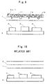
- the related art 3 of Fig.12 shows a general use of a paint 6 painted to a surface of the metal chassis 1 that can become high in temperature at the surface.
- the related art 4 discloses a technique to deal with the high temperature by using a paint with mixed micro-capsules that are thermally expandable.
- the thermally expandable micro-capsules are foamed by heating them.
- thermosetting paint contains 5 ⁇ 30 weight % of the thermally expandable micro-capsules in a paint having 70% of solid ingredient and painted to get the grain-like texture.
- the shell of the thermally expandable micro-capsules are softening at a temperature lower than a hardening temperature of a thermosetting resin.
- a coating step using thermosetting paint is done in a manner to get the grain-like texture, and this is dried by baking. During baking, the micro-capsules become ruptured from expansion. Accordingly, the film painted will harden to achieve the grain-like texture.
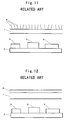
- Japanese unexamined patent application sho 62-39674 discloses a method of forming an insulating film with pattern. Paint compositions such as a pigment, a filler and a solvent are contained in a thermal plastic resinous vehicle. 10 ⁇ 80 weight % of the micro-capsules are contained in 100 weight % of the thermal plastic resinous vehicle. This paint is applied to surfaces of wall, ceiling and floor. Then the heating apparatus is used to heat the applied surfaces for drying to gain an expansion of the painted film. Accordingly, the insulating film with heated pattern is formed.
- a method of forming the film having a rough pattern is disclosed.
- the thermally expandable micro-capsules are dispersed in the paint.
- the paint become hardened at a temperature lower than a foaming temperature of the thermally expandable micro-capsules.
- the paint may be applied to all over or part of the surfaces, then hardened by heat. Then a final paint is applied on top of this layer, then hardened.
- the rough pattern is achieved by heating the micro-capsules over its foaming temperature.
- the coating method is reasonable in terms of productivity, design, and cost.
- the thickness of applied paint (film) is normally about 40 ⁇ m that the touching warmth from metallic substrate is not softened. The reduction of touching warmth cannot be expected from the normal coating method.
- the related art 4 describes a technique of forming the grain-like touch or the rough pattern that are formed by using the paint containing the thermally expandable micro-capsules and a technique of forming a pattern having a thermal insulating property. Neither of the techniques are aiming for a way to deal with the touching warmth, nor to soften the touching warmth from the metallic substrate.
- the present invention attempts to implement a method to deal with the touching warmth, by devising the surface processing method based on the coating method, maintaining advantages such as designs, surface applicability, productivity and low manufacturing cost.
- the present invention aims to soften the touching warmth at the surface of metallic mobile electronic devices, improve design/appearance of the product, and supply coating that is resistant to abrasions.
- the concepts of "insulating heat” and “softening the touching warmth” according to the present invention are two different concepts. What is meant by “insulating heat” is to isolate the heat and the heat is not transmitted. For example, consider a case when the heat is generated inside the mobile electronic device. In this regard, the meaning of “insulating heat” is to shut the heat being generated in the mobile electronic device and this will result in a damage of the device. On the other hand, the meaning of "softening the touching warmth” is to reduce the heat flow to hand. When the heat being generated from inside the device spreads to outside of the substrate surface, an amount of heat flow to hand has to be reduced.
- the technique of "softening the touching warmth” for the present invention must satisfy the following two contradicting requirements, namely: spreading the heat generated inside the mobile electronic device through the substrate surface; and removing an unpleasant sensation perceived by the human body from the spreading heat.
- the present invention aims to provide a coating technique to ease the heat influence on the human body as well as maintaining the heat spreading property.
- a surface coated substrate comprises a metallic substrate having a surface and a film including a layer for reducing a touching warmth, wherein the film is coated on the surface.
- the film comprises a foamed layer made of a paint material which includes a foaming material.
- the film is further comprising a top coating layer on top of the foamed layer, wherein the top coating layer is having a high degree of hardness than the foamed layer.
- the top coating layer is made of a bead-containing paint.
- the paint material is a paint or a resinous coating material.
- the metallic substrate is made of one of an aluminum, a magnesium and an aluminum alloy and a magnesium alloy.
- the foamed layer is 50 ⁇ 1000 ⁇ m thick.
- the metallic substrate is formed using a die-casting.
- the layer for reducing the touching warmth is used in concealing and filling a dent and a wrinkle formed during the die-casting of the metallic substrate.
- the layer for reducing the touching warmth includes an insulating filler material.
- the layer for reducing the touching warmth includes a granulated insulating material.
- the film has a rough surface.
- a method for reducing the touching warmth by coating a surface of the metallic substrate is comprising steps of: painting the surface of metallic substrate using the paint material including the foaming material; and forming the foamed layer by drying the paint material with heat for foaming the foaming material.
- the method is further comprising a step of forming the top coating layer, which has a high degree of hardness than the foamed layer, on top of the foamed layer.
- the step of forming the top coating layer includes a step of painting the top coating layer using the bead-containing paint.
- Improvement in the paint is desirable as the way to deal with the design/appearance, the productivity and the low manufacturing cost required for the electronic device chassis.
- Trial tests are done for the coating method, using trial guides 1 to 3 described below.
- T m an intermediate temperature at the point of contact
- a method of making the rough surface is examined as the trial guide 3, for reducing a contact area of a surface with a finger. By doing so, thermal resistance is increased at the film surface, therefore, it is expected that an amount of heat transmission to hand is reduced.
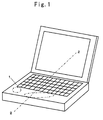
- Fig.1 illustrates an embodiment including the surface coated substrate prepared by the surface processing method of the present invention in dealing with the touching warmth.
- a part indicated by the elliptical outline in Fig.1 on the surface coated substrate is subjected to a high-temperature from a heating device 3 situated immediately below the outline.
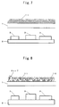
- Fig.2 is a side view of the surface coated substrate showing cross-section cut through A-A of Fig.1.
- metal chassis 1 for example, pure magnesium or a magnesium alloy is used. Or, pure aluminum or an aluminum alloy may also be used. Alternatively, other light metals with a density less than 4.0 g/cm 3 or 5.0g/cm 3 may be used.
- a resinous coating material 7 is applied first to form a base to increase a thickness of thermally insulating coating, so as to increase a thickness of the surface processed layers, and this will reduce the touching warmth at surface.
- vinyl chloride resin is suitable, where a thickness greater than 100 microns has proved to be effective as the base material.
- different types of paint materials (paint 6 and resinous coating material 7) are arranged to form a multi-layered films to increase the thickness of surface processed layers, thereby improving the touching warmth property.
- the following macromolecular compounds are examples that can be applied other than vinyl chloride resin: acrylic resin, fluorocarbon polymers, vinyl resin, phenol resin, polyester, epoxy resin, polyethylene, rubber, urea resin, meramine resin, polyurethane, silicone resin, and polyamide. These polymers can either be used alone or in combination.
- Fig.3 is the cross-section for a case of incorporating the thermally insulating layer, prepared by applying a paint made from mixing a fibrous insulating filler material 8 with the paint 6. The touching warmth is reduced by using the paint made from the mixing of insulating filler material 8 with the paint 6 because it lowers the thermal conductivity of the film layer.
- the insulating filler materials 8 are the materials with a low value of thermal conductivity and effective insulation, such as mica or pearlite.
- inorganic particles such as diatomaceous earth (SiO 2 +H 2 O), alumina powder (Al 2 O 3 +nH 2 O), calcium carbonate (CaCO 3 ), and titanium oxide (TiO 3 ) can be used.
- Fibrous materials of cattle leather and mixed leathers can also be used.
- the insulating filler material 8 also acts as a weight increaser, thereby increasing the thickness of film layer.
- the paint can also be made from mixing the insulating filler material 8 with the resinous coating material 7.
- Fig.4 is the cross-section of an embodiment of the surface coated substrate that incorporates a plurality of granulated insulating materials 9 in the film layer.
- the specific examples of the granulated insulating materials 9 are materials with a low value of thermal conductivity and effective insulation, such as cork powder or hollow beads to make gaseous entrapments, for example, air entrapments and hydrocarbon entrapments, inside the film.
- the thermal conductivity of the film layer will be effectively lowered to reduced the touching warmth.
- the granulated insulating materials can also become a weight increaser, therefore, it is able to increase the thickness of film layer.
- the granulated insulating material 9 can also be mixed with the resinous coating material 7.
- Other than the hollow beads following can be used: carbon balloon, acrylic and styrene, silicate mineral, silica-alumina fiber, and glass.
- the hollow beads and other materials such as carbon balloon can either be used alone or in combination.
- Fig.5 is the cross-section of a surface processed substrate that includes gaseous entrapments by pre-mixing a foaming material 10 with the paint, followed by foaming the mixed material at a high temperature.
- the thermally expandable micro-capsules such as hydrocarbons having a low boiling point are mixed in a normal paint.
- a porous structure is formed in the painted film, thereby reducing the thermal conductivity of the film layer and reducing the touching warmth.
- the foaming material can also increase the weight and thickness of the film layer.
- the foaming material 10 can also be mixed with the resinous coating material 7.
- foaming material 10 foaming glass, foaming concrete, foaming urethane, foaming styrene, foaming polypropylene, and foaming PET (polyethylene terephthalate) can either be used alone or in combination.
- the following materials may be included in the paint 6 or resinous coating material 7: alumina powder (Al 2 O 3 +nH 2 O), calcium carbonate (CaCO 3 ), and titanium oxide (TiO 3 ), silicate mineral, glass, acrylic and styrene beads. These materials will become a spacer to form gaseous entrapments. When painting the paint 6 and resinous coating material 7, the gaseous entrapments can be formed at the sides of the spacer.
- foaming material 10 monomers having a vapor pressure different from the paint 6 or the resinous coating material 7 can either be used alone or in combination. The gaseous entrapments are formed by volatization of the monomers at the time of painting.
- T 5 which controls the sensations perceived by people who have touched a particular high-temperature metallic surface
- Fig.6 An example that shows relationship between the thickness of the foamed film layer and touching warmth, T 5 , which controls the sensations perceived by people who have touched a particular high-temperature metallic surface, is shown in Fig.6.
- the touching warmth shows a prominent reduction, and, for the thickness of more than 300 ⁇ m or more than 1000 ⁇ m the touching warmth is constant regardless of film layer thickness.
- the thickness ranging from 50 to 1000 ⁇ m is found to be most effective.
- An effect of the present invention is calculated for evaluation using the heat transfer rate U as an index.
- the meaning of "softening the touching warmth” is to reduce the amount of heat flow from the mobile electronic device to hand and fingers in contact.
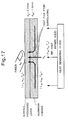
- a model illustration of Fig.17 shows a state of heat flow when human hand touches the metal chassis.
- the temperature will decreases at a portion of the aluminum chassis where the hand has touched, so a heat is supplied broadly from the surrounding in a horizontal direction.
- the thermal conductivity for the paint is lower than the thermal conductivity for the aluminum chassis by about 1/1000 of the thermal conductivity of the aluminum chassis. Therefore, the amount of heat supply of the paint from the horizontal direction is small.
- an effect of heat flow in a perpendicular direction shown in Fig.17 using thick arrows is considered to be dominant paths taken by the heat flowing to the hand.
- An evaluation for the amount of heat flow to the hand in one dimensional perpendicular direction is calculated using the heat transfer rate U as the index.
- U ⁇ p /d p
- the heat transfer rate (a parameter indicating a readiness of heat flow) in perpendicular direction of the surface processed substrate in the one dimensional model is calculated as below.
- the heat transfer rate for a case of normal coating process without using the foaming material 10 is calculated.
- the thermal conductivity ⁇ p1 for the paint used in the normal coating is considered to have the same thermal conductivity as epoxy and acrylic resins, which is 0.15(W/mK).
- the heat transfer rate will be 3750 (W /m 2 K) as shown in the equation of below.
- the combined thermal conductivity is assumed, by inversely calculating from a parallel heat resistance, to be 0.088 W/mK.
- the thickness of film d p2 is assumed to be 200 ⁇ m.
- the results are indicating the following effects.
- the combined thermal conductivity is decreased by a presence of numerous number of small gaseous entrapments that will be contained in the normal coating.
- thickness of film is increased by a presence of the foamed layer.
- the thermal conductivity of the layer for the case of using the foaming material is lower by about 1/10 of the normal coating.
- This effect of decreasing the amount of heat flow from the aluminum chassis to the hand appears as difference in characteristics for both cases of the normal coating and the coating using the foaming material.
- the heat transfer rate between the finger and the aluminum surface is the dominant heat transmitting parameter.
- the amount of heat flow to hand is eased by controlling the heat transfer rate by the foaming layer.
- Fig.7 shows an embodiment with repeatedly applied layers of bead-containing paint 11, increasing the layer thickness, and incorporated a porous structure with a large amount of gas incorporated in the film layers.
- This structure has the same effect as in embodiment 4.
- a bead-containing resinous coating material and multiple-layered glass are similarly used.
- Fig.8 is the example that combines embodiment 4 and embodiment 5.
- a decline in the restoring strength of the foaming material 10 is supplemented by the top coating with the bead-containing paint 11 because this can increase a hardness at the film surface.
- Foamed layer is prone to damage due to formations of porous structure and gas layers inside.
- Such surface of the foamed layer is top coated using a paint with high degree of hardness so that the strength of the film is intensified.
- a large difference between the conventional paint and the bead-containing paint is the way in which a pigment component is blended in the paint.
- the pigment is dispersed inside the conventional paint as it is.
- a large amount of "pigment enclosed using special resin to form minute bead-containing paint” or in other words, “pigmented beads” are contained in the bead-containing paint. These beads can give various colors to the paint.
- a scope of application is large for a well-balanced combination of the pigmented beads having varied radius. For instance, a suede-like film needs raised naps and knobby feels. In addition to a velvet or back skin and melange-like film that need a minor knobby feels, there is also a paint containing grounded natural collagen fibers with a flat painted surface.
- the hand contact area will be reduced by intentionally incorporating the rough surface, and reducing the thermal conductivity to the hand, so that excessive rise in touching warmth is prevented.
- Fig.9 shows an embodiment that appropriately combines the surface processing methods mentioned from embodiments 1 to 6, as well as aiming to fill a dent, wrinkle or scar at a surface formed during molding in die-casting.
- small dents or wrinkles 12 occur on its surface at an ejection stage, and repairs are generally made by puttying.
- a dent on the surface is a detriment that occurs during casting.
- a surface wrinkle is formed during casting when molten metal flows into a void casting frame.
- the method thick layer coating as shown in the embodiments 1 to 6 has a filling effect and conceals dents or wrinkles 12.
- there is no requirement to repairs with puttying thereby reducing costs, decreasing the number of processing steps, and improving quality.
- the metal chassis plate 1 becomes hot due to a heat generated from the heating device 3.
- the insulating layer structure is incorporated in the film layer.
- the mixing of insulating material is effective in reducing the amount of heat flow to a hand.
- mixing of the foaming material to form a foamed structure can create a rough structure at the surface of film which can reduce the touching warmth and effective in reducing the amount of heat flow to a hand.
- painting the paint or resinous coating material including the insulating material and gaseous entrapments can lower the thermal conductivity, so, the touching warmth reduction is improved significantly. Also, by intentionally forming a rough surface of a substrate, the contact area upon handling is reduced and effectively lowering the thermal conductivity to a hand. That is, the amount of heat flow to a hand is reduced by reducing the heat flow from the moment of handling the metal as well as afterward, reducing the touching warmth.
- the surface processing is done on various portions: throughout the external cover; to a part subjected to a change in temperature (e.g., the elliptical region of Fig.1); and to a part where there is a possibility of handling.
- a change in temperature e.g., the elliptical region of Fig.1
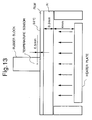
- the property of increasing temperature is measured by touching with a rubber block as dummy hand is shown in Fig.13.
- the temperature sensor is placed in a depth of 0.5mm inside the rubber hand.
- the sample A is the aluminum plate sized 105X150X0.3mm as a base with the normal epoxy coating.
- the sample B is the aluminum plate sized 105X150X0.3mm as the base with the foamed paint coating illustrated in Fig.8 of the present invention.
- the samples are heated using heaters located 4mm below, with a fixed surface temperature of 50°C.
- Touching warmth upon touching the samples are evaluated based on votes by 9 human testers.
- a sample C is further added for comparison besides samples A and B.
- the sample C is the ABS resinous plate with normal coating.
- the samples are heated using the same heating device as in the experimental study 1, and maintained the surface temperature of 46°C, in the room temperature of 25°C.
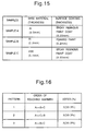
- the count up result of the response of testers touching the three samples are obtained, and is shown in Fig.16.
- the testers has reported the order and level of touching warmth of the samples.
- all testers has answered the sample A to be the hottest of all three samples (A>>B, A>>C).
- the touching warmth for the sample B was recognized to be substantially lower than the sample A, and the temperature of sample B was sensed to be close to the temperature of sample C.
- the processing for the present invention is easy and can be implemented on top of the existing conventional methods. For these reasons, the productivity increases and the cost is reduced.
- the rough surface when the rough surface is implemented, a smooth touch of coated surface which is characteristic of metallic surface is removed.
- the rough surface has a merit upon designing and appearance.
- the thick layer coating has the filling effect and conceals dents or wrinkles, thus there is no requirement to repair such detriments of small extent with putty, reducing costs, decreasing the number of production steps, and improving quality.
- porous film on the surface of chassis can increase the strengths against vibration and shock. Also, a noise prevention can be achieved from the effects of absorbing noise and sound insulation.
- the application of invention is not limited to a metal chassis, but can also be applied to other materials with high thermal conductivity.
Abstract
Description
- α1 :
- thermal diffusivity of human body (m2/S)
- β1 :
- thermal penetration rate of human body (W(√S)/(m2K))
- α2 :
- thermal diffusivity of touching object (m2/S)
- β2 :
- thermal penetration rate of touching object (W(√S)/(m2K))
- λ1 :
- thermal conductivity of human body (W/(mK))
- λ2 :
- thermal conductivity of touching object (W/(mK))
- T1 :
- temperature of human body (K)
- T2 :
- temperature of touching object (K)
- U:
- overall heat transfer rate in film (W/m2K)
- d:
- thickness of film (m)
- λp:
- thermal conductivity of film (W/(mK))
- λAl:
- thermal conductivity of aluminum (W/(mK))
- λa:
- thermal conductivity of air (W/(mK))
- αp:
- thermal diffusivity of film (m2/S)
- αAl:
- thermal diffusivity of aluminum (m2/S)
- αa:
- thermal diffusivity of air (m2/S)
- Tp:
- temperature of film (surface processed layer)(K)
- TAl:
- temperature of aluminum chassis (K)
- Ta:
- temperature of air (K)
- dp:
- thickness of film
- dAl:
- thickness of aluminum chassis
- qs:
- amount of heat flux
Claims (14)
- A surface coated substrate comprising:a metallic substrate having a surface; anda film including a layer for reducing a touching warmth, coated on the surface.
- The surface coated substrate according to claim 1, wherein the film includes a foamed layer made of a paint material including a foaming material.
- The surface coated substrate according to claim 2, wherein the film is further comprising a top coating layer on top of the foamed layer, wherein the top coating layer is having a high degree of hardness than the foamed layer.
- The surface coated substrate according-to claim 3, wherein the top coating layer is made of a bead-containing paint.
- The surface coated substrate according to claim 2, wherein the paint material is a paint or a resinous coating material.
- The surface coated substrate according to claim 1, wherein the metallic substrate is made of one of an aluminum, a magnesium, an aluminum alloy and a magnesium alloy.
- The surface coated substrate according to claim 2, wherein the foamed layer is 50∼1000 µm thick.
- The surface coated substrate according to claim 1, wherein the metallic substrate is formed using a die-casting, and wherein the layer for reducing the touching warmth is used in concealing and filling a dent and a wrinkle formed during the die-casting of the metallic substrate.
- The surface coated substrate according to claim 1, wherein the layer for reducing the touching warmth includes an insulating filler material.
- The surface coated substrate according to claim 1, wherein the layer for reducing the touching warmth includes a granulated insulating material.
- The surface coated substrate according to claim 1, wherein the film has a rough surface.
- A method for reducing the touching warmth by coating a surface of the metallic substrate comprising steps of:painting the surface of metallic substrate using the paint material including the foaming material; andforming the foamed layer by drying the paint material with heat for foaming the foaming material.
- The method according to claim 12 further comprising a step of forming the top coating layer, having a high degree of hardness than the foamed layer, on top of the foamed layer.
- The method according to claim 13, wherein the step of forming the top coating layer includes a step of painting the top coating layer using the bead-containing paint.
Applications Claiming Priority (6)
| Application Number | Priority Date | Filing Date | Title |
|---|---|---|---|
| JP126751/97 | 1997-05-16 | ||
| JP12675197 | 1997-05-16 | ||
| JP12675197 | 1997-05-16 | ||
| JP35660797A JP3106120B2 (en) | 1997-05-16 | 1997-12-25 | Portable electronic devices |
| JP356607/97 | 1997-12-25 | ||
| JP35660797 | 1997-12-25 |
Publications (3)
| Publication Number | Publication Date |
|---|---|
| EP0878989A2 true EP0878989A2 (en) | 1998-11-18 |
| EP0878989A3 EP0878989A3 (en) | 1999-08-25 |
| EP0878989B1 EP0878989B1 (en) | 2004-08-04 |
Family
ID=26462881
Family Applications (1)
| Application Number | Title | Priority Date | Filing Date |
|---|---|---|---|
| EP19980108464 Expired - Lifetime EP0878989B1 (en) | 1997-05-16 | 1998-05-08 | Surface coated substrate with reduced heat transmission |
Country Status (7)
| Country | Link |
|---|---|
| US (3) | US6303209B1 (en) |
| EP (1) | EP0878989B1 (en) |
| JP (1) | JP3106120B2 (en) |
| KR (1) | KR100266422B1 (en) |
| CN (1) | CN1195590C (en) |
| DE (1) | DE69825360T2 (en) |
| TW (1) | TW407457B (en) |
Cited By (1)
| Publication number | Priority date | Publication date | Assignee | Title |
|---|---|---|---|---|
| WO2013155470A1 (en) * | 2012-04-12 | 2013-10-17 | Qualcomm Incorporated | Heat dissipation features, electronic devices incorporating heat dissipation features, and methods of making heat dissipation features |
Families Citing this family (39)
| Publication number | Priority date | Publication date | Assignee | Title |
|---|---|---|---|---|
| TW553822B (en) * | 2000-11-22 | 2003-09-21 | Matsushita Electric Ind Co Ltd | Magnesium alloy moldings and method for manufacturing thereof |
| JP4599711B2 (en) * | 2000-12-27 | 2010-12-15 | 富士通株式会社 | Method of painting portable information device and portable information device using the same |
| US20030224198A1 (en) * | 2002-01-11 | 2003-12-04 | Nissan Technical Center North America, Inc. | Reusable masking device for sprayable bed liner |
| US7481267B2 (en) * | 2003-06-26 | 2009-01-27 | The Regents Of The University Of California | Anisotropic thermal and electrical applications of composites of ceramics and carbon nanotubes |
| US6976532B2 (en) * | 2003-06-26 | 2005-12-20 | The Regents Of The University Of California | Anisotropic thermal applications of composites of ceramics and carbon nanotubes |
| US7228894B2 (en) * | 2004-04-30 | 2007-06-12 | Hewlett-Packard Development Company, L.P. | Heat spreader with controlled Z-axis conductivity |
| DE102004058586A1 (en) * | 2004-12-03 | 2006-06-14 | Basf Ag | Halogen-free, flame-retardant, expandable styrene polymers |
| JP4556174B2 (en) * | 2004-12-15 | 2010-10-06 | 日本電気株式会社 | Portable terminal device and heat dissipation method |
| JP2007042863A (en) * | 2005-08-03 | 2007-02-15 | Matsushita Electric Ind Co Ltd | Electronic apparatus |
| US7355849B2 (en) * | 2006-01-09 | 2008-04-08 | Via Technologies, Inc. Of R.O.C. | Non-metal mesh cover for metal chassis |
| JP4730115B2 (en) * | 2006-01-30 | 2011-07-20 | パナソニック株式会社 | Memory card and manufacturing method thereof |
| JP4789670B2 (en) * | 2006-03-27 | 2011-10-12 | 富士通株式会社 | Resin molded product and manufacturing method thereof |
| JP4809095B2 (en) * | 2006-03-28 | 2011-11-02 | 富士通株式会社 | heatsink |
| US7440280B2 (en) * | 2006-03-31 | 2008-10-21 | Hong Kong Applied Science & Technology Research Institute Co., Ltd | Heat exchange enhancement |
| US20070230185A1 (en) * | 2006-03-31 | 2007-10-04 | Shuy Geoffrey W | Heat exchange enhancement |
| US7593229B2 (en) * | 2006-03-31 | 2009-09-22 | Hong Kong Applied Science & Technology Research Institute Co. Ltd | Heat exchange enhancement |
| US20080042109A1 (en) * | 2006-07-24 | 2008-02-21 | Walker Paul N | Mineral-enhanced computer component fabrication system and method |
| US20080149320A1 (en) * | 2006-10-19 | 2008-06-26 | Sony Ericsson Mobile Communications Ab | Electronic device with dual function outer surface |
| JP2009119672A (en) * | 2007-11-13 | 2009-06-04 | Fujitsu Ltd | Molded product of biodegradable resin and its manufacturing method |
| US7729108B2 (en) * | 2007-12-11 | 2010-06-01 | Dell Products, Lp | Information handling systems having coatings with porous particles and processes of forming the same |
| CN101573008B (en) * | 2008-04-28 | 2012-05-16 | 富准精密工业(深圳)有限公司 | Electronic device shell and manufacturing method thereof |
| MY155681A (en) * | 2009-08-04 | 2015-11-13 | Nippon Steel & Sumitomo Metal Corp | Pre-coated metal plate |
| US20110081839A1 (en) * | 2009-10-06 | 2011-04-07 | Apple Inc. | Method and apparatus for polishing a curved edge |
| US8892238B2 (en) * | 2009-10-06 | 2014-11-18 | Edward T. Sweet | Edge break details and processing |
| US20110089792A1 (en) * | 2009-10-16 | 2011-04-21 | Apple Inc. | Portable computer housing |
| TWI483093B (en) * | 2009-12-30 | 2015-05-01 | Foxconn Tech Co Ltd | Portable computer |
| CN103153017A (en) * | 2011-12-06 | 2013-06-12 | 神讯电脑(昆山)有限公司 | Manufacturing method for magnesium aluminum alloy housing |
| JP5496389B2 (en) * | 2012-06-06 | 2014-05-21 | セーレン株式会社 | Skin material |
| TWI576558B (en) * | 2012-09-14 | 2017-04-01 | 仁寶電腦工業股份有限公司 | Heat dissipation structure |
| US9606587B2 (en) * | 2012-10-26 | 2017-03-28 | Google Inc. | Insulator module having structure enclosing atomspheric pressure gas |
| GB2505538B (en) * | 2013-02-20 | 2014-07-23 | Amino Comm Ltd | Housing, apparatus and method |
| US11172126B2 (en) | 2013-03-15 | 2021-11-09 | Occipital, Inc. | Methods for reducing power consumption of a 3D image capture system |
| JP2014187230A (en) | 2013-03-25 | 2014-10-02 | Ricoh Co Ltd | Electronic apparatus and communication device |
| US9438775B2 (en) * | 2013-09-17 | 2016-09-06 | Occipital, Inc. | Apparatus for real-time 3D capture |
| US9430006B1 (en) | 2013-09-30 | 2016-08-30 | Google Inc. | Computing device with heat spreader |
| US8861191B1 (en) | 2013-09-30 | 2014-10-14 | Google Inc. | Apparatus related to a structure of a base portion of a computing device |
| US20150282381A1 (en) * | 2014-03-27 | 2015-10-01 | Compulab Ltd. | Heat sink device |
| US9442514B1 (en) | 2014-07-23 | 2016-09-13 | Google Inc. | Graphite layer between carbon layers |
| WO2016175779A1 (en) * | 2015-04-29 | 2016-11-03 | Hewlett-Packard Development Company, L.P. | Cover for devices |
Citations (8)
| Publication number | Priority date | Publication date | Assignee | Title |
|---|---|---|---|---|
| JPH02303573A (en) * | 1989-05-17 | 1990-12-17 | Sumitomo Metal Ind Ltd | Formation of coated film having rugged pattern |
| JPH04210012A (en) * | 1990-12-07 | 1992-07-31 | Matsushita Electric Ind Co Ltd | Electric heater |
| JPH067599A (en) * | 1992-06-26 | 1994-01-18 | Silver Kk | Iron |
| JPH0626659A (en) * | 1992-07-09 | 1994-02-04 | Matsushita Electric Ind Co Ltd | Grill door device |
| JPH0699133A (en) * | 1991-09-24 | 1994-04-12 | Fuji Toso Kk | Formation of film having woody feeling |
| JPH06296655A (en) * | 1993-04-16 | 1994-10-25 | Yoshihiko Azuma | Safety mechanism for surface type heating element to be used for sauna device |
| US5401348A (en) * | 1989-06-15 | 1995-03-28 | Dai Nippon Insatsu Kabushiki Kaisha | Soft coat film |
| JPH0874450A (en) * | 1994-09-02 | 1996-03-19 | Union:Kk | Door handle for building |
Family Cites Families (27)
| Publication number | Priority date | Publication date | Assignee | Title |
|---|---|---|---|---|
| JPS5110652Y1 (en) * | 1969-09-27 | 1976-03-23 | ||
| US3958313A (en) | 1974-06-05 | 1976-05-25 | Merchants National Bank Of Manchester | Method, apparatus and product for improved pipe-to-manhole sealing |
| JPS6019228Y2 (en) * | 1979-04-09 | 1985-06-10 | ロンシール工業株式会社 | roofing material |
| JPS5870865A (en) * | 1981-10-23 | 1983-04-27 | Ishikawajima Harima Heavy Ind Co Ltd | Method for coating reservoir for storing petroleum, coal or the like |
| JPS6019228A (en) | 1983-07-12 | 1985-01-31 | Toshiba Corp | Information input device |
| US4694119A (en) * | 1983-09-07 | 1987-09-15 | Sundstrand Data Control, Inc. | Heat shielded memory unit for an aircraft flight data recorder |
| JPS6239674A (en) | 1985-08-12 | 1987-02-20 | Shikoku Kaken Kogyo Co Ltd | Method of forming heat insulating pattern coating compound composition and heat insulating pattern film of coating |
| JPS63319085A (en) * | 1987-06-19 | 1988-12-27 | Nissan Motor Co Ltd | Coating method for chipping resistant paint film |
| JPS6411599A (en) | 1987-07-03 | 1989-01-17 | Fuji Car Mfg | Dry cleaning machine |
| JPS6411599U (en) * | 1987-07-08 | 1989-01-20 | ||
| US5258888A (en) * | 1991-03-15 | 1993-11-02 | Compaq Computer Corporation | Thermal packaging for natural convection cooled electronics |
| JP2957303B2 (en) * | 1991-04-18 | 1999-10-04 | 新日本製鐵株式会社 | Damping steel sheet with excellent workability and its manufacturing method |
| US5404271A (en) * | 1991-07-30 | 1995-04-04 | Kabushiki Kaisha Toshiba | Electronic apparatus having a card storing section formed within a body between a support frame and an upper case of the body and having functional elements mounted between the support frame and a lower case of the body |
| US5263773A (en) * | 1991-11-14 | 1993-11-23 | White Consolidated Industries, Inc. | Cabinet structure and method of producing same |
| JPH0732894A (en) | 1993-07-21 | 1995-02-03 | Hitachi Ltd | Fuel tank |
| JPH07256821A (en) * | 1994-03-22 | 1995-10-09 | Nisshin Steel Co Ltd | High hardness painted metal panel for lining turnnel |
| JP3676393B2 (en) * | 1994-06-02 | 2005-07-27 | マスプロ電工株式会社 | Electronic equipment housing |
| JP3487907B2 (en) * | 1994-06-30 | 2004-01-19 | 松下電器産業株式会社 | Cooker pot |
| JPH08290509A (en) * | 1995-04-20 | 1996-11-05 | Nippon Steel Corp | Warmth-sensitive coated steel pipe |
| JP3139939B2 (en) | 1995-05-30 | 2001-03-05 | 積水化学工業株式会社 | Laminated sheet for thermoforming and method for producing the same |
| JPH0957907A (en) * | 1995-08-25 | 1997-03-04 | Sekisui Chem Co Ltd | Laminated sheet |
| US5774333A (en) * | 1996-08-23 | 1998-06-30 | Speculative Incorporated | Thermally efficient portable computer incorporating deploying CPU module |
| US5991155A (en) * | 1996-12-13 | 1999-11-23 | Mitsubishi Denki Kabushiki Kaisha | Heat sink assembly including flexible heat spreader sheet |
| US6304459B1 (en) * | 1997-05-22 | 2001-10-16 | Xybernaut Corp. | Mobile computer |
| US5847925A (en) * | 1997-08-12 | 1998-12-08 | Compaq Computer Corporation | System and method for transferring heat between movable portions of a computer |
| US6055155A (en) * | 1998-02-18 | 2000-04-25 | International Business Machines Corporation | Case for portable computers for enhanced heat dissipation |
| US6073684A (en) * | 1998-02-23 | 2000-06-13 | Applied Thermal Technology | Clad casting for laptop computers and the like |
-
1997
- 1997-12-25 JP JP35660797A patent/JP3106120B2/en not_active Expired - Fee Related
-
1998
- 1998-04-16 US US09/061,089 patent/US6303209B1/en not_active Expired - Lifetime
- 1998-04-28 TW TW87106572A patent/TW407457B/en not_active IP Right Cessation
- 1998-05-08 KR KR1019980016397A patent/KR100266422B1/en not_active IP Right Cessation
- 1998-05-08 DE DE1998625360 patent/DE69825360T2/en not_active Expired - Lifetime
- 1998-05-08 EP EP19980108464 patent/EP0878989B1/en not_active Expired - Lifetime
- 1998-05-15 CN CNB981084648A patent/CN1195590C/en not_active Expired - Fee Related
-
2000
- 2000-05-30 US US09/580,451 patent/US6355332B1/en not_active Expired - Lifetime
- 2000-05-30 US US09/580,447 patent/US6358595B1/en not_active Expired - Lifetime
Patent Citations (8)
| Publication number | Priority date | Publication date | Assignee | Title |
|---|---|---|---|---|
| JPH02303573A (en) * | 1989-05-17 | 1990-12-17 | Sumitomo Metal Ind Ltd | Formation of coated film having rugged pattern |
| US5401348A (en) * | 1989-06-15 | 1995-03-28 | Dai Nippon Insatsu Kabushiki Kaisha | Soft coat film |
| JPH04210012A (en) * | 1990-12-07 | 1992-07-31 | Matsushita Electric Ind Co Ltd | Electric heater |
| JPH0699133A (en) * | 1991-09-24 | 1994-04-12 | Fuji Toso Kk | Formation of film having woody feeling |
| JPH067599A (en) * | 1992-06-26 | 1994-01-18 | Silver Kk | Iron |
| JPH0626659A (en) * | 1992-07-09 | 1994-02-04 | Matsushita Electric Ind Co Ltd | Grill door device |
| JPH06296655A (en) * | 1993-04-16 | 1994-10-25 | Yoshihiko Azuma | Safety mechanism for surface type heating element to be used for sauna device |
| JPH0874450A (en) * | 1994-09-02 | 1996-03-19 | Union:Kk | Door handle for building |
Non-Patent Citations (7)
| Title |
|---|
| PATENT ABSTRACTS OF JAPAN vol. 015, no. 080 (C-0810), 25 February 1991 & JP 02 303573 A (SUMITOMO METAL IND LTD), 17 December 1990 * |
| PATENT ABSTRACTS OF JAPAN vol. 016, no. 548 (C-1005), 18 November 1992 & JP 04 210012 A (MATSUSHITA ELECTRIC IND CO LTD), 31 July 1992 * |
| PATENT ABSTRACTS OF JAPAN vol. 018, no. 204 (C-1189), 11 April 1994 & JP 06 007599 A (SILVER KK), 18 January 1994 * |
| PATENT ABSTRACTS OF JAPAN vol. 018, no. 239 (M-1601), 9 May 1994 & JP 06 026659 A (MATSUSHITA ELECTRIC IND CO LTD), 4 February 1994 * |
| PATENT ABSTRACTS OF JAPAN vol. 018, no. 371 (C-1224), 13 July 1994 & JP 06 099133 A (FUJI TOSO KK), 12 April 1994 * |
| PATENT ABSTRACTS OF JAPAN vol. 095, no. 001, 28 February 1995 & JP 06 296655 A (YOSHIHIKO AZUMA), 25 October 1994 * |
| PATENT ABSTRACTS OF JAPAN vol. 096, no. 007, 31 July 1996 & JP 08 074450 A (UNION:KK), 19 March 1996 * |
Cited By (2)
| Publication number | Priority date | Publication date | Assignee | Title |
|---|---|---|---|---|
| WO2013155470A1 (en) * | 2012-04-12 | 2013-10-17 | Qualcomm Incorporated | Heat dissipation features, electronic devices incorporating heat dissipation features, and methods of making heat dissipation features |
| US9165854B2 (en) | 2012-04-12 | 2015-10-20 | Qualcomm Incorporated | Heat dissipation features, electronic devices incorporating heat dissipation features, and methods of making heat dissipation features |
Also Published As
| Publication number | Publication date |
|---|---|
| CN1201076A (en) | 1998-12-09 |
| EP0878989A3 (en) | 1999-08-25 |
| US6355332B1 (en) | 2002-03-12 |
| JP3106120B2 (en) | 2000-11-06 |
| US6303209B1 (en) | 2001-10-16 |
| CN1195590C (en) | 2005-04-06 |
| KR100266422B1 (en) | 2000-09-15 |
| DE69825360D1 (en) | 2004-09-09 |
| EP0878989B1 (en) | 2004-08-04 |
| DE69825360T2 (en) | 2005-08-04 |
| JPH1128419A (en) | 1999-02-02 |
| KR19980086851A (en) | 1998-12-05 |
| TW407457B (en) | 2000-10-01 |
| US6358595B1 (en) | 2002-03-19 |
Similar Documents
| Publication | Publication Date | Title |
|---|---|---|
| EP0878989B1 (en) | Surface coated substrate with reduced heat transmission | |
| US6097597A (en) | Thermo-siphon and manufacturing method of thermo-siphon and information processing apparatus | |
| US5354397A (en) | Sheet for covering a substrate and a method for producing a molding using the same | |
| JP2020128697A (en) | Elastic floor material product and its manufacturing method | |
| Harper et al. | Plastics materials and processes: a concise encyclopedia | |
| JP2004262105A (en) | Peach skin-like decorative sheet | |
| CA2380430A1 (en) | Laminate floor with footstep sound absorption | |
| JP3137938B2 (en) | Portable electronic devices | |
| JP2000148306A (en) | Electronic equipment case structure | |
| JPH0931371A (en) | Coating material composition and manufacture of coated board and decorative coated board | |
| JP2001057478A (en) | Portable electronic apparatus | |
| AU713135B2 (en) | Fire protection layers | |
| JP2002146087A (en) | Decorative material and method for producing the same | |
| US20090258136A1 (en) | Composite coating material and the production method of the same | |
| KR930019403A (en) | Decorative inlay floor or wall coatings and methods of making the same | |
| JP2008230037A (en) | Decorative sheet, decorative molded object using decorative sheet and manufacturing method of decorative molded object | |
| JP4170732B2 (en) | Manufacturing method of three-dimensional pattern printing plate | |
| JP4014293B2 (en) | Suede-like sheet material | |
| US20140147635A1 (en) | Composite coating material and the production method of the same | |
| JP3448449B2 (en) | Flooring and condominiums using it | |
| JPH06322934A (en) | Decorative laminate | |
| WO1997004938A1 (en) | Process for molding synthetic resins | |
| Makey et al. | Low Density Structural RIM: Glass Mat Reinforced Structural Foam for Interior Trim Applications | |
| TWI336270B (en) | ||
| JP2023132935A (en) | Decorative sheet and decorative material |
Legal Events
| Date | Code | Title | Description |
|---|---|---|---|
| PUAI | Public reference made under article 153(3) epc to a published international application that has entered the european phase |
Free format text: ORIGINAL CODE: 0009012 |
|
| AK | Designated contracting states |
Kind code of ref document: A2 Designated state(s): DE FI FR GB NL |
|
| AX | Request for extension of the european patent |
Free format text: AL;LT;LV;MK;RO;SI |
|
| PUAL | Search report despatched |
Free format text: ORIGINAL CODE: 0009013 |
|
| AK | Designated contracting states |
Kind code of ref document: A3 Designated state(s): AT BE CH CY DE DK ES FI FR GB GR IE IT LI LU MC NL PT SE |
|
| AX | Request for extension of the european patent |
Free format text: AL;LT;LV;MK;RO;SI |
|
| RIC1 | Information provided on ipc code assigned before grant |
Free format text: 6H 05K 5/02 A, 6B 05D 5/00 B, 6B 05D 7/14 B, 6C 23C 22/00 B |
|
| 17P | Request for examination filed |
Effective date: 20000223 |
|
| AKX | Designation fees paid |
Free format text: DE FI FR GB NL |
|
| 17Q | First examination report despatched |
Effective date: 20030306 |
|
| GRAP | Despatch of communication of intention to grant a patent |
Free format text: ORIGINAL CODE: EPIDOSNIGR1 |
|
| GRAS | Grant fee paid |
Free format text: ORIGINAL CODE: EPIDOSNIGR3 |
|
| GRAA | (expected) grant |
Free format text: ORIGINAL CODE: 0009210 |
|
| AK | Designated contracting states |
Kind code of ref document: B1 Designated state(s): DE FI FR GB NL |
|
| REG | Reference to a national code |
Ref country code: GB Ref legal event code: FG4D |
|
| REF | Corresponds to: |
Ref document number: 69825360 Country of ref document: DE Date of ref document: 20040909 Kind code of ref document: P |
|
| ET | Fr: translation filed | ||
| PLBE | No opposition filed within time limit |
Free format text: ORIGINAL CODE: 0009261 |
|
| STAA | Information on the status of an ep patent application or granted ep patent |
Free format text: STATUS: NO OPPOSITION FILED WITHIN TIME LIMIT |
|
| 26N | No opposition filed |
Effective date: 20050506 |
|
| REG | Reference to a national code |
Ref country code: GB Ref legal event code: 746 Effective date: 20110513 |
|
| REG | Reference to a national code |
Ref country code: DE Ref legal event code: R084 Ref document number: 69825360 Country of ref document: DE Effective date: 20110506 Ref country code: DE Ref legal event code: R084 Ref document number: 69825360 Country of ref document: DE Effective date: 20110704 |
|
| REG | Reference to a national code |
Ref country code: FR Ref legal event code: PLFP Year of fee payment: 19 |
|
| PGFP | Annual fee paid to national office [announced via postgrant information from national office to epo] |
Ref country code: GB Payment date: 20160504 Year of fee payment: 19 Ref country code: FI Payment date: 20160509 Year of fee payment: 19 Ref country code: DE Payment date: 20160504 Year of fee payment: 19 |
|
| PGFP | Annual fee paid to national office [announced via postgrant information from national office to epo] |
Ref country code: FR Payment date: 20160412 Year of fee payment: 19 |
|
| PGFP | Annual fee paid to national office [announced via postgrant information from national office to epo] |
Ref country code: NL Payment date: 20170412 Year of fee payment: 20 |
|
| REG | Reference to a national code |
Ref country code: DE Ref legal event code: R119 Ref document number: 69825360 Country of ref document: DE |
|
| GBPC | Gb: european patent ceased through non-payment of renewal fee |
Effective date: 20170508 |
|
| PG25 | Lapsed in a contracting state [announced via postgrant information from national office to epo] |
Ref country code: FI Free format text: LAPSE BECAUSE OF NON-PAYMENT OF DUE FEES Effective date: 20170508 |
|
| REG | Reference to a national code |
Ref country code: FR Ref legal event code: ST Effective date: 20180131 |
|
| PG25 | Lapsed in a contracting state [announced via postgrant information from national office to epo] |
Ref country code: GB Free format text: LAPSE BECAUSE OF NON-PAYMENT OF DUE FEES Effective date: 20170508 Ref country code: DE Free format text: LAPSE BECAUSE OF NON-PAYMENT OF DUE FEES Effective date: 20171201 |
|
| REG | Reference to a national code |
Ref country code: NL Ref legal event code: MK Effective date: 20180507 |
|
| PG25 | Lapsed in a contracting state [announced via postgrant information from national office to epo] |
Ref country code: FR Free format text: LAPSE BECAUSE OF NON-PAYMENT OF DUE FEES Effective date: 20170531 |