EP0878756A2 - Magnetplatte und Magnetplattensteuergerät - Google Patents
Magnetplatte und Magnetplattensteuergerät Download PDFInfo
- Publication number
- EP0878756A2 EP0878756A2 EP19980301091 EP98301091A EP0878756A2 EP 0878756 A2 EP0878756 A2 EP 0878756A2 EP 19980301091 EP19980301091 EP 19980301091 EP 98301091 A EP98301091 A EP 98301091A EP 0878756 A2 EP0878756 A2 EP 0878756A2
- Authority
- EP
- European Patent Office
- Prior art keywords
- magnetic disk
- format
- array
- magnetic
- divided
- Prior art date
- Legal status (The legal status is an assumption and is not a legal conclusion. Google has not performed a legal analysis and makes no representation as to the accuracy of the status listed.)
- Withdrawn
Links
Images







Classifications
-
- G—PHYSICS
- G06—COMPUTING OR CALCULATING; COUNTING
- G06F—ELECTRIC DIGITAL DATA PROCESSING
- G06F3/00—Input arrangements for transferring data to be processed into a form capable of being handled by the computer; Output arrangements for transferring data from processing unit to output unit, e.g. interface arrangements
- G06F3/06—Digital input from, or digital output to, record carriers, e.g. RAID, emulated record carriers or networked record carriers
- G06F3/0601—Interfaces specially adapted for storage systems
- G06F3/0602—Interfaces specially adapted for storage systems specifically adapted to achieve a particular effect
- G06F3/061—Improving I/O performance
-
- G—PHYSICS
- G06—COMPUTING OR CALCULATING; COUNTING
- G06F—ELECTRIC DIGITAL DATA PROCESSING
- G06F3/00—Input arrangements for transferring data to be processed into a form capable of being handled by the computer; Output arrangements for transferring data from processing unit to output unit, e.g. interface arrangements
- G06F3/06—Digital input from, or digital output to, record carriers, e.g. RAID, emulated record carriers or networked record carriers
- G06F3/0601—Interfaces specially adapted for storage systems
- G06F3/0628—Interfaces specially adapted for storage systems making use of a particular technique
- G06F3/0638—Organizing or formatting or addressing of data
-
- G—PHYSICS
- G06—COMPUTING OR CALCULATING; COUNTING
- G06F—ELECTRIC DIGITAL DATA PROCESSING
- G06F3/00—Input arrangements for transferring data to be processed into a form capable of being handled by the computer; Output arrangements for transferring data from processing unit to output unit, e.g. interface arrangements
- G06F3/06—Digital input from, or digital output to, record carriers, e.g. RAID, emulated record carriers or networked record carriers
- G06F3/0601—Interfaces specially adapted for storage systems
- G06F3/0668—Interfaces specially adapted for storage systems adopting a particular infrastructure
- G06F3/0671—In-line storage system
- G06F3/0673—Single storage device
- G06F3/0674—Disk device
- G06F3/0676—Magnetic disk device
Definitions
- the present invention relates to a peripheral device of an electronic computer system, and more specifically to a magnetic disk and a magnetic disk control apparatus capable of shortening the time taken in accessing a plurality of logical disks when a physical disk is divided into a plurality of logical disks.
- Magnetic disks are popularly used in peripheral devices of an electronic computer system.
- an FBA (fixed block architecture) disk used for a hard disk as a secondary storage device in a personal computer is divided into a plurality of logical disks for actual use.
- FIG. 1 shows an outline of the structure of a medium for a magnetic storage device.
- the magnetic storage device includes a plurality of media and a plurality of reading/writing heads.
- a medium has several hundreds through several thousands of tracks.
- a set of tracks at the same position from the bottom to the top is referred to as a cylinder.
- the entire device shown in FIG. 1 is a physical disk.
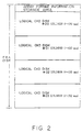
- FIG. 2 shows an example of a conventional method of arranging logical disks when a single logical disk, that is, an FBA disk, is divided into a plurality of logical disks.
- the FBA disk is divided into four logical disks (units #00 through #03).
- Each unit includes cylinders 0 through CKD max as groups of tracks viewed from a higher order device of the computer, that is the CPU.
- the CKD is an abbreviation for a count key data, and indicates that a CKD format in which a variable block size is used in the higher order device of the computer is adopted.
- a unit #00 is arranged outermost while a unit #03 is arranged innermost (at the center).
- the higher order device accesses a plurality of logical disks (units), there is a high probability that the first half of each logical disk is accessed. For example, when each logical disk shown in FIG. 2 has the cylinder numbers 0 through 1000, the higher order device probably accesses the cylinder numbers 0 through 100.
- the magnetic head moves for a long distance on the FBA disk, thereby taking a long time for a mechanical operation.
- the problem of the long movement of the head can be avoided if the next unit to be accessed exists on a different physical disk.
- the capacity of one physical disk is from several to 10 gigabytes while the capacity of one logical disk is 1.2 through 2.8 gigabytes. Therefore, when one logical disk unit is assigned to one physical disk, there is no problem of a long time required for movement, but there arises the problem of a high cost and a larger space required. Therefore, normally a plurality of logical units are assigned to a single physical disk. In such an environment, since a device accesses another unit on the same disk, the above described problem of a long time required for movement arises.
- the present invention aims at providing a magnetic disk and a magnetic disk control apparatus for shortening the time taken for a mechanical operation such as movement of a magnetic head during the operation of the magnetic disk so that the efficiency in accessing to a secondary storage device can be improved.
- the magnetic disk according to the present invention is used in a magnetic storage system including a magnetic disk control apparatus provided between a higher order device for issuing a data input/output instruction to a lower order magnetic storage device and a lower order magnetic storage device in a variable or fixed length storage format.
- a feature of the magnetic disk according to the present invention resides in that, when one or more physical disks are divided into a plurality of units as logical disks, one or more of the plurality of units are further divided into a plurality of appropriately arranged areas.
- the magnetic disk according to the present invention can include an area for storing array format information about the array format of the above described divided areas.
- the magnetic disk control apparatus is capable of reading the array format information so that it can recognize the array of the divided areas.
- the magnetic disk control apparatus can convert the storage format to adjust the difference.
- the time taken for a mechanical operation such as a seeking operation required when access is gained from one logical CKD disk to another logical CKD disk can be shortened, and the process time in accessing a plurality of units can also be shortened.
- the array on a disk can be recognized by containing in a physical disk array format information about the array of logical disks on a physical disk and by fetching the information on the control apparatus side. Therefore, even if there are disks having different array formats, the disks can be appropriately controlled, thereby largely improving the entire efficiency of an electronic computer system having a secondary storage device.
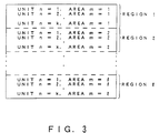
- FIG. 3 shows a system of arranging logical disks on a magnetic disk embodying the present invention. That is, FIG. 3 shows the system of arranging logical disks on a magnetic disk used in a magnetic storage system including a magnetic disk control apparatus provided between a higher order device for issuing a data input/output instruction to a lower order magnetic storage device and a lower order magnetic storage device in a variable or fixed length storage format. It further shows the state in which, when one or more physical disks are divided into a plurality of units as logical disks, one or more of the plurality of units are further divided into a plurality of appropriately arranged areas.
- the magnetic disk control apparatus can read the array format information to recognize the array of the divided areas.
- the magnetic disk control apparatus reads the array format information about each of one or more physical disks and stores the array format information in an area corresponding to each of the physical disks, thereby controlling each physical disk in a system containing physical disks having different array formats.
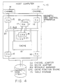
- FIG. 4 is a block diagram showing a configuration of the electronic computer system using the magnetic disk embodying the present invention.
- the system comprises a host computer 10 as a higher order device, a magnetic disk control apparatus 11, and a magnetic disk 12 as a lower order device.
- Two systems are provided for each of a channel adapter (CA) 15 as an interface module between a channel 14 of the host computer 10 and the magnetic disk control apparatus 11, and a device adapter (DA) 16 as an interface module between the magnetic disk control apparatus 11 and the magnetic disk 12.
- CA channel adapter
- DA device adapter
- the magnetic disk control apparatus 11 comprises a direct access storage device (DASD) subsystem, that is, a resource manager (RM) 17 as a module for controlling the allotment and release in the magnetic disk control apparatus 11 and the magnetic disk 12; a cache function engine (CFE) 18 as a module for managing the memory in the magnetic disk control apparatus, that is, a cache 19; table storage (TS) 20 and 21 for storing, for example, control information corresponding to the RM 17 and the CFE 18; and a C-bus 22 for communications among the modules such as the CA 15, DA 16, RM 17, CFE 18, and cache 19, etc.
- DASD direct access storage device
- RM resource manager
- CFE cache function engine
- TS table storage
- C-bus 22 for communications among the modules such as the CA 15, DA 16, RM 17, CFE 18, and cache 19, etc.
- a data input/output instruction is issued based on the variable length block size CKD (count key data) format at the host computer 10 as a higher order device.
- the magnetic disk 12 as a lower order device uses the fixed length block size FBA (fixed block architecture) format.
- the magnetic disk control apparatus 11 provided between the higher order device and the lower order device performs conversion between the CKD format and the FBA format as explained later.
- FIG. 5 shows an example of dividing the FBA disk according to the present embodiment.
- the FBS disk as a single physical disk is divided into four units #00 through #03 as four logical CKD disks.
- Each unit is further divided into n + 1 (cylinder number). That is, the array format information storage area indicating the array of the divided logical disks on the FBA disk is positioned on the outermost circumference of the disk.
- divided units 00 through 03 having the cylinder numbers 0 through n are arranged inside these divided areas.
- divided units 00 through 03 having the cylinder numbers n + 1 through 2n + 1 are arranged. All remaining divided areas are similarly arranged.
- the host computer 10 accesses the cylinder O/head O of the unit #03 after accessing the cylinder O/head O of the unit #00 of the magnetic disk 12, that is, the FBA disk shown in FIG. 5.
- the DA 16 in the magnetic disk control apparatus 11 computes the access position on the FBA disk from the value of the cylinder/head provided by the host computer 10 as described later, that is, computes the address, and issues a read command or a write command to the FBA disk. After transferring the data in the unit #00, a read/write command is issued to the unit #03.
- the magnetic head skips the units #01 and #02 on the FBA disk, and should be positioned for the unit #03.
- the time taken for a mechanical operation such as a seeking operation on the FBA disk can be shortened for the same cylinder number, and the disconnection time required at a unit switch can also be shortened.
- the array format information storage area at the start of the FBA disk shown in FIG. 5 stores array format information in such a way that the magnetic disk control apparatus 11 shown in FIG. 4 can recognize the array format of the logical disk on the FBA disk.
- the DA 16 in the magnetic disk control apparatus 11 can recognize whether the array format of the disk to be controlled is shown in FIG. 5 or FIG. 2 showing an example of the conventional system, by reading the data stored on the track for storing the array format information.
- the read result is stored in the memory not shown in FIG. 4 for each FBA disk of the lower order device so that the disks can be controlled even when the FBA disks in different array formats coexist.
- FIG. 6 is a flowchart showing the process, performed in the magnetic disk control apparatus 11 shown in FIG. 4, of reading array format information at the start of the FBA disk shown in FIG. 5.
- the reading process is performed as a part of the IML sequence in the magnetic disk control apparatus.
- the IML is short for initial microprogram loading.
- initial program loading IPL
- IML refers to restarting the apparatus.
- hardware initialization, and program loading are performed to a printed circuit board forming each module such as the CA 15, DA 16, etc. shown in FIG. 4 so that the magnetic disk control apparatus can be smoothly operated. Furthermore, a table provided in each of the CA, DA, etc. is reconstructed.
- step S1 when a part of the IML sequence is completed in step S1, the array format information of the FBA disk shown in FIG. 5 is read in steps S2 through S4.
- step S2 the array format information written at the start of the magnetic disk drive is read.
- step S3 the array format information is saved in the table of the magnetic disk control apparatus.
- step S4 it is determined whether or not all drive array format information has been read. If not, the processes in steps S2 through S4 are repeated. If yes, the process of the IML sequence continues in step S5.
- FIG. 7 shows an example of the storage in the array format information storage area shown in FIG. 5.
- the format ID in byte 0 indicates whether the array format of the logical disk is the conventional format shown in FIG. 2 or the format according to the present invention shown in FIG. 5.
- this area also stores the cylinder width, the number n of the cylinders in each of the divided areas shown in FIG. 5 can be variable.
- the DV type ID in byte 3 indicates the type of a device.
- FIG. 8 shows the record storage format in the CKD format.
- data is stored on the media for each of the count, key, data preceded by the home address (HA).
- the length of the key/data portions can be variable.
- a set of the count/key/data portions is referred to as a record.
- record 0 is formed by count ROC and data ROD, and contains no keys.
- the magnetic disk control apparatus 11 requires a converting process from the CKD format to the FBA format. Normally, this process is called a COF (CKD on FBA) control.
- 1-track data is divided into 4-kilobyte data blocks to process 1-track data in the CKD format shown in FIG. 8.
- This data block is the minimum unit in a staging process in the DA 16 described later.
- FIG. 9 shows the data block.
- the conversion into the data block is performed in the memory (cache 19) in the magnetic disk control apparatus 11.
- record RO contains count ROC and data ROD.
- the storage area for control information referred to as a data block ID is located at the start of one data block.
- the data block ID stores a cylinder value and a head value of a CKD disk, a record number of the data block, etc.
- the data block 0 has a special format, that is, contains only an HA (home address) and record 0 (R0). The area between the data block ID to the start of the HA is blank. The data of and after the record 1 (R1) in the record format of the CKD track is stored immediately after the ID of the data block 1.
- the data stored in a fixed-length data block in the magnetic disk control apparatus 11 is written to the FBA disk medium according to the format size of the FBA disk. Assuming that the format size of the FBA, that is, the length of the FBA block, is 1,024 bytes, the 4-kilobyte data of the data block shown in FIG. 9 is divided into four blocks and written to the FBA disk. FIG. 10 shows the result of dividing the data block 0 shown in FIG. 9. Similarly, the data block 1 and the subsequent blocks are divided into four blocks on the FBA disk.
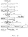
- FIG. 11 is a flowchart showing the staging process performed by the DA 16 as a process of reading data.
- the staging process is performed by storing the data to be read on the cache 19 when the magnetic disk control apparatus 11 receives an instruction to read data from the host computer 10.
- the DA 16 inquires of the CFE 18 whether or not the track data is stored in the cache 19. If the data is stored in the cache 19, the CA 15 transfers the data in the cache 19 to the host computer 10. If the data is not stored in the cache 19, then the DA 16 performs the staging process and the CA 15 transfers to the host computer 10 the data stored in the cache 19 by the DA 16.
- step S11 shown in FIG. 11 the DA 16 receives a start I/O instruction from the RM 17. As described above, the communications among the modules in the magnetic disk control apparatus 11 are established through the C-bus 22. The RM 17 issues to the DA 16 a C-bus command to perform the staging process. Based on the command number, the DA 16 recognizes that the staging process should be performed.
- step S12 shown in FIG. 11 the ATP/TCB is read from the TS 20 for the RM 17.
- the ATP active TCB pointer
- the ATP stores an address, etc. indicating where in the TS 20 the TCB (task control block) is stored.
- the ATP is read first.
- the TCB stores what process should be performed (which cylinder of which unit, which head record to be processed, read or write, etc.). Since a plurality of TCBs are stored in the TS 20, the ATP is read to determine the TCB to be read.
- step S13 it is inquired whether or not the track data, that is, the data of the track which contains the record to be read, is stored in the cache 19 for the CFE 18. It is determined in step S14 whether or not the data is stored in the cache. If yes, the data is transferred by the CA 15 to the host computer 10.
- step S15 the array format of the logical disk is checked in step S15 according to the array format information of the drive to be processed.
- step S16 it is determined whether or not the array of the logical disks is set for each logic.
- step S18 If it is set for each logic, that is, the array format of the conventional example shown in FIG. 2 is adopted, then the address of the leading block at which reading is to start is computed in step S18. If it is not set for each logic, that is, the array format according to the present invention shown in FIG. 5 is adopted, then the address of the leading block at which reading is to start is computed in step S17. The address computation is described later. Then, in step S19, a drive is selected, and a read command is issued.
- FIG. 12 shows each entry of the ATP.
- One entry of the ATP occupies 64 bytes.
- Entries for the maximum number of physical slots (the number of slots into which printed circuit boards used as each module are inserted) for each module such as the CA 15, DA 16, CFE 18, etc. shown in FIG. 4 exist in the RM/TS. For example, up to 16 printed circuit boards are used for the CA 15 and DA 16.
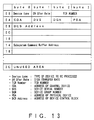
- FIG. 13 shows the structure of the data of the ATP for the DA 16.
- the data directly related to the present invention is the TCB number stored in bytes 2 and 3 of the first four bytes.
- the task control block (TCB) is stored in the RM/TS, and one entry occupies 256 bytes. Up to 1,024 TCBs can be generated in the RM/TS.
- FIG. 14 shows a storage area for one TCB. As shown in FIG. 14, one TCB entry comprises an RM exclusive area to be used by the RM for control, a common definition area, and a definition area for each type.
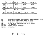
- FIG. 15 shows the contents of the common definition area.
- the TCB TYPE indicating the type of process
- the TASK CODE indicating the concrete process
- the structure of the definition area for each type shown in FIG. 14 is different for each TCB type. In the reading/writing process for a disk, a cylinder value, a head value, etc. for a disk are stored.
- the DA 16 receives a start operation instruction (start I/O instruction) from the RM 17 in step S11, the content of the process to be performed cannot be defined only based on the instruction itself. Therefore, it is necessary to read a TCB type/task code from the stored contents of the TCB. To know which of the 1,024 TCBs should be read, the ATP is first read. The ATP stores TCB numbers indicating which TCB should be read, and the DA 16 recognizes the contents of the process to be performed.
- start I/O instruction start I/O instruction
- CYL indicates a cylinder value specified by a higher order device.
- HD indicates a head value specified by a higher order device.
- OFFSET indicates an offset value of a logical disk in a physical disk. When one physical disk contains four logical disks as shown in FIGs. 2 and 5, the offset value is one of the values 0 through 3.
- the number of OFFSETs indicates the number of logical disks into which one physical disk is divided.
- CYL 2 indicates the number of cylinders contained in an area after dividing one logical disk into smaller areas. In FIG. 5, the number is n + 1.
- the number of FBA blocks per track is the number of FBA blocks for the capacity of one track of a CKD disk.
- the capacity of one track is a fixed value. For example, if the format size of an FBA block is 1,024 bytes, when the capacity of one track is 51 Kbytes, then one track corresponds to 52 FBA blocks.
- the cylinder value is basically regardless of the cylinder number shown in FIG. 5.
- the head value is regardless of the head number (head 0, ...) shown in FIG. 1.
- step S18 that is, in the case of the conventional example shown in FIG. 2, the address of the leading block at which reading is to start can be computed by the following equation. The meaning of the leading block is described later.
- the number of FBA blocks of the logical disks above the logical disk storing the track containing an object record is first computed by 1 above. Then, the number of tracks between the start of the logical disk containing the object record and the cylinder containing the object record is computed by 2 above. The computation result by 2 is added to the head value of 3 above to obtain the number of tracks before the track containing the object record. Then, the sum of 2 and 3 above is multiplied by the number of the FBA blocks per track to obtain the number of the FBA blocks between the start of the logical disk containing the object record and the object track. The product is added to the number of the FBA blocks obtained by 1 above to compute the number of the FBA blocks from the start of the FBA disk, that is, the address of the leading block at which reading is to start.
- step S17 Described below is the process in step S17, that is, the computation of the address of the leading block shown in FIG. 5.
- the address of the leading block is computed by the following equation.
- FIG. 16 is obtained by rearranging FIG. 5 into a horizontal format.
- the region containing cylinders 0 through n of unit #00 through #03 is region 0
- the region containing cylinders n + 1 through 2n + 1 is region 1, and so forth.
- the region containing the cylinder having the cylinder value specified by the higher order device is obtained from the quotient obtained by 1 above in the equation of the address computation, that is, the quotient as a value obtained by the division excluding the remainder.
- the number of cylinders contained in a region is obtained by 2 above.
- the number of cylinders (obtained by 3 above) before the start of the region containing the object record is obtained by multiplying 1 by 2, above.
- the number of cylinders between the start of the region and the start of the unit containing the object record is obtained by 4 above.
- the obtained value is added to 3 above to compute the number of cylinders between the start of the FBA disk and the start of the unit containing the object record.
- the result is added to 5 above obtained as a remainder of the division of 1 above, that is, the number of cylinders between the start of,the object unit and the object cylinder.
- the number of cylinders between the start of the FBA disk and the object cylinder of the object unit is computed.
- the number of tracks between the start of the FBA disk and the object cylinder of the object unit is obtained.
- the product is added to the head value specified by the higher order device to obtain the number of tracks between the start of the FBA disk and the object track in the object cylinder of the object unit.
- the address of the leading block containing the object record is computed by multiplying the number of tracks by the number of FBA blocks per track.
- the host computer 10 specifies a cylinder/head/record when accessing data on a disk. In some cases, the host computer 10 may additionally specify a sector value. If no sector values are specified, the data block 0 described by referring to FIG. 9 is a leading block to be handled in the staging process.
- the value obtained by adding 4 to the computed value described in step S17 is specified as an address to actually reading is to start.
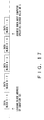
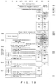
- FIG. 17 shows the result of the computation.
- the address to actually reading is to start is the address of the first of the four divided from the data block 1.
- a higher order device of an electronic computer system adopts the CKD format while the magnetic storage device as a lower order device adopts the FBA format.
- the magnetic disk and the magnetic disk control apparatus according to the present invention is not limited to such a combination.
- a higher order device may adopt the FBA format while a lower order device adopts the CKD format. Otherwise, a higher order device and a lower order device can adopt the same format.
- the present invention can be applicable to the case where the array of logical disks on a disk is based on the combination of the conventional system shown in FIG. 2 and the system according to the present invention.
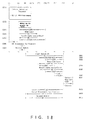
- FIGs. 18 through 20 show an operation flow of the process of reading records, which is instructed by a command from the host computer 10. In this process, it is determined which record should be processed according to a command transmitted and received between the channel (CH) 14 of the host computer 10 as a higher order device and the channel adapter (CA) 15 in the magnetic disk control apparatus 11.
- CH channel
- CA channel adapter
- the operation flow shows the processes performed among the channel (CH) 14 of the host computer 10; the channel adapter (CA) 15, the resource manager (RM) 17, the resource manager/table storage (RM/TS) 17/20, the cache function engine (CFE) 18, and the cache function engine/table storage (CFE/TS) 18/21 in the magnetic disk control apparatus 11; the extended storage port (ESP) for exchanging data when the CA, DA, RM, and CFE access a memory (read/write process); the SCSI device adapter (SDA); and the DV indicating a device/disk controlled by the DA 16.
- CA channel adapter
- RM resource manager
- RM/TS resource manager/table storage
- CFE cache function engine
- CFE/TS cache function engine/table storage
- the SCSI device adapter basically indicates the device adapter (DA) 16 in the magnetic disk control apparatus 11, and is called 'SDA' for short to distinguish it from a common DA, because in a certain type of a magnetic disk control apparatus an SCSI bus is used between the DA and the device.
Landscapes
- Engineering & Computer Science (AREA)
- Theoretical Computer Science (AREA)
- Human Computer Interaction (AREA)
- Physics & Mathematics (AREA)
- General Engineering & Computer Science (AREA)
- General Physics & Mathematics (AREA)
- Signal Processing For Digital Recording And Reproducing (AREA)
- Memory System Of A Hierarchy Structure (AREA)
Applications Claiming Priority (2)
| Application Number | Priority Date | Filing Date | Title |
|---|---|---|---|
| JP9121883A JPH10312646A (ja) | 1997-05-13 | 1997-05-13 | 磁気ディスクおよび磁気ディスク制御装置 |
| JP121883/97 | 1997-05-13 |
Publications (1)
| Publication Number | Publication Date |
|---|---|
| EP0878756A2 true EP0878756A2 (de) | 1998-11-18 |
Family
ID=14822287
Family Applications (1)
| Application Number | Title | Priority Date | Filing Date |
|---|---|---|---|
| EP19980301091 Withdrawn EP0878756A2 (de) | 1997-05-13 | 1998-02-13 | Magnetplatte und Magnetplattensteuergerät |
Country Status (2)
| Country | Link |
|---|---|
| EP (1) | EP0878756A2 (de) |
| JP (1) | JPH10312646A (de) |
Cited By (1)
| Publication number | Priority date | Publication date | Assignee | Title |
|---|---|---|---|---|
| US7133965B2 (en) * | 2003-12-15 | 2006-11-07 | Promise Technology, Inc. | Raid storage device |
Families Citing this family (1)
| Publication number | Priority date | Publication date | Assignee | Title |
|---|---|---|---|---|
| US6757797B1 (en) | 1999-09-30 | 2004-06-29 | Fujitsu Limited | Copying method between logical disks, disk-storage system and its storage medium |
-
1997
- 1997-05-13 JP JP9121883A patent/JPH10312646A/ja active Pending
-
1998
- 1998-02-13 EP EP19980301091 patent/EP0878756A2/de not_active Withdrawn
Cited By (1)
| Publication number | Priority date | Publication date | Assignee | Title |
|---|---|---|---|---|
| US7133965B2 (en) * | 2003-12-15 | 2006-11-07 | Promise Technology, Inc. | Raid storage device |
Also Published As
| Publication number | Publication date |
|---|---|
| JPH10312646A (ja) | 1998-11-24 |
Similar Documents
| Publication | Publication Date | Title |
|---|---|---|
| US5535372A (en) | Method and apparatus for efficient updating of CKD data stored on fixed block architecture devices | |
| US7464221B2 (en) | Storage system, storage device, and control method thereof | |
| US8028127B2 (en) | Automated on-line capacity expansion method for storage device | |
| US5721840A (en) | Information processing apparatus incorporating automatic SCSI ID generation | |
| US7069373B2 (en) | USB endpoint controller flexible memory management | |
| US5887128A (en) | Method and apparatus for redundant disk storage system with offset | |
| EP0806005A2 (de) | Verfahren und anordnung zum betrieb eines mit einem hauptrechner verbundenen massenspeicher-computerperipheriegerätes | |
| US7058692B2 (en) | Computer, computer system, and data transfer method | |
| EP0524809B1 (de) | Verfahren zur wahlweise Aufzeichnung oder Wiedergabe von Daten unter Verwendung eines Informationsverarbeitungssystems | |
| JP2000029635A (ja) | 記憶制御装置 | |
| US7054997B2 (en) | Disk array system and cache control method | |
| JP3242912B2 (ja) | 多段データ読取り装置 | |
| US6738879B2 (en) | Advanced technology attachment compatible disc drive write protection scheme | |
| JP4461089B2 (ja) | ストレージ制御装置およびストレージ制御方法 | |
| EP0669571B1 (de) | Verfahren und Gerät zur Aufzeichnung/Wiedergabe von Information | |
| US7941574B2 (en) | CKD partial record handling | |
| CN115391105B (zh) | 一种应用于存储设备的存储控制方法和装置 | |
| JPH10312646A (ja) | 磁気ディスクおよび磁気ディスク制御装置 | |
| US5860087A (en) | Data search method wherein the court-key-data (CKD) storage subsystem disconnects from the central processing unit when searching | |
| US20050262297A1 (en) | Disk drive connected to host system via memory interface circuit, and interface connecting method | |
| JP2001256001A (ja) | ディスクアレイ装置 | |
| JP2000222269A (ja) | リモートファイル制御装置 | |
| JP2005148910A (ja) | データ二重化装置及び方法 |
Legal Events
| Date | Code | Title | Description |
|---|---|---|---|
| PUAI | Public reference made under article 153(3) epc to a published international application that has entered the european phase |
Free format text: ORIGINAL CODE: 0009012 |
|
| AK | Designated contracting states |
Kind code of ref document: A2 Designated state(s): AT BE CH DE DK ES FI FR GB GR IE IT LI LU MC NL PT SE |
|
| AX | Request for extension of the european patent |
Free format text: AL;LT;LV;MK;RO;SI |
|
| STAA | Information on the status of an ep patent application or granted ep patent |
Free format text: STATUS: THE APPLICATION IS DEEMED TO BE WITHDRAWN |
|
| 18D | Application deemed to be withdrawn |
Effective date: 20010901 |